WO2010061791A1 - 映像制御装置およびそれを備えた撮像装置、表示装置 - Google Patents
映像制御装置およびそれを備えた撮像装置、表示装置 Download PDFInfo
- Publication number
- WO2010061791A1 WO2010061791A1 PCT/JP2009/069707 JP2009069707W WO2010061791A1 WO 2010061791 A1 WO2010061791 A1 WO 2010061791A1 JP 2009069707 W JP2009069707 W JP 2009069707W WO 2010061791 A1 WO2010061791 A1 WO 2010061791A1
- Authority
- WO
- WIPO (PCT)
- Prior art keywords
- sound
- motion vector
- image
- unit
- subject
- Prior art date
Links
- 230000033001 locomotion Effects 0.000 claims abstract description 230
- 239000013598 vector Substances 0.000 claims abstract description 191
- 238000012545 processing Methods 0.000 claims abstract description 37
- 238000001514 detection method Methods 0.000 claims abstract description 29
- 238000003384 imaging method Methods 0.000 claims description 66
- 230000005236 sound signal Effects 0.000 claims description 66
- 238000000034 method Methods 0.000 description 52
- 238000010586 diagram Methods 0.000 description 17
- 230000006870 function Effects 0.000 description 8
- 230000001965 increasing effect Effects 0.000 description 7
- 230000000694 effects Effects 0.000 description 5
- 238000013459 approach Methods 0.000 description 4
- 230000008569 process Effects 0.000 description 3
- 241000282412 Homo Species 0.000 description 2
- 230000001133 acceleration Effects 0.000 description 2
- 230000008901 benefit Effects 0.000 description 2
- 230000008859 change Effects 0.000 description 2
- 238000004891 communication Methods 0.000 description 2
- 238000011156 evaluation Methods 0.000 description 2
- XLYOFNOQVPJJNP-UHFFFAOYSA-N water Substances O XLYOFNOQVPJJNP-UHFFFAOYSA-N 0.000 description 2
- 208000036829 Device dislocation Diseases 0.000 description 1
- 241001465754 Metazoa Species 0.000 description 1
- 230000000295 complement effect Effects 0.000 description 1
- 238000011161 development Methods 0.000 description 1
- 230000018109 developmental process Effects 0.000 description 1
- 238000005516 engineering process Methods 0.000 description 1
- 230000002708 enhancing effect Effects 0.000 description 1
- 230000001771 impaired effect Effects 0.000 description 1
- 238000012986 modification Methods 0.000 description 1
- 230000004048 modification Effects 0.000 description 1
- ORQBXQOJMQIAOY-UHFFFAOYSA-N nobelium Chemical compound [No] ORQBXQOJMQIAOY-UHFFFAOYSA-N 0.000 description 1
- 230000003287 optical effect Effects 0.000 description 1
- 230000002093 peripheral effect Effects 0.000 description 1
- 230000011218 segmentation Effects 0.000 description 1
- 239000004065 semiconductor Substances 0.000 description 1
- 230000035807 sensation Effects 0.000 description 1
Images


Classifications
-
- H—ELECTRICITY
- H04—ELECTRIC COMMUNICATION TECHNIQUE
- H04N—PICTORIAL COMMUNICATION, e.g. TELEVISION
- H04N5/00—Details of television systems
- H04N5/14—Picture signal circuitry for video frequency region
- H04N5/144—Movement detection
- H04N5/145—Movement estimation
-
- H—ELECTRICITY
- H04—ELECTRIC COMMUNICATION TECHNIQUE
- H04N—PICTORIAL COMMUNICATION, e.g. TELEVISION
- H04N21/00—Selective content distribution, e.g. interactive television or video on demand [VOD]
- H04N21/40—Client devices specifically adapted for the reception of or interaction with content, e.g. set-top-box [STB]; Operations thereof
- H04N21/41—Structure of client; Structure of client peripherals
- H04N21/422—Input-only peripherals, i.e. input devices connected to specially adapted client devices, e.g. global positioning system [GPS]
- H04N21/4223—Cameras
-
- H—ELECTRICITY
- H04—ELECTRIC COMMUNICATION TECHNIQUE
- H04N—PICTORIAL COMMUNICATION, e.g. TELEVISION
- H04N21/00—Selective content distribution, e.g. interactive television or video on demand [VOD]
- H04N21/40—Client devices specifically adapted for the reception of or interaction with content, e.g. set-top-box [STB]; Operations thereof
- H04N21/43—Processing of content or additional data, e.g. demultiplexing additional data from a digital video stream; Elementary client operations, e.g. monitoring of home network or synchronising decoder's clock; Client middleware
- H04N21/439—Processing of audio elementary streams
-
- H—ELECTRICITY
- H04—ELECTRIC COMMUNICATION TECHNIQUE
- H04N—PICTORIAL COMMUNICATION, e.g. TELEVISION
- H04N21/00—Selective content distribution, e.g. interactive television or video on demand [VOD]
- H04N21/40—Client devices specifically adapted for the reception of or interaction with content, e.g. set-top-box [STB]; Operations thereof
- H04N21/43—Processing of content or additional data, e.g. demultiplexing additional data from a digital video stream; Elementary client operations, e.g. monitoring of home network or synchronising decoder's clock; Client middleware
- H04N21/44—Processing of video elementary streams, e.g. splicing a video clip retrieved from local storage with an incoming video stream or rendering scenes according to encoded video stream scene graphs
- H04N21/44008—Processing of video elementary streams, e.g. splicing a video clip retrieved from local storage with an incoming video stream or rendering scenes according to encoded video stream scene graphs involving operations for analysing video streams, e.g. detecting features or characteristics in the video stream
-
- H—ELECTRICITY
- H04—ELECTRIC COMMUNICATION TECHNIQUE
- H04N—PICTORIAL COMMUNICATION, e.g. TELEVISION
- H04N5/00—Details of television systems
- H04N5/76—Television signal recording
- H04N5/765—Interface circuits between an apparatus for recording and another apparatus
- H04N5/77—Interface circuits between an apparatus for recording and another apparatus between a recording apparatus and a television camera
- H04N5/772—Interface circuits between an apparatus for recording and another apparatus between a recording apparatus and a television camera the recording apparatus and the television camera being placed in the same enclosure
-
- H—ELECTRICITY
- H04—ELECTRIC COMMUNICATION TECHNIQUE
- H04S—STEREOPHONIC SYSTEMS
- H04S7/00—Indicating arrangements; Control arrangements, e.g. balance control
- H04S7/30—Control circuits for electronic adaptation of the sound field
-
- H—ELECTRICITY
- H04—ELECTRIC COMMUNICATION TECHNIQUE
- H04S—STEREOPHONIC SYSTEMS
- H04S1/00—Two-channel systems
- H04S1/007—Two-channel systems in which the audio signals are in digital form
-
- H—ELECTRICITY
- H04—ELECTRIC COMMUNICATION TECHNIQUE
- H04S—STEREOPHONIC SYSTEMS
- H04S2400/00—Details of stereophonic systems covered by H04S but not provided for in its groups
- H04S2400/11—Positioning of individual sound objects, e.g. moving airplane, within a sound field
-
- H—ELECTRICITY
- H04—ELECTRIC COMMUNICATION TECHNIQUE
- H04S—STEREOPHONIC SYSTEMS
- H04S2400/00—Details of stereophonic systems covered by H04S but not provided for in its groups
- H04S2400/13—Aspects of volume control, not necessarily automatic, in stereophonic sound systems
Definitions
- the present invention relates to a control technology for an imaging device and a display device, and more particularly to a method for controlling an image and sound.
- the digital camera has as its main components an image pickup unit that picks up an image, a sound pickup unit that picks up sound, and a storage unit that records images and sound.
- an image pickup unit that picks up an image
- a sound pickup unit that picks up sound
- a storage unit that records images and sound.
- the video with a sense of presence referred to here is a video with a sense that a viewer who sees the captured video is actually on the spot. For example, even if you watch a picture of a waterfall in the living room, you can tell it without damaging the sparkle of water splashing when you see the waterfall directly, or the force of the sound of water falling into the waterfall. It is.
- Patent Document 1 proposes a volume control device that controls the volume level and the left / right volume balance according to the zoom magnification of the camera and the angle of the camera with respect to the subject. For example, when a subject that is talking in a video conference system or the like is photographed with a large zoom, control is performed such that an image with a volume increased in accordance with the zoom magnification is acquired.
- JP-A-9-168139 JP-A-9-168139
- the object of the present invention is to acquire a video with a higher presence.
- a video control apparatus is associated with a subject, a motion vector detection unit that detects a motion vector from the motion of the subject in the video signal, a sound image processing unit that associates the motion vector with a sound emitted from the subject, and a subject
- a sound control unit that controls sound based on a motion vector.
- the video control apparatus is characterized in that the position of a subject is specified based on position information in a display area or position information of divided blocks.
- the video control apparatus is characterized in that the position and volume of the subject are calculated based on a volume balance of at least two or more sound collecting units.
- the video control apparatus is characterized in that the sound control unit changes at least one of a loudness and a sound frequency linearly or nonlinearly based on a motion vector.
- the video control apparatus includes a setting unit that changes the degree of non-linearity or the linear inclination by a user setting.
- An imaging apparatus includes a camera lens that collects light, an imaging element that captures an image collected by the camera lens, a sound collection unit that collects sound from a subject, and a memory that records a video signal.
- a motion vector detection unit that detects a motion of a subject as a motion vector from an image captured by an image sensor, and sound image processing that associates the sound collected by the sound collection unit with the motion vector
- a sound control unit that controls a sound associated with the subject based on a motion vector, and the sound and the image controlled by the sound control unit are recorded in a storage unit.
- An imaging apparatus includes a camera lens that collects light, an imaging element that captures an image collected by the camera lens, a sound collection unit that collects sound from a subject, and a memory that records a video signal.
- a motion vector detecting unit that detects a motion of a subject as a motion vector from an image captured by the image sensor, and a sound image processing unit that associates the sound collected by the sound collecting unit with the motion vector
- a sound control unit that controls the associated sound based on the motion vector, the motion vector and sound association information associated by the sound image processing unit, the sound collected by the sound collection unit, And an image are recorded in a storage unit.
- the imaging apparatus is characterized in that in the sound control unit, the control of the sound controlled according to the motion vector is the volume of the sound collected by the sound collection unit.
- the image pickup apparatus is characterized in that in the sound control unit, the control of the sound controlled according to the motion vector is the frequency of the sound collected by the sound collection unit.
- An imaging apparatus includes a sensor that detects a movement direction and a movement amount of the imaging apparatus, and detects a motion vector of the imaging apparatus detected from the movement direction and the movement amount from a motion vector detected from the image.
- the motion vector of the subject is detected by removing the motion vector.
- a display device is a display device that includes an image signal display unit that displays an input image and a sound signal playback unit that plays back an input sound, and moves a subject from the video signal.
- a motion vector detection unit that detects a vector; a sound image processing unit that associates a sound emitted from a subject with a motion vector; and a sound control unit that controls a sound associated with the motion vector; The sound displayed on the signal display unit and controlled by the sound control unit is reproduced by the sound signal reproduction unit.
- a display device is a display device including an image signal display unit that displays an input image and a sound signal reproduction unit that reproduces an input sound, and the input video signal is image information.
- a sound control unit that controls sound that is associated with the motion vector, and includes sound information, image motion vector information, and sound information associated with the motion vector. The sound that is displayed on the image signal display unit and controlled by the sound control unit is reproduced by the sound signal reproduction unit.
- the video control apparatus of the present invention it is possible to acquire a video with enhanced realism by associating the movement of the subject with the sound.
- the imaging apparatus including the video control apparatus of the present invention, it is possible to capture a realistic video by associating the movement of the subject with the sound and controlling the sound according to the movement of the subject.
- a realistic video can be displayed by controlling the sound according to the movement of the subject.
- subject in this specification refers to an object that is mainly desired to be photographed in a video or the like, and is distinguished from the background. For example, humans, animals, vehicles, and the like are applicable.
- FIG. 1A is a functional block diagram showing a configuration example of a digital video camera according to the first embodiment of the present invention.
- the digital video camera according to the first embodiment includes a video control device 107 (dotted line portion) in the preceding stage of the storage unit 103.
- the video control device 107 includes a motion vector detection unit 102, a sound image processing unit 105, and a sound control unit 106.
- the video signal includes an image signal and a sound signal.
- the operation of each functional unit in FIG. 1A will be described below.
- An image collected by the camera lens 100 is captured by the image sensor 101.
- the image pickup device 101 includes a CCD (Charged Coupled Device) image sensor, a CMOS (Complementary MetalMetaOxide Semiconductor) image sensor, and the like.
- the image sensor 101 is driven by a sensor controller (not shown).
- An image signal 108 received by the image sensor 101 is input to the motion vector detection unit 102 of the video control device 107.
- the motion vector detection unit 102 detects a motion vector of the input image signal 108 and outputs a motion vector signal 110 to the sound image processing unit 105.
- the motion vector is a vector representing the moving direction and moving amount of the subject on the screen per unit time.
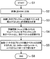
- a block matching method can be used to detect the motion vector. In the block matching method, inter-frame matching is performed in an appropriately determined block unit, and the most similar block between frames is determined as a corresponding block, and a motion vector is detected. The motion vector detection procedure by the block matching method will be described below based on the flowchart of FIG. 1B.
- step S1 the process is started (step S1). Assume that an image captured at time t is f 1 , and an image captured at time t + ⁇ is f 2 .
- the pixel value at the coordinates (x, y) in the image is represented by f (x, y).
- Processing procedure 1 The image f 1 is divided into N ⁇ M (N and M are arbitrary natural numbers, step S2).
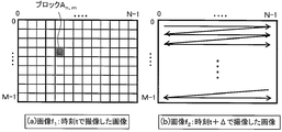
- FIG. 2 is a diagram illustrating a state of motion vector search.
- FIG. 2A shows an image f 2 captured at time t + ⁇ to detect the motion vector of the block An and m in the image f 1 captured at time t and the motion vector of the block An and m in FIG. It is a figure which shows the mode of search of.
- FIG. 2B the entire search is performed by the raster scan method, but the processing amount can be reduced by limiting the search range in the vicinity of the blocks An and m .
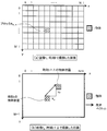
- FIG. 3 is a diagram illustrating an example of a motion vector search result.
- Image f 1 captured at time t in FIG. 3 (a) shows a diagram illustrating a motion vector detected with the image f 2 captured at time t + delta in FIG. 3 (b).
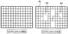
- the block size variable does not divide any image into a square lattice. For example, if there are humans and a background tree, the human is 1 block and the background tree is 1 block. This means that a block is assigned to what is shown in the image.
- the advantage of fixing the block size is that the processing is simple because it is only divided into square lattices, and there is a problem that the movement of the object is not taken into consideration.
- the advantage of making the block size variable is that it is possible to detect the rough movement of the object, and the problem is that the process needs to be divided according to the object in the image, so the processing is complicated It is to become.
- the block matching method is used for motion vector detection, but the same effect can be obtained even when the gradient method is used.
- the gradient method is a known technique for detecting a motion vector by calculating a constraint equation derived based on the assumption that a change in luminance in an image is caused only by the motion of an object.
- the sound collection unit 104 collects sound emitted from the subject.
- the sound collection unit 104 includes a stereo microphone and a microphone that can control directivity, and inputs the collected sound to the sound image processing unit 105 of the video control device 107.
- the sound image processing unit 105 associates the motion vector with the sound and outputs the sound 111 to the sound control unit 106.
- a method for associating the motion vector 110 with the sound 111 will be described below. Since the position of the moving subject is known from the motion vector detected by the motion vector detection unit 102, the sound collected at the position where the subject exists can be extracted and associated with the motion vector.
- the volume in the block can be calculated based on the balance between the left and right volume.
- the number of microphones for collecting sound is increased, the sound volume from a specific block or region can be obtained with high accuracy, particularly when four places are arranged in a plane.
- the volume in the left and right direction can be known, so that it is possible to grasp the simple volume at a certain position or region.
- the following method is applicable.
- Association method 1 This is a method in which a motion vector is detected for each divided block and a sound is associated with each block.
- Association method 2 An image is divided into regions based on color information and texture information, a motion vector is detected for each divided region, and a sound is associated with each region.
- Association method 3 Detecting a motion vector for each divided block, segmenting an image based on color information and texture information, and superimposing the motion vector detection result and the region segmentation result, This is a method of associating sounds with each region.
- the association method 1 is a method for associating motion vectors and sounds in units of blocks
- the association method 2 and the association method 3 are methods for associating motion vectors and sounds in units of regions.
- the associating method 1 is FIG. 4A fixed block size
- the associating methods 2 and 3 are FIG. 4B variable block size.
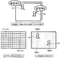
- FIG. 6 is a diagram showing a specific example of the association method. As shown in FIG. 6A, the captured moving image and the arrow indicate the motion vector, and the case of recording this will be described below.
- FIG. 6B is a diagram showing an example in which motion vectors and sounds are associated with each other in units of blocks. Block A and sound signal A are associated with each other, and block B and sound signal B are associated with each other.
- FIG. 6C shows an example of associating a motion vector with a sound in units of regions, in which region A and sound signal A are associated with each other, and region B and sound signal B are associated with each other.
- the correspondence information 112 between the sound signal and the motion vector processed by the sound image processing unit 105 is input to the sound control unit 106.
- the sound controller 106 controls the sound using the direction and magnitude of the motion vector.
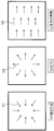
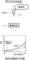
- the direction of the motion vector in the present embodiment, three types of (a) moving away direction, (b) approaching direction, and (c) horizontal movement shown in FIG. 7 will be described.
- the motion vector of the subject is in the direction of approaching (FIG. 7B)
- the associated sound is increased to give a sense of realism.
- a sense of reality is obtained by making the sound smaller.
- the sense of reality is enhanced by adjusting the left and right volume so that sound can be heard from the subject position.
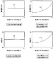
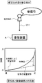
- FIGS. 8A and 8B show the difference between conventional sound control and sound control according to the present invention.
- the conventional sound control shown in FIG. 8A does not depend on the magnitude of the motion vector.
- the magnitude of the control amount of the sound is changed nonlinearly according to the magnitude of the motion vector to increase the force. Since a subject with a large motion vector has a high moving speed, the control amount of the sound is further increased to produce a flashy sound.
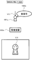
- FIG. 9 a case will be described in which a subject approaches while speaking out from the back of the drawing.
- the sound control amount is increased.
- FIG. 9B when the subject approaches the imaging device, the sound control amount is reduced.
- the sense of reality can be enhanced by changing the amount of sound control between when the subject walks and when the subject approaches and emphasizes the difference in motion of the subject (in this case, speed).
- the control amount is shown as an example of a positive value, but it may be a negative value.
- the control amount is set to a negative value, and the volume is reduced to increase the sense of reality.
- the sound control amount may be set to 0.
- FIG. 8 (c) and 8 (d) are diagrams showing the difference between the conventional sound frequency control and the sound frequency control according to this embodiment.
- the frequency is changed nonlinearly according to the magnitude of the motion vector, and it is associated with a subject having a large motion vector (fast moving speed).
- the sound corresponding to the movement of the subject is controlled by controlling the sound associated with the subject having a small motion vector (slow moving speed) to be a lower frequency.
- the frequency may be controlled according to the direction of the motion vector. For example, in the case of an image in which a car runs from left to right, the frequency of the engine sound associated with the car is changed. When the car approaches the imaging device from the left, increase the frequency. Conversely, when the car moves away from the imaging device to the right, it is possible to enhance the sense of reality by lowering the frequency.
- the loudness and the frequency of the sound are changed nonlinearly, but the sense of presence may be enhanced by changing linearly according to the degree of presence and the degree of desire to obtain force.
- the degree of nonlinearity may be adjusted.
- the degree of nonlinearity and the linear inclination may be changed by user settings. Further, even if only one of the volume and frequency of the sound is controlled, a sound signal with enhanced realism can be obtained.
- the storage unit 103 can record a video signal with enhanced realism by recording the image signal 109 and the sound signal 113.
- the example in which the image signal and the sound signal are recorded in the storage unit 103 has been described.
- the motion vector and the sound association information may be recorded.
- the difference between the information to be recorded (image signal and sound signal, motion vector and sound association information) will be described.
- the reproduction side Only sounds with amplified presence can be output.
- the motion vector and the sound association information are stored at the same time, it is possible to know where the object is present on the screen and how much the object has moved. Therefore, on the playback side, it is possible to make a sound from the position where the object is moving on the screen, or to amplify the sound to increase the sense of reality.
- the video control apparatus detects a motion vector from a video signal, associates the detected motion vector with a sound signal, and controls the sound based on the motion vector, thereby providing a sense of presence. It is possible to create a video signal with an improved image quality. Further, by providing the video control device in the imaging device, the captured video and the collected sound can be recorded in association with each other, and an imaging device capable of capturing a video with enhanced realism. Can be obtained.
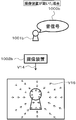
- FIG. 10 is a diagram illustrating motion vectors detected when the subject moves and when the imaging device moves.
- FIG. 10A is a diagram showing a motion vector when the imaging device 1002a is fixed and the subject 1001a moves.
- the motion vector appears on the moving subject 1001a and does not appear on the background without motion. Since the position of the moving subject 1001a is known from the motion vector appearance range, the sound signal 1000a emitted from the moving subject 1001a is collected and associated with the motion vector.
- FIG. 10B is a diagram illustrating a motion vector when the imaging device 1002b is moving and the subject 1001b is stationary.
- the motion vector appears in both the subject 1001b without motion and the background.
- a motion vector having substantially the same size appears in one of the three types of patterns shown in FIG. 7 in the entire image, it is estimated that the imaging device 1002b is moving.
- the sound signal 1000b is associated with the center of the screen.
- FIG. 7C it is estimated from the sound signal 1000b whether the sounding body is on the left or right, and the motion vector existing at the estimated position is associated with the sound signal.
- the sound signal picked up by the left microphone is compared with the sound signal picked up by the left microphone and the sound signal picked up by the right microphone. If the volume of is high, it is estimated that the subject is on the left side of the imaging apparatus.
- FIG. 11 is a diagram illustrating a motion vector when the imaging apparatus 1102 and the subject 1101 are moving together.
- the motion vector appears in both the moving subject 1101 and the background.
- the direction and magnitude of the motion vector appearing in the background may be different from those of the subject 1101 in motion, and the direction or magnitude of the motion vector may be different. is there.
- the subject 1101 is extracted from the difference between the direction and the magnitude of the motion vector.
- the extracted subject 1101 is associated with the sound signal.
- the motion of the imaging device is estimated from the motion vector, but an acceleration sensor or a gyro sensor can be used to estimate the motion of the imaging device.
- the motion vector of the imaging device is detected by an acceleration sensor or a gyro sensor, and is output to the motion vector detection unit 102.
- the motion vector detection unit 102 detects the motion vector of the subject by removing the motion vector of the imaging apparatus from the motion vector detected by the motion vector detection unit 102. Since the detected motion vector is a motion vector of a subject that is not affected by the motion of the imaging device, the same sound correlation method as in FIG. 10A can be used even if the imaging device is moving.
- a subject that is actually moving can be extracted by detecting the movement of the imaging apparatus with a sensor and combining the sensor detection value with the motion vector.
- a realistic video signal can be obtained.
- the motion vector is detected from the video signal, the detected motion vector and the sound signal are associated, and the motion vector is detected. It is possible to create a video signal with enhanced realism by controlling the sound by.
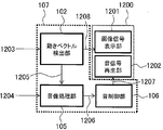
- FIG. 12 is a functional block diagram illustrating a configuration example of the display device according to the present embodiment. However, portions having the same functions as those in the first embodiment are denoted by the same reference numerals.
- a display device 1200 shown in FIG. 12 includes a video control device 107, an image signal display unit 1201, and a sound signal reproduction unit 1202.
- An input video signal includes an image signal and a sound signal.
- the image signal 1203 is input to the motion vector detection unit 102, and the sound signal 1204 is input to the sound image processing unit 105.
- the motion vector detection unit 102 detects the motion vector of the subject from the image signal 1203 using the method described in the first embodiment.
- the detected motion vector information 1205 is output to the sound image processing unit 105.
- the sound image processing unit 105 receives the sound signal 1204 and the motion vector information 1205, and associates the sound with the motion vector using the method described in the first embodiment.
- the sound image processing unit 105 outputs the sound signal, the motion vector, and the sound association information 1206 to the sound control unit 106.
- the sound control unit 106 controls the sound signal by using the method described in the first embodiment, and enhances the presence of the video.
- the sound control unit 106 outputs a sound signal 1207 with enhanced realism to the sound signal reproduction unit 1202.
- the image signal 1208 is output from the motion vector detection unit 102 to the image signal display unit 1201.
- the image signal 1208 is displayed on the image signal display unit 1201, and the sound signal 1207 is reproduced on the sound signal reproduction unit 1202, thereby reproducing an image with enhanced realism.
- the motion vector is detected from the image signal, the detected motion vector and the sound signal are associated, By controlling the sound with the vector, it is possible to display a video signal with enhanced realism.
- Example 4 a fourth embodiment of the present invention will be described in detail with reference to the drawings.
- the sound for collecting the sound collected by the imaging device, the motion vector detected by the video control device, and the sound association information are recorded in the storage unit, and the volume for enhancing the sense of presence using the motion vector on the display device Control is performed.
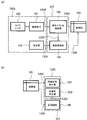
- 13 and 14 are functional block diagrams showing an example of the configuration of this embodiment. However, parts having the same functions as those in the first and third embodiments are denoted by the same reference numerals and description thereof is omitted.
- a video signal captured by an imaging device such as a web camera is stored in a storage unit such as a hard disk, and can be displayed on a display device such as a television or a monitor by reading the video signal from the storage unit. It is a thing.
- a video signal captured by an imaging device such as a digital camera is stored in a storage unit such as an optical disk or a memory card, and the video signal is read from the storage unit so that it can be displayed on a display device.
- the imaging device 1308 includes a camera lens 100, an imaging element 101, and a sound collection unit 104.
- An image signal 1300 obtained from the camera lens 100 and the image sensor 101 is output to the motion vector detection unit 102.
- the sound signal 1304 collected by the sound collection unit 104 is output to the sound image processing unit 105.
- the motion vector detection unit 103 detects a motion vector from the image signal 1300 using the method described in the first embodiment.
- the detected motion vector information 1303 is output to the sound image processing unit 105.
- the sound image processing unit 105 associates the motion vector information 1303 and the sound signal 1304 using the method described in the first embodiment.
- the image signal 1301 is input from the motion vector detection unit 102, and the sound signal, the motion vector, and the sound association information 1305 are input from the sound image processing unit 105 to the storage unit 103.
- the image information 1302 is output from the storage unit 103 to the image signal display unit 1201. Further, the sound signal, the motion vector, and the sound association information 1306 are output from the storage unit 103 to the sound control unit 106.
- the sound control unit 106 performs volume control using the method described in the first embodiment. From the sound control unit 106, the sound signal 1307 with enhanced realism is output to the sound signal reproduction unit 1202. In the display device 1200, the image signal 1302 is displayed on the image signal display unit 1201 and the sound signal 1307 is reproduced on the sound signal reproduction unit 1202.
- the storage unit 103 records sound signals, motion vectors, and sound association information. By doing so, it is possible to freely adjust the presence of the video on the display side.
- the motion vector is detected from the video signal obtained by the imaging device, and the detected motion vector and sound are detected.
- the signals By associating the signals with each other and controlling the sound using the motion vector, it is possible to display a video signal with enhanced realism.
- the video, the motion vector, and the sound association information recorded by the imaging device are recorded by the storage device. It is possible to change the realistic sensation of the video image with the display device.
- a program for realizing the functions described in the present embodiment is recorded on a computer-readable recording medium, and the program recorded on the recording medium is read into a computer system and executed to execute processing of each unit. May be performed.
- the “computer system” here includes an OS and hardware such as peripheral devices.
- the “computer system” includes a homepage providing environment (or display environment) if a WWW system is used.
- the “computer-readable recording medium” means a storage device such as a flexible disk, a magneto-optical disk, a portable medium such as a ROM and a CD-ROM, and a hard disk incorporated in a computer system. Furthermore, the “computer-readable recording medium” dynamically holds a program for a short time like a communication line when transmitting a program via a network such as the Internet or a communication line such as a telephone line. In this case, a volatile memory in a computer system serving as a server or a client in that case is also used to hold a program for a certain period of time.
- the program may be a program for realizing a part of the above-described functions, or may be a program that can realize the above-described functions in combination with a program already recorded in a computer system. .
- the present invention can be used for a digital video camera or the like.
Landscapes
- Engineering & Computer Science (AREA)
- Signal Processing (AREA)
- Multimedia (AREA)
- Physics & Mathematics (AREA)
- Acoustics & Sound (AREA)
- Studio Devices (AREA)
Abstract
映像信号における被写体の動きから動きベクトルを検出する動きベクトル検出部102と、動きベクトルと被写体から発せられた音とを対応付ける音像処理部105と、被写体と対応付けられた音を動きベクトルに基づいて制御する音制御部106と、を備えることを特徴とする。これにより被写体の動きと音を対応付けることにより、臨場感を高めた映像を取得するための映像制御装置を提供することが可能になる。
Description
本発明は、撮像装置および表示装置の制御技術に関し、特に、画像と音との制御方法に関する。
デジタルカメラは、画像を撮像する撮像部と、音を収音する収音部と、画像と音とを記録する記憶部と、を主要構成要素としている。人間の目で見たままの色と、人間の耳で聞いたままの音とをそのまま取得するために、撮像部と収音部との性能向上がなされてきた。近年、デジタルカメラにより風景をそのまま撮影するのではなく、臨場感のある映像を取得する撮像装置および臨場感のある映像を再生する表示装置の開発が進められている。ここで言う臨場感のある映像とは、撮像した映像を見た視聴者が、あたかも実際にその場にいるような感覚を持つ映像のことである。例えば、滝を撮影した映像をリビングで視聴した場合でも、直接滝を見たときに体感した水しぶきのきらめきや、水が滝つぼに落ちる音の迫力を損なうことなく伝えることのできるような映像のことである。
臨場感のある映像を取得するために、画像に関しては被写体の実際の色よりも鮮やかに撮像するという制御方法が開発されており、画像をより鮮やかに見せるため彩度や明るさを増加させて再生するという制御方法も開発されている。
また、音の制御方法に関しては、例えば、下記特許文献1で開示されている方法がある。特許文献1では、カメラのズーム倍率や被写体に対するカメラの角度に応じて音量レベルや左右の音量バランスを制御する音量制御装置が提案されている。例えば、テレビ会議システムなどで話をしている被写体を、ズームで大きく撮った場合、ズーム倍率に合わせて音量を大きくした映像を取得するような制御である。
特開平9-168139号公報
しかしながら、ズーム倍率や、被写体に対するカメラの角度、などの撮像側の操作によって、音量レベルや左右の音量バランスを可変とするカメラでは、被写体の動きが考慮されないため、臨場感が損なわれるという問題がある。
また、表示画面内に複数の被写体が存在する場合に、全ての被写体の動きと音を考慮することが難しいため、臨場感を十分に伝えることができないという問題があった。
本発明は、臨場感をより高めた映像を取得することを目的とする。
本発明にかかる映像制御装置は、映像信号における被写体の動きから動きベクトルを検出する動きベクトル検出部と、動きベクトルと被写体から発せられた音とを対応付ける音像処理部と、被写体と対応付けられた音を動きベクトルに基づいて制御する音制御部と、を備えることを特徴とする。
本発明にかかる映像制御装置は、被写体の位置を、表示領域内における位置情報又は分割したブロックの位置情報に基づいて特定することを特徴とする。
本発明にかかる映像制御装置は、被写体の位置と音量とは、少なくとも2以上の集音部の音量バランスに基づいて算出されることを特徴とする。
本発明にかかる映像制御装置は、音制御部は、音の大きさと音の周波数とのうち少なくとも一方を動きベクトルに基づいて線形又は非線形に変化させることを特徴とする。
本発明にかかる映像制御装置は、非線形の度合い又は線形の傾きをユーザ設定により変更する設定部を有することを特徴とする。
本発明にかかる撮像装置は、光を集光するカメラレンズと、カメラレンズによって集光した像を撮像する撮像素子と、被写体からの音を収音する収音部と、映像信号を記録する記憶部と、を備えた撮像装置であって、撮像素子で撮像した画像から被写体の動きを動きベクトルとして検出する動きベクトル検出部と、収音部で収音した音と動きベクトルとを対応付ける音像処理部と、被写体と対応付けられた音を動きベクトルに基づいて制御する音制御部と、を備え、音制御部において制御された音と画像とを記憶部に記録することを特徴とする。
本発明にかかる撮像装置は、光を集光するカメラレンズと、カメラレンズによって集光した像を撮像する撮像素子と、被写体からの音を収音する収音部と、映像信号を記録する記憶部と、を備えた撮像装置であって、撮像素子で撮像した画像から被写体の動きを動きベクトルとして検出する動きベクトル検出部と、収音部で収音した音と動きベクトルを対応付ける音像処理部と、対応付けられた音を動きベクトルに基づいて制御する音制御部と、を備え、音像処理部により対応付けられた動きベクトルと音の対応付け情報と、収音部で収音した音と、画像と、を記憶部に記録することを特徴とする。
本発明にかかる撮像装置は、音制御部において、動きベクトルに応じて制御する音の制御が、収音部で収音した音の音量であることを特徴とする。
本発明にかかる撮像装置は、音制御部において、動きベクトルに応じて制御する音の制御が、収音部で収音した音の周波数であることを特徴とする。
本発明にかかる撮像装置は、前記撮像装置の移動方向と移動量とを検出するセンサを備え、前記移動方向と前記移動量から検出した撮像装置の動きベクトルを、前記画像から検出した動きベクトルから除くことにより被写体の動きベクトルを検出することを特徴とする。
本発明にかかる表示装置は、入力された画像を表示する画像信号表示部と、入力された音を再生する音信号再生部と、を備える表示装置であって、映像信号から被写体の動きを動きベクトルとして検出する動きベクトル検出部と、被写体が発した音と動きベクトルを対応付ける音像処理部と、動きベクトルにより対応付けられた音を制御する音制御部と、を備え、映像信号の画像を画像信号表示部において表示し、音制御部において制御された音を音信号再生部において再生することを特徴とする。
本発明にかかる表示装置は、入力された画像を表示する画像信号表示部と、入力された音を再生する音信号再生部と、を備える表示装置であって、入力される映像信号が画像情報と、音情報と、画像の動きベクトル情報と、動きベクトルに対応付けられた音情報とを備え、動きベクトルにより対応付けられた音を制御する音制御部と、を備え、映像信号の画像を画像信号表示部において表示し、音制御部にて制御された音を音信号再生部において再生することを特徴とする。
本明細書は本願の優先権の基礎である日本国特許出願2008-303494号の明細書および/または図面に記載される内容を包含する。
本発明の映像制御装置によれば、被写体の動きと音とを対応付けることにより、臨場感を高めた映像を取得することができる。
また、本発明の映像制御装置を備える撮像装置によれば、被写体の動きと音とを対応付けることにより、被写体の動きに応じて音を制御することで臨場感のある映像を撮像できる。
さらに、本発明の映像制御装置を備える表示装置によれば、被写体の動きに応じて音を制御することで、臨場感のある映像を表示することができる。
100 カメラレンズ
101 撮像素子
102 動きベクトル検出部
103 記憶部
104 収音部
105 音像処理部
106 音制御部
107 映像制御装置
108 画像信号
109 画像信号
110 動きベクトル情報
111 音信号
112 音信号と動きベクトルと音の対応付け情報
113 音信号
1000a 音信号
1000b 音信号
1001a 被写体
1001b 被写体
1002a 撮像装置
1002b 撮像装置
1100 音信号
1101 被写体
1102 撮像装置
1200 表示装置
1201 画像信号表示部
1202 音信号再生部
1203 画像信号
1204 音信号
1205 動きベクトル情報
1206 音信号と動きベクトルと音の対応付け情報
1207 音信号
1300 画像信号
1301 画像信号
1302 画像信号
1303 動きベクトル情報
1304 音信号
1305 音信号と動きベクトルと音の対応付け情報
1306 音信号と動きベクトルと音の対応付け情報
1307 音信号
1308 撮像装置
本明細書における被写体とは、映像などにおいて主として撮影対象としたい対象物であり、背景と区別するものである。例えば、人間や動物、乗り物などが該当する。
以下、本発明の実施の形態について図面を参照しながら説明する。尚、各添付図における構成例は、理解しやすいように誇張して記載したものであり、実際の間隔や大きさとは異なるものである。
(実施例1)
図1Aは、本発明の第1実施例によるデジタルビデオカメラの一構成例を示す機能ブロック図である。第1実施例によるデジタルビデオカメラは、記憶部103の前段に映像制御装置107(点線部)を備えている。この映像制御装置107は、動きベクトル検出部102と音像処理部105と音制御部106とを備える。映像信号は、画像信号と音信号とを備えている。
図1Aは、本発明の第1実施例によるデジタルビデオカメラの一構成例を示す機能ブロック図である。第1実施例によるデジタルビデオカメラは、記憶部103の前段に映像制御装置107(点線部)を備えている。この映像制御装置107は、動きベクトル検出部102と音像処理部105と音制御部106とを備える。映像信号は、画像信号と音信号とを備えている。
図1Aの各機能部の動作について以下に説明する。カメラレンズ100によって集光した像を撮像素子101で撮像する。撮像素子101は、CCD(Charged Coupled Device)イメージセンサやCMOS(Complementary Metal Oxide Semiconductor)イメージセンサなどで構成される。撮像素子101は図示しないセンサコントローラで駆動される。撮像素子101で受け取った画像信号108が映像制御装置107の動きベクトル検出部102に入力される。
動きベクトル検出部102では、入力された画像信号108の動きベクトルを検出し、動きベクトル信号110を音像処理部105に対して出力する。ここで、動きベクトルとは、単位時間当たりの被写体の画面上での移動方向および移動量を表すベクトルである。動きベクトルの検出には、例えば、ブロックマッチング法を用いることができる。ブロックマッチング法とは、適切に定めたブロック単位でフレーム間照合を行い、フレーム間で最も類似するブロックを対応するブロックとし、動きベクトルの検出を行う。ブロックマッチング法による動きベクトル検出手順を図1Bのフローチャート図に基づいて以下に説明する。
まず処理を開始する(ステップS1)。時刻tで撮像した画像をf1、時刻t+Δで撮像した画像をf2とする。画像中の座標(x、y)における画素値を、f(x、y)で表す。画像f1と画像f2間との対応するブロックを探索するために、以下に示す処理手順1から4までを毎フレームで行う。
1)処理手順1:画像f1をN×Mに分割する(N,Mは任意の自然数、ステップS2)。
2)処理手順2:f1中のブロックをAn、m(n=0、1、…、N-1、m=0、1、…、M-1)とすると、ブロックAn、mの動きベクトルを検出するために評価関数を計算する(ステップS3)。ここでvn、m=(vx ,vy )は動きベクトルを表す。また、L(p,q)は距離関数を表しており、|p-q |や(p-q)2が用いられる。
3)処理手順3:評価関数E(vn、m)が最小となるvn、m=(vx,vy)をブロックAn、mの動きベクトルとする(ステップS4)。
図2は、動きベクトル探索の様子を示す図である。図2(a)は、時刻tで撮像した画像f1中のブロックAn、mを、(b)にブロックAn、mの動きベクトルを検出するために時刻t+Δで撮像した画像f2での探索の様子を示す図である。図2(b)では、ラスタスキャン方式で全探索をしているが、ブロックAn、mの近傍に探索範囲を限定することにより処理量の削減が可能である。
図3は、動きベクトルの探索結果の例を示す図である。図3(a)に時刻tで撮像した画像f1が示され、図3(b)に時刻t+Δで撮像した画像f2と検出した動きベクトルを示す図である。
4)処理手順4:画像f1中の全ブロックの動きベクトルを探索するため、処理手順2から3をn=0からn=N-1、m=0からm=M-1までnとmとを各々1ずつ増やしながら繰り返す(ステップS5)。本実施例では、画像f 1中の全ブロックの動きベクトルを検出した例を示したが、前フレームの動きベクトル情報を用い、動きベクトル検出範囲を限定することで処理量を削減することが可能である。上記処理手順1から処理手順4までを毎フレーム行い、動きベクトルを検出する。
尚、処理手順1では、図4(a)に示すように画像をN×Mに分割した例について示したが、図4(b)に示すようにブロックのサイズを可変にしても同様の効果を得ることができる。ブロックのサイズを可変にするための方法として、色情報やテクスチャ特徴による領域分割を用いることができる。
尚、ブロックサイズを可変にするとは、どのような画像でも正方格子に区切るのではなく、例えば人間と背景の木があった場合に、人間を1ブロック、背景の木を1ブロックというように、画像に映っている物に対してブロックを割り当てることを意味する。ブロックサイズ固定にした場合の利点は、正方格子に区切るだけなので処理が簡単であることであり、物体の動きを考慮していないという問題点がある。一方、ブロックサイズを可変にする利点は、物体の大まかな動きを検出することが可能であること、問題点は、画像中の物体に合わせて、領域を分割する必要があるため処理が複雑になることである。
本実施例では、動きベクトル検出に、ブロックマッチング法を用いたが、こう配法を用いても同様の効果を得ることができる。尚、こう配法とは、画像内の輝度変化は物体の動きのみにより生じるとの仮定に基づいて導かれた拘束方程式を計算することにより動きベクトルを検出する公知の手法である。
図1に戻り、収音部104では、被写体から発せられた音の収音を行う。収音部104は、ステレオマイクロフォンや指向性を制御できるマイクロフォンで構成され、収音した音を映像制御装置107の音像処理部105に入力する。
音像処理部105では、動きベクトルと音を対応付け、音制御部106に音111を出力する。動きベクトル110と音111との対応付け方法について以下に説明する。動きベクトル検出部102で検出した動きベクトルから、動いている被写体の位置がわかるため、被写体が存在する位置で収音した音を抽出し、動きベクトルと対応付けることができる。
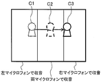
例えば、図5に示すように、被写体が図の左から右に移動すると仮定した場合、被写体が左にいるときは左マイクロフォンで収音された音を対応付ける。被写体が画面中央にいるときは左右両方のマイクロフォンで収音した音を、被写体が右にいるときは右マイクロフォンで収音した音を対応付ける。このように、左右の音量のバランスに基づいて例えばブロック内の音量を算出することができる。集音マイク数を多くすると、特に平面的に4箇所等配置するとある特定のブロック又は領域からの音量を精度良く求めることができる。左右2箇所のマイクであっても、左右方向の音量はわかるため、ある位置又は領域での簡略的な音量等を把握することは可能である。動きベクトルと収音した音との対応付け方法として、以下に挙げる方法が適用可能である。
1)対応付け方法1: 分割したブロック毎に、動きベクトルを検出し、各ブロックに対して音を対応付ける方法である。
2)対応付け方法2: 色情報やテクスチャ情報を基に画像を領域分割し、分割された領域毎に動きベクトルを検出し、各領域に音を対応付ける方法である。
3)対応付け方法3: 分割したブロック毎に動きベクトルを検出するとともに、色情報やテクスチャ情報を基に画像を領域分割し、動きベクトルの検出結果と、領域分割の結果とを重ねることで、各領域に音を対応付ける方法である。
上記の対応付け方法1は、ブロック単位に動きベクトルと音とを対応付ける方法であり、上記対応付け方法2と対応付け方法3とは、領域単位に動きベクトルと音とを対応付ける方法である。図4に示すブロックサイズの例では、対応付け方法1は図4(a)ブロックサイズ固定、対応付け方法2と3とは図4(b)ブロックサイズ可変となる。
図6は、対応付け方法の具体例を示す図である。図6(a)のように、撮像した動画、矢印は動きベクトルを示すものであり、これを記録する場合について以下に説明する。
図6(b)は、ブロック単位で動きベクトルと音とを対応付けした例を示す図であり、ブロックAと音信号Aとを対応付け、ブロックBと音信号Bとを対応付けている。図6(c)は、領域単位で動きベクトルと音を対応付ける例であり、領域Aと音信号Aとを対応付け、領域Bと音信号Bとを対応付けしている。
本実施例では、収音部104として左右からの音に対応するステレオマイクロフォンを用いた例について説明したが、3チャンネル以上を備えたマイクロフォンを用いても同様のように構成することで同様の効果を得ることができる。
音像処理部105で処理された音信号と動きベクトルとの対応付け情報112を音制御部106に入力する。音制御部106では、動きベクトルの向きと大きさとを利用して音を制御する。
動きベクトルの向きとして、本実施例では、図7に示す(a)の遠ざかる方向、(b)の近づく方向、(c)の左右方向の移動の3種類について説明を行う。被写体の動きベクトルが近づく方向であるとき(図7(b))、臨場感を出すために対応付けられた音をより大きくする。一方、被写体の動きベクトルが遠ざかる方向であるとき(図7(a))、音をより小さくすることで臨場感を出す。被写体の動きベクトルが左右方向の移動であるとき、被写体の位置から音が聞こえるように左右の音量を調節して出力することで臨場感を高める。
動きベクトルの大きさを利用した音の制御としては、音の制御量と音の周波数とを変化させる。図8(a)、(b)に、従来の音の制御と、本発明による音の制御の相違を示す。図8(a)に示す従来の音の制御は、動きベクトルの大きさに依存しない。図8(b)に示す本実施例では、動きベクトルの大きさに応じて非線形に音の制御量の大きさを変化させ、迫力を増加させている。動きベクトルの大きな被写体は移動速度が速いので、音の制御量を一層大きくして派手に音の演出を行う。
例えば、図9を参照して、被写体が図面の奥から手前に向けて声を出しながら近づく場合について説明する。図9(a)に示すように、被写体が撮像装置に向けて走り寄ってくるときは、音の制御量を大きくする。また、図9(b)に示すように、被写体が撮像装置に歩み寄るときは、音の制御量を小さくする。被写体が歩み寄る場合と走り寄る場合とで音の制御量を変化させ、被写体の動きの違い(この場合には速度)を強調することにより臨場感を高めることができる。
図9(a)、(b)では、制御量が正の値の例として示したが、負の値の場合でもよい。例えば、被写体が遠ざかるときは、制御量を負の値にし、音量を小さくすることで臨場感を高める。ここで、動きベクトルが小さい場合は音の制御量を0にしてもよく、動きベクトルの大きさに応じて適切な量で音を制御することで、臨場感の創出という効果を得ることができる。
図8(c)、(d)は、それぞれ、従来の音の周波数制御と、本実施例による音の周波数制御との相違を示す図である。この例(図8(d))では、図8(c)の場合と異なり、動きベクトルの大きさに応じて非線形に周波数を変化させ、動きベクトルの大きな(移動速度の速い)被写体に対応付けられた音をより高い周波数となるよう制御し、動きベクトルの小さな(移動速度の遅い)被写体に対応付けられた音をより低い周波数となるよう制御することで、被写体の動きに対応した音の制御を行う。また、動きベクトルの方向によって周波数を制御しても良く、例えば、車が左から右へ駆け抜ける映像の場合、車に対応付けられているエンジン音の周波数を変化させる。車が左から撮像装置に近付いてくるときは周波数を高くする。逆に、車が撮像装置から右へ遠ざかるときは周波数を低くすることで臨場感を高めることが可能である。
本実施例では、音の大きさと音の周波数とを非線形に変化させたが、臨場感や迫力を得たい度合いに応じて、線形に変化させて臨場感を高めてもよい。非線形の度合いを調整するようにしても良い。非線形の度合いや線形の傾きをユーザ設定により変更できるようにしても良い。また、音の大きさと周波数とのいずれか一方だけを制御しても臨場感を高めた音信号を得ることができる。
図1に示す動きベクトル検出部102から出力した画像信号109と音制御部106から出力した音信号113とを記憶部103に出力する。記憶部103では、画像信号109と音信号113とを記録することで、臨場感を高めた映像信号を記録することができる。
本実施例では、画像信号と音信号とを記憶部103で記録した例について説明したが、画像信号と音信号に加えて、動きベクトルと音の対応付け情報とを記録してもよい。尚、記録する情報(画像信号と音信号、動きベクトルと音の対応付け情報)により、どのような違いが有るかについて説明すると、画像信号と音信号を保存した場合において、再生側では画像と臨場感が増幅された音のみを出力可能である。画像信号と音信号に加えて、動きベクトルと音の対応付け情報を同時に保存しておくと、物体が画面中のどこに存在して、どのくらい動いたかがわかる。従って、再生側では画面上で物体が動いている位置から音を出したり、より臨場感を増すために音を増幅したりすることが可能となる。
以上のように、本実施例による映像制御装置によれば、映像信号から動きベクトルを検出し、検出された動きベクトルと音信号とを関連付け、動きベクトルによって音の制御を行うことにより、臨場感を高めた映像信号を作成することが可能となる。さらに、映像制御装置を撮像装置に備えることにより、撮像された映像と、収音された音とを関連付けて記録することが可能となり、臨場感を高めた映像を撮像することが可能な撮像装置を得ることが可能となる。
(実施例2)
以下、本発明の第2実施例について図面を参照しながら詳細に説明する。第2実施例では、被写体あるいは撮像装置が動いた場合と、被写体と撮像装置との両方が動いた場合について説明する。図10は、被写体が動いた場合と、撮像装置が動いた場合と、に検出される動きベクトルを示す図である。
以下、本発明の第2実施例について図面を参照しながら詳細に説明する。第2実施例では、被写体あるいは撮像装置が動いた場合と、被写体と撮像装置との両方が動いた場合について説明する。図10は、被写体が動いた場合と、撮像装置が動いた場合と、に検出される動きベクトルを示す図である。
図10Aは、撮像装置1002aは固定、被写体1001aが動いた場合の動きベクトルを示す図である。動きベクトルは動きのある被写体1001aに現れ、動きのない背景には現れない。動きベクトルの出現範囲から、動きのある被写体1001aの位置がわかるため、動きのある被写体1001aが発した音信号1000aを収音し、動きベクトルと対応付ける。
図10Bは、撮像装置1002bが動き、被写体1001bが静止している場合の動きベクトルを示す図である。動きベクトルは、動きのない被写体1001bと背景両方に現れる。画像全体におおむね同じ大きさの動きベクトルが図7に示す3種類のパターンのいずれかで現れる場合、撮像装置1002bが動いていると推定する。撮像装置の動きが、図7(a)、(b)と推定された場合、画面中心に音信号1000bを対応付ける。一方、撮像装置の動きが図7(c)と推定された場合、音信号1000bから発音体が左右どちらにいるかを推定し、推定した位置に存在する動きベクトルと音信号とを対応付ける。例えば、ステレオマイクロフォンで収音された音信号の場合に、左マイクロフォンで収音された音信号と右マイクロフォンで収音された音信号の音量とを比較し、左マイクロフォンで収音された音信号の音量が大きければ被写体は撮像装置に向かって左側にいると推定する。
図11は、撮像装置1102と被写体1101とがともに動いている場合の動きベクトルを示す図である。動きベクトルは動きのある被写体1101と背景との両方に現れる。撮像装置1102と被写体1101とがともに動いている場合に、動きのある被写体1101と背景に現れる動きベクトルの向きと大きさが異なる場合があり、また、動きベクトルの向きか大きさが異なる場合がある。撮像装置1102と被写体1101とがともに動いている場合に、動きベクトルの向きと大きさとの違いから、被写体1101を抽出する。抽出した被写体1101と音信号とを対応付ける。
前述の例では、動きベクトルから撮像装置の動きを推定したが、撮像装置の動きを推定するために加速度センサやジャイロセンサを用いることができる。例えば、撮像装置の動きベクトルを加速度センサやジャイロセンサで検出し、動きベクトル検出部102に出力する。動きベクトル検出部102では、撮像装置の動きベクトルを、動きベクトル検出部102で検出した動きベクトルから除くことで、被写体の動きベクトルを検出する。検出した動きベクトルは撮像装置の動きの影響を受けない被写体の動きベクトルなので、撮像装置が動いていたとしても、図10Aと同じ音の対応付け方法を用いることができる。
したがって、撮像装置の動きをセンサによって検出し、センサ検出値と動きベクトルとを合わせることにより、実際に動いている被写体を抽出することができる。この結果を用いて、動きベクトルと音との対応付けをすることにより臨場感のある映像信号を得ることができる。
以上に説明したように、本実施例による映像制御装置によれば、撮像装置が動いた場合においても、映像信号から動きベクトルを検出し、検出された動きベクトルと音信号とを関連付け、動きベクトルによって音の制御を行うことにより、臨場感を高めた映像信号を作成することが可能となる。
(実施例3)
以下、本発明の第3実施例について図面を参照して詳細に説明する。第3実施例は、図12は、本実施の形態による表示装置の一構成例を示す機能ブロック図である。但し、実施例1と同様の機能を有する部分については同一の符号を付している。図12に示す表示装置1200は、映像制御装置107と、画像信号表示部1201と、音信号再生部1202と、を備える。
以下、本発明の第3実施例について図面を参照して詳細に説明する。第3実施例は、図12は、本実施の形態による表示装置の一構成例を示す機能ブロック図である。但し、実施例1と同様の機能を有する部分については同一の符号を付している。図12に示す表示装置1200は、映像制御装置107と、画像信号表示部1201と、音信号再生部1202と、を備える。
図12の各機能部の動作を説明する。入力となる映像信号は、画像信号と音信号とを備える。画像信号1203を動きベクトル検出部102に入力し、音信号1204を音像処理部105に入力する。動きベクトル検出部102では、第1実施例に記載の方法を用いて、画像信号1203から被写体の動きベクトルを検出する。検出した動きベクトル情報1205を音像処理部105に出力する。
音像処理部105では、音信号1204と動きベクトル情報1205とを受け取り、第1実施例に記載の方法を用いて、音と動きベクトルとを対応付ける。音像処理部105から、音信号と動きベクトルと音の対応付け情報1206とを音制御部106に出力する。音制御部106では、第1実施例に記載の方法を用いて、音信号を制御し、映像の臨場感と、を高める。
音制御部106において臨場感を高めた音信号1207を音信号再生部1202に出力する。また、動きベクトル検出部102から画像信号1208を画像信号表示部1201に出力する。表示装置1200では、画像信号1208を画像信号表示部1201で表示するとともに、音信号1207を音信号再生部1202で再生することにより、臨場感を高めた映像を再生する。
以上のように、本実施例に記載の表示装置によれば、放送映像などの映像信号であっても、画像信号から動きベクトルを検出し、検出された動きベクトルと音信号とを関連付け、動きベクトルによって音の制御を行うことにより、臨場感を高めた映像信号を表示することが可能となる。
(実施例4)
以下、本発明の第4実施例について図面を参照して詳細に説明する。本実施例では、撮像装置で収音した音と映像制御装置で検出した動きベクトルと音の対応付け情報とを記憶部に記録し、表示装置で動きベクトルを用いて臨場感を高めるための音量制御を行うことを特徴とする。図13、14は、本実施例の構成例を示す機能ブロック図である。ただし、第1実施例及び第3実施例と同様の機能を有する部分については同一の符号を付して説明を省略している。
以下、本発明の第4実施例について図面を参照して詳細に説明する。本実施例では、撮像装置で収音した音と映像制御装置で検出した動きベクトルと音の対応付け情報とを記憶部に記録し、表示装置で動きベクトルを用いて臨場感を高めるための音量制御を行うことを特徴とする。図13、14は、本実施例の構成例を示す機能ブロック図である。ただし、第1実施例及び第3実施例と同様の機能を有する部分については同一の符号を付して説明を省略している。
図13では、例えばwebカメラなどの撮像装置で撮像した映像信号をハードディスクなどの記憶部に保存し、その記憶部から映像信号を読み込むことでテレビやモニタなどの表示装置に表示することができるようにしたものである。図14では、デジタルカメラなどの撮像装置で撮像した映像信号を光ディスクやメモリーカードなどの記憶部に保存し、記憶部から映像信号を読み込むことで表示装置に表示することができるようにしている。
図13、14について各部の動作を以下に説明する。
撮像装置1308は、カメラレンズ100と撮像素子101と収音部104とを備えている。カメラレンズ100と撮像素子101とから得られた画像信号1300を動きベクトル検出部102に出力する。収音部104で収音した音信号1304を音像処理部105に出力する。
動きベクトル検出部103では、第1実施例に記載の方法を用いて、画像信号1300から動きベクトルを検出する。検出した動きベクトル情報1303を音像処理部105に出力する。
音像処理部105では、第1実施例に記載の方法を用いて、動きベクトル情報1303と音信号1304とを対応付ける。動きベクトル検出部102から画像信号1301を、音像処理部105から音信号と動きベクトルと音の対応付け情報1305とを記憶部103に入力する。
記憶部103から画像情報1302を画像信号表示部1201に出力する。また、記憶部103から音信号と動きベクトルと音の対応付け情報1306を音制御部106に出力する。音制御部106では、第1実施例に記載の方法を用いて音量制御を行う。音制御部106から、臨場感を高めた音信号1307を音信号再生部1202に出力する。表示装置1200では、画像信号1302を画像信号表示部1201で表示し、音信号1307を音信号再生部1202で再生することにより、臨場感を高めた映像を表示することができる。
本実施例のように、表示側が動きベクトルと音の対応付け情報とを用いた音制御方法に対応していれば、記憶部103において、音信号と動きベクトルと音の対応付け情報とを記録することにより、表示側で映像の臨場感を自由に調節することが可能となる。
以上に説明したように、本実施例に記載の映像制御装置を備えた撮像装置及び表示装置によれば、撮像装置によって得られた映像信号から動きベクトルを検出し、検出された動きベクトルと音信号とを関連付け、動きベクトルによって音の制御を行うことにより、臨場感を高めた映像信号を表示することが可能となる。
本実施例に記載の映像制御装置を備えた撮像装置と表示装置とによれば、撮像装置で撮像した映像と動きベクトルと音の対応付け情報とを記憶装置で記録するため、撮像装置で撮像した映像の臨場感を表示装置にて変化させることが可能となる。
上記の実施の形態において、添付図面に図示されている構成等については、これらに限定されるものではなく、本発明の効果を発揮する範囲内で適宜変更することが可能である。その他、本発明の目的の範囲を逸脱しない限りにおいて適宜変更して実施することが可能である。
また、本実施の形態で説明した機能を実現するためのプログラムをコンピュータ読み取り可能な記録媒体に記録して、この記録媒体に記録されたプログラムをコンピュータシステムに読み込ませ、実行することにより各部の処理を行ってもよい。尚、ここでいう「コンピュータシステム」とは、OSや周辺機器等のハードウェアを含むものとする。
また、「コンピュータシステム」は、WWWシステムを利用している場合であれば、ホームページ提供環境(あるいは表示環境)も含むものとする。
また、「コンピュータ読み取り可能な記録媒体」とは、フレキシブルディスク、光磁気ディスク、ROM、CD-ROM等の可搬媒体、コンピュータシステムに内蔵されるハードディスク等の記憶装置のことをいう。さらに「コンピュータ読み取り可能な記録媒体」とは、インターネット等のネットワークや電話回線等の通信回線を介してプログラムを送信する場合の通信線のように、短時間の間、動的にプログラムを保持するもの、その場合のサーバやクライアントとなるコンピュータシステム内部の揮発性メモリのように、一定時間プログラムを保持しているものも含むものとする。また前記プログラムは、前述した機能の一部を実現するためのものであっても良く、さらに前述した機能をコンピュータシステムにすでに記録されているプログラムとの組み合わせで実現できるものであっても良い。
本発明は、デジタルビデオカメラなどに利用可能である。
Claims (12)
- 映像信号における被写体の動きから動きベクトルを検出する動きベクトル検出部と、
前記動きベクトルと被写体から発せられた音とを対応付ける音像処理部と、
前記被写体と対応付けられた音を前記動きベクトルに基づいて制御する音制御部と、
を備えることを特徴とする映像制御装置。 - 前記被写体の位置を、表示領域内における位置情報又は分割したブロックの位置情報に基づいて特定することを特徴とする請求項1に記載の映像制御装置。
- 前記被写体の位置と音量とは、少なくとも2以上の集音部の音量バランスに基づいて算出されることを特徴とする請求項1又は2に記載の映像制御装置。
- 前記音制御部は、音の大きさと音の周波数とのうち少なくとも一方を前記動きベクトルに基づいて線形又は非線形に変化させることを特徴とする請求項1から3までのいずれか1項に記載の映像制御装置。
- 前記非線形の度合い又は線形の傾きをユーザ設定により変更する設定部を有することを特徴とする請求項4に記載の映像制御装置。
- 光を集光するカメラレンズと、前記カメラレンズによって集光した像を撮像する撮像素子と、被写体からの音を収音する収音部と、映像信号を記録する記憶部と、を備えた撮像装置であって、
前記撮像素子で撮像した画像から被写体の動きを動きベクトルとして検出する動きベクトル検出部と、
前記収音部で収音した音と前記動きベクトルとを対応付ける音像処理部と、
前記被写体と対応付けられた音を前記動きベクトルに基づいて制御する音制御部と、を備え、
前記音制御部において制御された音と前記画像とを前記記憶部に記録することを特徴とする撮像装置。 - 光を集光するカメラレンズと、前記カメラレンズによって集光した像を撮像する撮像素子と、被写体からの音を収音する収音部と、映像信号を記録する記憶部と、を備えた撮像装置であって、
前記撮像素子で撮像した画像から被写体の動きを動きベクトルとして検出する動きベクトル検出部と、
前記収音部で収音した音と前記動きベクトルを対応付ける音像処理部と、
前記被写体と対応付けられた音を前記動きベクトルに基づいて制御する音制御部と、を備え、
前記音像処理部により対応付けられた動きベクトルと音の対応付け情報と、前記収音部で収音した音と、前記画像と、を前記記憶部に記録することを特徴とする撮像装置。 - 前記音制御部において、前記動きベクトルに応じて制御する音の制御が、前記収音部で収音した音の音量であることを特徴とする、請求項6又は7に記載の撮像装置。
- 前記音制御部において、前記動きベクトルに応じて制御する音の制御が、前記収音部で収音した音の周波数であることを特徴とする請求項6又は7に記載の撮像装置。
- 前記撮像装置の移動方向と移動量とを検出するセンサを備え、前記移動方向と前記移動量から検出した撮像装置の動きベクトルを、前記画像から検出した動きベクトルから除くことにより被写体の動きベクトルを検出することを特徴とする請求項6から9までのいずれか1項に記載の撮像装置。
- 入力された画像を表示する画像信号表示部と、入力された音を再生する音信号再生部と、を備える表示装置であって、
映像信号から被写体の動きを動きベクトルとして検出する動きベクトル検出部と、
被写体が発した音と前記動きベクトルを対応付ける音像処理部と、
前記動きベクトルにより前記対応付けられた音を制御する音制御部と、を備え、
前記映像信号の画像を前記画像信号表示部において表示し、前記音制御部において制御された音を前記音信号再生部において再生することを特徴とする表示装置。 - 入力された画像を表示する画像信号表示部と、入力された音を再生する音信号再生部と、を備える表示装置であって、
入力される映像信号が画像情報と、音情報と、画像の動きベクトル情報と、前記動きベクトルに対応付けられた音情報とを備え、
前記動きベクトルにより前記対応付けられた音を制御する音制御部と、を備え、前記映像信号の画像を前記画像信号表示部において表示し、前記音制御部にて制御された音を前記音信号再生部において再生することを特徴とする表示装置。
Applications Claiming Priority (2)
| Application Number | Priority Date | Filing Date | Title |
|---|---|---|---|
| JP2008-303494 | 2008-11-28 | ||
| JP2008303494A JP2010130403A (ja) | 2008-11-28 | 2008-11-28 | 映像制御装置およびそれを備えた撮像装置、表示装置 |
Publications (1)
| Publication Number | Publication Date |
|---|---|
| WO2010061791A1 true WO2010061791A1 (ja) | 2010-06-03 |
Family
ID=42225667
Family Applications (1)
| Application Number | Title | Priority Date | Filing Date |
|---|---|---|---|
| PCT/JP2009/069707 WO2010061791A1 (ja) | 2008-11-28 | 2009-11-20 | 映像制御装置およびそれを備えた撮像装置、表示装置 |
Country Status (2)
| Country | Link |
|---|---|
| JP (1) | JP2010130403A (ja) |
| WO (1) | WO2010061791A1 (ja) |
Families Citing this family (3)
| Publication number | Priority date | Publication date | Assignee | Title |
|---|---|---|---|---|
| JP2010200084A (ja) * | 2009-02-26 | 2010-09-09 | Nikon Corp | 撮像装置 |
| CN105451139A (zh) * | 2014-06-24 | 2016-03-30 | 索尼公司 | 声音信号处理方法、装置和移动终端 |
| KR20210091003A (ko) * | 2020-01-13 | 2021-07-21 | 삼성전자주식회사 | 전자 장치 및 그 제어 방법 |
Citations (11)
| Publication number | Priority date | Publication date | Assignee | Title |
|---|---|---|---|---|
| JPH01296900A (ja) * | 1988-05-25 | 1989-11-30 | Nippon Telegr & Teleph Corp <Ntt> | 音像定位制御方式 |
| JPH0515587U (ja) * | 1991-07-31 | 1993-02-26 | ミノルタカメラ株式会社 | ビデオ装置 |
| JPH08181962A (ja) * | 1994-12-22 | 1996-07-12 | Hitachi Ltd | 音像定位方法および音像定位制御装置およびテレビ会議システム |
| JPH09219858A (ja) * | 1996-02-13 | 1997-08-19 | Matsushita Electric Ind Co Ltd | 映像音声符号化装置及び映像音声復号化装置 |
| JP2000004493A (ja) * | 1998-06-17 | 2000-01-07 | Matsushita Electric Ind Co Ltd | ビデオカメラ |
| JP2001169309A (ja) * | 1999-12-13 | 2001-06-22 | Mega Chips Corp | 情報記録装置および情報再生装置 |
| JP2003264900A (ja) * | 2002-03-07 | 2003-09-19 | Sony Corp | 音響提示システムと音響取得装置と音響再生装置及びその方法並びにコンピュータ読み取り可能な記録媒体と音響提示プログラム |
| JP2004147205A (ja) * | 2002-10-25 | 2004-05-20 | Fuji Photo Film Co Ltd | 画像音声記録装置 |
| JP2004187288A (ja) * | 2002-11-20 | 2004-07-02 | Haruhiko Onozato | 音源映像の表示領域からその音声を出力させる映像音声再生方法 |
| JP2005311604A (ja) * | 2004-04-20 | 2005-11-04 | Sony Corp | 情報処理装置及び情報処理装置に用いるプログラム |
| JP2006128818A (ja) * | 2004-10-26 | 2006-05-18 | Victor Co Of Japan Ltd | 立体映像・立体音響対応記録プログラム、再生プログラム、記録装置、再生装置及び記録メディア |
Family Cites Families (4)
| Publication number | Priority date | Publication date | Assignee | Title |
|---|---|---|---|---|
| JP2756293B2 (ja) * | 1989-02-06 | 1998-05-25 | キヤノン株式会社 | 自動焦点調節装置 |
| JPH06315200A (ja) * | 1993-04-28 | 1994-11-08 | Victor Co Of Japan Ltd | 音像定位処理における距離感制御方法 |
| JP3997501B2 (ja) * | 1998-09-03 | 2007-10-24 | ソニー株式会社 | 被写体認識装置、被写体認識方法、自動追尾装置及び自動追尾方法 |
| JP2003079000A (ja) * | 2001-09-05 | 2003-03-14 | Junichi Kakumoto | 映像音響装置の臨場感制御方式 |
-
2008
- 2008-11-28 JP JP2008303494A patent/JP2010130403A/ja active Pending
-
2009
- 2009-11-20 WO PCT/JP2009/069707 patent/WO2010061791A1/ja active Application Filing
Patent Citations (11)
| Publication number | Priority date | Publication date | Assignee | Title |
|---|---|---|---|---|
| JPH01296900A (ja) * | 1988-05-25 | 1989-11-30 | Nippon Telegr & Teleph Corp <Ntt> | 音像定位制御方式 |
| JPH0515587U (ja) * | 1991-07-31 | 1993-02-26 | ミノルタカメラ株式会社 | ビデオ装置 |
| JPH08181962A (ja) * | 1994-12-22 | 1996-07-12 | Hitachi Ltd | 音像定位方法および音像定位制御装置およびテレビ会議システム |
| JPH09219858A (ja) * | 1996-02-13 | 1997-08-19 | Matsushita Electric Ind Co Ltd | 映像音声符号化装置及び映像音声復号化装置 |
| JP2000004493A (ja) * | 1998-06-17 | 2000-01-07 | Matsushita Electric Ind Co Ltd | ビデオカメラ |
| JP2001169309A (ja) * | 1999-12-13 | 2001-06-22 | Mega Chips Corp | 情報記録装置および情報再生装置 |
| JP2003264900A (ja) * | 2002-03-07 | 2003-09-19 | Sony Corp | 音響提示システムと音響取得装置と音響再生装置及びその方法並びにコンピュータ読み取り可能な記録媒体と音響提示プログラム |
| JP2004147205A (ja) * | 2002-10-25 | 2004-05-20 | Fuji Photo Film Co Ltd | 画像音声記録装置 |
| JP2004187288A (ja) * | 2002-11-20 | 2004-07-02 | Haruhiko Onozato | 音源映像の表示領域からその音声を出力させる映像音声再生方法 |
| JP2005311604A (ja) * | 2004-04-20 | 2005-11-04 | Sony Corp | 情報処理装置及び情報処理装置に用いるプログラム |
| JP2006128818A (ja) * | 2004-10-26 | 2006-05-18 | Victor Co Of Japan Ltd | 立体映像・立体音響対応記録プログラム、再生プログラム、記録装置、再生装置及び記録メディア |
Also Published As
| Publication number | Publication date |
|---|---|
| JP2010130403A (ja) | 2010-06-10 |
Similar Documents
| Publication | Publication Date | Title |
|---|---|---|
| CN112165590B (zh) | 视频的录制实现方法、装置及电子设备 | |
| US9940969B2 (en) | Audio/video methods and systems | |
| JP5428210B2 (ja) | 情報処理装置、撮像システム、録画制御方法及びプログラム | |
| JP4934580B2 (ja) | 映像音声記録装置および映像音声再生装置 | |
| JP6012342B2 (ja) | 再生装置、再生装置の制御方法 | |
| JP2012151706A (ja) | 撮像装置、撮像処理方法及びプログラム | |
| CN103491331A (zh) | 显示控制设备、显示控制方法和程序 | |
| JP2008136174A (ja) | 撮像装置及び撮影制御方法 | |
| CN102739955A (zh) | 能生成动态范围宽的全景图像的数据的摄像装置 | |
| JPWO2011099299A1 (ja) | 映像抽出装置、撮影装置、プログラム及び記録媒体 | |
| JP5155092B2 (ja) | カメラ、再生装置、および再生方法 | |
| JP2009065587A (ja) | 音声記録装置及び音声再生装置 | |
| WO2010061791A1 (ja) | 映像制御装置およびそれを備えた撮像装置、表示装置 | |
| KR20140116014A (ko) | 화상 취득 장치, 화상 취득 방법 및 기록매체 | |
| JP2003264900A (ja) | 音響提示システムと音響取得装置と音響再生装置及びその方法並びにコンピュータ読み取り可能な記録媒体と音響提示プログラム | |
| JP2011041154A (ja) | 画像処理装置、画像処理方法 | |
| WO2021014716A1 (ja) | 画像処理装置、画像処理方法、プログラム | |
| JP2004147205A (ja) | 画像音声記録装置 | |
| JP5712599B2 (ja) | 撮像装置及びプログラム | |
| CN113992836A (zh) | 变焦视频的音量调节方法、装置和视频拍摄设备 | |
| JP2021002803A (ja) | 画像処理装置、その制御方法、プログラム | |
| JP4515005B2 (ja) | 電子カメラ | |
| JP2015080167A (ja) | 撮像装置、その制御方法、および制御プログラム | |
| JP2001008285A (ja) | 音声帯域信号処理方法及び音声帯域信号処理装置 | |
| JP2012216936A (ja) | 撮像装置及びプログラム |
Legal Events
| Date | Code | Title | Description |
|---|---|---|---|
| 121 | Ep: the epo has been informed by wipo that ep was designated in this application |
Ref document number: 09829039 Country of ref document: EP Kind code of ref document: A1 |
|
| NENP | Non-entry into the national phase |
Ref country code: DE |
|
| 122 | Ep: pct application non-entry in european phase |
Ref document number: 09829039 Country of ref document: EP Kind code of ref document: A1 |