WO2010061693A1 - シート折り畳み装置およびシート折り畳み方法 - Google Patents
シート折り畳み装置およびシート折り畳み方法 Download PDFInfo
- Publication number
- WO2010061693A1 WO2010061693A1 PCT/JP2009/067866 JP2009067866W WO2010061693A1 WO 2010061693 A1 WO2010061693 A1 WO 2010061693A1 JP 2009067866 W JP2009067866 W JP 2009067866W WO 2010061693 A1 WO2010061693 A1 WO 2010061693A1
- Authority
- WO
- WIPO (PCT)
- Prior art keywords
- sheet
- folding mechanism
- folding
- claw portions
- belt
- Prior art date
- Legal status (The legal status is an assumption and is not a legal conclusion. Google has not performed a legal analysis and makes no representation as to the accuracy of the status listed.)
- Ceased
Links
Images








Classifications
-
- B—PERFORMING OPERATIONS; TRANSPORTING
- B65—CONVEYING; PACKING; STORING; HANDLING THIN OR FILAMENTARY MATERIAL
- B65H—HANDLING THIN OR FILAMENTARY MATERIAL, e.g. SHEETS, WEBS, CABLES
- B65H45/00—Folding thin material
- B65H45/12—Folding articles or webs with application of pressure to define or form crease lines
- B65H45/20—Zig-zag folders
Definitions
- the present invention relates to a sheet folding apparatus and a sheet folding method for folding a sheet into a bellows shape.
- Patent Document 1 discloses a plurality of folding devices used for folding a sheet-like article, for example, a side airbag of an automobile.
- the folding device includes a base, a plurality of folding plates rotatably provided on the upper surface side of the base, and a gripping tool that can grip the lower side portion of the airbag.
- the plurality of folded plates are arranged in a direction orthogonal to the base, and can be rotated around the rotation axis at the lower ends thereof.
- the plurality of folded plates are arranged in two groups on both sides of the airbag.
- the airbags are sequentially folded from both sides sandwiching the airbag so that the folding plates are alternately collapsed one by one.
- the airbag in the center position is folded in a bellows shape.
- the folding plates are arranged on both sides of the airbag in the same manner as in the first example. It is arranged parallel to the base and is slidable back and forth.
- the folding plates disposed on both sides protrude alternately one by one toward the airbag, so that the airbag is folded in a bellows shape by repeating mountain folding and valley folding.
- gears are arranged on both sides of an airbag.
- One of the gears can be rotated by a rotary actuator.
- the other of the gears is accessible to one gear by an air cylinder or the like.
- the other gear approaches so as to mesh with one gear.
- the airbag is sandwiched between the gears.
- both gears rotate, and each tooth of the gear is valley-folded into an airbag, and the airbag is sequentially folded into a bellows shape.
- the folding plates are arranged so as to face both sides of the airbag.
- Each folded plate can be folded in half at the center.
- the folding device further has a rod-shaped bending member for feeding and driving the folded plate.
- the bending member can weave each folded plate and swing so as to feed the folded plate forward.
- the folding plate needs to be rotated so as to fall alternately, so it takes time to fold the airbag. It takes effort. Furthermore, since the tip of the folding plate comes into sliding contact with the airbag, it is sufficient that the folding target is strong like an airbag, but when folding against a fragile sheet, the seat May be torn. Similarly, in the second example, the tip of the folding plate slides with respect to the airbag, so that there is a possibility that the sheet may be torn when folding a fragile sheet. Furthermore, in the third example, when the airbag is folded at the position of the valley between the teeth of the gear, the tips of the teeth of the other gear are brought into sliding contact with the airbag.
- the sheet when a folding object is a weak sheet, the sheet may be broken and cannot be applied as it is.
- the sheet may be broken and cannot be applied as it is.
- the sheet not only the structure of the apparatus is large and complicated, but also when the sheet is fed forward by the bending member, a high load is applied to the sheet, and the sheet may be torn.
- An object of the present invention is to provide a sheet folding apparatus that can be woven efficiently without imposing an excessive load on the sheet.
- a sheet folding apparatus includes a first folding mechanism and a second folding mechanism that are fan-shaped at positions on both sides of a sheet, and the first folding mechanism.
- An advancing / retreating mechanism for moving the first folding mechanism and the second folding mechanism toward and away from each other, and a closing mechanism for urging the first folding mechanism and the second folding mechanism in the direction of closing the fan shape
- the first folding mechanism and the second folding mechanism include a plurality of claw portions having a flat plate shape, and a plurality of claw portions separated from each other and developed into the fan shape.
- a support portion that supports one end of the plurality of claw portions so as to rotate between a position and a second position closed so that the plurality of claw portions contact each other; and tips of the plurality of claw portions Each of which is fixed to each of the parts and directly contacts the sheet,
- a plurality of claw portions that expand in an arc shape when the claw portions are in the first position, and the advance / retreat mechanism includes a tip end portion of the claw portion of the first folding mechanism, The first folding mechanism and the second folding mechanism are advanced to a position where the tip of the claw portion of the second folding mechanism overlaps, and the closing mechanism is configured to move the plurality of claw portions to the first position.
- the sheet is moved from the position 1 to the second position, and the sheet is folded together with the belt-like member in a bellows shape.
- a sheet folding device includes a plurality of claw portions having a flat plate shape, and a first position where the plurality of claw portions are separated from each other and developed into the fan shape. And a support portion that supports one end of the plurality of claw portions so as to rotate between the second positions closed so that the plurality of claw portions are in contact with each other, and tip portions of the plurality of claw portions A belt-shaped member that is fixed to each other and that directly contacts the sheet and that develops in an arc shape when the plurality of claw portions are in the first position, the plurality of claw portions, and the belt-shaped member. A sealing member that seals the enclosed space; and a suction mechanism that sucks air inside the space, wherein the suction mechanism sucks air inside the space and holds the sheet together with the belt-like member. Fold in a bellows shape.
- a sheet folding device includes a first belt-shaped member and a second belt-shaped member provided on both sides of a sheet so as to contact the sheet.
- a first folding mechanism and a second folding mechanism disposed on both sides of the sheet, the first belt-shaped member, and the second belt-shaped member, the first folding mechanism, and the first folding mechanism.
- an advancing / retreating mechanism for moving the two folding mechanisms closer to or away from each other, and the first folding mechanism and the second folding mechanism are formed in a flat plate shape and the support portion.
- a plurality of claw portions fixed in a comb-tooth shape with respect to each other, and the advance / retreat mechanism includes a tip portion of the claw portion of the first folding mechanism and the claw of the second folding mechanism. To the position where the tip of the part overlaps the first Advancing the folding mechanism and said second folding mechanism, folding the sheet in a bellows together with the first belt-shaped member and the second band-shaped member.
- a sheet folding method includes a first folding mechanism and a second folding mechanism that are arranged on both sides of a sheet and that each have a sector shape. By bringing them closer, a first belt-like member provided in an arc shape in the first folding mechanism and a second belt-like member provided in an arc shape in the second folding mechanism are brought into close contact with the sheet, respectively.
- the sheet, the first belt-like member, and the second belt-like member are arranged in a zigzag shape, and then the sheet, the first belt along the direction in which the sheet extends Of the belt-shaped member, and by crushing the second belt-like member, folding the sheet in a bellows.
- the side view which shows the sheet folding apparatus shown in FIG. The perspective view which expands and shows the circumference
- FIG. 5 is a top view showing a process in which the tip of the claw part of the first folding mechanism overlaps the tip of the claw part of the second folding mechanism in the sheet folding method using the sheet folding device shown in FIG. 1.
- seat in the process following the process shown in FIG. The front view which shows the manufactured tobacco which inserted the sheet
- the side view which shows the sheet folding apparatus shown in FIG. FIG. 10 is a top view showing a process in which the folding mechanism is sucked by the first suction mechanism in the sheet folding method using the sheet folding apparatus shown in FIG. 9.
- FIG. 14 is a schematic top view showing a process in which the holding mechanism is in contact with the tip of the claw portion of the second folding mechanism in the sheet folding method using the sheet folding apparatus shown in FIG. 13.
- FIG. 15 is a schematic top view showing a process in which the tip of the claw part of the first folding mechanism overlaps with the tip of the claw part of the second folding mechanism in the process following the process shown in FIG. 14.
- the top surface schematic diagram which shows the process in which the 1st folding mechanism and the 2nd folding mechanism isolate
- the sheet folding apparatus of this embodiment is mainly used to fold a carbon sheet serving as a heating source provided at the tip of a non-combustion type cigarette in a bellows shape.
- the sheet folding device 11 includes a base 12, a first folding mechanism 14 and a second folding mechanism provided on both sides of the base 12 with the sheet 13 interposed therebetween.
- the mechanism 15, the advancing / retracting mechanism 16 that moves the first folding mechanism 14 and the second folding mechanism 15 closer to or away from each other, and the fan shape of the first folding mechanism 14 and the second folding mechanism 15 are closed in the closing direction.
- a closing mechanism 17 that biases, a support base 19 that supports the cylindrical cigarette 18, and a sheet 13 that is folded by the first folding mechanism 14 and the second folding mechanism 15.
- a positioning pin 21 for determining the positions of the first folding mechanism 14 and the second folding mechanism 15.
- the base 12 is formed in a square plate shape.
- the base 12 has four legs 12A.
- the base 12 has a circular through hole 22 at the center for passing the sheet 13 folded by the first folding mechanism 14 and the second folding mechanism 15 downward.
- the advance / retreat mechanism 16 is composed of, for example, an air cylinder.
- the closing mechanism 17 has a pre-molding guide 26 for easily bundling the sheets 13 folded by the first folding mechanism 14 and the second folding mechanism 15, and the sheet 13 bundled by the pre-molding guide 26 is a cylinder.
- a forming guide 27 for forming into a shape.
- the pre-molding guide 26 and the molding guide 27 are slidable in a direction perpendicular to the direction in which the first folding mechanism 14 and the second folding mechanism 15 advance and retract.
- the pre-molding guide 26 includes a first linear guide 31 and a pair of first guide bodies 32 that can be slid by the first linear guide 31.
- the first linear guide 31 includes a first rail 33 and a first slider 34 (bearing) that slides on the first rail 33.
- the first guide body 32 is formed in a flat plate shape.
- the first guide body 32 has a first semicircular first cutout 35, and the first cutout 35 cooperates with the first cutout 35 of the counterpart first guide main body 32, A long hole having a semicircular end is formed.
- the forming guide 27 includes a second linear guide 36 and a pair of second guide main bodies 45 that can be slid by the second linear guide 36.
- the second linear guide 36 includes a second rail 37 and a second slider 38 (bearing) that slides on the second rail 37.
- the second guide body 45 is formed in a flat plate shape.
- the second guide body 45 has a semicircular second notch 39, and the second notch 39 is circular in cooperation with the first notch 35 of the counterpart first guide body 32. Through-holes are formed.
- the molding guide 27 has an abutting recess 40 that abuts the outer periphery of the positioning pin 21 and determines the position of the second guide body 45.
- the molding guide 27 and the pre-molding guide 26 are both moved manually, but the present invention is not limited to this.
- the molding guide 27 and the pre-molding guide 26 may be automatically operated by driving a motor via a ball screw.
- the pusher 20 is disposed above the forming guide 27 and the pre-forming guide 26.
- the pusher 20 includes a third linear guide 41 fixed above the molding guide 27 and the pre-molding guide 26, and a shaft body 42 that can be raised and lowered by the third linear guide 41.
- the third linear guide 41 includes a third rail 43 and a third slider 44 (bearing) that slides on the third rail 43.
- the shaft body 42 is fixed to the third slider 44.
- the pusher 20 has a motor (not shown) for driving the movement of the third slider 44 and a ball screw for transmitting the driving force of the motor to the third slider 44.
- the first folding mechanism 14 and the second folding mechanism 15 are each provided in a fan shape.
- the first folding mechanism 14 includes a plurality of claw portions 47, a first support portion 48 that rotatably supports the plurality of claw portions 47, and a single piece fixed to the tip portions of the plurality of claw portions 47.
- claw part 47 is formed in the rectangular flat form, ie, strip shape, with a metal material, for example.
- the first folding mechanism 14 has an odd number, for example, nine claw portions 47. As shown in FIGS.
- the first support portion 48 includes a support portion body 50 having a “U” shape and nine shaft portions 51 corresponding to the nine claw portions 47. ing.
- the support portion main body 50 has a total of 18 through holes 52 through which the upper ends and the lower ends of the nine shaft portions 51 are passed.
- the nine shaft portions 51 are arranged at staggered positions along a direction L parallel to the extending direction of the sheet 13, that is, in a staggered manner.
- the shaft portion 51 fitted inside the through hole 52 can rotatably support the claw portion 47.
- the first support portion 48 is closed via the shaft portion 51 so that the plurality of claw portions 47 are separated from each other and the first position P1 where the plurality of claw portions 47 are in contact with each other.
- One end of the plurality of claw portions 47 is supported so as to rotate between the second position P2.
- the first belt-like member 49 is, for example, a cotton cloth, but is not limited to this.
- the first belt-like member 49 may be any material that does not expand and contract, and may be, for example, a resin cloth such as a nonwoven fabric.
- the first belt-like member 49 expands in an arc shape when the plurality of claw portions 47 are at the first position P1 that is open. As shown in FIG. 1, the space
- the second folding mechanism 15 includes a plurality of claw portions 47, a second support portion 55 that rotatably supports the plurality of claw portions 47, and a single piece fixed to the tips of the plurality of claw portions 47.
- claw part 47 is formed with the material similar to the thing of the 1st folding mechanism 14, and has the same form.
- the second folding mechanism 15 has an even number, for example, eight claw portions 47.
- the second support portion 55 has a support portion main body 50 and eight shaft portions 51 corresponding to the eight claw portions 47.
- the support portion main body 50 has a total of 16 through holes 52 through which the upper ends and lower ends of the eight shaft portions 51 are passed. Similar to the first folding mechanism 14, the eight shaft portions 51 are alternately arranged along the direction parallel to the extending direction of the sheet 13, that is, staggered.
- the shaft portion 51 fitted inside the through hole 52 can rotatably support the claw portion 47.
- the second support portion 55 is closed through the shaft portion 51 so that the plurality of claw portions 47 are separated from each other and the first position P1 where the plurality of claw portions 47 are in contact with each other.
- One end of the plurality of claw portions 47 is supported so as to rotate between the second position P2.
- the second belt-like member 56 is made of the same material as the first belt-like member 49, and expands in an arc shape when the plurality of claw portions 47 are at the first position P1 that is open. As shown in FIG. 1, the space
- the positioning pin 21 is formed in a cylindrical shape.
- the positioning pin 21 has a slit 57 at the center thereof. Inside the slit 57, a claw portion 47 located at the center of the first folding mechanism 14 is slidably held.
- the slit 57 prevents the position of the first folding mechanism 14 from shifting.
- seat 13 used for folding is a carbon film, for example, and has a vulnerability with respect to the tension
- the sheet 13 has a width of 10 mm, for example.
- the claw portions 47 of the first folding mechanism 14 and the second folding mechanism 15, and the first belt-like member 49 and the second belt-like member 56 have a width of 6 mm, for example.
- a margin area that does not come into contact with the first belt-like member 49 and the second belt-like member 56 is formed on each of the upper end portion and the lower end portion of the sheet 13 by 2 mm. This margin region is held by the pre-molding guide 26. It is used as an overlap fee.
- FIG. 1 the sheet 13 is disposed at a position between the first folding mechanism 14 and the second folding mechanism 15. Then, the advance / retreat mechanism 16 is driven to bring the first folding mechanism 14 and the second folding mechanism 15 closer to each other. As a result, the first belt-like member 49 and the second belt-like member 56 are in close contact with the sheet 13. In this state, as shown in FIG. 5, the sheet 13, the first belt-like member 49, and the second belt-like member 56 are arranged in a zigzag shape so as to meander. In this state, as shown in FIG.
- the first guide bodies 32 of the pre-molding guide 26 approach each other from a direction orthogonal to the direction in which the first folding mechanism 14 and the second folding mechanism 15 advance and retreat, Butt each other.
- the sheet 13, the first strip member 49, and the second strip member 56 are lightly crushed along the direction in which the sheet 13 extends.
- belt-shaped member 56 is abbreviate
- the advancing / retracting mechanism 16 is driven, and the first folding mechanism 14 and the second folding mechanism 15 are retracted and separated from each other.
- the sheet 13 does not expand again.
- the second guide body 45 of the molding guide 27 is orthogonal to the direction in which the first folding mechanism 14 and the second folding mechanism 15 advance and retreat as shown in FIG. It approaches from the direction to do, and is abutted with each other.
- the sheet 13 arranged in a zigzag shape is further crushed in the extending direction of the sheet 13 and folded into a bellows shape.
- the pusher 20 pushes the sheet 13 downward from above, so that the sheet 13 is inserted inside the cylindrical outer tube portion 18A of the cigarette 18 supported by the support base 19, as shown in FIG. It is.
- the sheet 13 is not formed with a linear fold (folding). Further, since the plurality of shaft portions 51 of the first support portion 48 and the second support portion 55 are arranged in a staggered manner, the position of the tip portion of the claw portion 47 also becomes a staggered shape, and as a result the sheet 13 is folded. Are displaced so that the positions of the arch portions that are the folds are staggered (see FIG. 8).
- the sheet folding device 11 includes the first folding mechanism 14 and the second folding mechanism 15 that are fan-shaped at both sides of the sheet 13 and the first folding mechanism.
- An advancing / retracting mechanism 16 that moves the mechanism 14 and the second folding mechanism 15 toward and away from each other, and a closing mechanism 17 that biases the first folding mechanism 14 and the second folding mechanism 15 in the direction of closing the sector.
- the first folding mechanism 14 and the second folding mechanism 15 have a plurality of claw portions 47 having a flat plate shape and a first position where the plurality of claw portions 47 are separated from each other and developed into a fan shape.
- a support portion that supports one end of the plurality of claw portions 47 so as to rotate between P1 and the second position P2 closed so that the plurality of claw portions 47 are in contact with each other;
- Each is fixed to the tip and directly contacts the sheet 13
- the first folding mechanism 14 and the second folding mechanism 15 are advanced to a position where the tip of the claw portion 47 of the second folding mechanism 15 overlaps, and the closing mechanism 17 causes the plurality of claw portions 47 to move to the first position.
- the sheet 13 is folded together with the belt-like member into a bellows shape by moving from the first position P1 to the second position P2.
- the first folding mechanism 14 and the second folding mechanism 15 that are arranged on both sides sandwiching the sheet 13 and each have a fan shape are brought close to each other.
- the first belt-like member 49 provided in the arc shape in the first folding mechanism 14 and the second belt-like member 56 provided in the arc shape in the second folding mechanism 15 are brought into close contact with the sheet 13, respectively.
- the sheet 13, the first belt-like member 49, and the second belt-like member 56 are arranged in a zigzag shape, and then the sheet 13, the first belt 13 along the direction in which the sheet 13 extends. Jo member 49, and by squeezing the second belt-shaped member 56, folding the sheet 13 in a bellows.
- the sheet 13 can be folded at the same time by the first folding mechanism 14 and the second folding mechanism 15 instead of sequentially folding the sheet 13, the folding operation can be easily and quickly performed in a lump. Can be done. Further, since the band-shaped member that is in close contact with the sheet 13 is folded together with the sheet 13, the claw portion 47 does not slide with respect to the sheet 13, and tension is not concentrated on one position of the sheet 13. For this reason, when folding the sheet 13 that is vulnerable to tension, the sheet 13 can be folded easily without applying a load to a part of the sheet 13. Further, since the first belt-like member 49 and the second belt-like member 56 are folded together with the sheet 13, a strong crease that damages the sheet 13 does not stick to the sheet 13, and the sheet 13 has an arch-like fold. Can be folded easily.
- One of the plurality of claws 47 of the first folding mechanism 14 and the plurality of claws 47 of the second folding mechanism 15 is configured with an odd number, and the plurality of claws of the first folding mechanism 14
- the other of the claw portions 47 of the portion 47 and the second folding mechanism 15 is configured with an even number.
- the claw portion 47 of the counterpart folding mechanism can be disposed at a position between the claw portions 47. Accordingly, the sheet 13 can be arranged in a zigzag shape, and the sheet 13 can be folded in a bellows shape by a simple closing operation.
- the plurality of claw portions 47 are formed to have the same dimensions, and the support portion includes a plurality of shaft portions 51 corresponding to the plurality of claw portions 47, and the shaft portions 51 can rotate the claw portions 47, respectively.
- the plurality of shaft portions 51 are supported and arranged in a staggered manner along a direction L parallel to the direction in which the sheet 13 extends. According to this configuration, the arch-shaped folds of the sheet 13 can be arranged at alternate positions. Accordingly, the crease portions are prevented from interfering with each other, and the sheet 13 can be prevented from being bent at a steep angle and damaging the sheet 13.
- belt-shaped member becomes small as it goes outside a sector shape. According to this configuration, it is possible to realize a folding method with a simple structure that reduces the folding interval as it goes to both ends of the sheet 13. This is particularly effective for compact accommodation in a small circular space, for example, when the sheet 13 is inserted into the outer cylindrical portion 18A of the cylindrical tobacco 18 as in this embodiment.
- the sheet folding device 61 of the second embodiment is different from that of the first embodiment in that a single folding mechanism 62 is used, a suction mechanism is provided, and a suction block 64 that is opposed to the folding mechanism 62 is provided.
- the other parts are the same as in the first embodiment. For this reason, here, differences from the first embodiment will be mainly described, and portions common to the first embodiment will be denoted by common reference numerals and description thereof will be omitted.
- the sheet folding device 61 includes a base 12, a single folding mechanism 62 provided on the base 12, and a first suction for sucking the folding mechanism 62 into a vacuum state.
- a mechanism 63, a suction block 64 facing the folding mechanism 62, a second suction mechanism (not shown) for sucking the suction block 64, an advancing / retracting mechanism 16 for moving the suction block 64 back and forth, and the sheet 13 are cylindrical.
- a support base 19 that supports the cylindrical cigarette 18, and are folded by the first folding mechanism 14 and the second folding mechanism 15.
- a pusher 20 for pushing the sheet 13 into the tip of the cigarette.
- the first suction mechanism 63 and the second suction mechanism are constituted by, for example, a vacuum pump.
- the sheet folding device 61 further includes a guide groove 66 and a wire 67 hooked inside the guide groove 66 at positions on both sides of the folding mechanism 62.
- the guide groove 66 and the wire 67 reduce the closing speed of the folding mechanism 62 by the suction by the first suction mechanism 63 and prevent the sheet 13 from being folded rapidly.
- the sheet folding device 61 has a pair of blocks 68 in the vicinity of both ends of the sheet 13 for efficiently applying the suction force of the first suction mechanism 63 to the sheet 13.
- the forming guide 27 has substantially the same configuration as the forming guide 27 of the first embodiment, and has, for example, a pair of guide main bodies 45 each having a semicircular cutout 39.
- the pusher 20 is the same as that of the first embodiment.
- the folding mechanism 62 includes a plurality of claw portions 47, a support portion 48 that rotatably supports the plurality of claw portions 47, and one end fixed to the distal ends of the plurality of claw portions 47.
- a sheet-like band member 49 and a sealing member 69 that seals a space between the plurality of claw portions 47 are provided.
- the folding mechanism 62 has, for example, nine claw portions 47.
- the claw portions 47 are each formed in a strip shape.
- claw part 47 is formed in flat form, for example with the metal material.
- the claw portions 47 located at the outer ends of the sector shape have bent portions 47A that are bent outward for reinforcement.
- the claw portion 47 has a spacer 72 in the vicinity of the tip portion thereof. The spacer 72 avoids that the tips of the claw portions 47 are too close to each other, and prevents a strong crease from being formed on the sheet 13.
- the support portion 48 has a support portion main body 50 and nine shaft portions 51 corresponding to the nine claw portions 47.
- the support portion main body 50 has a total of 18 through holes 52 through which the upper ends and the lower ends of the nine shaft portions 51 are passed.
- the nine shaft portions 51 are alternately arranged along the direction parallel to the extending direction of the sheet 13, i.e., staggered.
- the inside of the support body 50 is hollow and has a communication hole 73 that communicates with the first suction mechanism 63.
- the shaft portion 51 fitted inside the through hole 52 can rotatably support the claw portion 47.
- the support part 48 has a first position P1 where the plurality of claw parts 47 are separated from each other via the shaft part 51 and developed in a fan shape, and a second position where the plurality of claw parts 47 are in contact with each other. One end of the plurality of claw portions 47 is supported so as to rotate between P2.
- the belt-like member 49 is a mesh-like fiber such as nylon, but is not limited thereto.
- the belt-like member 49 may be a mesh-like material having a large opening degree.
- the belt-shaped member 49 expands in an arc shape when the plurality of claw portions 47 are at the first position P1 where they are opened. As shown in FIG. 9, the space
- the sealing member 69 is a flat plate arranged on the upper side of the plurality of claw portions 47. A space portion between the claw portions 47 becomes a sealed space sandwiched between the plate and the base 12.
- the suction block 64 has a slit-like suction hole 74 for applying a suction force to the sheet 13.
- the suction block 64 has a hollow internal space, and the internal space communicates with the second suction mechanism 65.
- the sheet 13 is disposed at a position between the folding mechanism 62 and the suction block 64.
- the folding mechanism 62 is developed in a fan shape.
- the first suction mechanism 63 is driven to apply a suction force to the folding mechanism 62 and the sheet 13.
- the sheet 13 is in close contact with the belt-like member 49.
- the air in the space between the claw portions 47 is sucked by the first suction mechanism 63, and the folding mechanism 62 is closed as shown in FIG.
- the sheet 13 in close contact with the belt-like member 49 is folded together with the belt-like member 49 into a bellows shape.
- seat 13 is abbreviate
- the advance / retreat mechanism 16 is driven to bring the suction block 64 closer to the folding mechanism 62.
- the second suction mechanism 65 is driven to generate a suction force in the suction block 64.
- the vacuum pump which is the first suction mechanism 63, is reversely rotated to send positive pressure air, thereby breaking the vacuum state of the folding mechanism 62 and separating the sheet 13 from the belt-like member 49.
- the sheet 13 is in close contact with the suction hole 74 of the suction block 64 and is held in a state of being folded in a bellows shape.
- the sheet 13 is formed into a cylindrical shape by moving so that the guide main bodies 45 of the forming guide 27 abut each other. The sheet 13 thus formed is pushed downward by the pusher 20 and inserted into the cylindrical outer tube portion 18A of the cigarette 18 as in the first embodiment.
- the sheet folding device 61 includes a plurality of claw portions 47 having a flat plate shape, a first position P1 where the plurality of claw portions 47 are separated from each other and developed in a fan shape, and a plurality of claw portions 47 A support part 48 that supports one end of the plurality of claw parts 47 so as to rotate between the second position P2 closed so that the claw parts 47 are in contact with each other, and a tip part of the plurality of claw parts 47, respectively.
- the belt-shaped member 49 that is fixed and is in direct contact with the sheet 13 and expands in an arc shape when the plurality of claw portions 47 are at the first position P1, the plurality of claw portions 47, and the belt-shaped member 49 is surrounded.
- a suction mechanism that sucks air inside the space, and the suction mechanism sucks air inside the space and makes the sheet 13 together with the belt-like member 49 into a bellows shape. Fold it up.
- the sheets 13 can be efficiently folded together into a bellows shape. Further, since the sheet 13 is folded while being in close contact with the belt-like member 49, the claw portion 47 does not slide with respect to the sheet 13. For this reason, when folding the sheet 13 vulnerable to tension, the sheet 13 can be folded easily without applying a load to a part of the sheet 13. Further, since the belt-shaped member is folded together with the sheet 13, it is possible to prevent the sheet 13 from being strongly creased and to fold the sheet 13 gently.
- the claw portion 47 has a spacer 72 in the vicinity of the tip portion for ensuring a predetermined gap with the other adjacent claw portion 47. According to this configuration, the claw portions 47 can be prevented from abutting against each other, and a strong crease (folding) can be formed in the sheet 13 and the sheet 13 can be prevented from being damaged.
- the sheet folding device 81 of the third embodiment is different from the first embodiment in that the configurations of the first folding mechanism 82 and the second folding mechanism 83 are different, but the other parts are the first one. Common to the embodiment. For this reason, here, differences from the first embodiment will be mainly described, and portions common to the first embodiment will be denoted by common reference numerals and description thereof will be omitted.
- the base 12, the advance / retreat mechanism 16, the closing mechanism 17, the pusher 20, and the support base 19 are the same as those in the first embodiment, and are not shown.
- the sheet folding device 81 brings the first folding mechanism 82 and the second folding mechanism 83 provided at positions on both sides of the sheet 13 therebetween, and the first folding mechanism 82 and the second folding mechanism 83 closer to each other.
- An advancing / retreating mechanism 16 that moves toward and away from the sheet 13, a first band-shaped member 49 that is disposed to face one surface of the sheet 13, and a second band-shaped member 56 that is disposed to face the other surface of the sheet 13
- a holding mechanism 84 for preventing displacement of the sheet 13.
- the first belt-like member 49 and the second belt-like member 56 are held by the spring mechanism 85 in a state of being pulled from both sides in the left-right direction in FIG.
- the holding mechanism 84 has a flat plate shape having substantially the same width as the sheet 13.
- the first folding mechanism 82 includes a first support portion 48 and a plurality of claw portions 47 that are fixed to the first support portion 48 in a comb-tooth shape. Yes.
- claw part 47 is formed in flat form with the metal material, for example.
- claw part 47 may be formed with the synthetic resin.
- the first folding mechanism 82 has an odd number, for example, nine claw portions 47.
- the nine claw portions 47 have slightly different lengths, and the lengths are adjusted so that the heights of the tip portions of the claw portions 47 are staggered (staggered).
- the second folding mechanism 83 has a second support portion 55 and a plurality of claw portions 47 fixed to the first support portion 48 in a comb-tooth shape.
- claw part 47 is formed in flat form with the metal material.
- the second folding mechanism 83 has an even number, for example, eight claw portions 47.
- the eight claw portions 47 have slightly different lengths, and the lengths are adjusted so that the heights of the tips of the claw portions 47 are staggered (staggered).
- the first belt-like member 49 and the second belt-like member 56 are, for example, fibers made of polymer plastic, but are not limited thereto.
- the first belt-like member 49 may be, for example, carbon fiber, nylon, or a fiber made of fluororesin.
- the second strip member 56 is made of the same material as the first strip member 49.
- FIGS. 13 to 16 a sheet folding method using the sheet folding apparatus 81 of the present embodiment will be described with reference to FIGS. 13 to 16.
- the sheet 13 is disposed at a position between the first folding mechanism 82 and the second folding mechanism 83.
- the tension of the spring mechanism 85 acts on the first belt-like member 49 and the second belt-like member 56.
- the holding mechanism 84 moves first, and the center of the first folding mechanism 82 is sandwiched between the sheet 13, the first belt-like member 49, and the second belt-like member 56. It strikes against the tip of the claw part 47 in the part.
- the holding mechanism 84 When the holding mechanism 84 abuts against the tip of the claw portion 47, the position of the central portion of the sheet 13 is fixed, and the sheet 13 is prevented from being displaced in the left-right direction.
- the holding mechanism 84 is not limited to the one that abuts against the first folding mechanism 82, and may be abutted against the tip of the claw portion 47 at the center of the second folding mechanism 83.
- the first folding mechanism 82 and the second folding mechanism 83 approach, and as shown in FIG. 15, approach each other to a position where the tips of the claws 47 overlap each other.
- the sheet 13 located between the first folding mechanism 82 and the second folding mechanism 83 is folded together with the first belt-like member 49 and the second belt-like member 56 in a bellows shape.
- the claw portion 47 of the first folding mechanism 82 and the claw portion 47 of the second folding mechanism 83 act so as to slide with respect to the first belt-like member 49 and the second belt-like member 56, but the sheet No slippage occurs between the sheet 13 and the first band member 49 and between the sheet 13 and the second band member 56.
- the advance / retreat mechanism 16 is driven, and the first folding mechanism 82 and the second folding mechanism 83 are separated.
- the sheet 13 is held by a pre-forming guide of a closing mechanism (not shown).
- the sheet 13 is inserted inside the cylindrical outer cylinder portion 18A of the cigarette 18 by the action of the pre-molding guide, the molding guide, and the pusher.
- the sheet folding device 81 includes a first belt-shaped member 49 and a second belt-shaped member 56 that are provided so as to contact the sheet 13 on both sides of the sheet 13 interposed therebetween, and the sheet. 13, the first folding mechanism 82 and the second folding mechanism 83 disposed on both sides of the first belt-shaped member 49 and the second belt-shaped member 56, and the first folding mechanism 82 and the second folding mechanism 82.
- the first folding mechanism 82 and the second folding mechanism 83 have a flat plate shape and a support portion.
- the sheet folding device 81 includes the sheet 13, the first belt-like member 49, and the at least one claw portion 47 among the plurality of claw portions 47 of the first folding mechanism 82 and the second folding mechanism 83. And a holding mechanism 84 for holding the second belt-like member 56 therebetween.
- the position of the sheet 13 can be fixed with respect to the first folding mechanism 82 and the second folding mechanism 83 by the holding mechanism 84. Accordingly, it is possible to prevent the position of the sheet 13 from being shifted when the first folding mechanism 82 and the second folding mechanism 83 approach each other to fold the sheet 13.
- the sheet folding device 81 of the present invention is a sheet for folding foods such as kelp, seaweed, chewing gum, pasta, folding capacitors, folding electrodes used in batteries, organic EL devices, etc. in addition to the non-combustion type cigarettes described above. It can also be used to fold a flat display device or the like. At this time, the product to be folded can be stored compactly without making a crease.
- the present invention can be variously modified and implemented without departing from the scope of the invention.
Landscapes
- Folding Of Thin Sheet-Like Materials, Special Discharging Devices, And Others (AREA)
Abstract
シート折り畳み装置11は、第1の折り機構14および第2の折り機構15と、これらを互いに接近させたり遠ざけたりする進退機構16と、これらを閉じる方向に付勢する閉じ機構17と、を具備する。進退機構16は、第1の折り機構14の爪部47の先端部と、第2の折り機構15の爪部の先端部と、がオーバーラップする位置までこれらを前進させる。閉じ機構17は、複数の爪部47を第1の位置P1から第2の位置P2に移動させ、帯状部材とともにシート13を蛇腹状に折り畳む。
Description
本発明は、シートを蛇腹状に折り畳むためのシート折り畳み装置、およびシート折り畳み方法に関する。
例えば、特許文献1において、シート状の物品、例えば自動車のサイドエアバッグの折り畳みに用いられる折り畳み装置が複数開示されている。この折り畳み装置の1つ目の例では、基台と、基台の上面側に回動可能に設けられる複数の折り板と、エアバッグの下辺部を把持できる把持具と、を有している。複数の折り板は、基台と直交する方向に配置されており、その下端で回転軸を中心に回動可能になっている。複数の折り板は、エアバッグを間に挟んだ両側に、二つのグループに分かれて配置されている。
この折り畳み装置では、エアバッグを間に挟んだ両側から、交互に一枚ずつ折り板が倒れるように回動して、順次エアバッグを折り畳む。こうして、中央の位置にあるエアバッグが蛇腹状に折り畳まれる。
また、特許文献1に示される折り畳み装置の2つ目の例では、エアバッグを間に挟んだ両側に折り板が配置されるのは1つ目の例と同じであるが、各折り板は、基台に対して平行に配置され、前後にスライド移動可能になっている。この折り畳み装置では、両側に配置する折り板がエアバッグに向けて交互に一枚ずつ突出することにより、エアバッグに対して山折り谷折りを繰り返して、エアバッグを蛇腹状に折り畳む。
特許文献1に示される折り畳み装置の3つ目の例では、エアバッグを間に挟んだ両側に歯車が配置される。この歯車のうち、一方はロータリアクチュエータにより回転可能になっている。また、歯車のうち、他方は、エアシリンダ等によって一方の歯車に接近可能になっている。この折り畳み装置では、まず、他方の歯車が一方の歯車に噛み合うように接近する。このとき、両歯車の間にエアバッグが挟まれる。ロータリアクチュエータが駆動すると、両歯車が回転し、歯車の各歯においてエアバッグに谷折りされて、エアバッグが順次蛇腹状に折り畳まれる。
また、特許文献1に示される折り畳み装置のうち、4つ目の例では、エアバッグの両側に折り板が対向するように配置される。各折り板は、中央部で半分に折り曲げることができる。折り畳み装置は、さらに、折り板を送り駆動するための棒状の曲げ部材を有している。曲げ部材は、各折り板を織り込むとともに、折り板を前方に送るように揺動することができる。各折り板が半分に折り曲げられることにより、間に挟まれたエアバッグが蛇腹状に折り畳まれる(例えば、特許文献1参照)。
特開平11-43004号公報
しかしながら、上記折り畳み装置のうち、1つ目の例では、装置の構造が複雑になるだけでなく、交互に倒れるように折り板を回動させる必要があるため、エアバッグを折るのに時間と労力がかかる。さらに、折り板の先端は、エアバッグに対して滑るように接触するため、折り畳みの対象がエアバッグのように丈夫なものならよいが、脆弱なシートに対して折り畳みをする場合には、シートが破れてしまう恐れがある。また、2つ目の例でも同様に、折り板の先端がエアバッグに対して滑るようになるため、脆弱なシートに対して折り畳みをする場合にシートが破れてしまう恐れがある。さらに、3つ目の例では、歯車の各歯の間の谷の位置でエアバッグが折り込まれる際に、他方の歯車の歯の先端がエアバッグに対して滑るように接触する。このため、折り畳み対象が弱いシートである場合には、シートが破れる可能性がありそのまま適用できない。また、4つ目の例では、装置の構造が大掛かりで複雑になるだけでなく、曲げ部材でシートを前方に送る際にシートに高い負荷がかかり、シートが破れてしまう恐れがある。
本発明の目的は、シートに無理な負荷をかけることなく、効率よく織り込むことができるシート折り畳み装置を提供することにある。
前記目的を達成するため、本発明の一つの形態に係るシート折り畳み装置は、シートを間に挟んだ両側の位置で、扇形に展開した第1の折り機構および第2の折り機構と、前記第1の折り機構と前記第2の折り機構とを互いに接近させたり、遠ざけたりする進退機構と、前記扇形を閉じる方向に前記第1の折り機構および前記第2の折り機構を付勢する閉じ機構と、を具備し、前記第1の折り機構および前記第2の折り機構は、平板状をなした複数の爪部と、前記複数の爪部同士が分離して前記扇形に展開した第1の位置と、前記複数の爪部同士が接触するように閉じた第2の位置との間で回動するように前記複数の爪部の一端を支持する支持部と、前記複数の爪部の先端部にそれぞれ固定され、前記シートに直接接触するとともに、前記複数の爪部が前記第1の位置にあるときに円弧状に展開する帯状部材と、をそれぞれ有し、前記進退機構は、前記第1の折り機構の前記爪部の先端部と、前記第2の折り機構の前記爪部の先端部と、がオーバーラップする位置まで前記第1の折り機構と前記第2の折り機構とを前進させ、前記閉じ機構は、前記複数の爪部を前記第1の位置から前記第2の位置に移動させ、前記帯状部材とともに前記シートを蛇腹状に折り畳む。
前記目的を達成するため、本発明の他の形態に係るシート折り畳み装置は、平板状をなした複数の爪部と、前記複数の爪部同士が分離して前記扇形に展開した第1の位置と、前記複数の爪部同士が接触するように閉じた第2の位置との間で回動するように前記複数の爪部の一端を支持する支持部と、前記複数の爪部の先端部にそれぞれ固定され、前記シートに直接接触するとともに、前記複数の爪部が前記第1の位置にあるときに円弧状に展開する帯状部材と、前記複数の爪部同士と、前記帯状部材とで囲まれる空間を密閉する密閉部材と、前記空間の内部の空気を吸引する吸引機構と、を具備し、前記吸引機構は、前記空間の内部の空気を吸引して、前記帯状部材とともに前記シートを蛇腹状に折り畳む。
前記目的を達成するため、本発明の他の形態に係るシート折り畳み装置は、シートを間に挟んだ両側で、前記シートに接触するように設けられる第1の帯状部材および第2の帯状部材と、前記シート、前記第1の帯状部材、および前記第2の帯状部材を間に挟んだ両側に配置される第1の折り機構および第2の折り機構と、前記第1の折り機構と前記第2の折り機構とを互いに接近させたり、遠ざけたりする進退機構と、を具備し、前記第1の折り機構および前記第2の折り機構は、支持部と、平板状をなすとともに、前記支持部に対して櫛歯状に固定される複数の爪部と、をそれぞれ有し、前記進退機構は、前記第1の折り機構の前記爪部の先端部と、前記第2の折り機構の前記爪部の先端部と、がオーバーラップする位置まで前記第1の折り機構と前記第2の折り機構とを前進させ、前記第1の帯状部材および前記第2の帯状部材とともに前記シートを蛇腹状に折り畳む。
前記目的を達成するため、本発明の一つの形態に係るシート折り畳み方法は、シートを間に挟んだ両側に配置されるとともにそれぞれ扇形をなした第1の折り機構および第2の折り機構を互いに接近させることで、前記第1の折り機構に円弧状に設けられる第1の帯状部材と前記第2の折り機構に円弧状に設けられる第2の帯状部材とをそれぞれ前記シートに密着させるとともに、前記扇形の半径方向に沿って前記第1の折り機構に設けられる複数の爪部の先端部と、前記扇形の半径方向に沿って前記第2の折り機構に設けられる複数の爪部の先端部と、がオーバーラップするように配置させ、前記シート、前記第1の帯状部材、および前記第2の帯状部材をジグザグ形に配置した後、前記シートの延びる方向に沿って前記シート、前記第1の帯状部材、および前記第2の帯状部材を押しつぶすことにより、前記シートを蛇腹状に折り畳む。
本発明によれば、シートに無理な負荷をかけることなく、効率よく織り込むことができるシート折り畳み装置を提供できる。
以下に、図1から図6を参照して、シート折り畳み装置の実施形態について説明する。本実施形態のシート折り畳み装置は、主として非燃焼型の煙草の先端に設けられる加熱源となるカーボンシートを蛇腹状に折り畳むのに用いられる。
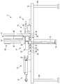
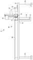
図1と図2に示すように、シート折り畳み装置11は、基台12と、基台12上でシート13を間に挟んだ両側の位置に設けられる第1の折り機構14および第2の折り機構15と、第1の折り機構14と第2の折り機構15とを近づけたり遠ざけたりする進退機構16と、第1の折り機構14および第2の折り機構15の扇形を閉じる方向にこれらを付勢する閉じ機構17と、基台12の下方に設けられるとともに、円筒形の煙草18を支持する支持台19と、第1の折り機構14および第2の折り機構15により折り畳まれたシート13を煙草18の先端部に押し込むためのプッシャ20と、第1の折り機構14および第2の折り機構15の位置を決めるための位置決めピン21と、を備えている。
基台12は、方形の板状に形成されている。基台12は、4本の脚部12Aを有している。また、基台12は、中央部に、第1の折り機構14および第2の折り機構15によって折り畳まれたシート13を下方に通すための円形の通し孔22を有している。
進退機構16は、例えば、エアシリンダ等で構成されている。また、閉じ機構17は、第1の折り機構14および第2の折り機構15によって折り畳まれたシート13を簡単に束ねるためのプレ成形ガイド26と、プレ成形ガイド26によって束ねられたシート13を円筒形に成形する成形ガイド27と、を有している。
図3に示すように、プレ成形ガイド26および成形ガイド27は、第1の折り機構14および第2の折り機構15が進退する方向とは直交する方向にスライド移動可能になっている。
プレ成形ガイド26は、第1のリニアガイド31と、第1のリニアガイド31によってスライド移動可能な一対の第1のガイド本体32と、を有している。第1のリニアガイド31は、第1のレール33と、第1のレール33上をスライドする第1のスライダ34(ベアリング)と、を有している。第1のガイド本体32は、平板状に形成されている。第1のガイド本体32は、略半円形の第1の切欠部35を有し、第1の切欠部35は、相手方の第1のガイド本体32の第1の切欠部35と共同して、端部が半円形になった長孔を形成する。
成形ガイド27は、第2のリニアガイド36と、第2のリニアガイド36によってスライド移動可能な一対の第2のガイド本体45と、を有している。第2のリニアガイド36は、第2のレール37と、第2のレール37上をスライドする第2のスライダ38(ベアリング)と、を有している。第2のガイド本体45は、平板状に形成されている。第2のガイド本体45は、半円形の第2の切欠部39を有し、第2の切欠部39は、相手方の第1のガイド本体32の第1の切欠部35と共同して、円形の貫通孔を形成する。なお、成形ガイド27は、位置決めピン21の外周部に当接して、第2のガイド本体45の位置を決めるための当接凹部40を有している。
なお、本実施形態において、成形ガイド27およびプレ成形ガイド26は、いずれも手動によって移動するようにしているが、これに限定されるものではない。成形ガイド27およびプレ成形ガイド26は、例えば、ボールねじを介したモータの駆動によって、自動で動作させるようにしてもよい。
図2に示すように、プッシャ20は、成形ガイド27およびプレ成形ガイド26の上方に配置されている。プッシャ20は、成形ガイド27およびプレ成形ガイド26の上方に固定された第3のリニアガイド41と、第3のリニアガイド41によって上昇および下降が可能な軸部本体42と、を有している。第3のリニアガイド41は、第3のレール43と、第3のレール43上をスライドする第3のスライダ44(ベアリング)とを有している。第3のスライダ44に軸部本体42が固定される。さらに、プッシャ20は、第3のスライダ44の移動を駆動するための図示しないモータと、モータの駆動力を第3のスライダ44に伝達するボールねじとを有している。
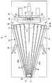
図1に示すように、第1の折り機構14および第2の折り機構15は、それぞれ扇形に展開して設けられている。第1の折り機構14は、複数の爪部47と、複数の爪部47を回動可能に支持する第1の支持部48と、複数の爪部47の先端部にそれぞれ固定された一枚の第1の帯状部材49と、を有している。爪部47は、例えば金属材料によって、長方形の平板状、すなわち短冊状に形成されている。爪部47は、金属製のものに限定されるものではなく、合成樹脂によって形成されていてもよい。第1の折り機構14は、奇数、例えば、9個の爪部47を有している。図3と図4に示すように、第1の支持部48は、「コ」字状をなした支持部本体50と、9個の爪部47に対応する9個の軸部51を有している。支持部本体50は、9個の軸部51の上端および下端が通される計18個の貫通孔52を有している。図4に示すように、9個の軸部51は、シート13の延びる方向と平行な方向Lに沿って互い違いの位置、つまり千鳥状に配置されている。
貫通孔52の内側に嵌っている軸部51は、それぞれ爪部47を回転可能に支持することができる。第1の支持部48は、軸部51を介して、複数の爪部47同士が分離して扇形に展開した第1の位置P1と、複数の爪部47同士が接触するように閉じた第2の位置P2との間で回動するように、複数の爪部47の一端を支持している。
第1の帯状部材49は、例えば綿布であるが、これに限定されるものではない。第1の帯状部材49は、伸縮しない材質であればよく、例えば、不織布等の樹脂製の布でもよい。第1の帯状部材49は、複数の爪部47が開いた第1の位置P1にあるときに円弧状に展開する。図1に示すように、第1の帯状部材49によって結ばれた爪部47の先端部同士の間隔は、扇形の外側に行くにつれて小さくなっている。
第2の折り機構15は、複数の爪部47と、複数の爪部47を回動可能に支持する第2の支持部55と、複数の爪部47の先端部にそれぞれ固定された一枚の第2の帯状部材56と、を有している。爪部47は、第1の折り機構14のものと同様の材質で形成され、同様の形態を有している。第2の折り機構15は、偶数、例えば、8個の爪部47を有している。第2の支持部55は、支持部本体50と、8個の爪部47に対応する8個の軸部51を有している。支持部本体50は、8個の軸部51の上端と下端とが通される計16個の貫通孔52を有している。第1の折り機構14のものと同様に、8個の軸部51は、シート13の延びる方向と平行な方向に沿って互い違い、すなわち千鳥状に配置されている。
貫通孔52の内側に嵌っている軸部51は、それぞれ爪部47を回転可能に支持することができる。第2の支持部55は、軸部51を介して、複数の爪部47同士が分離して扇形に展開した第1の位置P1と、複数の爪部47同士が接触するように閉じた第2の位置P2との間で回動するように、複数の爪部47の一端を支持する。第2の帯状部材56は、第1の帯状部材49と同じ材質ものであり、複数の爪部47が開いた第1の位置P1にあるときに円弧状に展開する。図1に示すように、第2の帯状部材56によって結ばれた爪部47の先端部同士の間隔は、扇形の外側に行くにつれて小さくなっている。
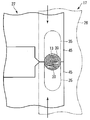
位置決めピン21は、円柱形状に形成されている。位置決めピン21は、その中央部にスリット57を有する。スリット57の内側に、第1の折り機構14の中央部に位置する爪部47がスライド可能に保持されている。このスリット57によって、第1の折り機構14の位置がずれないようになっている。本実施形態において、折り畳みに使用されるシート13は、例えば、カーボンフィルムであり、引っ張り方向の張力に対して脆弱性を有している。
シート13は、例えば、10mmの幅を有している。これに対して、第1の折り機構14および第2の折り機構15の爪部47、および第1の帯状部材49および第2の帯状部材56は、例えば、6mmの幅を有している。シート13の上端部および下端部には、第1の帯状部材49および第2の帯状部材56に接触しないマージン領域がそれぞれ2mmずつ形成されるが、このマージン領域は、プレ成形ガイド26で保持する際の重ね代として利用される。
続いて、図1、図5~図8を参照して、本実施形態のシート折り畳み装置11を利用したシート折り畳み方法について説明する。まず、図1に示すように、第1の折り機構14および第2の折り機構15の間の位置にシート13を配置する。そして、進退機構16を駆動して、第1の折り機構14および第2の折り機構15を互いに接近させる。これによって、シート13に対して第1の帯状部材49と第2の帯状部材56とが密着する。この状態では、図5に示すように、シート13、第1の帯状部材49、および第2の帯状部材56が蛇行するようにジグザグ形に配置する。この状態で、図6に示すように、プレ成形ガイド26の第1のガイド本体32同士が第1の折り機構14および第2の折り機構15が進退する方向と直交する方向から接近して、互いに突き合わされる。これによって、シート13、第1の帯状部材49、および第2の帯状部材56は、シート13の延びる方向に沿って軽く押しつぶされる。なお、図6では、第1の帯状部材49および第2の帯状部材56の図示を省略している。
続いて、進退機構16が駆動して第1の折り機構14および第2の折り機構15が後退して、互いに分離する。このとき、シート13の上端および下端は、プレ成形ガイド26の第1のガイド本体32によって保持されているため、シート13が再び展開してしまうことはない。シート13をプレ成形ガイド26によって保持した状態で、図7に示すように、成形ガイド27の第2のガイド本体45を第1の折り機構14および第2の折り機構15が進退する方向と直交する方向から接近させ、互いに突き合わされる。こうして、ジグザグ形に配置していたシート13はさらにシート13の延びる方向に押しつぶされて、蛇腹状に折り畳まれる。この状態で、プッシャ20によって上方から下方に向けて押し込まれることで、シート13は、図8に示すように、支持台19に支持された煙草18の円筒形の外筒部18Aの内側に差し込まれる。
このとき、シート13は、直線状の折り目(折り返し)が形成されることない。また、第1の支持部48および第2の支持部55の複数の軸部51が千鳥状に配置されるため、爪部47の先端部の位置も千鳥状になり、その結果折り畳まれるシート13は、折り目となるアーチ部分の位置が互い違いになるように位置ずれしている(図8参照)。
第1の実施形態によれば、シート折り畳み装置11は、シート13を間に挟んだ両側の位置で、扇形に展開した第1の折り機構14および第2の折り機構15と、第1の折り機構14と第2の折り機構15とを互いに接近させたり、遠ざけたりする進退機構16と、扇形を閉じる方向に第1の折り機構14および第2の折り機構15を付勢する閉じ機構17と、を具備し、第1の折り機構14および第2の折り機構15は、平板状をなした複数の爪部47と、複数の爪部47同士が分離して扇形に展開した第1の位置P1と、複数の爪部47同士が接触するように閉じた第2の位置P2との間で回動するように複数の爪部47の一端を支持する支持部と、複数の爪部47の先端部にそれぞれ固定され、シート13に直接接触するとともに、複数の爪部47が第1の位置P1にあるときに円弧状に展開する帯状部材と、をそれぞれ有し、進退機構16は、第1の折り機構14の爪部47の先端部と、第2の折り機構15の爪部47の先端部と、がオーバーラップする位置まで第1の折り機構14と第2の折り機構15とを前進させ、閉じ機構17は、複数の爪部47を第1の位置P1から第2の位置P2に移動させ、帯状部材とともにシート13を蛇腹状に折り畳む。
また、第1の実施形態のシート折り畳み方法によれば、シート13を間に挟んだ両側に配置されるとともにそれぞれ扇形をなした第1の折り機構14および第2の折り機構15を互いに接近させることで、第1の折り機構14に円弧状に設けられる第1の帯状部材49と第2の折り機構15に円弧状に設けられる第2の帯状部材56とをそれぞれシート13に密着させるとともに、扇形の半径方向に沿って第1の折り機構14に設けられる複数の爪部47の先端部と、扇形の半径方向に沿って第2の折り機構15に設けられる複数の爪部47の先端部と、がオーバーラップするように配置させ、シート13、第1の帯状部材49、および第2の帯状部材56をジグザグ形に配置した後、シート13の延びる方向に沿ってシート13、第1の帯状部材49、および第2の帯状部材56を押しつぶすことにより、シート13を蛇腹状に折り畳む。
これらの構成によれば、シート13を順次折るのではなく、第1の折り機構14および第2の折り機構15によって複数の箇所を同時に折り畳むことができるため、折り畳み作業を簡単かつ一括して迅速に行うことができる。また、シート13に密着した帯状部材がシート13とともに折り畳まれるため、シート13に対して爪部47が滑るようなことなく、シート13の一箇所に張力が集中してしまうことがない。このため、張力に対して脆弱なシート13を折り畳む場合等に、シート13の一部に負荷が掛かることなく、シート13をやさしく折り畳むことができる。さらに、シート13とともに第1の帯状部材49および第2の帯状部材56が折り畳まれるため、シート13を傷つけるような強い折り目がシート13についてしまうこともなく、アーチ状の折り目を有するようにシート13をやさしく折りたたむことができる。
また、第1の折り機構14の複数の爪部47および第2の折り機構15の複数の爪部47のいずれか一方は、奇数で構成されるとともに、第1の折り機構14の複数の爪部47および第2の折り機構15の複数の爪部47のいずれか他方は、偶数で構成される。この構成によれば、爪部47同士の間の位置に相手方の折り機構の爪部47を配置させることができる。これによって、シート13をジグザグ形に配置することができ、簡単な閉じ操作でシート13を蛇腹状に折り畳むことができる。
また、複数の爪部47は、互いに同一の寸法に形成され、支持部は、複数の爪部47に対応する複数の軸部51を含み、軸部51は、それぞれ爪部47を回転可能に支持し、複数の軸部51は、シート13の延びる方向と平行な方向Lに沿って千鳥状に配置される。この構成によれば、シート13のアーチ状の折り目を互い違いの位置に配置させることができる。これによって、折り目の部分同士が干渉してしまうことを防いで、折り目の部分においてシート13が急角度で折り曲げられて、シート13を痛めてしまうことを防止できる。また、特に本実施形態のように、カーボンフィルムをシート13として用い、このカーボンフィルムを煙草18の加熱源として利用する場合には、シート13同士の隙間を十分に確保することができ、空気の流れる流路を確保するのに特に有効である。
また、本実施形態において、帯状部材によって結ばれる複数の爪部47の先端部同士の間隔は、扇形の外側に行くにつれて小さくなる。この構成によれば、シート13の両端部に行くにつれて折り畳みの間隔を小さくするような折り畳み方法を簡単な構造で実現することができる。これによって、例えば、本実施形態のように、円筒形の煙草18の外筒部18Aにシート13を挿入する場合など、円形の小さいスペースにコンパクトに収容するのに特に有効である。
続いて、図9から図12を参照して、シート折り畳み装置の第2の実施形態について説明する。第2の実施形態のシート折り畳み装置61は、1つの折り機構62を用いる点、吸引機構が設けられている点、折り機構62に対抗する吸引ブロック64が設けられる点などにおいて第1の実施形態と異なっているが、他の部分は第1の実施形態と共通している。このため、ここでは、主として第1の実施形態と異なる点について説明し、第1の実施形態と共通する箇所には共通の符号を付して説明を省略する。
図9と図10に示すように、シート折り畳み装置61は、基台12と、基台12上に設けられる1つの折り機構62と、折り機構62を真空状態に吸引するための第1の吸引機構63と、折り機構62に正対する吸引ブロック64と、吸引ブロック64を吸引するための図示しない第2の吸引機構と、吸引ブロック64を進退させるための進退機構16と、シート13を円筒形に成形するための成形ガイド27と、基台12の下方に設けられるとともに、円筒形の煙草18を支持する支持台19と、第1の折り機構14および第2の折り機構15により折り畳まれたシート13を煙草の先端部に押し込むためのプッシャ20と、を有している。第1の吸引機構63および第2の吸引機構は、例えば真空ポンプ等で構成される。
シート折り畳み装置61は、さらに、ガイド溝66と、ガイド溝66の内側に引っ掛けられるワイヤ67と、を折り機構62の両側の位置にそれぞれ有している。ガイド溝66およびワイヤ67は、第1の吸引機構63による吸引によって、折り機構62の閉じる速度を低減して、シート13が急速に折り畳まれてしまうことを防止する。シート折り畳み装置61は、第1の吸引機構63の吸引力をシート13に効率よく作用させるためのブロック68を、シート13の両端部の近傍に一対に有している。
成形ガイド27は、第1の実施形態の成形ガイド27とほぼ同様の構成であり、例えば、半円形の切欠部39を有するガイド本体45を一対に有している。プッシャ20は、第1の実施形態のものと同一である。
図9に示すように、折り機構62は、複数の爪部47と、複数の爪部47を回動可能に支持する支持部48と、複数の爪部47の先端部にそれぞれ固定された一枚の帯状部材49と、複数の爪部47同士の間の空間を密閉する密閉部材69と、を有している。折り機構62は、例えば、9個の爪部47を有している。爪部47は、それぞれ短冊状に形成されている。爪部47は、例えば金属材料によって、平板状に形成されている。爪部47は、合成樹脂によって形成されていてもよい。また、扇形の外側の端部に位置する爪部47は、補強のため、それぞれ外側に折り曲げられた折り曲げ部47Aを有している。爪部47は、その先端部の近傍に、スペーサ72を有している。スペーサ72は、爪部47の先端同士が接近しすぎることを回避して、シート13に強い折り目が形成されてしまうことを防止する。
支持部48は、支持部本体50と、9個の爪部47に対応する9個の軸部51を有している。支持部本体50は、9個の軸部51の上端および下端が通される計18個の貫通孔52を有している。図9に示すように、9個の軸部51は、シート13の延びる方向と平行な方向に沿って互い違い、すなわち千鳥状に配置されている。また、支持部本体50の内側は、中空になっており、上記第1の吸引機構63に連通している連通穴73を有している。
貫通孔52の内側に嵌っている軸部51は、それぞれ爪部47を回転可能に支持することができる。支持部48は、軸部51を介して、複数の爪部47同士が分離して扇形に展開した第1の位置P1と、複数の爪部47同士が接触するように閉じた第2の位置P2との間で回動するように、複数の爪部47の一端を支持する。
帯状部材49は、例えばナイロン等のメッシュ状の繊維であるが、これに限定されるものではない。帯状部材49は、開口度の大きいメッシュ状の材質であればよい。帯状部材49は、複数の爪部47が開いた第1の位置P1にあるときに円弧状に展開する。図9に示すように、帯状部材49によって結ばれた爪部47の先端部同士の間隔は、扇形の外側に行くにつれて小さくなっている。
密閉部材69は、複数の爪部47の上側に配置された平板状のプレートである。爪部47同士の間にある空間部分は、このプレートと基台12との間で挟まれた密閉空間となる。吸引ブロック64は、シート13に吸引力を作用させるためのスリット状の吸引孔74を有している。吸引ブロック64は、中空になった内部空間を有しており、この内部空間は、第2の吸引機構65に連通されている。
続いて、図9から図12を参照して、第2の実施形態のシート折り畳み装置61を利用したシート折り畳み方法について説明する。まず、図9に示すように、折り機構62および吸引ブロック64の間の位置にシート13を配置する。このとき、折り機構62は、扇形に展開している。続いて、第1の吸引機構63を駆動して、折り機構62およびシート13に対して吸引力を作用させる。これによって、シート13は、帯状部材49に密着する。また、第1の吸引機構63によって、爪部47同士の間の空間の空気が吸引され、折り機構62は、図11に示すように閉じられる。こうして、帯状部材49に密着されたシート13は、帯状部材49とともに蛇腹状に折り畳まれる。なお、図11ではシート13の図示を省略している。なお、スペーサ72の作用によって、爪部47の先端同士が付き合わされることが防止されている。
そして、進退機構16が駆動して、吸引ブロック64を折り機構62に近づける。また、第2の吸引機構65を駆動して吸引ブロック64に吸引力を発生させる。これと同時に、第1の吸引機構63である真空ポンプを逆回転させて正圧の空気を送って、折り機構62の真空状態を破壊して、帯状部材49からシート13を分離させる。このとき、シート13は、吸引ブロック64の吸引孔74に密着し、蛇腹状に折り畳まれた状態で保持される。そして、図12に示すように、成形ガイド27のガイド本体45同士が突き当たるように移動して、シート13を円筒形に成形する。このように成形されたシート13は、第1の実施形態と同様に、プッシャ20によって下方に押しこまれて、煙草18の円筒形の外筒部18Aの内側に挿入される。
第2の実施形態によれば、シート折り畳み装置61は、平板状をなした複数の爪部47と、複数の爪部47同士が分離して扇形に展開した第1の位置P1と、複数の爪部47同士が接触するように閉じた第2の位置P2との間で回動するように複数の爪部47の一端を支持する支持部48と、複数の爪部47の先端部にそれぞれ固定され、シート13に直接接触するとともに、複数の爪部47が第1の位置P1にあるときに円弧状に展開する帯状部材49と、複数の爪部47同士と、帯状部材49とで囲まれる空間を密閉する密閉部材69と、空間の内部の空気を吸引する吸引機構と、を具備し、吸引機構は、空間の内部の空気を吸引して、帯状部材49とともにシート13を蛇腹状に折り畳む。
この構成によれば、折り機構62を1つのみ有する構成であっても、シート13を一括して効率よく蛇腹状に折り畳むことができる。また、シート13は、帯状部材49に密着された状態で折り畳まれるため、シート13に対して爪部47が滑ってしまうことがない。このため、張力に対して脆弱なシート13を折り畳む場合等に、シート13の一部に負荷をかけることなく、シート13をやさしく折り畳むことができる。また、シート13とともに帯状部材が折り畳まれるため、シート13に強い折り目がついてしまうことを防いで、シート13をやさしく折り畳むことができる。
また、爪部47は、隣接する他の爪部47との間で所定の隙間を確保するためのスペーサ72を先端部の近傍に有する。この構成によれば、爪部47同士が突き当たることを防いで、シート13に強い折り目(折り返し)が形成されて、シート13を痛めてしまうことを防止できる。
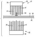
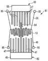
続いて、図13から図16を参照して、シート折り畳み装置の第3の実施形態について説明する。第3の実施形態のシート折り畳み装置81は、第1の折り機構82および第2の折り機構83の構成が異なる点等において第1の実施形態と異なっているが、他の部分は第1の実施形態と共通している。このため、ここでは、主として第1の実施形態と異なる点について説明し、第1の実施形態と共通する箇所には共通の符号を付して説明を省略する。なお、第3の実施形態では、基台12、進退機構16、閉じ機構17、プッシャ20、支持台19は、第1の実施形態のものと同一であるため、その図示を省略している。
シート折り畳み装置81は、シート13を間に挟んだ両側の位置に設けられる第1の折り機構82および第2の折り機構83と、第1の折り機構82と第2の折り機構83とを近づけたり遠ざけたりする進退機構16と、シート13の一方の面に対向して配置された第1の帯状部材49と、シート13の他方の面に対向して配置された第2の帯状部材56と、シート13の位置ずれを防止するための保持機構84と、を備えている。第1の帯状部材49および第2の帯状部材56は、ばね機構85によって、図13における左右方向の両側から引っ張られた状態で保持されている。保持機構84は、シート13とほぼ同一の幅を有する平板状の形状を有している。
図13に示すように、第1の折り機構82は、第1の支持部48と、第1の支持部48に対して櫛歯状に固定される複数の爪部47と、を有している。爪部47は、例えば金属材料によって平板状に形成されている。爪部47は、合成樹脂によって形成されていてもよい。第1の折り機構82は、奇数、例えば、9個の爪部47を有している。9個の爪部47は、互いの長さが若干異なっており、爪部47の先端部の高さが互い違い(千鳥状)になるように長さが調整されている。
第2の折り機構83は、第2の支持部55と、第1の支持部48に対して櫛歯状に固定される複数の爪部47と、を有している。爪部47は、金属材料によって、平板状に形成されている。第2の折り機構83は、偶数、例えば、8個爪部47を有している。8個の爪部47は、互いの長さが若干異なっており、爪部47の先端部の高さが互い違い(千鳥状)になるように長さが調整されている。
第1の帯状部材49および第2の帯状部材56は、例えば高分子プラスチック製の繊維であるが、これに限定されるものではない。第1の帯状部材49は、例えば、カーボン繊維、ナイロン、フッ素樹脂製の繊維でもよい。第2の帯状部材56は、第1の帯状部材49と同じ材質ものである。
続いて、図13から図16を参照して、本実施形態のシート折り畳み装置81を利用したシート折り畳み方法について説明する。まず、図13に示すように、第1の折り機構82および第2の折り機構83の間の位置にシート13を配置する。このとき、第1の帯状部材49および第2の帯状部材56には、ばね機構85の張力が作用している。そして、図14に示すように、保持機構84が先に移動して、シート13、第1の帯状部材49、および第2の帯状部材56を間に挟んで、第1の折り機構82の中央部にある爪部47の先端部に突き当たる。保持機構84が爪部47の先端部に突き当たることによって、シート13の中央部の位置が固定され、シート13が左右方向にずれてしまうことが防止される。なお、保持機構84は、第1の折り機構82に突き当たるものに限定されるものでなく、第2の折り機構83の中央部にある爪部47の先端部に突き当たるようにしてもよい。
そして、進退機構16の駆動で第1の折り機構82と第2の折り機構83とが接近して、図15に示すように、互いの爪部47の先端部がオーバーラップする位置まで接近する。これによって、第1の折り機構82および第2の折り機構83の間の位置にあるシート13は、第1の帯状部材49および第2の帯状部材56とともに蛇腹状に折り込まれる。このとき、第1の折り機構82の爪部47および第2の折り機構83の爪部47は、第1の帯状部材49および第2の帯状部材56に対して滑るように作用するが、シート13と第1の帯状部材49との間、およびシート13と第2の帯状部材56との間には、滑りは生じない。
図16に示すように、進退機構16が駆動して、第1の折り機構82と第2の折り機構83とが分離する。このとき、シート13は、図示しない閉じ機構のプレ成形ガイドに保持される。その後は、第1の実施形態と同様の工程で、プレ成形ガイド、成形ガイド、およびプッシャの作用によって煙草18の円筒形の外筒部18Aの内側にシート13が挿入される。
第3の実施形態によれば、シート折り畳み装置81は、シート13を間に挟んだ両側で、シート13に接触するように設けられる第1の帯状部材49および第2の帯状部材56と、シート13、第1の帯状部材49、および第2の帯状部材56を間に挟んだ両側に配置される第1の折り機構82および第2の折り機構83と、第1の折り機構82と第2の折り機構83とを互いに接近させたり、遠ざけたりする進退機構16と、を具備し、第1の折り機構82および第2の折り機構83は、支持部と、平板状をなすとともに、支持部に対して櫛歯状に固定される複数の爪部47と、をそれぞれ有し、進退機構16は、第1の折り機構82の爪部47の先端部と、第2の折り機構83の爪部の先端部と、がオーバーラップする位置まで第1の折り機構82と第2の折り機構83とを前進させ、第1の帯状部材49および第2の帯状部材56とともにシート13を蛇腹状に折り畳む。
この構成によれば、第1の帯状部材49および第2の帯状部材56ととともにシート13が折りたたまれるため、第1の帯状部材49および第2の帯状部材56に対して第1の折り機構82および第2の折り機構83の複数の爪部47が滑るように作用するが、シート13と第1の帯状部材49および第2の帯状部材56との間では滑りを生じない。このため、シート13に対して張力が集中することがなく、シート13を一括して蛇腹状に折りたたむことができる。また、シート13とともに第1の帯状部材49および第2の帯状部材56とが折り畳まれるため、シート13に強い折り目がついてしまうことを防止できる。
また、シート折り畳み装置81は、第1の折り機構82および第2の折り機構83の複数の爪部47のうち、少なくとも1つの爪部47との間でシート13、第1の帯状部材49、および第2の帯状部材56を挟んで保持する保持機構84をさらに具備する。
この構成によれば、保持機構84によって第1の折り機構82および第2の折り機構83に対してシート13の位置を固定することができる。これによって、第1の折り機構82および第2の折り機構83が互いに近づいてシート13を折りたたむ際に、シート13の位置がずれてしまうことを防止することができる。
本発明のシート折り畳み装置81は、上記した非燃焼型の煙草のほか、昆布、海苔、チューインガム、パスタといった食品の折り畳みや、コンデンサの折り畳み、電池に用いられる電極の折り畳み、有機EL装置等のシート状の表示装置等の折り畳みにも用いることができる。このとき、折り畳まれる対象の製品に折り目をつけることなく、コンパクトに収容することができる。このほか、本発明は、発明の要旨を逸脱しない範囲で種々変形実施可能であるのは勿論である。
Claims (12)
- シートを間に挟んだ両側の位置で、扇形に展開した第1の折り機構および第2の折り機構と、
前記第1の折り機構と前記第2の折り機構とを互いに接近させたり、遠ざけたりする進退機構と、
前記扇形を閉じる方向に前記第1の折り機構および前記第2の折り機構を付勢する閉じ機構と、
を具備し、
前記第1の折り機構および前記第2の折り機構は、
平板状をなした複数の爪部と、
前記複数の爪部同士が分離して前記扇形に展開した第1の位置と、前記複数の爪部同士が接触するように閉じた第2の位置との間で回動するように前記複数の爪部の一端を支持する支持部と、
前記複数の爪部の先端部にそれぞれ固定され、前記シートに直接接触するとともに、前記複数の爪部が前記第1の位置にあるときに円弧状に展開する帯状部材と、
をそれぞれ有し、
前記進退機構は、前記第1の折り機構の前記爪部の先端部と、前記第2の折り機構の前記爪部の先端部と、がオーバーラップする位置まで前記第1の折り機構と前記第2の折り機構とを前進させ、前記閉じ機構は、前記複数の爪部を前記第1の位置から前記第2の位置に移動させ、前記帯状部材とともに前記シートを蛇腹状に折り畳むことを特徴とするシート折り畳み装置。 - 前記第1の折り機構の複数の爪部および前記第2の折り機構の複数の爪部のいずれか一方は、奇数で構成されるとともに、前記第1の折り機構の複数の爪部および前記第2の折り機構の複数の爪部のいずれか他方は、偶数で構成されることを特徴とする請求項1に記載のシート折り畳み装置。
- 前記複数の爪部は、互いに同一の寸法に形成され、
前記支持部は、前記複数の爪部に対応する複数の軸部を含み、前記軸部は、それぞれ前記爪部を回転可能に支持し、
前記複数の軸部は、前記シートの延びる方向と平行な方向に沿って千鳥状に配置されることを特徴とする請求項2に記載のシート折り畳み装置。 - 前記帯状部材によって結ばれる前記複数の爪部の先端部同士の間隔は、前記扇形の外側に行くにつれて小さくなることを特徴とする請求項3に記載のシート折り畳み装置。
- 平板状をなした複数の爪部と、
前記複数の爪部同士が分離して前記扇形に展開した第1の位置と、前記複数の爪部同士が接触するように閉じた第2の位置との間で回動するように前記複数の爪部の一端を支持する支持部と、
前記複数の爪部の先端部にそれぞれ固定され、前記シートに直接接触するとともに、前記複数の爪部が前記第1の位置にあるときに円弧状に展開する帯状部材と、
前記複数の爪部同士と、前記帯状部材とで囲まれる空間を密閉する密閉部材と、
前記空間の内部の空気を吸引する吸引機構と、
を具備し、
前記吸引機構は、前記空間の内部の空気を吸引して、前記帯状部材とともに前記シートを蛇腹状に折り畳むことを特徴とするシート折り畳み装置。 - 前記複数の爪部は、互いに同一の寸法に形成され、
前記支持部は、前記複数の爪部に対応する複数の軸部を含み、前記軸部は、それぞれ前記爪部を回転可能に支持し、
前記複数の軸部は、前記シートの延びる方向と平行な方向に沿って千鳥状に配置されることを特徴とする請求項5に記載のシート折り畳み装置。 - 前記帯状部材によって結ばれる前記複数の爪部の先端部同士の間隔は、前記扇形の外側に行くにつれて小さくなることを特徴とする請求項6に記載のシート折り畳み装置。
- 前記爪部は、隣接する他の爪部との間で所定の隙間を確保するためのスペーサを前記先端部の近傍に有することを特徴とする請求項7に記載のシート折り畳み装置。
- シートを間に挟んだ両側で、前記シートに接触するように設けられる第1の帯状部材および第2の帯状部材と、
前記シート、前記第1の帯状部材、および前記第2の帯状部材を間に挟んだ両側に配置される第1の折り機構および第2の折り機構と、
前記第1の折り機構と前記第2の折り機構とを互いに接近させたり、遠ざけたりする進退機構と、
を具備し、
前記第1の折り機構および前記第2の折り機構は、
支持部と、
平板状をなすとともに、前記支持部に対して櫛歯状に固定される複数の爪部と、
をそれぞれ有し、
前記進退機構は、前記第1の折り機構の前記爪部の先端部と、前記第2の折り機構の前記爪部の先端部と、がオーバーラップする位置まで前記第1の折り機構と前記第2の折り機構とを前進させ、前記第1の帯状部材および前記第2の帯状部材とともに前記シートを蛇腹状に折り畳むことを特徴とするシート折り畳み装置。 - 前記第1の折り機構の複数の爪部および前記第2の折り機構の複数の爪部のいずれか一方は、奇数で構成されるとともに、前記第1の折り機構の複数の爪部および前記第2の折り機構の複数の爪部のいずれか他方は、偶数で構成されることを特徴とする請求項9に記載のシート折り畳み装置。
- 前記第1の折り機構の前記複数の爪部および前記第2の折り機構の前記複数の爪部のうち、少なくとも1つの前記爪部との間で前記シート、前記第1の帯状部材、および前記第2の帯状部材を挟んで保持する保持機構をさらに具備することを特徴とする請求項10に記載のシート折り畳み装置。
- シートを間に挟んだ両側に配置されるとともにそれぞれ扇形をなした第1の折り機構および第2の折り機構を互いに接近させることで、前記第1の折り機構に円弧状に設けられる第1の帯状部材と前記第2の折り機構に円弧状に設けられる第2の帯状部材とをそれぞれ前記シートに密着させるとともに、前記扇形の半径方向に沿って前記第1の折り機構に設けられる複数の爪部の先端部と、前記扇形の半径方向に沿って前記第2の折り機構に設けられる複数の爪部の先端部と、がオーバーラップするように配置させ、前記シート、前記第1の帯状部材、および前記第2の帯状部材をジグザグ形に配置した後、前記シートの延びる方向に沿って前記シート、前記第1の帯状部材、および前記第2の帯状部材を押しつぶすことにより、前記シートを蛇腹状に折り畳むことを特徴とするシート折り畳み方法。
Applications Claiming Priority (2)
| Application Number | Priority Date | Filing Date | Title |
|---|---|---|---|
| JP2008302832A JP5015122B2 (ja) | 2008-11-27 | 2008-11-27 | シート折り畳み装置およびシート折り畳み方法 |
| JP2008-302832 | 2008-11-27 |
Publications (1)
| Publication Number | Publication Date |
|---|---|
| WO2010061693A1 true WO2010061693A1 (ja) | 2010-06-03 |
Family
ID=42225573
Family Applications (1)
| Application Number | Title | Priority Date | Filing Date |
|---|---|---|---|
| PCT/JP2009/067866 Ceased WO2010061693A1 (ja) | 2008-11-27 | 2009-10-15 | シート折り畳み装置およびシート折り畳み方法 |
Country Status (3)
| Country | Link |
|---|---|
| JP (1) | JP5015122B2 (ja) |
| TW (1) | TW201020143A (ja) |
| WO (1) | WO2010061693A1 (ja) |
Cited By (1)
| Publication number | Priority date | Publication date | Assignee | Title |
|---|---|---|---|---|
| CN119142901A (zh) * | 2024-11-19 | 2024-12-17 | 泉州市华讯机械制造有限公司 | 一种餐用纸巾折叠设备 |
Families Citing this family (2)
| Publication number | Priority date | Publication date | Assignee | Title |
|---|---|---|---|---|
| CN103010146A (zh) * | 2013-01-07 | 2013-04-03 | 延锋百利得(上海)汽车安全系统有限公司 | 一种汽车安全气囊装置及其折叠工装 |
| CN113955569B (zh) * | 2021-08-19 | 2025-09-19 | 武汉大润科技有限公司 | 一种下落式雨布折叠回收装置及回收方法 |
Citations (4)
| Publication number | Priority date | Publication date | Assignee | Title |
|---|---|---|---|---|
| JPH0687392A (ja) * | 1992-09-08 | 1994-03-29 | Toyoda Gosei Co Ltd | エアバッグの折り畳み方法 |
| JPH10218484A (ja) * | 1997-02-12 | 1998-08-18 | Toyoda Gosei Co Ltd | エアバッグ折り機 |
| JPH11129847A (ja) * | 1997-11-04 | 1999-05-18 | Kansei Corp | エアバッグ折り畳み装置 |
| JP2002019561A (ja) * | 2000-07-06 | 2002-01-23 | Nippon Plast Co Ltd | エアバッグの折畳装置及びエアバッグの折畳方法 |
-
2008
- 2008-11-27 JP JP2008302832A patent/JP5015122B2/ja active Active
-
2009
- 2009-10-15 WO PCT/JP2009/067866 patent/WO2010061693A1/ja not_active Ceased
- 2009-10-26 TW TW98136114A patent/TW201020143A/zh unknown
Patent Citations (4)
| Publication number | Priority date | Publication date | Assignee | Title |
|---|---|---|---|---|
| JPH0687392A (ja) * | 1992-09-08 | 1994-03-29 | Toyoda Gosei Co Ltd | エアバッグの折り畳み方法 |
| JPH10218484A (ja) * | 1997-02-12 | 1998-08-18 | Toyoda Gosei Co Ltd | エアバッグ折り機 |
| JPH11129847A (ja) * | 1997-11-04 | 1999-05-18 | Kansei Corp | エアバッグ折り畳み装置 |
| JP2002019561A (ja) * | 2000-07-06 | 2002-01-23 | Nippon Plast Co Ltd | エアバッグの折畳装置及びエアバッグの折畳方法 |
Cited By (1)
| Publication number | Priority date | Publication date | Assignee | Title |
|---|---|---|---|---|
| CN119142901A (zh) * | 2024-11-19 | 2024-12-17 | 泉州市华讯机械制造有限公司 | 一种餐用纸巾折叠设备 |
Also Published As
| Publication number | Publication date |
|---|---|
| TW201020143A (en) | 2010-06-01 |
| JP2010126303A (ja) | 2010-06-10 |
| JP5015122B2 (ja) | 2012-08-29 |
Similar Documents
| Publication | Publication Date | Title |
|---|---|---|
| JP5015122B2 (ja) | シート折り畳み装置およびシート折り畳み方法 | |
| JP2009541148A5 (ja) | ||
| JP6458019B2 (ja) | タイヤビードエイペックスの把持及び取扱システム及び方法 | |
| KR20200016377A (ko) | 더니지 변환 장치 및 방법 | |
| JP2005001841A (ja) | 用紙折り装置、用紙処理装置および画像形成システム | |
| JP2008169003A (ja) | 線条体収束機構とそれを備えたテープ巻き装置及びテープ巻き方法 | |
| US843781A (en) | Apparatus for cutting, folding, and interfolding sheets or units. | |
| ATE446905T1 (de) | Papierzuführvorrichtung für eine umreifungsmaschine zur produktion von papierollen | |
| EP1925482A3 (de) | Verdeck für ein Cabriolet | |
| CN113710599B (zh) | 折入装置以及折入方法 | |
| JP2011225235A (ja) | 袋口結束装置 | |
| JP2010516520A (ja) | 回転式ステープラの方法及び装置 | |
| US5634875A (en) | Folding machine | |
| EP1209112A2 (en) | Guide apparatus for use in folder | |
| JP3577970B2 (ja) | 帯状布材の折り曲げ方法と装置 | |
| JP4805566B2 (ja) | 管状被包を製造するための方法及び装置 | |
| JP2012106762A (ja) | 袋口結束装置 | |
| CN214192094U (zh) | 一种助推式辅助回位的臂筒装置 | |
| US7067025B2 (en) | Machine for the production of air pillows used for packaging by means of a tubular film disposed on a reel | |
| US4290764A (en) | Method and apparatus for folding a cardboard sheet along a straight fold line | |
| KR200473127Y1 (ko) | 제대기 | |
| JP2005514245A5 (ja) | ||
| JP2007245650A (ja) | 後処理装置 | |
| JP3655091B2 (ja) | 結束機のテープ案内機構 | |
| US892837A (en) | Newspaper-wrapping machine. |
Legal Events
| Date | Code | Title | Description |
|---|---|---|---|
| 121 | Ep: the epo has been informed by wipo that ep was designated in this application |
Ref document number: 09828942 Country of ref document: EP Kind code of ref document: A1 |
|
| NENP | Non-entry into the national phase |
Ref country code: DE |
|
| 122 | Ep: pct application non-entry in european phase |
Ref document number: 09828942 Country of ref document: EP Kind code of ref document: A1 |