WO2010061577A1 - Dispositif d’affichage à cristaux liquides à couleurs primaires multiples et circuit de conversion de signaux - Google Patents
Dispositif d’affichage à cristaux liquides à couleurs primaires multiples et circuit de conversion de signaux Download PDFInfo
- Publication number
- WO2010061577A1 WO2010061577A1 PCT/JP2009/006319 JP2009006319W WO2010061577A1 WO 2010061577 A1 WO2010061577 A1 WO 2010061577A1 JP 2009006319 W JP2009006319 W JP 2009006319W WO 2010061577 A1 WO2010061577 A1 WO 2010061577A1
- Authority
- WO
- WIPO (PCT)
- Prior art keywords
- pixel
- sub
- red
- liquid crystal
- pixels
- Prior art date
Links
Images


Classifications
-
- G—PHYSICS
- G09—EDUCATION; CRYPTOGRAPHY; DISPLAY; ADVERTISING; SEALS
- G09G—ARRANGEMENTS OR CIRCUITS FOR CONTROL OF INDICATING DEVICES USING STATIC MEANS TO PRESENT VARIABLE INFORMATION
- G09G3/00—Control arrangements or circuits, of interest only in connection with visual indicators other than cathode-ray tubes
- G09G3/20—Control arrangements or circuits, of interest only in connection with visual indicators other than cathode-ray tubes for presentation of an assembly of a number of characters, e.g. a page, by composing the assembly by combination of individual elements arranged in a matrix no fixed position being assigned to or needed to be assigned to the individual characters or partial characters
- G09G3/34—Control arrangements or circuits, of interest only in connection with visual indicators other than cathode-ray tubes for presentation of an assembly of a number of characters, e.g. a page, by composing the assembly by combination of individual elements arranged in a matrix no fixed position being assigned to or needed to be assigned to the individual characters or partial characters by control of light from an independent source
- G09G3/36—Control arrangements or circuits, of interest only in connection with visual indicators other than cathode-ray tubes for presentation of an assembly of a number of characters, e.g. a page, by composing the assembly by combination of individual elements arranged in a matrix no fixed position being assigned to or needed to be assigned to the individual characters or partial characters by control of light from an independent source using liquid crystals
- G09G3/3611—Control of matrices with row and column drivers
- G09G3/3648—Control of matrices with row and column drivers using an active matrix
-
- G—PHYSICS
- G09—EDUCATION; CRYPTOGRAPHY; DISPLAY; ADVERTISING; SEALS
- G09G—ARRANGEMENTS OR CIRCUITS FOR CONTROL OF INDICATING DEVICES USING STATIC MEANS TO PRESENT VARIABLE INFORMATION
- G09G3/00—Control arrangements or circuits, of interest only in connection with visual indicators other than cathode-ray tubes
- G09G3/20—Control arrangements or circuits, of interest only in connection with visual indicators other than cathode-ray tubes for presentation of an assembly of a number of characters, e.g. a page, by composing the assembly by combination of individual elements arranged in a matrix no fixed position being assigned to or needed to be assigned to the individual characters or partial characters
- G09G3/34—Control arrangements or circuits, of interest only in connection with visual indicators other than cathode-ray tubes for presentation of an assembly of a number of characters, e.g. a page, by composing the assembly by combination of individual elements arranged in a matrix no fixed position being assigned to or needed to be assigned to the individual characters or partial characters by control of light from an independent source
- G09G3/36—Control arrangements or circuits, of interest only in connection with visual indicators other than cathode-ray tubes for presentation of an assembly of a number of characters, e.g. a page, by composing the assembly by combination of individual elements arranged in a matrix no fixed position being assigned to or needed to be assigned to the individual characters or partial characters by control of light from an independent source using liquid crystals
- G09G3/3607—Control arrangements or circuits, of interest only in connection with visual indicators other than cathode-ray tubes for presentation of an assembly of a number of characters, e.g. a page, by composing the assembly by combination of individual elements arranged in a matrix no fixed position being assigned to or needed to be assigned to the individual characters or partial characters by control of light from an independent source using liquid crystals for displaying colours or for displaying grey scales with a specific pixel layout, e.g. using sub-pixels
-
- G—PHYSICS
- G09—EDUCATION; CRYPTOGRAPHY; DISPLAY; ADVERTISING; SEALS
- G09G—ARRANGEMENTS OR CIRCUITS FOR CONTROL OF INDICATING DEVICES USING STATIC MEANS TO PRESENT VARIABLE INFORMATION
- G09G2300/00—Aspects of the constitution of display devices
- G09G2300/04—Structural and physical details of display devices
- G09G2300/0421—Structural details of the set of electrodes
- G09G2300/0426—Layout of electrodes and connections
-
- G—PHYSICS
- G09—EDUCATION; CRYPTOGRAPHY; DISPLAY; ADVERTISING; SEALS
- G09G—ARRANGEMENTS OR CIRCUITS FOR CONTROL OF INDICATING DEVICES USING STATIC MEANS TO PRESENT VARIABLE INFORMATION
- G09G2300/00—Aspects of the constitution of display devices
- G09G2300/04—Structural and physical details of display devices
- G09G2300/0439—Pixel structures
- G09G2300/0443—Pixel structures with several sub-pixels for the same colour in a pixel, not specifically used to display gradations
- G09G2300/0447—Pixel structures with several sub-pixels for the same colour in a pixel, not specifically used to display gradations for multi-domain technique to improve the viewing angle in a liquid crystal display, such as multi-vertical alignment [MVA]
-
- G—PHYSICS
- G09—EDUCATION; CRYPTOGRAPHY; DISPLAY; ADVERTISING; SEALS
- G09G—ARRANGEMENTS OR CIRCUITS FOR CONTROL OF INDICATING DEVICES USING STATIC MEANS TO PRESENT VARIABLE INFORMATION
- G09G2300/00—Aspects of the constitution of display devices
- G09G2300/04—Structural and physical details of display devices
- G09G2300/0439—Pixel structures
- G09G2300/0452—Details of colour pixel setup, e.g. pixel composed of a red, a blue and two green components
-
- G—PHYSICS
- G09—EDUCATION; CRYPTOGRAPHY; DISPLAY; ADVERTISING; SEALS
- G09G—ARRANGEMENTS OR CIRCUITS FOR CONTROL OF INDICATING DEVICES USING STATIC MEANS TO PRESENT VARIABLE INFORMATION
- G09G2320/00—Control of display operating conditions
- G09G2320/02—Improving the quality of display appearance
- G09G2320/0242—Compensation of deficiencies in the appearance of colours
-
- G—PHYSICS
- G09—EDUCATION; CRYPTOGRAPHY; DISPLAY; ADVERTISING; SEALS
- G09G—ARRANGEMENTS OR CIRCUITS FOR CONTROL OF INDICATING DEVICES USING STATIC MEANS TO PRESENT VARIABLE INFORMATION
- G09G2320/00—Control of display operating conditions
- G09G2320/02—Improving the quality of display appearance
- G09G2320/028—Improving the quality of display appearance by changing the viewing angle properties, e.g. widening the viewing angle, adapting the viewing angle to the view direction
-
- G—PHYSICS
- G09—EDUCATION; CRYPTOGRAPHY; DISPLAY; ADVERTISING; SEALS
- G09G—ARRANGEMENTS OR CIRCUITS FOR CONTROL OF INDICATING DEVICES USING STATIC MEANS TO PRESENT VARIABLE INFORMATION
- G09G2320/00—Control of display operating conditions
- G09G2320/06—Adjustment of display parameters
- G09G2320/0666—Adjustment of display parameters for control of colour parameters, e.g. colour temperature
-
- G—PHYSICS
- G09—EDUCATION; CRYPTOGRAPHY; DISPLAY; ADVERTISING; SEALS
- G09G—ARRANGEMENTS OR CIRCUITS FOR CONTROL OF INDICATING DEVICES USING STATIC MEANS TO PRESENT VARIABLE INFORMATION
- G09G2340/00—Aspects of display data processing
- G09G2340/06—Colour space transformation
-
- G—PHYSICS
- G09—EDUCATION; CRYPTOGRAPHY; DISPLAY; ADVERTISING; SEALS
- G09G—ARRANGEMENTS OR CIRCUITS FOR CONTROL OF INDICATING DEVICES USING STATIC MEANS TO PRESENT VARIABLE INFORMATION
- G09G5/00—Control arrangements or circuits for visual indicators common to cathode-ray tube indicators and other visual indicators
- G09G5/02—Control arrangements or circuits for visual indicators common to cathode-ray tube indicators and other visual indicators characterised by the way in which colour is displayed
- G09G5/026—Control of mixing and/or overlay of colours in general
-
- G—PHYSICS
- G09—EDUCATION; CRYPTOGRAPHY; DISPLAY; ADVERTISING; SEALS
- G09G—ARRANGEMENTS OR CIRCUITS FOR CONTROL OF INDICATING DEVICES USING STATIC MEANS TO PRESENT VARIABLE INFORMATION
- G09G5/00—Control arrangements or circuits for visual indicators common to cathode-ray tube indicators and other visual indicators
- G09G5/02—Control arrangements or circuits for visual indicators common to cathode-ray tube indicators and other visual indicators characterised by the way in which colour is displayed
- G09G5/06—Control arrangements or circuits for visual indicators common to cathode-ray tube indicators and other visual indicators characterised by the way in which colour is displayed using colour palettes, e.g. look-up tables
Definitions
- the present invention relates to a liquid crystal display device, and more particularly to a multi-primary color liquid crystal display device that performs display using four or more primary colors.
- the present invention also relates to a signal conversion circuit used in a multi-primary color liquid crystal display device.
- one pixel is constituted by three sub-pixels that display red, green, and blue which are the three primary colors of light, thereby enabling color display.
- FIG. 17 shows a color reproduction range of a conventional display device that performs display using the three primary colors.
- FIG. 17 is an xy chromaticity diagram in the XYZ color system, and a triangle having apexes at three points corresponding to the three primary colors of red, green, and blue represents a color reproduction range.
- the colors of various objects existing in nature see Non-Patent Document 1), which are clarified by Pointer, are plotted with crosses. As can be seen from FIG. 17, there are object colors that are not included in the color reproduction range, and a display device that displays using the three primary colors cannot display some of the object colors.
- one pixel P includes six subpixels R, G, B, Y, C, and M that display red, green, blue, yellow, cyan, and magenta.
- a constructed liquid crystal display device 800 is disclosed.
- the color reproduction range of the liquid crystal display device 800 is shown in FIG. As shown in FIG. 19, the color reproduction range represented by a hexagon with six points corresponding to the six primary colors as vertices almost covers the object color. Thus, the color reproduction range can be widened by increasing the number of primary colors used for display.
- liquid crystal display devices that perform display using three primary colors are collectively referred to as “three primary color liquid crystal display devices”, and liquid crystal display devices that perform display using four or more primary colors are collectively referred to as “multi-primary color liquid crystal display devices”. To do.
- each sub-pixel When the number of primary colors used for display is increased, the number of sub-pixels per pixel increases, so the area of each sub-pixel is inevitably reduced. Therefore, the brightness of the color displayed by each sub-pixel (XYZ color system) (Corresponding to the Y value). For example, when the number of primary colors used for display is increased from three to six, the area of each sub pixel is reduced to about half, and the brightness (Y value) of each sub pixel is also reduced to about half.
- Lightness is one of three elements that define color together with “hue” and “saturation”. Therefore, by increasing the number of primary colors, even if the color reproduction range on the xy chromaticity diagram (that is, the range of “hue” and “saturation” that can be reproduced) is expanded as shown in FIG. If it decreases, the actual color reproduction range (color reproduction range including “brightness”) cannot be made sufficiently wide.
- Patent Documents 2 and 3 propose techniques for solving this problem. As disclosed in Patent Documents 2 and 3, by providing two red sub-pixels in one pixel, the brightness (Y value) of red can be improved, and bright red can be displayed. That is, the color reproduction range including not only the hue and saturation represented on the xy chromaticity diagram but also the brightness can be widened. In general, two red sub-pixels provided in the same pixel are driven at the same gradation level (same luminance) for simplification of the circuit.
- the inventor of the present application drives two red sub-pixels provided in the same pixel when two red sub-pixels are provided in one pixel of the multi-primary color liquid crystal display device as disclosed in Patent Documents 2 and 3. It has been found that this method greatly affects the viewing angle characteristics.
- the present invention has been made in view of the above problems, and an object thereof is to improve the viewing angle characteristics of a multi-primary color liquid crystal display device in which a plurality of red sub-pixels are provided in one pixel.
- a multi-primary-color liquid crystal display device is a multi-primary-color liquid crystal display device that has pixels defined by a plurality of sub-pixels and performs color display using four or more primary colors displayed by the plurality of sub-pixels.
- the plurality of sub-pixels include first and second red sub-pixels for displaying red, green sub-pixels for displaying green, blue sub-pixels for displaying blue, and cyan sub-pixels for displaying cyan.
- the gradation level of the first red sub-pixel and the gradation level of the second red sub-pixel are different from each other,
- the gradation level of the first red sub-pixel and the gradation level of the second red sub-pixel Is the same.
- the plurality of sub-pixels further include a yellow sub-pixel that displays yellow.
- a multi-primary-color liquid crystal display device has a pixel defined by a plurality of sub-pixels, and performs multi-color liquid crystal display that performs color display using four or more primary colors displayed by the plurality of sub-pixels.
- the plurality of sub-pixels include first and second red sub-pixels that display red, green sub-pixels that display green, blue sub-pixels that display blue, and yellow sub-pixels that display yellow
- the gradation level of the first red sub-pixel and the gradation level of the second red sub-pixel are different from each other when a color having a hue within a predetermined first range is displayed by the pixel. And when a color having a hue within a second range different from the first range is displayed by the pixel, the gradation level of the first red sub-pixel and the second red sub-pixel The gradation level is the same.
- a multi-primary color liquid crystal display device includes a multi-primary color signal generation circuit that receives an input video signal corresponding to three primary colors and generates multi-primary color signals corresponding to four or more primary colors.
- the multi-primary-color liquid crystal display device has a gradation of the first red sub-pixel from a red component included in the multi-primary color signal according to a hue of a color indicated by the input video signal.
- a red sub-pixel independent drive circuit for determining a level and a gradation level of the second red sub-pixel.
- the red subpixel independent drive circuit determines a gradation level of the first red subpixel and a gradation level of the second red subpixel using a predetermined weight function. To do.
- the weight function is H
- the gradation levels indicated by the red component, the green component, and the blue component included in the input video signal are Rin, Gin, and Bin, respectively, and are included in the multi-primary color signal.
- the multi-primary color liquid crystal display device performs display in the vertical alignment mode.
- a signal conversion circuit includes a plurality of subpixels including first and second red subpixels that display red, a green subpixel that displays green, a blue subpixel that displays blue, and a cyan subpixel that displays cyan
- a signal conversion circuit for use in a multi-primary color liquid crystal display device that performs color display using four or more primary colors displayed by the plurality of sub-pixels, the input corresponding to the three primary colors
- a multi-primary color signal generation circuit that receives a video signal and generates a multi-primary color signal corresponding to four or more primary colors, and the red component included in the multi-primary color signal according to the hue of the color indicated by the input video signal.
- a red sub-pixel independent drive circuit that determines a gradation level of the first red sub-pixel and a gradation level of the second red sub-pixel.
- the signal conversion circuit according to the present invention includes a plurality of first and second red subpixels that display red, a green subpixel that displays green, a blue subpixel that displays blue, and a yellow subpixel that displays yellow.
- a signal conversion circuit for use in a multi-primary color liquid crystal display device that performs color display using four or more primary colors displayed by the plurality of sub-pixels.
- a multi-primary color signal generation circuit that receives a corresponding input video signal and generates a multi-primary color signal corresponding to four or more primary colors; and a red included in the multi-primary color signal according to a hue of a color indicated by the input video signal
- a red sub-pixel independent drive circuit that determines a gradation level of the first red sub-pixel and a gradation level of the second red sub-pixel from a component.
- the red subpixel independent drive circuit determines a gradation level of the first red subpixel and a gradation level of the second red subpixel using a predetermined weight function. To do.
- the weighting function is H
- the gradation levels indicated by the red component, the green component, and the blue component included in the input video signal are Rin, Gin, and Bin, respectively, and are included in the multi-primary color signal.
- a multi-primary color liquid crystal display device includes a signal conversion circuit having the above-described configuration.
- the present invention it is possible to improve the viewing angle characteristics of a multi-primary color liquid crystal display device in which a plurality of red sub-pixels are provided in one pixel.
- FIG. 1 is a block diagram schematically showing a liquid crystal display device 100 in a preferred embodiment of the present invention.
- 2 is a diagram illustrating an example of a pixel configuration of a liquid crystal display device 100.
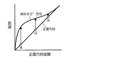
- FIG. 5 is a graph showing the relationship between the gradation characteristics in the front direction of a sub-pixel and the gradation characteristics in an oblique 60 ° direction for a three primary color liquid crystal display device that performs display in the MVA mode.
- the gray level of the red component of the multi-primary color signal input to the red sub-pixel independent driving circuit 40 4 is a graph showing a relationship between (input gradation) and a gradation level (output gradation) of a signal output from the red subpixel independent drive circuit 40;
- the gray level of the red component of the multi-primary color signal input to the red sub-pixel independent drive circuit 40 ( 4 is a graph showing a relationship between an input gradation) and a gradation level (output gradation) of a signal output from a red subpixel independent drive circuit 40.
- (A) is a graph which shows the gradation characteristic at the time of front observation, and the gradation characteristic at the time of diagonal observation about 1st red sub-pixel R1 in the case of performing independent driving
- (b) is independent driving.
- 6 is a graph showing the gradation characteristics at the time of front observation and the gradation characteristics at the time of oblique observation with respect to the second red sub-pixel R2 in the case where the above is performed. It is a graph which shows the gradation characteristic at the time of the diagonal observation in the total of 1st red sub pixel R1 and 2nd red sub pixel R2.
- (A) and (b) are graphs showing the floating of red and blue when red magenta is displayed.
- (A) corresponds to the case where independent driving is performed, and (b) performs independent driving.
- the gray level of the red component of the multi-primary color signal input to the red sub-pixel independent driving circuit 40 4 is a graph showing a relationship between a level (input gradation) and a gradation level (output gradation) of a signal output from a red subpixel independent drive circuit 40.
- 2 is a block diagram illustrating an example of a preferable configuration of a multi-primary color signal generation circuit 30.
- FIG. 1 is a figure for demonstrating the basic composition of the liquid crystal display panel of a MVA mode. These are the fragmentary sectional views which show typically the cross-sectional structure of 10 A of liquid crystal display panels of MVA mode. These are plan views schematically showing a region corresponding to one sub-pixel of the MVA mode liquid crystal display panel 10A.
- (A) And (b) is a top view which shows typically the area
- FIG. 1 shows a liquid crystal display device 100 according to this embodiment.
- the liquid crystal display device 100 includes a liquid crystal display panel 10 and a signal conversion circuit 20, and is a multi-primary color liquid crystal display device that performs color display using five primary colors.
- the liquid crystal display device 100 has a plurality of pixels arranged in a matrix. Each pixel is defined by a plurality of sub-pixels.
- FIG. 2 shows an example of a pixel configuration of the liquid crystal display device 100.
- the plurality of sub-pixels defining each pixel are the first and second red sub-pixels R1 and R2 that display red, the green sub-pixel G that displays green, and the blue sub-pixel that displays blue.
- the first red sub-pixel R1, the cyan sub-pixel C, the green sub-pixel G, the second red sub-pixel R2, the blue sub-pixel B, and the yellow sub-pixel Y are arranged from the left side in the pixel.
- the arrangement of the plurality of sub-pixels is not limited to this.
- Various arrangements disclosed in Patent Documents 2 and 3 can be employed.
- the signal conversion circuit 20 drives the input video signals corresponding to the three primary colors to the first and second red subpixels R1, R2, green subpixel G, blue subpixel B, yellow subpixel Y, and cyan subpixel C. , That is, a signal indicating the gradation level of these sub-pixels.
- the liquid crystal display panel 10 receives the signal output from the signal conversion circuit 20, and each of the plurality of sub-pixels included in each pixel lights up at a gradation level corresponding to the output signal of the signal conversion circuit 20. As a result, color display using the five primary colors is performed.
- the liquid crystal display panel 10 performs display in a vertical alignment mode (VA mode).
- VA mode vertical alignment mode
- Specific examples of the vertical alignment mode include an MVA (Multi-domain Vertical Alignment) mode disclosed in Japanese Patent Laid-Open No. 11-242225, and a CPA disclosed in Japanese Patent Laid-Open No. 2003-43525. (Continuous Pinwheel Alignment) mode can be used.
- the MVA mode or CPA mode panel includes a vertical alignment type liquid crystal layer in which liquid crystal molecules are aligned perpendicular to the substrate when no voltage is applied, and the liquid crystal molecules are aligned in a plurality of directions when voltage is applied within each sub-pixel. By tilting, a wide viewing angle display is realized.
- the first red sub-pixel R1 when a color having a hue within a predetermined range (hereinafter referred to as a “first range”) is displayed by a pixel, the first red sub-pixel R1 has a floor. The tone level and the tone level of the second red sub-pixel R2 are different from each other. That is, the first red sub-pixel R1 and the second red sub-pixel R2 are driven independently. Further, when a color having a hue within a range different from the first range (hereinafter referred to as “second range”) is displayed by the pixel, the gradation level of the first red sub-pixel R1 is The gradation level of the second red sub-pixel R2 is the same. That is, the first red sub-pixel R1 and the second red sub-pixel R2 are not driven independently.
- first range a color having a hue within a predetermined range
- the signal conversion circuit 20 in the present embodiment includes a multi-primary color signal generation circuit as shown in FIG. 30 and a red sub-pixel independent drive circuit 40.
- a multi-primary color signal generation circuit (hereinafter also simply referred to as “multi-primary color circuit”) 30 receives an input video signal corresponding to three primary colors and generates a multi-primary color signal corresponding to four or more primary colors (here, five). To do.
- the input video signal includes components indicating the gradation levels of the three primary colors. Specifically, the input video signal includes a red component Rin indicating the red gradation level, a green component Gin indicating the green gradation level, and a blue floor. A blue component Bin indicating a tone level is included.
- the multi-primary color signal includes components indicating the gradation levels of the five primary colors.
- the red component Rout indicating the red gradation level and the green component Gout indicating the green gradation level.
- a blue component Bout indicating a blue gradation level indicating a yellow component Yout indicating a yellow gradation level, and a cyan component Cout indicating a cyan gradation level.
- the red sub-pixel independent drive circuit (hereinafter also simply referred to as “independent drive circuit”) 40 is configured to output the first red sub-pixel from the red component Rout included in the multi-primary color signal according to the hue of the color indicated by the input video signal.
- the gradation level of R1 and the gradation level of the second red sub-pixel R2 are determined.
- the independent drive circuit 40 receives an input video signal (including a red component Rin, a green component Gin, and a blue component Bin) and a red component Rout of the multi-primary color signal, A signal R1out indicating the gradation level of the red sub-pixel R1 and a signal R2out indicating the gradation level of the second red sub-pixel R2 are generated and output.
- the driving method that is, the lighting pattern
- the driving method that is, the lighting pattern
- the driving method of the first red sub-pixel R1 and the second red sub-pixel R2 differs depending on the hue of the color displayed by the pixel. Yes.
- This suppresses a chromaticity shift (color shift) during oblique observation, which will be described later, thereby improving viewing angle characteristics.
- the reason why the above-described color shift occurs and the reason why the color shift is suppressed by the present invention will be described.
- the problem of viewing angle characteristics is that the ⁇ characteristics during front observation and the ⁇ characteristics during oblique observation differ. That is, a problem of viewing angle dependency of ⁇ characteristics has been pointed out.
- the ⁇ characteristic is the gradation dependence of the display luminance
- the viewing angle dependence of the ⁇ characteristic in the vertical alignment mode is visually recognized as a phenomenon in which the display luminance during oblique observation becomes higher than the original display luminance. This phenomenon is called “white float”.
- FIG. 3 shows the relationship between the gradation characteristics in the front direction of the sub-pixel and the gradation characteristics in the oblique 60 ° direction for the three primary color liquid crystal display device that performs display in the MVA mode.
- FIG. 3 is a graph for clearly expressing the difference between the gradation characteristics in the front direction and the gradation characteristics in the oblique 60 ° direction.
- the horizontal axis value is the front direction gradation
- the vertical axis value is In correspondence with the front direction and the oblique 60 ° direction, the gradation characteristic deviation is manifested as a gradation in the front direction and a gradation in the oblique 60 ° direction.
- the gradation characteristic in the oblique 60 ° direction is a curve. The amount of deviation of this curve from the straight line indicating the gradation characteristics in the front direction indicates the difference in gradation level between frontal observation and oblique observation, and this difference corresponds to the luminance deviation amount.
- FIG. 3 shows combinations of gradation levels of red subpixels, green subpixels, and blue subpixels when a pixel displays a certain color.
- the gradation levels of the red sub-pixel, the green sub-pixel, and the blue sub-pixel are higher during oblique observation than during frontal observation.
- the luminance values of the red sub-pixel, the green sub-pixel, and the blue sub-pixel are floated (increased) when viewed obliquely than when viewed from the front.
- the gradation levels of the red sub-pixel, the green sub-pixel, and the blue sub-pixel are often different from each other when displaying a certain color, as can be seen from FIG. To increase. Therefore, the luminance values of the red sub-pixel, green sub-pixel, and blue sub-pixel also increase at different ratios during oblique observation, and thus the color displayed by the pixel is shifted.
- the multi primary color liquid crystal display device there is only one combination of gradation levels of each sub-pixel for displaying a certain color.
- the multi-primary color liquid crystal display device there are many combinations of gradation levels of each sub-pixel for displaying a certain color of the pixel. This is because in a multi-primary color liquid crystal display device, it is necessary to convert an input video signal corresponding to three primary colors (that is, a three-dimensional signal) into a signal corresponding to four or more primary colors (that is, a higher-dimensional signal). This is because the conversion is highly arbitrary (freedom). Therefore, a color shift can be suppressed by selecting a combination that increases the luminance of each sub-pixel at the same ratio as much as possible during oblique observation from among a large number of combinations of gradation levels.
- the color shift in such a case is performed by making the gradation level of the first red sub-pixel R1 and the gradation level of the second red sub-pixel R2 different from each other, that is, Suppression is achieved by driving the first red sub-pixel R1 and the second red sub-pixel R2 independently.
- the gradation level (input gradation) of the red component Rout input to the independent drive circuit 40 and the gradation levels (output gradation) of the signals R1out and R2out output from the independent drive circuit 40 are shown. Shows the relationship.
- the gradation level of the red component Rout remains as it is, that is, the gradation levels of the signals R1out and R2out, that is, the first red subpixel R1 and the second red subpixel R2. It becomes a gradation level. Accordingly, the gradation levels of the first red sub-pixel R1 and the second red sub-pixel R2 are the same.
- the gradation level of the red component Rout does not directly become the gradation level of the signals R1out and R2out, but the gradation level of the first red sub-pixel R1.
- the gradation level of the second red sub-pixel R2 are different from each other.
- the input gradation increases from zero, first, only the gradation level of the second red subpixel R2 increases while the gradation level of the first red subpixel R1 remains zero.
- the gradation level of the second red sub-pixel R2 reaches the highest level (255 in this case). Thereafter, only the gradation level of the first red sub-pixel R1 increases while the gradation level of the second red sub-pixel R2 remains at the highest level.
- FIG. 6A shows the gradation characteristics at the front observation and the gradation characteristics at the oblique observation for the first red sub-pixel R1 when the independent driving is performed.
- FIG. 6B shows the gradation characteristics at the front observation and the gradation characteristics at the oblique observation for the second red sub-pixel R2 when the independent driving is performed.
- the first red sub-pixel R1 and the second red sub-pixel R2 have different gradation characteristics at the time of front observation. The gradation characteristics during observation are also different from each other.
- the gradation characteristics at the time of oblique observation of the total of the two sub-pixels displaying red are as shown in FIG.
- Each of the red sub-pixel R1 and the second red sub-pixel R2 is obtained by averaging the gradation characteristics during oblique observation.
- the gradation characteristics during oblique observation when independent driving is performed are based on the gradation characteristics during front observation compared with the gradation characteristics during oblique observation when independent driving is not performed. The amount of deviation is small. Therefore, the color shift can be suppressed by independently driving the first red sub-pixel R1 and the second red sub-pixel R2.
- the color shift can be suppressed by performing the independent driving as described above.
- FIG. 8 (a) and 8 (b) show the floating of red and blue when red magenta is displayed.
- FIG. 8A corresponds to the case where independent driving is performed
- FIG. 8B corresponds to the case where independent driving is not performed.
- the first red sub-pixel R1 and the second red sub-pixel R2 are independently driven or non-independently driven according to the hue of the color displayed by the pixel. As a result, the color shift during oblique observation is suppressed.
- drive control according to the hue will be described.
- the red subpixel independent drive circuit 40 of the liquid crystal display device 100 uses, for example, a predetermined weight function H to determine the gradation level of the first red subpixel R1 and the gradation level of the second red subpixel R2. decide.
- the weight function H is expressed by the following formula (1) when Rin>Gin> Bin, is expressed by the following formula (2) when Rin>Bin> Gin, and is expressed by the following formula ( 3).
- H (Rin ⁇ Gin) / Rin (1)
- Rin, Gin, and Bin in the above expression indicate the gradation levels indicated by the red component Rin, the green component Gin, and the blue component Bin, respectively, included in the input video signal.
- the normalized luminance indicated by the red component Rout included in the multi-primary color signal is Y (Rout), and the normalized luminance indicated by the signals R1out and R2out output from the independent drive circuit 40 (that is, the first red sub-pixel R1). And Y (R1out) and Y (R2out), respectively, as the normalized luminance of the second red sub-pixel R2.
- FIG. 9 is a diagram for conceptually explaining the weighting function H expressed by the above formulas (1) to (3).
- 9 schematically shows the hue range of the color (color displayed by the pixel) indicated by the input video signal, and W, R, G, B, Y, M, C in FIG. Respectively indicate white, red, green, blue, yellow, magenta, and cyan.
- the normalized luminance of the red component Rout of the multi-primary color signal remains as it is as the first red subpixel R1 and the second red subpixel R2. Standardized brightness. That is, the gradation level of the red component Rout of the multi-primary color signal becomes the gradation level of the first red sub-pixel R1 and the second red sub-pixel R2 as it is. Therefore, as shown in FIG. 4, the gradation level of the first red sub-pixel R1 and the gradation level of the second red sub-pixel R2 are the same, and independent driving is not performed.
- the first red The normalized luminance of the second red sub-pixel R2 is 1 when the normalized luminance of the sub-pixel R1 is a value obtained by subtracting 1 from twice the normalized luminance of the red component Rout of the multi-primary color signal. Therefore, as shown in FIG. 5, the gradation level of the first red sub-pixel R1 and the gradation level of the second red sub-pixel R2 are different from each other, and independent driving is performed.
- Independent driving is also performed when 0 ⁇ H ⁇ 1.
- H 0.5
- the gradation levels of the first red sub-pixel R1 and the second red sub-pixel R2 have a relationship as shown in FIG.
- the increase rate of the gradation level of the first red sub-pixel R1 is lower than the increase rate of the gradation level of the second red sub-pixel R2.
- the gradation level of the second red sub-pixel R2 remains the highest level thereafter. Only the gradation level of the first red sub-pixel R1 increases.
- the simulation of viewing angle characteristics was first performed when blue magenta was displayed by pixels.
- the gradation levels of the red component Rin, the green component Gin, and the blue component Bin included in the input video signal are as shown in Table 1, and the chromaticity x, y, and Y values at the time of front observation of the color displayed by the pixel Is as shown in Table 2.
- the gradation levels of the sub-pixels when the first red sub-pixel R1 and the second red sub-pixel R2 are not driven independently are as shown in Table 3, and at the time of oblique observation (in an oblique 60 ° direction)
- Table 4 shows the chromaticity x, y and Y values (when observed from the above).
- the color difference ⁇ u′v ′ calculated from the chromaticity x and y values shown in Table 2 and the chromaticity x and y values shown in Table 4 is 0.098 as shown in Table 4. .
- the gradation levels of the sub-pixels when the first red sub-pixel R1 and the second red sub-pixel R2 are driven independently are as shown in Table 5, and are at the time of oblique observation (from the oblique 60 ° direction).
- the chromaticity x, y and Y values (when observed) are as shown in Table 6.
- the color difference ⁇ u′v ′ calculated from the chromaticity x and y values shown in Table 2 and the chromaticity x and y values shown in Table 6 is 0.079 as shown in Table 6. .
- the color difference ⁇ u′v ′ between the front observation and the oblique observation becomes small, and the color shift is suppressed. It was confirmed.
- a viewing angle characteristic was simulated when red magenta was displayed by the pixel.
- the gradation levels of the red component Rin, the green component Gin, and the blue component Bin included in the input video signal are as shown in Table 7, and the chromaticity x, y, and Y values during frontal observation of the color displayed by the pixel Is as shown in Table 8.
- the gradation levels of the sub-pixels when the first red sub-pixel R1 and the second red sub-pixel R2 are not driven independently are as shown in Table 9, and during oblique observation (in an oblique 60 ° direction)
- Table 10 shows the chromaticity x, y, and Y values (when observed from the above).
- the color difference ⁇ u′v ′ calculated from the chromaticity x and y values shown in Table 8 and the chromaticity x and y values shown in Table 10 is 0.053 as shown in Table 10. .
- the gradation levels of the sub-pixels when the first red sub-pixel R1 and the second red sub-pixel R2 are driven independently are as shown in Table 11, and are at the time of oblique observation (from the oblique 60 ° direction).
- the chromaticity x, y and Y values (when observed) are as shown in Table 12.
- the color difference ⁇ u′v ′ calculated from the chromaticity x and y values shown in Table 8 and the chromaticity x and y values shown in Table 12 is 0.080 as shown in Table 12. .
- the first red sub-pixel R1 and the second red sub-pixel R2 are not independently driven, so that the front observation and the oblique observation are performed more than the independent driving. It was confirmed that the color difference ⁇ u′v ′ was reduced and the color shift was suppressed.
- one pixel is defined by six sub-pixels and a color display is performed using five primary colors.
- the present invention is not limited to this. Further, one pixel is defined by more (seven or more) sub-pixels and a color display is performed using six or more primary colors, or one pixel is defined by five sub-pixels and four primary colors are used. Alternatively, a configuration for performing color display may be employed.
- one pixel is defined by the first red sub-pixel R1, the second red sub-pixel R2, the green sub-pixel G, the blue sub-pixel B, and the cyan sub-pixel C.
- it may be defined by the first red subpixel R1, the second red subpixel R2, the green subpixel G, the blue subpixel B, and the yellow subpixel Y.
- the effect of improving the viewing angle characteristics according to the present invention is that the former configuration (when the pixel does not include the yellow subpixel Y and the cyan subpixel C) includes the latter configuration (the pixel includes the cyan subpixel C). Is higher than when yellow sub-pixel Y is included).
- the color close to yellow is basically displayed by combining red and green (that is, the number of primary colors used for color mixture is small), so selectable gradations Although the combination of levels is small, the effect of suppressing color shift is obtained for colors close to magenta, and for the colors close to yellow, the first red sub-pixel R1 and the second red sub-pixel are also selected according to the hue. This is because a color shift suppression effect can be obtained by driving the pixel R2 independently or non-independently.
- FIG. 11 shows an example of a specific configuration of the multi-primary color signal generation circuit 30 included in the signal conversion circuit 20 of the liquid crystal display device 100.
- a multi-primary color signal generation circuit 30 shown in FIG. 11 includes a conversion matrix 31, a mapping unit 32, a plurality of two-dimensional lookup tables 33, and a multiplier 34.
- the video signal (Rin, Gin, Bin) input from the outside is converted into a signal (XYZ signal) corresponding to the color space of the XYZ color system by the conversion matrix 31.
- the XYZ signal is mapped to the xy coordinate space by the mapping unit 32, thereby generating a signal corresponding to the Y value and the chromaticity coordinates (x, y).
- data (r, g, b, ye, etc.) corresponding to the hue and saturation of the primary colors used for color mixing are obtained from the chromaticity coordinates (x, y). c) is generated.
- signals Rout, Gout, Bout, Yout, and Cout corresponding to the respective primary colors are generated. Note that the method described here is an example, and the method of generating the multi-primary color signal is not limited to this.
- the components included in the signal conversion circuit 20 can be realized by hardware, and some or all of them can be realized by software.
- these components may be configured using a computer.
- This computer includes a CPU (central processing unit) for executing various programs and a work area for executing these programs.
- RAM random access memory
- achieving the function of each component is run in a computer, and this computer is operated as each component.
- Each subpixel of the liquid crystal display panels 10A, 10B, and 10C includes a first electrode 1, a second electrode 2 that faces the first electrode 1, and a vertical alignment provided between the first electrode 1 and the second electrode 2.
- Type liquid crystal layer 3. The vertical alignment type liquid crystal layer 3 aligns liquid crystal molecules 3a having a negative dielectric anisotropy substantially perpendicular to the surfaces of the first electrode 1 and the second electrode 2 (for example, 87 ° or more and 90 ° or less) when no voltage is applied. It is a thing. Typically, it is obtained by providing a vertical alignment film (not shown) on the surface of each of the first electrode 1 and the second electrode 2 on the liquid crystal layer 3 side.
- First alignment regulating means (4, 5, 6) is provided on the first electrode 1 side of the liquid crystal layer 3, and second alignment regulating means (7, 8,. 9) is provided.
- the liquid crystal molecules 3a receive the alignment regulating force from the first alignment regulating means and the second alignment regulating means, and receive the first electrode.
- a voltage is applied between the first electrode 2 and the second electrode 2, it falls down (inclined) in the direction indicated by the arrow in the figure. That is, since the liquid crystal molecules 3a are tilted in a uniform direction in each liquid crystal region, each liquid crystal region can be regarded as a domain.
- the first alignment regulating means and the second alignment regulating means are provided in a strip shape within each sub-pixel, and are shown in FIGS. (C) is sectional drawing in the direction orthogonal to the extending direction of a strip
- orientation regulating means various orientation regulating means (domain regulating means) as disclosed in JP-A-11-242225 can be used.
- a liquid crystal display panel 10A shown in FIG. 12A has ribs (projections) 4 as first alignment regulating means, and slits (parts where no conductive film exists) provided in the second electrode 2 as second alignment regulating means. ) 7.
- ribs 4 and the slits 7 extends in a strip shape (strip shape).
- the ribs 4 orient the liquid crystal molecules 3 a substantially perpendicular to the side surfaces 4 a, thereby acting to align the liquid crystal molecules 3 a in a direction perpendicular to the extending direction of the ribs 4.
- the slit 7 generates an oblique electric field in the liquid crystal layer 3 near the edge of the slit 7 when a potential difference is formed between the first electrode 1 and the second electrode 2, and is orthogonal to the extending direction of the slit 7. It acts to align the liquid crystal molecules 3a in the direction in which they are directed.
- the ribs 4 and the slits 7 are arranged in parallel to each other with a certain distance therebetween, and a liquid crystal region (domain) is formed between the ribs 4 and the slits 7 adjacent to each other.
- the liquid crystal display panel 10B shown in FIG. 12B has a rib (first rib) 5 and a rib (second rib) 8 as the first alignment regulating means and the second alignment regulating means, respectively.
- the ribs 5 and the ribs 8 are arranged in parallel with each other at a predetermined interval, and by acting to align the liquid crystal molecules 3a substantially vertically on the side surface 5a of the rib 5 and the side surface 8a of the rib 8, A liquid crystal region (domain) is formed between them.
- the liquid crystal display panel 10C shown in FIG. 12C has a slit (first slit) 6 and a slit (second slit) 9 as the first alignment regulating means and the second alignment regulating means, respectively.
- first slit first slit
- second slit second slit
- the slit 6 and the slit 9 generate an oblique electric field in the liquid crystal layer 3 in the vicinity of the end sides of the slits 6 and 9.
- the liquid crystal molecules 3a are aligned in a direction perpendicular to the extending direction of 9 and 9.
- the slit 6 and the slit 9 are arranged in parallel to each other with a certain interval, and a liquid crystal region (domain) is formed between them.
- first electrode 1 and the second electrode 2 may be electrodes that face each other with the liquid crystal layer 3 interposed therebetween.
- one is a counter electrode and the other is a pixel electrode.
- a rib 4 is provided as the first alignment regulating means, and the slit provided in the pixel electrode as the second alignment regulating means.
- FIG. 13 is a partial cross-sectional view schematically showing a cross-sectional structure of the liquid crystal display panel 10A
- FIG. 14 is a plan view schematically showing a region corresponding to one subpixel of the liquid crystal display panel 10A.
- the liquid crystal display panel 10A is provided between a first substrate (for example, a glass substrate) 10a, a second substrate (for example, a glass substrate) 10b facing the first substrate 10a, and the first substrate 10a and the second substrate 10b.
- the vertical alignment type liquid crystal layer 3 is provided.
- the counter electrode 1 is provided on the liquid crystal layer 3 side of the first substrate 10a, and a rib 4 is further formed thereon.
- a vertical alignment film (not shown) is provided on almost the entire surface of the counter electrode 1 including the rib 4 on the liquid crystal layer 3 side surface. As shown in FIG. 14, the ribs 4 extend in a band shape, and the adjacent ribs 4 are arranged in parallel to each other.
- gate bus lines scanning lines
- source bus lines signal lines
- TFTs not shown
- An interlayer insulating film 12 is formed.
- a pixel electrode 2 is formed on the interlayer insulating film 12. The pixel electrode 2 and the counter electrode 1 are opposed to each other through the liquid crystal layer 3.
- a strip-shaped slit 7 is formed in the pixel electrode 2, and a vertical alignment film (not shown) is formed on almost the entire surface of the pixel electrode 2 including the slit 7. As shown in FIG. 14, the slit 7 extends in a band shape. The two adjacent slits 7 are arranged in parallel to each other, and are arranged so that the interval between the adjacent ribs 4 is approximately divided into two.
- the orientation direction is regulated by the ribs 4 and the slits 7 on both sides thereof, and liquid crystal molecules are arranged on both sides of the ribs 4 and the slits 7 respectively. Domains in which the directions in which 3a falls are different from each other by 180 ° are formed.
- the ribs 4 and the slits 7 extend along two directions different from each other by 90 °, and the orientation direction of the liquid crystal molecules 3a is 90 ° in each sub-pixel. Four different types of domains are formed.
- a pair of polarizing plates (not shown) arranged on both sides of the first substrate 10a and the second substrate 10b are arranged so that the transmission axes are substantially orthogonal to each other (crossed Nicols state).
- the orientation directions and the transmission axis of the polarizing plate are 45 °, the change in retardation due to the formation of the domains is most efficient. Can be used. Therefore, it is preferable to arrange the polarizing plate so that the transmission axis forms approximately 45 ° with the extending direction of the rib 4 and the slit 7.
- a display device that often moves the observation direction horizontally with respect to the display surface, such as a television, it is possible to arrange one transmission axis of the pair of polarizing plates in the horizontal direction with respect to the display surface, This is preferable in order to suppress the viewing angle dependency of display quality.
- the liquid crystal display panel 10A having the above-described configuration, when a predetermined voltage is applied to the liquid crystal layer 3 in each sub-pixel, a plurality of regions (domains) having different orientations in which the liquid crystal molecules 3a are inclined are formed. A wide viewing angle display is realized. However, even in such a liquid crystal display panel 10A, color shift due to whitening may occur during oblique observation. As in the liquid crystal display device 100 in the present embodiment, the first red sub-pixel R1 and the second red sub-pixel R2 are independently driven or non-independently driven according to the hue of the color displayed by the pixel. It is possible to perform a high-quality display in which a chromaticity shift due to white floating is hardly visible.
- the pixel electrode 2 of the liquid crystal display panel 10D shown in FIG. 15A has a plurality of notches 2b formed at predetermined positions, and is divided into a plurality of sub-pixel electrodes 2a by these notches 2b. ing.
- Each of the plurality of sub-pixel electrodes 2a has a substantially rectangular shape.
- a case where the pixel electrode 2 is divided into three sub-pixel electrodes 2a is illustrated, but the number of divisions is not limited to this.
- the first red sub-pixel R1 and the second red sub-pixel R2 are independently driven or non-independently driven according to the hue of the color displayed by the pixel. It is possible to perform a high-quality display in which a chromaticity shift due to white floating is hardly visible.
- FIG. 15 illustrates the pixel electrode 2 in which the notch 2b is formed, as shown in FIG. 16, an opening 2c may be formed instead of the notch 2b.
- the pixel electrode 2 shown in FIG. 16 has a plurality of openings 2c and is divided into a plurality of sub-pixel electrodes 2a by these openings 2c.
- the axially symmetrical orientation (radially inclined orientation) is generated by the oblique electric field generated in the vicinity of the outer edge of the pixel electrode 2 and in the opening 2c. ) Are formed.
- 15 and 16 illustrate the configuration in which one pixel electrode 2 is provided with a plurality of notches 2b or openings 2c.
- the notches Only one 2b or one opening 2c may be provided. That is, by providing at least one notch 2b or opening 2c in the pixel electrode 2, a plurality of axially symmetric liquid crystal domains can be formed.
- the shape of the pixel electrode 2 various shapes as disclosed in, for example, Japanese Patent Application Laid-Open No. 2003-43525 can be used.
- the present invention it is possible to improve the viewing angle characteristics of a multi-primary color liquid crystal display device in which a plurality of red sub-pixels are provided in one pixel.
- the multi-primary color liquid crystal display device according to the present invention suppresses a color shift caused by white floating when observed from an oblique direction, so that high-quality display can be performed. It is suitably used for electronic equipment.
Abstract
Priority Applications (3)
| Application Number | Priority Date | Filing Date | Title |
|---|---|---|---|
| US13/131,289 US9324286B2 (en) | 2008-11-28 | 2009-11-24 | Multiple primary color liquid crystal display device and signal conversion circuit |
| JP2010540361A JPWO2010061577A1 (ja) | 2008-11-28 | 2009-11-24 | 多原色液晶表示装置および信号変換回路 |
| CN200980147807.5A CN102227675B (zh) | 2008-11-28 | 2009-11-24 | 多原色液晶显示装置和信号转换电路 |
Applications Claiming Priority (2)
| Application Number | Priority Date | Filing Date | Title |
|---|---|---|---|
| JP2008305547 | 2008-11-28 | ||
| JP2008-305547 | 2008-11-28 |
Publications (1)
| Publication Number | Publication Date |
|---|---|
| WO2010061577A1 true WO2010061577A1 (fr) | 2010-06-03 |
Family
ID=42225464
Family Applications (1)
| Application Number | Title | Priority Date | Filing Date |
|---|---|---|---|
| PCT/JP2009/006319 WO2010061577A1 (fr) | 2008-11-28 | 2009-11-24 | Dispositif d’affichage à cristaux liquides à couleurs primaires multiples et circuit de conversion de signaux |
Country Status (4)
| Country | Link |
|---|---|
| US (1) | US9324286B2 (fr) |
| JP (1) | JPWO2010061577A1 (fr) |
| CN (1) | CN102227675B (fr) |
| WO (1) | WO2010061577A1 (fr) |
Cited By (2)
| Publication number | Priority date | Publication date | Assignee | Title |
|---|---|---|---|---|
| WO2012067038A1 (fr) * | 2010-11-15 | 2012-05-24 | シャープ株式会社 | Dispositif d'affichage à couleurs multi-primaires |
| WO2013031770A1 (fr) * | 2011-08-31 | 2013-03-07 | シャープ株式会社 | Dispositif d'affichage à cristaux liquides |
Families Citing this family (29)
| Publication number | Priority date | Publication date | Assignee | Title |
|---|---|---|---|---|
| JP5808171B2 (ja) * | 2010-07-16 | 2015-11-10 | 株式会社 資生堂 | 目元画像シミュレーション装置、目元画像生成方法、及び目元画像生成プログラム |
| WO2012090880A1 (fr) * | 2010-12-28 | 2012-07-05 | シャープ株式会社 | Circuit de conversion de signaux et dispositif d'affichage à cristaux liquides à multiples couleurs primaires comprenant ledit circuit |
| JP6654280B2 (ja) * | 2015-01-14 | 2020-02-26 | 天馬微電子有限公司 | 画素アレイ及び電気光学装置並びに電気機器並びに画素アレイの駆動方法 |
| CN107945729B (zh) | 2017-12-15 | 2020-05-08 | 京东方科技集团股份有限公司 | 转换方法及电路、显示装置及驱动方法和电路、存储介质 |
| US10665141B2 (en) | 2018-09-28 | 2020-05-26 | Apple Inc. | Super-resolution, extended-range rendering for enhanced subpixel geometry |
| US11030934B2 (en) | 2018-10-25 | 2021-06-08 | Baylor University | System and method for a multi-primary wide gamut color system |
| US11532261B1 (en) | 2018-10-25 | 2022-12-20 | Baylor University | System and method for a multi-primary wide gamut color system |
| US11289003B2 (en) | 2018-10-25 | 2022-03-29 | Baylor University | System and method for a multi-primary wide gamut color system |
| US10997896B2 (en) | 2018-10-25 | 2021-05-04 | Baylor University | System and method for a six-primary wide gamut color system |
| US11587491B1 (en) | 2018-10-25 | 2023-02-21 | Baylor University | System and method for a multi-primary wide gamut color system |
| US11037481B1 (en) | 2018-10-25 | 2021-06-15 | Baylor University | System and method for a multi-primary wide gamut color system |
| US11043157B2 (en) | 2018-10-25 | 2021-06-22 | Baylor University | System and method for a six-primary wide gamut color system |
| US11062638B2 (en) | 2018-10-25 | 2021-07-13 | Baylor University | System and method for a multi-primary wide gamut color system |
| US11289000B2 (en) | 2018-10-25 | 2022-03-29 | Baylor University | System and method for a multi-primary wide gamut color system |
| US10607527B1 (en) | 2018-10-25 | 2020-03-31 | Baylor University | System and method for a six-primary wide gamut color system |
| US10950162B2 (en) | 2018-10-25 | 2021-03-16 | Baylor University | System and method for a six-primary wide gamut color system |
| US11341890B2 (en) | 2018-10-25 | 2022-05-24 | Baylor University | System and method for a multi-primary wide gamut color system |
| US11403987B2 (en) | 2018-10-25 | 2022-08-02 | Baylor University | System and method for a multi-primary wide gamut color system |
| US11189210B2 (en) | 2018-10-25 | 2021-11-30 | Baylor University | System and method for a multi-primary wide gamut color system |
| US11410593B2 (en) | 2018-10-25 | 2022-08-09 | Baylor University | System and method for a multi-primary wide gamut color system |
| US11069280B2 (en) | 2018-10-25 | 2021-07-20 | Baylor University | System and method for a multi-primary wide gamut color system |
| US11315467B1 (en) | 2018-10-25 | 2022-04-26 | Baylor University | System and method for a multi-primary wide gamut color system |
| US11488510B2 (en) | 2018-10-25 | 2022-11-01 | Baylor University | System and method for a multi-primary wide gamut color system |
| US11373575B2 (en) | 2018-10-25 | 2022-06-28 | Baylor University | System and method for a multi-primary wide gamut color system |
| US11069279B2 (en) | 2018-10-25 | 2021-07-20 | Baylor University | System and method for a multi-primary wide gamut color system |
| US11475819B2 (en) | 2018-10-25 | 2022-10-18 | Baylor University | System and method for a multi-primary wide gamut color system |
| US10950161B2 (en) | 2018-10-25 | 2021-03-16 | Baylor University | System and method for a six-primary wide gamut color system |
| CN113795879B (zh) * | 2019-04-17 | 2023-04-07 | 深圳云英谷科技有限公司 | 用于确定显示面板中灰度映射相关性的方法及系统 |
| CN110136631B (zh) * | 2019-06-25 | 2022-03-01 | 惠州市华星光电技术有限公司 | 显示装置显示画面的调整方法 |
Citations (1)
| Publication number | Priority date | Publication date | Assignee | Title |
|---|---|---|---|---|
| WO2008090845A1 (fr) * | 2007-01-25 | 2008-07-31 | Sharp Kabushiki Kaisha | Dispositif d'affichage en multi-couleurs primaires |
Family Cites Families (17)
| Publication number | Priority date | Publication date | Assignee | Title |
|---|---|---|---|---|
| US4800375A (en) * | 1986-10-24 | 1989-01-24 | Honeywell Inc. | Four color repetitive sequence matrix array for flat panel displays |
| JP3362758B2 (ja) | 1996-03-15 | 2003-01-07 | 富士ゼロックス株式会社 | 反射型カラー表示装置 |
| EP1621923B8 (fr) * | 1997-06-12 | 2010-03-24 | Sharp Kabushiki Kaisha | Dispositif d'affichage à cristal liquide d'orientation verticale |
| JP4034022B2 (ja) | 2000-01-25 | 2008-01-16 | シャープ株式会社 | 液晶表示装置 |
| JP2001306023A (ja) | 2000-04-18 | 2001-11-02 | Seiko Epson Corp | 画像表示装置 |
| JP3601786B2 (ja) * | 2000-08-11 | 2004-12-15 | シャープ株式会社 | 液晶表示装置 |
| EP2273481A3 (fr) * | 2001-06-11 | 2012-02-22 | Genoa Color Technologies Ltd. | Dispositif, système et procédé d'affichage en couleur |
| US7583279B2 (en) * | 2004-04-09 | 2009-09-01 | Samsung Electronics Co., Ltd. | Subpixel layouts and arrangements for high brightness displays |
| US9953590B2 (en) * | 2002-04-11 | 2018-04-24 | Samsung Display Co., Ltd. | Color display devices and methods with enhanced attributes |
| US7495722B2 (en) * | 2003-12-15 | 2009-02-24 | Genoa Color Technologies Ltd. | Multi-color liquid crystal display |
| JP4549881B2 (ja) * | 2004-03-18 | 2010-09-22 | シャープ株式会社 | 色信号変換装置、表示ユニット、色信号変換プログラム、色信号変換プログラムを記録したコンピュータ読み取り可能な記録媒体 |
| JP4371097B2 (ja) * | 2005-09-20 | 2009-11-25 | エプソンイメージングデバイス株式会社 | 照明装置、電気光学装置及び電子機器 |
| CN102122460B (zh) * | 2005-09-21 | 2012-08-29 | 夏普株式会社 | 显示装置和滤色基片 |
| KR101206724B1 (ko) * | 2006-02-23 | 2012-11-30 | 삼성디스플레이 주식회사 | 표시 장치 |
| WO2008047725A1 (fr) * | 2006-10-13 | 2008-04-24 | Sharp Kabushiki Kaisha | Dispositif d'affichage et dispositif de conversion de signaux |
| EP2128844A4 (fr) * | 2007-03-16 | 2011-08-10 | Sharp Kk | Dispositif d'affichage |
| EP2223294B1 (fr) * | 2007-11-20 | 2013-04-10 | Semiconductor Energy Laboratory Co, Ltd. | Dispositif d'affichage à cristaux liquides et procédé d'affichage d'image de celui-ci |
-
2009
- 2009-11-24 WO PCT/JP2009/006319 patent/WO2010061577A1/fr active Application Filing
- 2009-11-24 CN CN200980147807.5A patent/CN102227675B/zh not_active Expired - Fee Related
- 2009-11-24 JP JP2010540361A patent/JPWO2010061577A1/ja active Pending
- 2009-11-24 US US13/131,289 patent/US9324286B2/en not_active Expired - Fee Related
Patent Citations (1)
| Publication number | Priority date | Publication date | Assignee | Title |
|---|---|---|---|---|
| WO2008090845A1 (fr) * | 2007-01-25 | 2008-07-31 | Sharp Kabushiki Kaisha | Dispositif d'affichage en multi-couleurs primaires |
Cited By (2)
| Publication number | Priority date | Publication date | Assignee | Title |
|---|---|---|---|---|
| WO2012067038A1 (fr) * | 2010-11-15 | 2012-05-24 | シャープ株式会社 | Dispositif d'affichage à couleurs multi-primaires |
| WO2013031770A1 (fr) * | 2011-08-31 | 2013-03-07 | シャープ株式会社 | Dispositif d'affichage à cristaux liquides |
Also Published As
| Publication number | Publication date |
|---|---|
| US20110227965A1 (en) | 2011-09-22 |
| US9324286B2 (en) | 2016-04-26 |
| CN102227675B (zh) | 2014-05-28 |
| JPWO2010061577A1 (ja) | 2012-04-26 |
| CN102227675A (zh) | 2011-10-26 |
Similar Documents
| Publication | Publication Date | Title |
|---|---|---|
| WO2010061577A1 (fr) | Dispositif d’affichage à cristaux liquides à couleurs primaires multiples et circuit de conversion de signaux | |
| JP5244174B2 (ja) | 信号変換回路およびそれを備えた多原色液晶表示装置 | |
| JP5680969B2 (ja) | 液晶表示装置 | |
| JP5080658B2 (ja) | 液晶表示装置 | |
| JP5395092B2 (ja) | 表示装置 | |
| US7911541B2 (en) | Liquid crystal display device | |
| US20200090604A1 (en) | Image processing method, image processing device and display device | |
| JP5426559B2 (ja) | 多原色液晶表示装置 | |
| JP6140711B2 (ja) | 液晶表示装置 | |
| JP5043860B2 (ja) | 信号変換回路およびそれを備えた多原色液晶表示装置 | |
| US9058783B2 (en) | Liquid-crystal display device | |
| WO2011010637A1 (fr) | Procédé de fabrication d'un dispositif d'affichage à cristaux liquides | |
| WO2012005170A1 (fr) | Appareil d'affichage à cristaux liquides présentant plusieurs couleurs primaires | |
| JP2012027397A (ja) | 液晶表示装置 | |
| WO2012090823A1 (fr) | Dispositif d'affichage à cristaux liquides | |
| WO2012090880A1 (fr) | Circuit de conversion de signaux et dispositif d'affichage à cristaux liquides à multiples couleurs primaires comprenant ledit circuit | |
| JP5485366B2 (ja) | 表示装置 | |
| JPH07120724A (ja) | 液晶ディスプレイ装置の中間調表示方法 | |
| JP2014048583A (ja) | 多原色液晶表示装置 |
Legal Events
| Date | Code | Title | Description |
|---|---|---|---|
| WWE | Wipo information: entry into national phase |
Ref document number: 200980147807.5 Country of ref document: CN |
|
| 121 | Ep: the epo has been informed by wipo that ep was designated in this application |
Ref document number: 09828827 Country of ref document: EP Kind code of ref document: A1 |
|
| ENP | Entry into the national phase |
Ref document number: 2010540361 Country of ref document: JP Kind code of ref document: A |
|
| WWE | Wipo information: entry into national phase |
Ref document number: 13131289 Country of ref document: US |
|
| NENP | Non-entry into the national phase |
Ref country code: DE |
|
| 122 | Ep: pct application non-entry in european phase |
Ref document number: 09828827 Country of ref document: EP Kind code of ref document: A1 |