WO2010058546A1 - 立体視再生を行う再生装置、再生方法、プログラム - Google Patents
立体視再生を行う再生装置、再生方法、プログラム Download PDFInfo
- Publication number
- WO2010058546A1 WO2010058546A1 PCT/JP2009/006115 JP2009006115W WO2010058546A1 WO 2010058546 A1 WO2010058546 A1 WO 2010058546A1 JP 2009006115 W JP2009006115 W JP 2009006115W WO 2010058546 A1 WO2010058546 A1 WO 2010058546A1
- Authority
- WO
- WIPO (PCT)
- Prior art keywords
- plane
- video
- offset
- image
- data
- Prior art date
Links
- 238000000034 method Methods 0.000 title claims description 164
- 238000003860 storage Methods 0.000 claims description 179
- 238000012545 processing Methods 0.000 claims description 126
- 230000015654 memory Effects 0.000 claims description 94
- 238000004364 calculation method Methods 0.000 claims description 51
- 230000015572 biosynthetic process Effects 0.000 claims description 34
- 238000003786 synthesis reaction Methods 0.000 claims description 33
- 230000033001 locomotion Effects 0.000 claims description 24
- 230000002194 synthesizing effect Effects 0.000 claims description 4
- 238000013507 mapping Methods 0.000 claims 2
- 230000008859 change Effects 0.000 abstract description 17
- 230000002452 interceptive effect Effects 0.000 description 219
- 230000008569 process Effects 0.000 description 90
- 238000010586 diagram Methods 0.000 description 40
- 230000006870 function Effects 0.000 description 32
- 230000000694 effects Effects 0.000 description 31
- 238000007726 management method Methods 0.000 description 28
- 239000004973 liquid crystal related substance Substances 0.000 description 27
- 239000011521 glass Substances 0.000 description 26
- 230000009467 reduction Effects 0.000 description 22
- 239000004065 semiconductor Substances 0.000 description 20
- 239000002131 composite material Substances 0.000 description 19
- 239000000203 mixture Substances 0.000 description 19
- 238000009877 rendering Methods 0.000 description 16
- 239000000872 buffer Substances 0.000 description 15
- 230000003287 optical effect Effects 0.000 description 14
- 208000003464 asthenopia Diseases 0.000 description 10
- 230000005540 biological transmission Effects 0.000 description 8
- 238000001514 detection method Methods 0.000 description 8
- 230000001360 synchronised effect Effects 0.000 description 8
- 238000005516 engineering process Methods 0.000 description 7
- 230000003068 static effect Effects 0.000 description 7
- 230000007246 mechanism Effects 0.000 description 6
- 230000004044 response Effects 0.000 description 6
- 238000004458 analytical method Methods 0.000 description 5
- 238000013461 design Methods 0.000 description 5
- 230000001172 regenerating effect Effects 0.000 description 5
- 238000004422 calculation algorithm Methods 0.000 description 4
- 238000006243 chemical reaction Methods 0.000 description 4
- 238000012546 transfer Methods 0.000 description 4
- 230000011664 signaling Effects 0.000 description 3
- 230000000007 visual effect Effects 0.000 description 3
- 239000003855 balanced salt solution Substances 0.000 description 2
- 238000006073 displacement reaction Methods 0.000 description 2
- 229940053083 eye stream Drugs 0.000 description 2
- 238000001914 filtration Methods 0.000 description 2
- 238000005206 flow analysis Methods 0.000 description 2
- 230000006872 improvement Effects 0.000 description 2
- 238000012423 maintenance Methods 0.000 description 2
- 238000005457 optimization Methods 0.000 description 2
- 230000002093 peripheral effect Effects 0.000 description 2
- 238000013468 resource allocation Methods 0.000 description 2
- 238000000926 separation method Methods 0.000 description 2
- 239000000758 substrate Substances 0.000 description 2
- 230000002123 temporal effect Effects 0.000 description 2
- 230000001960 triggered effect Effects 0.000 description 2
- 206010053615 Thermal burn Diseases 0.000 description 1
- 230000004913 activation Effects 0.000 description 1
- 239000008186 active pharmaceutical agent Substances 0.000 description 1
- 230000001174 ascending effect Effects 0.000 description 1
- 230000006399 behavior Effects 0.000 description 1
- 230000033228 biological regulation Effects 0.000 description 1
- 239000003086 colorant Substances 0.000 description 1
- 238000004891 communication Methods 0.000 description 1
- 238000012790 confirmation Methods 0.000 description 1
- 238000005520 cutting process Methods 0.000 description 1
- 238000011161 development Methods 0.000 description 1
- 230000018109 developmental process Effects 0.000 description 1
- 230000007717 exclusion Effects 0.000 description 1
- 210000003128 head Anatomy 0.000 description 1
- 238000003780 insertion Methods 0.000 description 1
- 230000037431 insertion Effects 0.000 description 1
- 230000010354 integration Effects 0.000 description 1
- NUHSROFQTUXZQQ-UHFFFAOYSA-N isopentenyl diphosphate Chemical compound CC(=C)CCO[P@](O)(=O)OP(O)(O)=O NUHSROFQTUXZQQ-UHFFFAOYSA-N 0.000 description 1
- 238000004519 manufacturing process Methods 0.000 description 1
- 230000008447 perception Effects 0.000 description 1
- 230000036316 preload Effects 0.000 description 1
- 238000003825 pressing Methods 0.000 description 1
- 238000011946 reduction process Methods 0.000 description 1
- 238000011069 regeneration method Methods 0.000 description 1
- 239000011347 resin Substances 0.000 description 1
- 229920005989 resin Polymers 0.000 description 1
- 238000013519 translation Methods 0.000 description 1
- 238000002834 transmittance Methods 0.000 description 1
- 238000012795 verification Methods 0.000 description 1
Images


Classifications
-
- H—ELECTRICITY
- H04—ELECTRIC COMMUNICATION TECHNIQUE
- H04N—PICTORIAL COMMUNICATION, e.g. TELEVISION
- H04N13/00—Stereoscopic video systems; Multi-view video systems; Details thereof
- H04N13/10—Processing, recording or transmission of stereoscopic or multi-view image signals
- H04N13/106—Processing image signals
- H04N13/139—Format conversion, e.g. of frame-rate or size
-
- H—ELECTRICITY
- H04—ELECTRIC COMMUNICATION TECHNIQUE
- H04N—PICTORIAL COMMUNICATION, e.g. TELEVISION
- H04N13/00—Stereoscopic video systems; Multi-view video systems; Details thereof
- H04N13/10—Processing, recording or transmission of stereoscopic or multi-view image signals
- H04N13/106—Processing image signals
- H04N13/128—Adjusting depth or disparity
-
- H—ELECTRICITY
- H04—ELECTRIC COMMUNICATION TECHNIQUE
- H04N—PICTORIAL COMMUNICATION, e.g. TELEVISION
- H04N13/00—Stereoscopic video systems; Multi-view video systems; Details thereof
- H04N13/10—Processing, recording or transmission of stereoscopic or multi-view image signals
- H04N13/106—Processing image signals
- H04N13/156—Mixing image signals
-
- H—ELECTRICITY
- H04—ELECTRIC COMMUNICATION TECHNIQUE
- H04N—PICTORIAL COMMUNICATION, e.g. TELEVISION
- H04N13/00—Stereoscopic video systems; Multi-view video systems; Details thereof
- H04N13/10—Processing, recording or transmission of stereoscopic or multi-view image signals
- H04N13/106—Processing image signals
- H04N13/161—Encoding, multiplexing or demultiplexing different image signal components
-
- H—ELECTRICITY
- H04—ELECTRIC COMMUNICATION TECHNIQUE
- H04N—PICTORIAL COMMUNICATION, e.g. TELEVISION
- H04N13/00—Stereoscopic video systems; Multi-view video systems; Details thereof
- H04N13/10—Processing, recording or transmission of stereoscopic or multi-view image signals
- H04N13/106—Processing image signals
- H04N13/172—Processing image signals image signals comprising non-image signal components, e.g. headers or format information
- H04N13/183—On-screen display [OSD] information, e.g. subtitles or menus
Definitions
- the present invention belongs to the technical field of stereoscopic reproduction.
- Stereoscopic playback technology refers to a technology that artificially creates a stereoscopic image by introducing a mechanism to show different pictures for the left and right eyes and using the parallax between the eyes.
- stereoscopic displays for allowing the user to view stereoscopic images.
- one of the commonly used methods is a method using shutter glasses.
- the viewer's left eye and right eye fields of view are alternately covered with glasses at high speed, and the display image on the display is updated at high speed for the left and right eyes in synchronization with the operation of the glasses.
- the left-eye image displayed on the display as a result can be seen only by the shutter glasses, while the right-eye image can be seen only by the right eye.
- the first method is a method in which video streams for left eye and right eye are prepared, corresponding left eye subtitles and right eye subtitles are prepared separately, and each is superimposed and displayed.
- the second method is a method of bringing a stereoscopic effect to a video from one video stream and corresponding depth information, and superimposing a caption object thereon, as in Patent Document 2.
- the depth of the portion where the subtitle overlaps with the video is displayed as zero parallax, that is, the depth is eliminated, so that the user does not feel the difference in depth between the subtitle and the video.
- the third method is a method in which one caption object is prepared for the left-eye video stream and the right-eye video stream prepared in advance, and a stereoscopic effect with a plane shift is superimposed from the depth information.
- the second method eliminates the need to create left and right graphics streams for subtitle display, and can reduce the burden of authoring, but it loses a sense of depth when the subtitles overlap the stream. So it doesn't look good.
- the plane shift method it is not necessary to create both left and right graphics streams for subtitles / GUI, and there is no loss of depth in the part where subtitles / GUI overlaps with moving images. Will be the most ideal. However, the plane shift has a negative effect when a scaling function for enlarging or reducing the displayed screen is executed.
- the character is reduced by scaling, but the character position remains the same as before the scaling, and the depth of the subtitle character is maintained.
- the depth of the video is reduced, but the subtitles remain as they are, and the difference between the three-dimensionality of the video and the subtitles / GUI becomes severe during scaling.
- the above-described problems do not occur if scaling is prohibited in a state in which captions are synthesized.
- the current playback device displays a full-screen menu and displays a reduced scaled video on it when a menu call operation is performed during playback of a full-screen moving image. To do. This is because such processing makes it possible to widen the field of view of the menu without disturbing the viewing of the video.
- GUI processing with video scaling broadens the menu field of view and preserves user convenience, so omitting GUI processing with scaling scaling, even for stereoscopic viewing, This means retreating from the convenience of the current optical disk playback device, and is never a useful idea for the industry.
- An object of the present invention is to provide a playback device capable of reducing the sense of reality and observing consumer protection while realizing GUI processing with video scaling.
- a playback apparatus is a playback apparatus that realizes stereoscopic playback,
- a video decoder for decoding a video stream to obtain a video frame, a plane memory for storing graphics data composed of a plurality of pixel data having a predetermined number of vertical pixels ⁇ horizontal number of pixels,
- an offset holding unit that holds an offset indicating a reference of how much the pixel coordinates should be moved in each of the right direction and the left direction
- a shift engine that moves the respective coordinates of the pixel data constituting the graphics data in the plane memory in the horizontal direction by the number of pixels corresponding to the offset
- a synthesis unit that synthesizes graphics data in which the coordinates of pixel data are moved to a video frame, and when the scale of the video frame is changed, the amount of movement of coordinates in the pixel data by the shift engine is equal to the offset It is based on a value obtained by multiplying the scaling factor.
- the stereoscopic video playback device adjusts the subtitle shift amount when scaling the video with subtitles, so that when performing GUI processing with scaling, the video and subtitle screen configurations are Thus, it is possible to prevent the difference in three-dimensional effect from becoming serious. As a result, eye fatigue can be reduced and more natural display can be performed, so that consumer protection can be ensured.
- the shift amount of the video plane may be adjusted when scaling video with captions. By shifting the video plane, it is possible to prevent the difference in stereoscopic effect from becoming severe, to reduce eye fatigue, and to perform more natural display.
- the subtitle shift amount may be adjusted little by little in frame units when scaling video with subtitles. As a result, it becomes possible to prevent the difference in stereoscopic effect from becoming intense, to reduce eye fatigue, and to perform more natural display.
- subtitle display may be disabled for a certain period of time when scaling video with subtitles and displayed when a certain period of time has passed.
- subtitles are displayed in a state where the user's eyes are in a three-dimensional difference, preventing the difference in three-dimensional effects from becoming severe, reducing eye fatigue, and providing a more natural display. It becomes like this.
- FIG. 2 is a diagram illustrating an example of an internal configuration of a BD-ROM 100.
- FIG. It is a figure which shows an example of the internal structure of a BD-J object. It is a figure which shows an example of the internal structure of a reproducing
- FIG. 11 is a diagram illustrating an example of a stereoscopic video image that appears when the video output is viewed with the liquid crystal glasses 500 when the stereo mode is ON for all video planes but the stereo mode is OFF for all other planes.
- FIG. 4 is a diagram illustrating an example of a Shifted Left graphics plane shifted in the right direction and a Shifted Left graphics plane shifted in the left direction. Explains the principle that when the sign of the plane offset is positive (the left-view graphics image is shifted to the right and the right-view graphics image is shifted to the left), the image appears to be in front of the display screen. It is a figure for doing.
- FIG. 4 is a diagram illustrating an example of a stereoscopic image viewed by a user when scaling is performed on a moving image. It shows how the plane offset in the plane shift should be determined when the moving image is scaled.
- FIG. 2 is a diagram illustrating an example of an internal configuration of a plane shift engine 20 of the playback device 200 according to the first embodiment.
- FIG. FIG. 4 is a diagram illustrating an example of three scaling factors of 1/1, 1/2, and 1/4 and a combined image of graphics including subtitles and GUI when each scaling factor is applied.
- FIG. 3 is a diagram illustrating an example of three scaling factors 1/1, 1/2, and 1/4 and a composite image of subtitle graphics when each scaling factor is applied.
- (A) is a figure for demonstrating an example of the specific process of step S706a
- (b) is a figure for demonstrating an example of the specific process of step S808a.
- . 2 is a diagram illustrating an example of an internal configuration of an image plane 8.
- FIG. 2 is a diagram illustrating an example of an internal configuration of an interactive graphics plane 10.
- FIG. It is a figure which shows an example of the pixel data of a foreground area
- 7 is a diagram illustrating an example of a plane shift processing procedure in the image plane 8.
- FIG. 4 is a diagram illustrating an example of a plane shift processing procedure in the interactive graphics plane 10.
- FIG. 5 is a diagram illustrating an example of stored contents in a display mode storage unit 29.
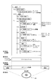
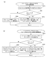
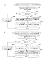
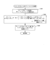
- FIG. It is a flowchart which shows an example of the process sequence of the display mode setting at the time of title switching. It is a flowchart which shows an example of the process sequence of the display mode setting in a title.
- 14 is a flowchart illustrating an example of a main procedure of playlist reproduction in the BD-J mode. It is a flowchart which shows an example of the reproduction
- FIG. 1 It is a flowchart which shows an example of the processing procedure of 3D display of a 3DAV stream. It is a flowchart which shows an example of the procedure of the process for left eyes at the time of 3D display mode. It is a flowchart which shows an example of the process sequence of the process for right eyes.
- (A) is a figure for demonstrating an example of the specific process of step S702 and step S804a
- (b) is a figure for demonstrating an example of the specific process of step S804b.
- (A) is a figure for demonstrating an example of the specific process of step S704a
- (b) is a figure for demonstrating an example of the specific process of step S806a.
- step S804b is a diagram for describing an example of specific processing of step S804b in the second embodiment. It is a block diagram which shows an example of an internal structure of the plane shift engine 20 of the reproducing
- (A) is a figure for demonstrating an example of the specific process of step S702 in Embodiment 2
- (b) is a figure for demonstrating an example of the specific process of step S804a. It is a figure which shows an example of the condition which intended moving the coordinate of the moving image and graphics which were scaled by the predetermined number of pixels. It is a block diagram which shows an example of an internal structure of the plane shift engine 20 of the reproducing
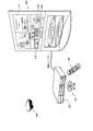
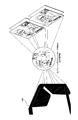
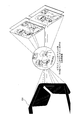
- FIG. 1 is a diagram showing an example of a usage behavior of a recording medium and a playback device.
- the BD-ROM 100 and the playback device 200 as an example of a recording medium constitute a home theater system together with a remote controller 300, a television 400, and liquid crystal glasses 500, and are used by a user.
- BD-ROM 100 supplies, for example, movie works to the home theater system.
- the playback device 200 is connected to the television 400 and plays back the BD-ROM 100.
- the reproduced video reproduced in this way includes 2D video and 3D video.
- the 2D video is an image expressed by pixels at the display position of the display screen located on the XY plane, for example, by regarding the plane including the display screen of the display device as the XY plane, and is also called a planar view image.
- a 3D image has a straight line perpendicular to the plane captured as the XY plane described above as an axis (in this embodiment, a straight line perpendicular to the XY plane is defined as an axis (Z axis)), and display on the display device
- the image is made to look three-dimensional to the human eye, or to appear in front or behind the display screen. It is.
- the 3D video is, for example, a recording medium from which data (stream data) corresponding to a left-view video to be viewed with the left eye and a right-view video to be viewed with the right eye can be read via a virtual file system shown in FIG. (For example, the BD-ROM 100 or the local storage 1c shown in FIG. 4 to be described later, here, the BD-ROM 100 will be described as an example for the sake of simplicity.) If the right-view video to be viewed with the right eye is a video that looks different in the degree of parallax between both eyes, the left-view video is shown only to the left eye and the right-view video is shown only to the right eye.
- the left-view video By repeating the operation, it can be shown to the user as a stereoscopic image with depth to the human eye.
- it can be seen only as a planar video by human eyes.
- the left-view video is shown in both the left and right eyes, the left-view video can only be seen as a planar video by human eyes.
- the remote controller 300 is a device that accepts an operation on a hierarchical GUI from a user. To accept such an operation, the remote controller 100 moves a menu key for calling a menu constituting the GUI and a focus of a GUI component constituting the menu. An arrow key, a determination key for performing a confirmation operation on a GUI component constituting the menu, a return key for returning a hierarchical menu to a higher level, and a numerical key are provided.
- the television 400 provides a user with an interactive operation environment by displaying a playback image of a movie work or displaying a menu or the like.
- the display screen of the television 400 in this figure shows a display example in which the GUI is full screened by scaling the video.
- the right half of the screen of the television 400 displays the director's comment cm1 described by the director of the movie work.
- the lower half of the screen of the television 400 is the button member bn1 that accepts next skip and previous skip.
- a button member bn2 that accepts a menu call, a button member bn3 that accepts a return operation, a button member bn4 that accepts a network connection, and an indicator ir1 for displaying the current title number and the current chapter number.
- These button members can be operated by the remote controller 300.
- the liquid crystal glasses 500 are composed of a liquid crystal shutter and a control unit, and realize stereoscopic viewing using parallax in both eyes of the user.
- the liquid crystal shutter of the liquid crystal glasses 500 is a shutter using a liquid crystal lens having a property that light transmittance is changed by changing an applied voltage.
- the control unit of the liquid crystal glasses 500 receives a synchronization signal for switching between the right-view image and the left-view image output sent from the playback device, and switches between the first state and the second state according to the synchronization signal. I do.
- the first state is a state in which the applied voltage is adjusted so that the liquid crystal lens corresponding to the right view does not transmit light, and the applied voltage is adjusted so that the liquid crystal lens corresponding to the left view transmits light.
- a left-view image is provided for viewing on the left eye, and a left-view image is not provided for viewing on the right eye.
- the second state is a state in which the applied voltage is adjusted so that the liquid crystal lens corresponding to the right view transmits light, and the applied voltage is adjusted so that the liquid crystal lens corresponding to the left view does not transmit light.
- the right-view image is viewed for the right eye, and the right-view image is not viewed for the left eye.
- a right-view image and a left-view image are images that have a slight difference in appearance between the image seen from the right view and the image seen from the left view due to the difference in the shooting position. is there.
- the degree of difference in the appearance of the image as the degree of difference between the images seen from the left eye / right eye of the human (that is, the degree of parallax)
- the image seen from the human eye can be recognized as a three-dimensional image. It is. Therefore, if the liquid crystal glasses 500 synchronize the switching between the first state and the second state as described above with the output switching timing of the right-view image and the left-view image, the user can The illusion is that a typical display looks three-dimensional. Next, the time interval for displaying the right view video and the left view video will be described.
- This short time interval is sufficient as long as it is an illusion that a person can see three-dimensionally by the switching display described above.
- FIG. 2 is a diagram illustrating an example of the internal configuration of the BD-ROM 100.
- BD-ROM 100 which is an example of a recording medium, is shown in the fourth row of the figure, and tracks on the BD-ROM 100 are shown in the third row.
- the track in this figure is drawn by extending the track formed in a spiral shape from the inner periphery to the outer periphery of the BD-ROM 100 in the horizontal direction.
- This track includes a lead-in area, a volume area, and a lead-out area.
- BCA Burt Cutting Area
- the volume area in this figure has a layer model of a file system layer and an application layer, and application data such as video data is recorded in the file system layer with the file system information at the top.
- the file system is UDF, ISO9660, etc., and logical data recorded in the same way as a normal PC can be read out using a directory and file structure, and a 255 character file name.
- the directory name can be read out.
- the disk root certificate file (app.discroot.cert) exists under the CERTIFICATE directory.
- app.discroot.cert is a Java (registered trademark) application that performs dynamic scenario control using a Java (registered trademark) virtual machine. It is a digital certificate used in the process of performing (hereinafter referred to as signature verification).
- the BDMV directory is a directory in which data such as AV contents and management information handled by the BD-ROM 100 is recorded.
- Under the BDMV directory there are a PLAYLIST directory, a CLIPINF directory, a STREAM directory, a BDJO directory, a JAR directory, a META directory, and so on.
- the STREAM directory is a directory that stores a file that is the main body of the transport stream, and is a file with an extension m2ts (00001. m2ts) exists.
- the CLIPINF directory contains a file (00001.clpi) with the extension clpi.
- the BDJO directory contains a file (XXXXX.bdjo) with the extension bdjo.
- the JAR directory contains a file (YYYYY.jar) with the extension jar.
- the XML file (ZZZZZ.xml) exists in the META directory.
- a file with the extension m2ts is a digital AV stream in the MPEG-TS (TransportStream) format, and is obtained by multiplexing a video stream, one or more audio streams, and a graphics stream.
- the video stream indicates the moving image portion of the movie
- the audio stream indicates the audio portion of the movie.
- a transport stream including only a 2D stream is referred to as a “2D stream”, and a transport stream including a 3D stream is referred to as a “3D stream”.
- both left-eye data and right-eye data can be put in m2ts, and m2ts can be prepared separately for the left eye and the right eye.
- a codec for example, MPEG-4 in which the left-view video stream and the right-view video stream cross-reference each other is used.
- AVC MVC A video stream compression-encoded with such a codec is referred to as an MVC video stream.
- a file with the extension “mpls” is a file storing PlayList (PL) information.
- the playlist information is information that defines a playlist with reference to an AV clip.
- the BD-ROM 100 has a dimension identification flag for identifying whether the stream to be played is for 2D or 3D.
- the dimension identification flag is embedded in the playlist (PL) information.
- Playlist information includes MainPath information, Subpath information, and PlayListMark information.
- MainPath information is information that defines a logical playback section by defining one or more combinations of a time point that becomes In_Time and a time point that becomes Out_Time on the playback time axis of the AV stream.
- the stream number table (STN_table) that defines which of the elementary streams multiplexed in the above is permitted and which is not permitted.
- the PlayListMark information includes designation of a time point to be a chapter among a part of the AV stream designated by the combination of In_Time information and Out_Time information.
- Subpath information is composed of one or more pieces of SubPlayItem information.
- SubPlayItem information includes designation of an elementary stream to be reproduced in synchronization with the AV stream, In_Time information and Out_Time on the reproduction time axis of the elementary stream. Information set.
- AV playback can be started by a Java TM application for playback control instructing the Java TM virtual machine to generate a JMF player instance that plays back this playlist information.
- a JMF (Java Media Frame work) player instance is actual data generated on a heap memory of a virtual machine based on a JMF player class.
- a 2D playlist includes only a 2D playback stream
- a 3D playlist includes a 3D stereoscopic stream in addition to a 2D stream.
- a file with the extension “clpi” is Clip information corresponding to each AV clip on a one-to-one basis. Because of the management information, the Clip information has information such as a stream encoding format, a frame rate, a bit rate, and a resolution in the AV clip, and an EP_map indicating a GOP head position.
- the above Clip information and playlist information are classified as “static scenarios”.
- a file with the extension BDJO is a file storing a BD-J object.
- the BD-J object is information that defines a title by associating an AV clip string defined by playlist information with an application.
- the BD-J object indicates “application management table” and “reference value for playlist information”. “Reference value for play list information” indicates play list information to be reproduced simultaneously with the start of the title.
- the application management table is a list of information designating applications having this title as a life cycle.
- a character string indicating the name of the application and an icon locator indicating the location of the icon associated with the application are stored for each application.
- the icon locator indicates an icon included in the Java (registered trademark) archive file by an address.
- the Java (registered trademark) application is actually the Java (registered trademark) archive file (YYYYY.jar) stored in the JAR directory under the BDMV directory in FIG.
- the application is, for example, a Java (registered trademark) application, and includes one or more xlet programs loaded in the heap area (also called work memory) of the virtual machine.
- Application signaling is performed according to the application management table in the BD-J object, and the life cycle is managed, so it is called a BD-J application.
- the BD-J application is intended to improve interactivity, and in order to operate the BD-J application, the playback device platform has a scaling command that uses the scaling size (hereinafter referred to as scaling factor) as input information.
- scaling factor scaling factor
- APIs that can be issued are defined.
- the timing of issuing the scaling instruction is arbitrary, and it may be issued during playback of the video stream, or at other timings.
- the metafile (ZZZZZ.xml) stored in the META directory stores various information related to video works on the disc.
- Information stored in the metafile includes the disc name and image of the disc, information on who created the disc, the title name associated with each title, and the like. This completes the description of the BD-ROM 100.
- the metafile is not an essential file, and some BD-ROMs do not store this file.
- FIG. 3 is a diagram illustrating an example of an internal configuration of a BD-J object.
- the BD-J object is composed of an “application management table”, a “GUI management table”, and a “playlist management table”.
- AMT Application management table
- AMT Application management table
- a lead line bj1 shows a close-up of the internal configuration of the application management table.
- the application management table includes an “application identifier” that identifies an application to be operated when a title corresponding to the BD-J object becomes the current title, and a “control code”.
- the control code indicates that this application is loaded into the heap memory and then automatically started.
- this application is loaded into the heap memory and then another application Wait for a call from, indicating that it should be activated.
- GUI management table is a management table used when a running application performs GUI, and the resolution, GUI font data, GUI menu call, and title call for GUI display are executed by the user. Contains a mask flag that specifies whether to mask these calls.
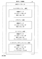
- a lead line bj2 shows a close-up of the internal configuration of the GUI management table. As shown in the lead line bj2, the GUI management table should be set to one of HD3D_1920 ⁇ 1080, HD3D_1280 ⁇ 720, HD_1920 ⁇ 1080, HD_1280 ⁇ 720, QHD960 ⁇ 540, SD, SD_50HZ_720 ⁇ 576, SD_60HZ_720 ⁇ 480. Can do.
- Playlist management table includes designation of a playlist to be automatically played when the title corresponding to the BD-J object becomes the current title.
- a lead line bj4 shows a close-up of the internal structure of the automatic playback playlist. As shown in the leader line bj4, 3D playlist 1920 ⁇ 1080, 3D playlist 1280 ⁇ 720, 2D playlist 1920 ⁇ 1080, 2D playlist 1280 ⁇ 720, 2D playlist 720 are used to specify the automatic playback playlist. * 576 and 2D playlist 720 * 480 can be specified.
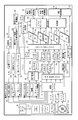
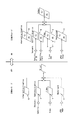
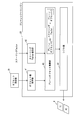
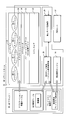
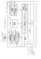
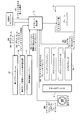
- FIG. 4 is a diagram showing an example of the internal configuration of the playback apparatus.
- the playback apparatus includes a BD drive 1a, local storage 1b, network interface 1b, local storage 1c, read buffers 2a and 2b, virtual file system 3, demultiplexer 4, video decoders 5a and 5b, video.
- Plane 6 image decoders 7a, 7b, image memories 7c, 7d, image plane 8, audio decoder 9, interactive graphics plane 10, background plane 11, register set 12, static scenario memory 13, playback control engine 14, scaling engine 15, composition unit 16, HDMI transmission / reception unit 17, display function flag holding unit 18, left-right processing storage unit 19, plane shift engine 20, offset setting unit 21, BD-J platform 22, rendering engine 22a, dynamic scenario menu Li 23, the mode management module 24, HDMV module 25, UO detection module 26, a still image memory 27a, a still image decoder 27b, a display mode setting initial display setting unit 28, a display mode storage unit 29.
- the BD-ROM 100 stores data having a file structure as shown in FIG. 2, and a left-eye video stream and a right-eye video from a virtual BD-ROM (virtual package) described later.
- a stream, a caption stream, and a graphics stream can be read out via the virtual file system 3 shown in FIG.
- the subtitle stream and the graphics stream those for the left eye and the right eye may be recorded on the BD-ROM 100, respectively, or one subtitle stream and the graphics stream may be shared between the left and right.
- the subtitles and graphics that can be seen through the liquid crystal glasses 500 are two-dimensional images, but they can be seen at a position protruding from the display screen or behind the display screen. Can appear to be located.
- Each of the left-eye video stream and the right-eye video stream recorded on the BD-ROM 100 is input to the playback device 200 and played back.
- the data for reproducing such a video is recorded in the BD-ROM 100 in advance as a video stream.
- the right-eye video stream, the left-eye video stream, the subtitle stream, and the graphics stream are embedded in one stream file in advance. This is to suppress as much as possible the amount of computation required by a device (for example, a CE device) having a small device resource in memory or graphics.
- a device for example, a CE device
- the BD drive 1a includes, for example, a semiconductor laser (not shown), a collimator lens (not shown), a beam splitter (not shown), an objective lens (not shown), a condenser lens (not shown), and a photodetector (not shown). And an optical head (not shown).
- the light beam emitted from the semiconductor laser passes through the collimator lens, the beam splitter, and the objective lens, and is condensed on the information surface of the optical disk.
- the condensed light beam is reflected / diffracted on the optical disk, and is collected on the photodetector through the objective lens, the beam splitter, and the condenser lens.
- the generated signal corresponds to the data read from the BD-ROM according to the amount of light collected by the photodetector.
- the network interface 1b is for communicating with the outside of the playback device, and can access a server accessible via the Internet or a server connected via a local network. For example, it can be used to download additional BD-ROM content published on the Internet, or data communication can be performed with a server on the Internet specified by the content, enabling content playback using the network function.
- the BD-ROM additional content is content that is not in the original BD-ROM 100 loaded in the BD drive 1a, and includes, for example, additional sub audio, subtitles, privilege video, and applications.
- the network interface 1b can be controlled from the BD-J platform, and additional content published on the Internet can be downloaded to the local storage 1c.
- the local storage 1c includes built-in media and removable media, and is used for storing downloaded additional content and data used by applications.
- the storage area for additional content is divided for each BD-ROM, and the area that an application can use to hold data is divided for each application.
- merge management information in which merge rules describing how the additional content downloaded is merged with the data on the BD-ROM loaded in the BD drive 1a is also stored in the built-in and removable media.
- Build-in media is a writable recording medium such as a hard disk drive or memory built in the playback device.
- the removable media is, for example, a portable recording medium, and preferably a portable semiconductor memory card such as an SD card.
- the playback device has a slot (not shown) for attaching a removable medium and an interface (for example, a memory card I) for reading the removable medium installed in the slot. / F), and when a semiconductor memory is installed in the slot, the removable media and the playback device are electrically connected and recorded in the semiconductor memory using an interface (for example, a memory card I / F). Data can be converted into an electrical signal and read out.
- the read buffer 2a is a buffer for temporarily storing source packets constituting extents constituting the left-view stream read from the BD drive 1a, adjusting the transfer speed, and transferring the packets to the demultiplexer 4. .
- the read buffer 2b is a buffer for temporarily storing source packets constituting extents constituting the right-view stream read from the BD drive 1a, adjusting the transfer speed, and transferring the packets to the demultiplexer 4. .
- the virtual file system 3 is a virtual BD obtained by merging the additional content stored in the local storage and the content on the loaded BD-ROM based on, for example, merge management information downloaded to the local storage 1c together with the additional content.
- -Build a ROM virtual package.
- the virtual file system 3 for building a virtual package has an application data association module for generating and updating application association information.
- the application data association information is information that associates local storage information with an application based on information on the BD-ROM disc and attribute information set by the application.
- the virtual package and the original BD-ROM can be referenced without distinction from the command interpreter, which is the main operating entity in HDMV mode, and the BD-J platform, which is the main operating entity in the BD-J mode.
- the playback device performs playback control using both data on the BD-ROM and data on the local storage.
- the demultiplexer 4 is composed of, for example, a source packet depacketizer and a PID filter, and a stream to be reproduced (a stream is a virtual package constructed (data on a local storage corresponding to a loaded BD-ROM and a loaded BD-ROM)) And packet filtering based on the packet identifier is executed.
- packet filtering a video stream corresponding to the display method flag is extracted from the left-view video stream and the right-view video stream based on the flag of the left / right processing storage unit 19 and transferred to the video decoder 5a and the video decoder 5b.
- the demultiplexer 3 sorts the left-eye video frame and the right-eye video frame from the stream header information.
- the demultiplexer 4 When the stream separated from the reproduction target stream is a subtitle stream, the demultiplexer 4 writes the separated subtitle stream in the image memory. For example, when a 3D subtitle stream (left view subtitle stream, right view subtitle stream) is included in the stream, the left view subtitle stream is written in the image memory 7c, and the right view subtitle stream is written. Write to image memory 7d.
- a 3D subtitle stream left view subtitle stream, right view subtitle stream
- the subtitle stream includes a 2D subtitle stream (a subtitle stream used for flat display)
- the 2D subtitle stream is written in the image memory 7c.
- Video decoder 5a The video decoder 5a decodes the TS packet output from the demultiplexer 4 and writes an uncompressed picture into the left-view video plane 6 (indicated by the code (L) in the video plane 6 in FIG. 4).
- Video decoder 5b The video decoder 5b decodes the right-view video stream output from the demultiplexer 4, decodes the TS packet, and converts the uncompressed picture into the right-view video plane 6 (the code (R) in the video plane 6 in FIG. 4). Write to what is shown.
- the video plane 6 is a plane memory that can store picture data corresponding to a resolution of, for example, 1920 ⁇ 2160 (1280 ⁇ 1440), and is a plane for the left eye having a resolution of 1920 ⁇ 1080 (1280 ⁇ 720) (FIG. 4). ) And a right-eye plane having a resolution of 1920 ⁇ 1080 (1280 ⁇ 720) (denoted by the symbol (R) in the video plane 6 in FIG. 4).
- the image decoders 7a and 7b decode TS packets that are output from the demultiplexer 4 and are written in the image memories 7c and 7d, and write uncompressed graphics subtitles to the graphics plane 8a.
- the “subtitle stream” decoded by the image decoders 7a and 7b is data representing a subtitle compressed by run-length encoding, a pixel code indicating a Y value, a Cr value, a Cb value, and an ⁇ value, and the pixel code Defined by run length.
- the image plane 8 is a graphics plane that can store graphics data (for example, caption data) obtained by decoding a caption stream with a resolution of, for example, 1920 ⁇ 1080 (1280 ⁇ 720), for example, 1920 ⁇ 1080.
- graphics data for example, caption data
- Left-eye plane (indicated by the symbol (L) in the image plane 8 shown in FIG. 4) having a storage area capable of storing data having a resolution of (1280 ⁇ 720), 1920 ⁇ 1080 (1280 ⁇ 720)
- a right-eye plane (indicated by reference numeral (R) in the image plane 8 shown in FIG. 4) having a storage area capable of storing data having a resolution of.
- the audio decoder 9 decodes the audio frame output from the demultiplexer 4 and outputs uncompressed audio data.
- the interactive graphics plane 10 is a graphics plane having a storage area in which graphics data drawn by the BD-J application using the rendering engine 22a can be stored with a resolution of 1920 ⁇ 1080 (1280 ⁇ 720), for example.
- 1920 ⁇ 1080 A plane for the right eye having a storage area capable of storing data having a resolution of 1280 ⁇ 720) (indicated by reference numeral (R) in the interactive graphics plane 10 of FIG. 4).
- “Graphics data” stored in the interactive graphics plane 10 is a graphic in which each pixel is defined by an R value, a G value, a B value, and an ⁇ value. Graphics written in the interactive graphics plane 10 are images and widgets having a purpose mainly used for configuring a GUI. Although there is a difference in data representing pixels, image data and graphics data are included in the expression graphics data.
- graphics planes There are two types of graphics planes that are the subject of the present application: an image plane 8 and an interactive graphics plane 10. When simply called “graphics planes”, they indicate either or both of the image plane 8 and the interactive graphics plane 10. To do.
- the background plane 11 is a plane memory that can store still image data to be a background image with a resolution of 1920 ⁇ 1080 (1280 ⁇ 720), for example, specifically, 1920 ⁇ 1080 (1280 ⁇ 720).
- the register set 12 includes a playback state register that stores the playback state of the playlist, a playback setting register that stores configuration information indicating the configuration of the playback device, and a general-purpose register that can store arbitrary information used by the content. It is a gathering of.
- the reproduction state of the playlist indicates a state such as which AV data is used in various AV data information described in the playlist and which position (time) of the playlist is being reproduced.
- the playback control engine 14 stores the contents in the PSR set 12. Also, the value specified by the application can be stored or the stored value can be stored in the application according to the instruction from the command interpreter that is the HDMV mode operation subject or the Java platform that is the BD-J mode operation subject. It is possible to pass
- the static scenario memory 13 is a memory for storing current playlist information and current clip information.
- Current playlist information refers to information that is currently processed among multiple playlist information that can be accessed from a BD-ROM, a built-in media drive, or a removable media drive.
- Current clip information refers to information that is currently processed among a plurality of clip information that can be accessed from a BD-ROM, a built-in media drive, or a removable media drive.
- the playback control engine 14 executes an AV playback function and a playlist playback function in response to a function call from a command interpreter that is an HDMV mode operating entity and a Java platform that is an BD-J mode operating entity.
- the AV playback function is a group of functions followed from DVD players and CD players. Playback start, playback stop, pause, release of pause, release of still image function, fast forward with specified playback speed, playback speed Is a process such as rewind, audio switching, sub-video switching, angle switching, etc., designated as an immediate value.
- the playlist playback function refers to performing playback start and playback stop in accordance with current playlist information and current clip information constituting the current playlist in the AV playback function.
- the playlist and AV stream that are subject to playback processing by the playback control engine 12 are the automatic playback playlist described in the current scenario on the BD-ROM. (AutoStartPlaylist).
- AV stream playback may be triggered by a user operation (for example, a playback button) or automatically triggered by some event in the terminal.
- the scaling engine 15 can perform reduction, enlargement, and equal magnification control of the video on the image plane 8 and the video plane 5. If the value is set in the plane shift engine 20 when the image data and picture data are decoded, the scaling engine 15 regards that scaling has occurred, and stores the decoded video data in the video plane. Before the decoded graphics are stored in the image plane, scaling is performed through the scaling engine 15.
- the scaling factor is, for example, the magnification of the number of horizontal pixels and / or the magnification of the number of vertical pixels. For example, a scaling factor of “1/2” is applied to graphics data whose basic resolution is 1920 ⁇ 1080 pixels. When Factor is specified, the resolution of the graphics data is reduced to (1920 ⁇ 0.5) ⁇ (1080 ⁇ 0.5) pixels, that is, 960 ⁇ 540 pixels.
- the scaling factor can be set not only to a value of 1 or less, but also to a value of 1 or more, as in 1/2, in which case enlargement processing is performed. (Synthesis unit 16)
- the combining unit 16 combines the stored contents of the interactive graphics plane 10, the image plane 8, the video plane 6, and the background plane 11.
- the interactive graphics plane 10, the image plane 8, the video plane 6, and the background plane 11 have separate layer configurations, and the background plane 11, the video plane 6, the image plane 8, and the interactive graphics plane are always in order from the bottom. Combine (superimpose) the stored data. Assuming playback of content that displays subtitles as image plane data, POP-UP menu (graphics) as interactive graphics plane 10 data, and GUI graphics data, the synthesizing unit must ensure that the video plane 6 data ( The image plane 8 data (caption) is superimposed on the video), and the interactive graphics plane 10 data is superimposed on the image plane 8.
- the HDMI transmission / reception unit 17 includes, for example, an interface conforming to the HDMI standard (HDMI: High Definition Multimedia Interface), and performs transmission / reception so as to conform to the HDMI standard with a playback apparatus and a device that is HDMI-connected (in this example, the television 400).
- the picture data stored in the video and the uncompressed audio data decoded by the audio decoder 9 are transmitted to the television 400 via the HDMI transmission / reception unit 16.
- the television 400 holds, for example, information regarding whether it is compatible with stereoscopic display, information regarding resolution capable of planar display, and information regarding resolution capable of stereoscopic display, and there is a request from the playback device via the HDMI transmission / reception unit 16.
- the television 400 returns the requested necessary information (for example, information regarding whether or not stereoscopic display is supported, information regarding resolution capable of planar display, information regarding resolution capable of stereoscopic display) to the playback device.
- information regarding whether or not the television 400 is compatible with stereoscopic display can be acquired from the television 400 via the HDMI transmission / reception unit 16.
- the display function flag storage unit 18 stores a 3D display function flag indicating whether or not the playback apparatus can display 3D.
- the left-right process storage unit 19 stores whether the current output process is a left-view output or a right-view output.
- the flag in the left / right processing storage unit 19 indicates whether the output to the display device (the television in the example of FIG. 1) connected to the playback apparatus shown in FIG. 1 is a left view output or a right view output. While the left view is output, the flag in the left / right processing storage unit 19 is set to a flag indicating the left view output. During the right view output, the flag in the left / right processing storage unit 19 is set to a flag indicating the right view output.
- the plane shift engine 20 also has an area for storing a plane offset. After determining whether the current processing target is a left-eye image or a right-eye image in the left-right processing storage unit 19, the horizontal axis of the image plane is stored using the stored plane offset. Shift amount (amount indicating how much the image displayed on the display screen is shifted from the reference position in the horizontal direction of the display screen) is calculated and shifted. By adjusting the shift amount of the displayed subtitles (graphics), the planar subtitles (graphics) seen through the liquid crystal glasses 500 may appear to be displayed in front / back of the display screen position. it can. The shift amount is an amount for adjusting how far from the position of the display screen it seems to be located in front or behind.
- the depth is changed by changing the shift width of the horizontal axis of subtitles / graphics.
- the left-eye caption and the right-eye caption are displayed so that the farther apart they are in a certain direction, the closer to the front, and the farther away they are in the opposite direction, the farther they are separated, the deeper the visual effect is displayed. It is done.
- the displacement of the image plane may become too large, resulting in a phenomenon where the image is not visible and looks double.
- the resolution and size information of the display is combined based on the value described in the plane offset, and adjustment is performed so that subtitles and graphics are not displayed too far in front.
- the plane shift engine 20 stores the value set using the setup function.
- Offset setting unit 21 The offset setting unit 21 sets an offset to be updated when there is an offset update request in an offset value storage unit 41 of the plane shift engine 20 described later.
- an image plane setting offset value and an interactive graphics plane setting offset value stored in a display mode storage unit 29 described later are read and set, and (b) input to the demultiplexer 4.
- the demultiplexer 4 acquires the offset value of the image plane and the interactive graphics plane held in the header area of the stream, and sets the above-described offset value obtained from the demultiplexer 4.
- UO The image plane offset value and interactive graphics plane offset value sent from the detection module 26 are read and set, (d) the image plane offset value included in the current playlist information, and the interactive graph Setting is made by the operation such as setting by reading the offset value of Kkusupuren.
- the plane offset is an integer whose depth is represented by ⁇ 63 to 63 (63 is the foremost and ⁇ 63 is the farthest), and is converted into pixel coordinates indicating the final shift width.
- the BD-J platform 22 is a Java platform that is an operation subject of the BD-J mode, and Java2Micro_Edition (J2ME) Personal Basis Profile (PBP 1.0) and Globally Executable MHP
- J2ME Java2Micro_Edition
- PBP 1.0 Java2Micro_Edition
- GEM1.0.2 for package media targets is fully implemented, and the BD-J application is started by reading the bytecode from the class file existing in the JAR archive file and storing it in the heap memory. Then, the byte code constituting the BD-J application and the byte code constituting the system application are converted into native codes and executed by the MPU.
- the BD-J platform 22 When scaling is requested from the BD-J application, the BD-J platform 22 stores the scaling factor given as an argument in the scaling factor storage unit 42 of the scaling engine 20 shown in FIG. 21 described later (rendering engine 22a).
- the rendering engine 22a includes basic software such as Java2D and OPEN-GL, and writes graphics and character strings to the interactive graphics plane 10 in accordance with instructions from the BD-J platform 22 in the BD-J mode.
- the rendering engine 22 a In the HDMV mode, the rendering engine 22 a renders graphics data extracted from a graphics stream other than the stream corresponding to the caption (caption stream) (for example, graphics data corresponding to the input button), and writes it to the interactive graphics plane 10.
- the dynamic scenario memory 23 is a memory that stores a current dynamic scenario and is used for processing by an HDMV module that is an HDMV mode operating subject and a Java platform that is an BD-J mode operating subject.
- the current dynamic scenario refers to an index.bdmv, BD-J object, or movie object that is currently being executed among BD-ROM, built-in media, and removable media.
- the mode management module 24 holds Index.bdmv read from the BD-ROM 100 or the local storage 1c (in the example of FIG. 4, a built-in media drive or a removable media drive), and performs mode management and branch control.
- the mode management by the mode management module 24 is a module assignment that determines which of the BD-J platform 22 and the HDMV module 25 is to execute a dynamic scenario.
- the HDMV module 25 is a DVD virtual player that is an operation subject in the HDMV mode, and an execution subject in the HDMV mode.
- This module has a command interpreter and executes HDMV mode control by decoding and executing navigation commands constituting the movie object. Since navigation commands are described in a syntax similar to DVD-Video, DVD-Video-like playback control can be realized by executing such navigation commands.
- the UO detection module 26 receives a user operation for the GUI.
- User operations accepted by the GUI include title selection, subtitle selection, and audio selection as to which title is selected from among the titles recorded on the BD-ROM.
- a level of depth perception of a stereoscopic image may be received. For example, there are cases where the sense of depth is three levels such as far, normal, and close, and the depth sense is accepted by numerical input such as how many centimeters and how many millimeters the sense of depth is.
- the UO detection module 26 receives a command for changing the scaling of the image plane by operating a button attached to the remote controller or the device, the module in the device directly issues a scaling command.
- the still image memory 27a stores still image data serving as a background image extracted from the BD-ROM or the constructed virtual package.
- the still image decoder 27 b decodes the still image data read to the still image memory 27 a and writes uncompressed background image data to the background plane 11.
- the display mode setting initial display setting unit 28 sets the display mode and resolution based on the BD-J object in the current title provided to the BD-J platform unit.
- the display mode storage unit 29 stores whether the display mode is 2D or 3D, and whether the stereo mode is ON or OFF.
- the playback device is set as a 3D display function flag to enable 3D display
- the display mode which is the terminal setting stored in the display mode storage unit 29, can be switched to either 2D or 3D.
- a state where the display mode is indicated as “3D” is referred to as “3D display mode”
- a state where the display mode is indicated as “2D” is referred to as “2D display mode”.
- each plane takes either a stereo mode ON state or a stereo mode OFF state.
- the difference between ON and OFF of the stereo mode is also the difference in the method of combining the planes.
- stereo mode ON means that the playback device has two images with different views (for example, a viewing angle) (for example, a left-view image and a right-view image with different viewing angles in the degree of parallax). This is a 3D display mode in which composition is performed using each video for view).
- Step mode OFF means that the playback device has one video (for example, one of a left-view video and a right-view video, and an example using a left-view video will be described here).
- This is a 3D display mode in which the composition is used for left eye / right eye using. In other words, when viewing with both eyes, the image has no stereoscopic effect (planar image).
- the horizontal graphics data (caption data) stored and displayed in the graphics plane is shown to be positioned in front of or behind the display screen due to a shift in the horizontal direction due to the plane offset.
- “3D display mode” there are two modes, “stereo mode ON” and “stereo mode OFF”.
- “3D display mode” in “stereo mode ON”, left view data and right view Data (for example, an image seen from the left eye and an image seen from the right eye at different angles) are stored in the left view plane and the right view plane, respectively, and the stored images are synchronized signals.
- stereo mode OFF in “3D display mode”, only one of left view data and right view data (for example, left view data in this embodiment) is used. By storing this in each of the left view plane and right view plane and adjusting the plane offset, it is possible to display a planar image so that it is positioned in front of or behind the display screen. Is possible.
- stereo mode ON and “stereo mode OFF” are configured to be set for each plane (that is, for each video plane 6, graphics plane 8, interactive graphics plane 10, and background plane 11). is doing.
- the “2D display mode” is a normal display, that is, an image corresponding to the position of the display screen is displayed.
- a decoder and a plane to be used as defaults are determined in advance, and a composition image is displayed using the decoder and the plane.
- 2D video data written by the video decoder 5a on the left-eye video plane (indicated by the symbol (L) in the video plane 6 shown in FIG. 4)
- the image decoder 7a is used for the left eye.
- 2D graphics data (caption data) written on the plane (denoted by the symbol (L) in the image plane 8 shown in FIG. 4)
- the BD-J application uses the rendering engine 22a to generate the left-eye plane (FIG. 4).
- 2D interactive graphics and still image decoder 27b written to the left graphics plane (the one with the symbol (L) in the background plane 11 shown in FIG. 4). Configured to synthesize 2D still image data written to Yes.
- composition is composed in the order of 2D still image data, 2D video data, 2D graphics data (caption data), and 2D interactive graphics from the bottom.
- the display mode setting initial display setting unit 28 sets the display mode and resolution based on the BD-J object in the current title provided to the BD-J platform unit.
- the video decoder 5a decodes the left-view video stream and outputs the left-eye plane (the video plane 6 shown in FIG. 5).
- the video decoder 5b decodes the right-view video stream, and the right-eye plane (shown by the code (R) in the video plane 6 shown in FIG. 5). Write to.
- the video decoder 5a decodes a left-view video stream, for example, and displays the left-eye plane (shown in FIG. 5). And the right-eye plane (denoted by the symbol (R) in the video plane 6 shown in FIG. 5).
- the demultiplexer 4 sends a 2D video stream to the video decoder 5a, and the video decoder 5a sends the decoded 2D video data to the left-eye video plane (FIG. 5).
- the video plane 6 shown in FIG. 4 is written in the code (L).
- the image decoder 7a decodes the left-view subtitle stream stored in the image memory 7c, and the left-eye plane ( The image decoder 7b decodes the right-view subtitle stream stored in the image memory 7d and writes the right-eye plane (shown in FIG. 5). (Indicated by the reference (R) in the image plane 8 shown).
- the image decoder 7a decodes the left-view subtitle stream stored in the image memory 7c, and uses the left-eye subtitle stream. Write to the plane (denoted by the symbol (L) in the image plane 8 shown in FIG. 5) and the right-eye plane (denoted by the symbol (R) in the image plane 8 shown in FIG. 5).
- the left-view subtitle stream is decoded and written to the left-eye plane and the right-eye plane. If the subtitle stream recorded on the recording medium shares the same subtitle stream on the left and right, the shared subtitle stream can be read and written to the left-eye image plane and the right-eye image plane. good.
- the demultiplexer 4 is configured to store the 2D subtitle stream in the image memory 7c, and the image decoder 7a is stored in the image memory 7c.
- the 2D subtitle stream is decoded and written to the left-eye plane (denoted by the code (L) in the image plane 8 shown in FIG. 5).
- the interactive graphics for the left eye and the interactive graphics for the right eye drawn by this drawing program are graphics in which the angles seen from each other are different so as to look like three-dimensional graphics.
- the BD-J application uses the rendering engine 22a to create the plane for the left eye (indicated by the reference (L) in the interactive graphics plane 10 of FIG. 4).
- the left-view interactive graphics are written into the right-eye plane (the interactive graphics plane 10 shown in FIG. 4 with the symbol (R) added).
- the BD-J application uses the rendering engine 22a to convert the interactive graphics for the left view into the code of the interactive graphics plane 10. Write to (L) and the code
- the BD-J application uses the rendering engine 22a to convert the 2D interactive graphics into the interactive graphics plane 10 (more specifically, the code (L) of the interactive graphics plane 10). It is configured to write to (the ones marked with).
- the still image decoder 27b stores the left-view still image data and the right-view data stored in the still image memory 27a.
- the still image data is decoded, the left-view still image data is the left-eye plane (the symbol (L) added to the background plane 11 shown in FIG. 4), and the right-view still image data is the right-eye plane. Each of them is written in (the one with the reference (R) in the background plane 11 shown in FIG. 4).
- the background image display mode is, for example, the 3D display mode and the stereo mode is off, the 3D background image (left view still image data, right view still image data) stored in the still image memory 27a.
- the still image decoder 27b decodes the left-view still image data, and the left-eye plane (with the symbol (L) in the background plane 11 shown in FIG. 4) and the right-eye plane (FIG. 4).
- the background image display mode is, for example, the 2D display mode
- the still image decoder 27b decodes the 2D still image data stored in the still image memory 27a, and the left-eye plane (the code in the background plane 11 shown in FIG. 4). (With (L)).
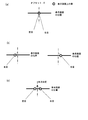
- FIG. 5 is a diagram showing switching between the 2D display mode and the 3D display mode.
- the output model in the 2D display mode is shown on the left side of the figure.
- the video plane 6, the image plane 8 (“Subtitle” in the figure), the interactive graphics plane 10, the background plane 11, and the output are each configured.
- the left view and the right view are used in common, and as a result, the same output is seen.
- the output model in 3D display mode is displayed on the right side of this figure.
- the video plane 6, the image plane 8 (“Subtitle” in the figure), and the interactive graphics plane 10 are divided into left view and right view, respectively.
- the picture data and graphics data to be stored are stored.
- the left view and right view outputs exist separately, and it is possible to provide different images for the left eye and the right eye, and as if the 3D object in the screen pops out to the front in the parallax It is possible to bring out 3D effects.
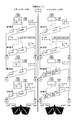
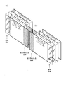
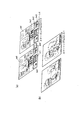
- FIG. 6 is a diagram illustrating an example of a synthesis process when the stereo mode of each plane is all on and the stereo mode is all off in the 3D display mode.
- FIG. 6 shows an example in which each plane unifies the stereo mode. However, ON / OFF of the stereo mode can be changed for each plane.
- the left side shows the plane configuration when all stereo modes of each plane are on in the 3D display mode
- the right side shows the plane configuration when all stereo modes of each plane are off in the 3D display mode.
- the first level shows the background plane 11 and the output before synthesis.
- the second row shows the video stream, the video plane 6, and the output before synthesis.
- the third row shows the image plane 8 and the output before synthesis.
- the fourth row shows the interactive graphics plane 10 and the output before synthesis.
- the background plane is indicated by the left-eye background plane indicated by the area indicated by (L) for writing the left-view background data, and indicated by the area indicated by (R).
- the right-eye background plane is written with the right-view background data, and is used when combining the left-eye / right-eye.
- the background data for the left view is written by the application in the areas with (L) and (R) in the background plane, so the background data for the right view is Does not affect the display.
- the stereo mode When the stereo mode is ON, the picture data of the left-eye video in the video stream is stored in the left-view video plane. Also, in the video stream, picture data of the right-eye video is stored in the right-view video plane. When the stereo mode of the video plane is OFF, the left-eye video picture data is stored in both the left-view video plane and the right-view video plane.
- the image data for the left view is written in the image plane for the left eye indicated by the area indicated by (L), and the image plane for the right eye indicated by the area indicated by (R) is displayed.
- Image data for right view is written and used for left eye / right eye composition respectively.
- the caption graphics corresponding to the image data for right view does not affect the display.
- the stereo mode is OFF, the contents of the image plane 8 are shifted to the right or left (Shifed in the figure). Left).
- the interactive graphics plane 10 is for left-eye interactive graphics planes written in the left-eye interactive graphics plane indicated by the region (L) and the right-eye indicated by the region (R).
- the interactive graphics for right view is written in the interactive graphics plane, and is used for the left eye / right eye composition, respectively.
- the stereo mode of the interactive graphics plane 10 is OFF, interactive graphics for writing by the application does not affect the display.
- the stereo mode is OFF, the content of the interactive graphics plane 10 is shifted to the right or left (Shifed Left in the figure).
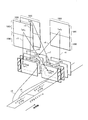
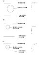
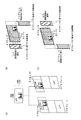
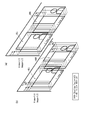
- FIG. 7 shows how the background plane 11, the video plane, the image plane 8, and the interactive graphics plane 10 are superimposed when the display mode is 3D and all the planes are in the stereo mode ON.
- the left view background plane u4 as the left view, the left view video u3 read from the video stream, the left view graphics u2 of the image plane 8, and the left view graphics u1 of the interactive graphics plane 10 are sequentially synthesized. I understand that.
- the right view background plane u8 as the right view, the right view video u7 read from the video stream, the right view graphics u6 of the image plane 8, and the right view graphics u5 of the interactive graphics plane 10 are sequentially combined. I understand.
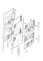
- FIG. 8 shows how the background plane 11, the video plane, the image plane 8, and the interactive graphics plane 10 are overlaid when the display mode is 3D and all the planes are in the stereo mode OFF.
- the left view background plane r4 as the left view
- the left view video r2 read from the video stream
- the left view graphics of the image plane 8 are shifted to a certain horizontal direction (right in the figure) ShiftedLeft
- ShiftedLeft It can be seen that the Shifted Left graphics r1 obtained by shifting the left view graphics of the graphics r3 and the interactive graphics plane 10 in a certain horizontal direction (right in the figure) is sequentially combined.
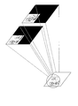
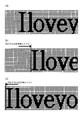
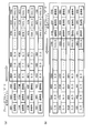
- FIG. 9 shows the synthesis result for each plane.
- 6L and 6R are examples of video planes.
- the difference in the orientation of the woman's face indicates that the left-view stream and the right-view stream were taken from different angles.
- the deviation of the face direction and position of the person in FIG. 9 is schematic and does not represent the exact face direction or position for realizing stereoscopic reproduction.
- the character “I love you” in the image plane 8 is an image after subtitle data is decoded by the image decoder.
- the GUI component that accepts the forward / backward skip operation in the interactive graphics plane 10 is a graphics image drawn on the interactive graphics plane 10 by the BD-J application.
- 6LL is an output left view after synthesis
- 6RR is an output right view output after synthesis.
- 6LL left-view video you can see that the subtitle “I“ love you ”is shifted to the right.
- 6RR right-view video the subtitle “I love you” is shifted to the left.
- FIG. 10 is an example of a case where the video output when all the planes are in the stereo mode is viewed on the 3D display.
- the video for the right view and the left view is filtered through, for example, the liquid crystal glasses 500 to display different images for the left and right eyes.
- the video stream video is not only three-dimensionalized with the left and right images superimposed, but also the GUI parts that accept subtitles for “I love you” and skip operations before and after are different for the left and right eyes. It is that. In this way, if both left-eye content and right-eye content are prepared in advance, turning on the stereo mode naturally makes it possible to maintain the depth of all video, subtitles, and GUI parts. .
- FIG. 11 shows an example of a stereoscopic video image that appears when the video output is viewed with the liquid crystal glasses 500 when the video plane is in the stereo mode ON but the other planes are all in the stereo mode OFF.
- Graphics plane stereo for discs that do not have subtitles or GUIs for both the left and right eyes past content created on the assumption of 2D, discs that have to do so due to lack of disk space, etc.
- the mode must be turned off.
- the video plane since the video plane is in the stereo mode ON, the images reproduced from the left view stream and the right view stream are the same subject to be photographed and reproduced from different angles. I can see that.
- the image plane 8 and the interactive graphics plane 10 are in stereo mode OFF, and the same subtitle stream and the same GUI image shifted in the right and left directions are combined into the video plane, and only the subtitle / GUI for one eye is used. Even if it does not exist, it can be displayed in front of the stereoscopic video, and it can be seen that the degree of eye fatigue on the viewer can be reduced.
- the direction in which the plane shift engine 20 shifts depends on whether the graphics plane has a stereoscopic effect that is located behind the display screen or has a stereoscopic effect that is positioned on the near side of the display screen.
- shift amount causes the subtitles written in the image plane 8 or the graphics image written in the interactive graphics plane 10 to be displayed so as to be positioned on the front or back of the display screen. Should be calculated by the depth value. Further, it can be derived from any parameter that can be adopted as parallax for both eyes in stereoscopic reproduction.
- plane offset a parameter for moving pixel data in the graphics plane to the left and right by the shift amount as described above.
- the shift amount is a scalar amount
- the plane offset is a vector with positive and negative polarities and magnitudes. From the normal state (that is, the state that appears to be displayed on the display screen), the display screen It indicates how much the coordinate of the pixel data is moved in which direction in the horizontal direction (for example, right direction and left direction). In the following description, it is assumed that the plane shift is executed according to this plane offset. Some plane offsets are obtained by adding a positive or negative sign to the shift amount, and others can be used as the shift amount after performing calculation by some function expression.
- the plane offset of the graphics plane indicates the number of pixels by which the pixel data coordinates stored in the right-view graphics plane and the pixel data coordinates stored in the left-view graphics plane are shifted. .
- the plane offset is “0”, it means that the graphics plane is not shifted, that is, it is displayed in a normal state (a state that appears to be displayed on the display screen).
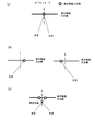
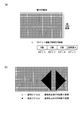
- FIG. 12 shows that when the display mode is 3D and the stereo mode of each plane is OFF, the plane offset of the background image stored in the background plane is “0”, and the plane offset of the video stored in the video plane is “0”.
- the plane offset of the image plane is” 0
- the graphics plane after the right shift is added with a transparent area on the left side and the right end is cut off.
- the graphics plane after the right shift is added with a transparent area on the left side and the right end is cut off.
- the graphics plane after the leftward shift is added with a transparent area on the right side and the left end is cut off.
- the graphics plane after shifting to the left is added with a transparent area on the right side and the left end is cut off.
- the plane shift executed when the stereo mode is OFF may make the graphics in the image plane or interactive graphics plane appear to be in front of the display screen or to be in the back of the display screen. It produces the visual effect of doing.
- the principle premised on this plane shift will be described.
- FIG. 13 shows that when the sign of the plane offset is positive (the left-view graphics image is shifted to the right and the right-view graphics image is shifted to the left), the image is in front of the display screen. It is a figure for demonstrating the visible principle.
- the stereo mode of the 3D display mode is OFF, the image that can be seen by the left eye is shifted and displayed so that it can be seen at the right position compared to the case where the plane offset is zero. At this time, nothing is visible to the right eye by the liquid crystal glasses 500. On the other hand, the image visible to the right eye is displayed so as to be shifted so that it can be seen on the left side compared to the case where the plane offset is zero. At this time, nothing is made visible to the left eye by the liquid crystal glasses 500 (FIG. 13B).
- ⁇ Human uses both eyes to focus and recognizes that there is an image at the focal position. Accordingly, when the liquid crystal glasses 500 alternately switch between a state in which an image can be seen by the left eye and a state in which the image can be seen by the right eye at short time intervals, both eyes of the human will attempt to adjust the focal position to a position in front of the display screen. As a result, an illusion is caused so that an image is present at the focal position located in front of the display screen (FIG. 13C).
- FIG. 14 shows that when the sign of the plane offset is negative (the left-view graphics image is shifted to the left and the right-view graphics image is shifted to the right), the image is behind the display screen. It is a figure for demonstrating the visible principle.
- FIG. 14 what is indicated by a circle is an image displayed on the display screen.
- the image seen by the right eye and the image seen by the left eye are at the same position, so the focal position when viewing this image using both eyes is located on the display screen (FIG. 14 ( a)).
- the resulting image is located on the display screen.
- the stereo mode of the 3D display mode is off, the image that can be seen by the left eye is made to appear on the left side as compared with the case where the plane offset is zero. At this time, nothing is visible to the right eye by the liquid crystal glasses 500. On the other hand, the image that can be seen by the right eye is made to appear on the right side as compared with the case where the offset is 0, and at this time, nothing is seen by the liquid crystal glasses 500 in the left eye (FIG. 14B).
- the human eyes try to adjust the focal position to a position deeper than the display screen. An illusion is caused so that there is an image at a position behind the display screen (FIG. 14C).
- FIG. 15 is a diagram illustrating an example of a difference in appearance between positive and negative plane offsets.
- (A) and (b) in the same figure show the right-view graphics image output using the shifted graphics plane shifted at the time of right-view output.
- the far side shows the graphics image for the left view that is output using the shifted graphics plane that is shifted when the left view is output.
- This figure (a) shows the case where the sign of the plane offset is positive (the graphics image for left view is shifted to the right and the graphics image for right view is shifted to the left). If the plane offset is a positive value, as shown in FIG. 13, the caption at the time of the left view output can be seen at the right position from the caption at the time of the right view output. That is, since the convergence point (focus position) comes to the front of the screen, the subtitles can also be seen to the front.
- This figure (b) shows the case where the sign of the plane offset is negative.
- the caption at the time of outputting the left view can be seen at the left position from the caption at the time of outputting the right view.
- the convergence point (focus position) goes deeper than the screen, the subtitles can also be seen deeper.
- FIG. 17 shows a stereoscopic image viewed by the user when the moving image is scaled.
- the display mode is 3D and the video plane stereo mode is ON, if the scaling factor “1/2” is scaled for a moving image, the horizontal and vertical widths are halved. It can be seen that a moving image having an area of 1/4 is stereoscopically displayed.
- the display mode is 3D and the video plane stereo mode is ON
- the images reproduced by the left-view video stream and the right-view video stream are images with different viewing angles. Therefore, when scaling is performed by the scaling factor, the degree of popping out by the stereoscopic display also dynamically changes according to the scaling factor.
- the plane offset is set to a value other than “0” in the image plane. If this is the case, this plane offset does not change dynamically due to scaling, so that the composite image has a strong sense of popping out subtitles, and the viewer feels uncomfortable.
- FIG. 18 shows a case where the plane offset of the image plane is not changed according to the video scaling when the display mode is 3D, the video plane stereo mode is ON, the display mode is 3D, and the image plane stereo mode is OFF. It is a figure for demonstrating what happens.
- the position where the subtitles are virtually seen is the position where the offset of the image plane is adjusted so that it appears in front of the virtual stereoscopic image.
- FIG. 18A shows a case where a full screen display is used
- FIG. 18B shows a case where a video is reduced.
- the degree of popping out of the video changes dynamically according to the degree of reduction.
- the position where the caption appears virtually is a fixed value given by the offset of the image plane, and the offset does not change due to the reduction process, so the offset of the image plane must be changed according to the scaling. , The subtitle position seems to pop out strangely.
- FIG. 19 shows an example schematically showing the pop-out degree shown in FIG.
- the playback device pays attention to this technical problem and provides a configuration to be solved.
- the playback apparatus is characterized in that the offset of the image plane is dynamically adjusted according to video scaling. Specifically, when the video is reduced and displayed as shown in FIG. 18 (c), the position where the subtitle can be virtually seen is made closer to the display screen side by adjusting the offset of the image plane (in this example, reducing the offset). .
- FIG. 19 shows a stereoscopic view displayed when the processing of the present embodiment is not performed, that is, when the moving image is reduced, or the plain offset before scaling specified by the user or the content is applied to the plane shift as it is. An image is shown.
- plane offset E which is obtained by multiplying the plane offset D used for synthesis with the unscaled moving image by the scaling factor
- plane offset E which is obtained by multiplying the plane offset D used for synthesis with the unscaled moving image by the scaling factor
- the plane offset D Since the plane offset D is multiplied by the scaling factor, the pop-out degree is reduced.
- the subtitles can be drawn to the vicinity of the scaled human figure. By doing so, subtitles exist near the scaled human figure, and the unbalanced feeling of the pop-up state between the human figure and the subtitles is eliminated.
- FIG. 20 shows a stereoscopic image displayed when the processing of the present embodiment is performed, that is, when the plane offset multiplied by the scaling factor is applied to the plane shift of the image plane.
- FIG. 20 differs from FIG. 19 in that subtitles exist near the scaled person image, and the unbalanced feeling of popping out of the person image and subtitles is eliminated.
- the plane shift engine 20 in FIG. 21 incorporates a mechanism for calculating the optimum plane offset in consideration of the scaling factor.
- the plane shift engine 20 will be described with reference to FIG.
- FIG. 21 is a diagram showing an example of the internal configuration of the plane shift engine 20 of the playback apparatus 200 according to the present embodiment.
- the plane shift engine 20 includes an offset value storage unit 41, a scaling factor storage unit 42, a plane offset calculation unit 43, and a shift unit 44.
- Offset value storage unit 41 The offset value storage unit 41 stores the content from the offset setting unit 21 or the offset value designated by the user.
- the scaling factor storage unit 42 stores magnification information from before the scaling. For example, a value such as “1” is stored when the scaling is not performed, a value “1/2” is stored when the image is half, and “2” is stored when the image is enlarged twice.
- the plane offset calculation unit 43 performs calculation for converting the shift amount to be shifted by the shift unit 44 into a pixel unit in consideration of scaling and screen size based on the offset value stored in the offset value storage unit 41.
- the scaling factor is specified as “1/2”
- the offset value stored in the offset value storage unit 41 is multiplied by the scaling factor stored in the scaling factor storage unit 42.
- the new value is obtained as a new “plane offset E”.
- the calculation by the plane offset calculation unit 43 involves multiplication with a scaling factor. In this case, handling of numerical values after the decimal point becomes a problem. This is because the shift amount must be an integer since the shift amount is shifted by a number corresponding to the number of pixels.
- the plane offset calculation unit 43 performs a calculation, when a numerical value after the decimal point appears in the calculation result, the numerical value after the decimal point is moved up to the next integer. For example, when the calculation result by the plane offset calculation unit 43 is “3.2”, it means that the calculation result is “4”.
- Ceil operation an operation that raises the fractional part of the operation result to the next integer.
- Ceil operation when an operation involving multiplication with a scaling factor is executed, a Ceil operation is executed on the operation result, and a part after the decimal point in the operation result is carried up to the next integer.
- the plane offset calculation unit 43 calculates the shift amount according to the scaling factor even when KEEP_RESOLUTION is set during scaling.
- the KEEP_RESOLUTION setting is a function for enlarging / reducing only the video plane without enlarging / reducing the interactive graphics plane at the time of a scaling command. By doing so, it is possible to change the subtitle depth in synchronization with the video depth even in KEEP_REOLUTION.
- the shift unit 44 performs shifting to the horizontal axis of the image plane based on the value calculated by the plane offset calculation unit 43.
- FIG. 22 is a diagram illustrating three scaling factors of 1/1, 1/2, and 1/4, and a composite image of graphics including subtitles and GUI when each scaling factor is applied.
- Scaling Factor 1/2, 1/4
- Scaling Factor 1/2, 1/4
- the scaling factor is 1/2, the number of vertical and horizontal pixels is 1/2, and it can be seen that it is displayed small on the left edge of the screen.
- the scaling factor is 1/4, the number of vertical pixels and the number of horizontal pixels is 1/4, and it can be seen that the image is displayed small at the left end of the screen.
- a moving image in which subtitles and GUI are combined is the target of scaling.
- the GUI is used for full-screen display.
- a composite image is arranged in the area.
- the GUI draws mainly in the part other than the part that displays the composite image of the caption and moving image displayed in the upper left area, the GUI is configured to be excluded from the scaling target. Only the synthesized image is the target of scaling.
- GUI is described as an example of interactive graphics data drawn by a BD-J application, but the interactive graphics data drawn by a BD-J application is not limited to a GUI, but is a graphic such as an animation linked to a moving image. Also included are images.
- the interactive graphics data drawn by the BD-J application can be scaled in conjunction with the reduction of subtitles / moving images if they are to be scaled in the same way as subtitles and moving images. You may do it.
- the background data stored in the background plane is displayed in the black portion of FIG.
- the subtitle shift amount is adjusted after scaling according to the size of the video plane as compared with the composition before scaling. As a result, it is possible to prevent the difference in stereoscopic effect from becoming intense, to reduce eye fatigue, and to perform more natural display.
- FIG. 24 is a diagram illustrating three scaling factors 1/1, 1/2, and 1/4, and a composite image of video and subtitle graphics when each scaling factor is applied.
- the right half of the screen of the television 400 represents the director's comment cm1 described by the director of the movie work, and the lower half of the screen of the television 400 accepts the button member bn1 that accepts the next skip and the previous skip, and the menu call. It includes a button member bn2, a button member bn3 that accepts a return operation, and a button member bn4 that accepts a network connection. These are the same as those shown in FIG.
- the target of scaling is a moving image synthesized with caption graphics
- the target of plane shift is only the image plane
- the target of calculation of the plane offset E is also only the plane offset E in the image plane.
- FIG. 26 shows an example of the internal configuration of the image plane 8.
- the image plane 8 is composed of a horizontal 1920 ⁇ vertical 1080 8-bit storage element as shown in FIG. This means a memory allocation that can store an 8-bit pixel code per pixel at a resolution of 1920 ⁇ 1080.
- the 8-bit pixel code stored in the storage element is converted into a Y value, a Cr value, and a Cb value by color conversion using a color lookup table.
- this color lookup table the correspondence between the pixel code and the Y value, Cr value, and Cb value is defined by the palette definition segment in the caption data.
- FIG. (B) in the figure shows pixel data stored in the image plane 8.
- the graphics data stored in the image plane 8 is composed of pixel data corresponding to the foreground part (part constituting the subtitle “I love”) and pixel data corresponding to the background part.
- a pixel code indicating a transparent color is stored in the memory element corresponding to the background portion, and a moving image on the video plane can be seen through this portion when the pixel code is combined with the video plane.
- the memory element corresponding to the foreground portion stores a pixel code indicating a color other than the transparent color
- the subtitle is drawn by the Y, Cr, and Cb values other than the transparent color.
- the portion corresponding to the transparent pixel can be seen through the background image stored in the background plane below the subtitles or the video content stored in the video plane. The presence of such a transparent portion enables plane synthesis.
- FIG. 27 shows the pixel data of the foreground area and the pixel data of the background area after the shift in the right direction and the shift in the left direction are performed.
- (A) is pixel data before shifting
- (b) is pixel data after shifting in the right direction.
- (C) is pixel data after the leftward shift.
- the shift amount is 15 pixels, it can be seen that the character “o” appears in the subtitle character “you” following the subtitle character “I love”.
- FIG. 28 shows the internal configuration of the interactive graphics plane 10.
- the interactive graphics plane 10 is composed of 32 bits long storage elements of horizontal 1920 ⁇ vertical 1080.
- the interactive graphics plane 10 has a memory allocation capable of storing 32-bit R, G, B, and ⁇ values per pixel at a resolution of 1920 ⁇ 1080.
- the 32-bit R, G, B, ⁇ values stored in the storage element are composed of an 8-bit R value, an 8-bit G value, an 8-bit B value, and an 8-bit transparency ⁇ .
- FIG. 10 shows pixel data stored in the interactive graphics plane 10.
- the graphics data stored in the interactive graphics plane 10 is composed of pixel data corresponding to the foreground part (GUI that accepts a skip operation to the preceding and following chapters) and pixel data corresponding to the background part.
- the alpha value indicating the transparent color is stored in the memory element corresponding to the background portion, and the subtitle of the image plane and the moving image on the video plane can be seen through this portion at the time of synthesis with the video plane. become.
- the storage element corresponding to the foreground portion stores R, G, B values indicating colors other than the transparent color, and graphics are drawn by the R, G, B values other than the transparent color.
- the contents of the background graphics plane, the video plane, and the image plane 8 can be seen through the portion corresponding to the transparent pixel, and the presence of the transparent portion enables plane synthesis. .
- FIG. 29 shows the pixel data of the foreground area and the pixel data of the background area after the shift in the right direction and the shift in the left direction are performed.
- This figure (a) is the pixel data before the shift
- this figure (b) is the pixel data after the shift in the right direction.
- the GUI that accepts the skip operation to the front and rear chapters has moved to the right.
- This figure (c) is pixel data after the leftward shift. It can be seen that the GUI that accepts skip operations to the previous and next chapters has moved to the left.
- FIG. 30 is a diagram showing a plane shift processing procedure in the image plane 8.
- (A) shows the left-shifted graphics plane and the right-shifted graphics plane generated from the image plane 8.
- (B) shows a shift in the right direction.
- the horizontal shifting method to the right is performed as follows (1-1) (1-2) (1-3).
- (1-1) Cut out the right end area of the image plane 8.
- (1-2) The position of the pixel data existing in the image plane 8 is shifted to the right by the shift amount indicated by the plane offset E in the horizontal direction as described above.
- (1-3) A transparent area is added to the leftmost end of the image plane 8.
- (C) indicates a shift in the left direction.
- the horizontal shifting method to the left is performed as follows (2-1) (2-2) (2-3).
- (2-1) Cut out the left end area of the image plane 8.
- (2-2) The position of each pixel data in the image plane 8 is shifted leftward by the shift amount indicated by the plane offset E in the horizontal direction. (2-3). Add a transparent area to the right edge of the image plane 8.
- the playback apparatus performs the synthesis after processing the plane as follows based on the shift amount indicated by the plane offset E.
- the left-view image plane 8 is shifted to the right by the shift amount indicated by the plane offset E before the synthesis of the planes. Then, the right-view image plane 8 is shifted to the left by the shift amount indicated by the plane offset E.
- the left-view image plane 8 is shifted to the left by the shift amount indicated by the plane offset E before the synthesis of the plane. Then, the right-view image plane 8 is shifted to the right by the shift amount indicated by the plane offset E.
- FIG. 31 is a diagram illustrating a processing procedure for plane shift in the interactive graphics plane 10.
- FIG. 31A illustrates a left-shifted graphics plane and a right-shifted graphics plane generated from the interactive graphics plane 10. Indicates.
- (B) shows a shift in the right direction.
- the horizontal shifting method to the right is performed as follows (1-1) (1-2) (1-3).
- (1-1) Cut off the right edge area of the interactive graphics plane.
- (1-2) The position of the pixel data existing in the interactive graphics plane is shifted by the shift amount indicated by the plane offset E in the horizontal direction to the right as described above.
- (1-3). Add a transparent area to the left end of the interactive graphics plane.
- (C) indicates a shift in the left direction.
- the horizontal shifting method to the left is performed as follows (2-1) (2-2) (2-3).
- the plane offset in the shift as described above is a value corresponding to the parallax between the right eye and the left eye. This means that the number of horizontal pixels of the area cut from the end of the graphics plane and the transparent area added to the end of the graphics plane must be the number of pixels corresponding to the plane offset E.
- the number of horizontal pixels in the region cut out from the edge of the graphics plane is the number of pixels corresponding to the shift amount of the plane offset E. Further, the number of vertical pixels in the transparent area is the number of pixels indicating the height of the graphics plane.
- the number of horizontal pixels in the transparent area added to the end of the graphics plane is the number of pixels corresponding to the shift amount of the plane offset E.
- the number of vertical pixels in the transparent area is the number of pixels indicating the height of the graphics plane.
- the playback device When the display mode is 3D and the stereo mode of the graphics plane is OFF, the playback device performs synthesis after processing the plane as follows based on the plane offset.
- the left-view graphics plane is shifted to the right by the shift amount of the plane offset E before the synthesis of the plane. Then, the right-view graphics plane is shifted to the left by the shift amount of the plane offset E.
- the graphics plane for the left view is shifted to the left by the shift amount of the plane offset E before the synthesis of the plane. Then, the right-view graphics plane is shifted to the right by the shift amount of the plane offset E.
- the graphics data is composed of pixel data with a resolution of 1920 ⁇ 1080 or 1280 ⁇ 720.
- FIG. 32 is a diagram showing pixel data stored in the graphics plane.
- the square frame is a storage element that stores 32-bit or 8-bit information, and is a hexadecimal number such as 0001,0002,0003,0004,07A5,07A6,07A7,07A8,07A9,07AA, 07AB.
- the numerical value is an address continuously assigned to these storage elements in the memory space of the MPU.
- numerical values such as (0,0) (1,0) (2,0) (3,0) (1916,0) (1917,0) (1918,0) (1919,0) in the storage element are It shows which coordinate pixel data is stored in the storage element.
- the pixel data existing at the coordinate (0,0) is stored in the storage element at the address 0001
- the pixel data existing at the coordinate (1,0) is stored in the storage element at the address 0002
- the coordinate Pixel data existing at (1919,0) is stored in the storage element at address 07A8, and pixel data existing at coordinates (0,1) is stored in the storage element at address 07A9. That is, it can be seen that the graphics data is stored so that a plurality of lines constituting the graphics are continuous addresses. By doing so, it is possible to read out these pixel data in a burst manner by sequentially performing DMA transfer to the storage elements to which these continuous addresses are assigned.
- FIG. 33 shows the contents stored in the graphics plane after the shift.
- (A) in the figure shows a graphics plane that is shifted to the right with the plane offset E set to “3”. Since the plane offset E is “3”, the pixel data at the coordinate (0,0) in the graphics plane coordinate system is stored in the storage element at the address 0004, and the coordinate (in the graphics plane coordinate system is stored in the storage element at the address 0005). It can be seen that the pixel data of the (1,0) pixel data is stored in the storage element at the address 0006 of the coordinate (2,0) in the graphics plane coordinate system.
- the memory element at address 07AC has pixel data at coordinates (0,1) in the graphics plane coordinate system
- the memory element at address 07AD has pixel data at coordinates (1,1) in the graphics plane coordinate system. It can be seen that the memory element of 07AE stores pixel data of coordinates (2, 1) in the graphics plane coordinate system.
- (B) in the figure shows a graphics plane shifted to the left with the plane offset E set to “3”. Since the plane offset E is “3”, the pixel data at the coordinates (3,0) in the graphics plane coordinate system is stored in the storage element at the address 0001, and the coordinates (in the graphics plane coordinate system are stored in the storage element at the address 0002). It can be seen that the pixel data of the coordinates (5,0) in the graphics plane coordinate system is stored in the storage element at the address 0003.
- the memory element at address 07A9 has pixel data at coordinates (3, 1) in the graphics plane coordinate system, and the memory element at address 07AA has pixel data at coordinates (4, 1) in the graphics plane coordinate system. It can be seen that the storage element 07AB stores pixel data at coordinates (5, 1) in the graphics plane coordinate system.
- the shift of the graphics plane can be realized by changing the address of the storage element in which each pixel data constituting the graphics data is arranged by a predetermined address. As a matter of course, it is possible to realize the shift of the graphics plane if the process is equivalent to this without changing the address of the storage element where the pixel data is actually arranged.
- the plane shift is realized by the control of how the pixel coordinates are moved in the memory, that is, it is realized by built-in software in the playback device.
- the playback control program supplied from the BD-ROM is a bytecode application written in the Java language as described above, and the execution subject of the bytecode application exists in the playback device 200. It will be.
- an internal configuration of the BD-J platform unit 22 that is a main body that executes a bytecode application will be described.
- FIG. 34 shows the internal structure of the BD-J platform.
- the BD-J platform 22 includes a heap memory 31, a byte code interpreter 32, middleware 33, a class loader 34, and an application manager 35.
- the heap memory 31 is a stack area where system application byte codes, BD-J application byte codes, system parameters used by system applications, and application parameters used by BD-J applications are arranged.
- the byte code interpreter 32 converts the byte code constituting the BD-J application and the byte code constituting the system application stored in the heap memory 31 into a native code, and causes the MPU to execute it.
- the middleware 33 is an operating system for embedded software, and includes a kernel and a device driver.
- the kernel provides a playback device-specific function to the BD-J application in response to an application programming interface (API) call from the BD-J application.
- API application programming interface
- hardware control such as activation of an interrupt handler unit by an interrupt signal is realized.
- the class loader 34 is one of the system applications, and loads the BD-J application by reading the byte code from the class file existing in the JAR archive file and storing it in the heap memory 31.
- the application manager 35 is one of the system applications, and based on the application management table in the BD-J object, the application manager 35 starts the BD-J application or terminates the BD-J application. Perform signaling.
- the display mode setting initial display setting unit 28 exists in the lower layer of the platform unit, and based on the BD-J object in the current title provided to the BD-J platform unit, the display mode and resolution are set. Set up.
- the display mode storage unit 29 Since the display mode storage unit 29 has a structure that can be referred to from the above layer model, the display mode storage unit 29 can be referred to through the API, and the background graphics plane 11, the video plane 6, the image plane 8, and the interactive mode. The configuration is such that each state and setting of the graphics plane 10 can be clarified.
- the configuration of the display mode storage unit 29 will be described with reference to FIG.
- FIG. 35 shows the contents stored in the display mode storage unit 29.
- the display mode storage unit 29 includes background plane 11 setting, video plane setting, image plane setting, and interactive information in addition to information indicating the display mode status indicating whether the playback device is in 2D mode or 3D mode. Save the graphics plane settings.
- the setting items for each plane are ⁇ Resolution (YY ⁇ ZZ in the figure) '', Stereo mode (: ON in the figure) or OFF) and THREE_D settings (: ON or OFF in the figure) are saved.
- the plane offset can be set in the range of “ ⁇ 63” to “+63”.
- the offset value storage unit in FIG. 21 is configured to store two plane offsets in the image plane setting and the plane offset in the interactive graphics plane setting.
- the resolution supported by the display mode storage unit 29 will be described.
- the background display 11, the video plane 6, the image plane 8, and the interactive graphics plane 10 are set to initial display settings of resolutions of 1920 ⁇ 1080, 1280 ⁇ 720, 720 ⁇ 576, and 720 ⁇ 480 pixels. Support.
- Examplementation of display mode setting initial display setting unit 28 The implementation of the display mode setting initial display setting unit 28 will be described. Even during the period when a title is selected and the BD-J object corresponding to the title is valid on the playback device, a running application calls a JMF player instance in response to a user operation. Playback of a play list may start. When the reproduction of a new playlist is started in this way, it is necessary to reset the display mode in the title.
- the display mode setting initial display setting unit 28 functions as a display mode setting between titles when the title changes, a display mode setting when the playlist changes in the title, and an application that explicitly calls the API to set. In this case, the display mode setting must be supported.
- the program can be implemented by creating a program that causes the MPU to execute the processing procedure shown in the following flowchart and incorporating it into the playback device. .
- FIG. 36 is a flowchart illustrating an example of a processing procedure for setting a display mode at the time of title switching. In this flowchart, the processes of step S24, step S25, and step S27 are selectively executed according to the determination results of step S21, step S22, step S23, and step S26.
- Step S21 is a determination as to whether or not an auto play playlist exists
- Step S22 is a determination as to whether or not the immediately preceding display mode is 3D
- Step S23 is a determination as to whether or not the automatic playback playlist of the selected title is a 1920 ⁇ 1080 3D playlist or a 1280 ⁇ 720 3D playlist.
- step S26 it is determined in step S26 whether the default resolution of the BD-J object is HD3D — 1920 ⁇ 1080, HD3D — 1280 ⁇ 720. If yes, the display mode is set to 3D in step S25. Set it to 1920 x 1080 or 1280 x 720 depending on the default resolution in the BD-J object. If No, the display mode is set to 2D in step S27, and the resolution is set to the default resolution in the BD-J object.
- step S22 If there is no automatic playback playlist, whether or not the previous display mode is 2D in step S22, or whether or not the playlist is a 3D playlist in step S23 and the resolution is 1920 ⁇ 1080, 1280 ⁇ 720. Determine. If either step S22 or step S23 is No, the display mode is set to 2D in step S24, and the resolution is set to the resolution of the automatic playback playlist.
- step S22 is determined to be Yes and step S23 is also determined to be Yes, the display mode is set to 3D and the resolution is set to 1920 ⁇ 1080 or 1280 ⁇ 720 depending on the resolution of the automatic playback playlist in step S25. To do.
- FIG. 37 is a flowchart showing a processing procedure for setting the display mode in title.
- step S31 determines whether the current status is 3D. If it is 2D, the display mode is set to 2D in step S34.
- step S32 it is determined whether or not the playlist requested to be played is a 3D playlist. If the playlist is a 3D playlist, the process proceeds to step S33, the display mode is set to 3D, and if the playlist is a 2D playlist, The process proceeds to step S34, and the display mode is set to 2D.
- the playback control engine 14 plays back the current playlist.
- the playback control engine 14 uses playlist information corresponding to the current playlist as a static scenario.
- the process of reading to the memory 13 and using the 3D stream and 2D stream referenced by the play item information of the playlist information for reproduction must be realized.
- the processing procedure shown in the following flowchart is performed. It is necessary to create a program to be executed, incorporate it into the playback device, and cause the MPU to execute it.
- FIG. 38 is a flowchart showing the main procedure of playlist playback in the BD-J mode.
- Step S40 is a determination as to whether or not the current playlist number has been set by setting the automatic playback playlist indicated in the BD-J object related to the selected title or by generating a JMF player instance. For example, in step S41, the playlist information file indicated by the current playlist number is loaded into the scenario memory, and in step S42, if there is a plane offset in the playlist information, if a plane offset exists, The offset setting unit sets the plane offset value of the plane shift engine 19. In step S43, the in-title display mode is set.
- step S44 the first play item number in the loaded playlist information is set as the current play item number.
- step S45 the current stream is selected from the PES streams that are permitted to be reproduced in the current playlist information.
- step S46 which stream number is to be used is determined based on the play item information.
- step S47 it is determined whether the display mode determined in step S43 is 2D or 3D. If it is 3D, playback of the 3D video stream in the 3D display mode is executed in step S49. If 2D, the process proceeds to step S48.
- Step S48 is a determination as to whether the video stream and subtitle stream indicated by the current stream number are 2D or 3D. If it is determined in step S48 that 2D, 2DAV stream playback in the 2D display mode is executed in step S51. If it is determined to be 3D, playback of the 3D video stream in the 2D display mode is executed in step S50. Finally, the play list starts to be played when the “end” in the figure is reached.
- FIG. 39 is a flowchart showing a playback procedure based on play item information.
- step S60 the plane offset D incorporated in the video stream is set in the plane shift engine 20, and in step S61, the current PlayItem.In_Time and the current PlayItem. Are used using the entry map corresponding to the packet ID of the left view stream. Out_Time is converted to Start_SPN [i] and End_SPN [i].
- the SubPlayItemIn_Time and SubPlayItemOut_Time specified using the entry map [j] corresponding to the packet ID [j] of the right-view stream are converted into Start_SPN [j] and End_SPN [j] (step S62).
- step S63 An extent belonging to the read range [i] for reading the TS packet [i] of the packet ID [i] from Start_SPN [i] to End_SPN [i] is specified (step S63), and the TS packet [i] of the packet ID [j] The extent belonging to the read range for reading j] from Start_SPN [j] to End_SPN [j] is specified (step S64).
- step S65 the extents belonging to the reading ranges [i] and [j] are sorted in ascending order of the addresses, and the extents belonging to the reading ranges [i] and [j] are continuously used by using the addresses sorted in step S66. Instruct the drive to read automatically.
- FIG. 40 is a flowchart showing a processing procedure for 3D display of a 3DAV stream.
- a loop composed of steps S602 to S606 is executed.
- the process of sequentially executing the process for the left eye (step S602) and the process for the right eye (step S603) is continued until the frame output is interrupted (No in step S606).
- step S604 is a determination of whether or not the plane offset D is set in the offset value storage unit 41. If it is not set, step S605 is skipped, but if it is set, step S605 is skipped. Execute. Step S605 is a process of updating the plane offset E by performing an offset calculation by the offset calculation unit 43 shown in FIG. 21 in the plane shift engine 20 using the plane offset D stored in the offset value storage unit 41. .
- FIG. 41 is a specific example of step S602 (left eye processing) shown in FIG. 40, for example, and is a flowchart showing the procedure of the left eye processing when the display mode is 3D.
- Steps S701 to S707 in FIG. 41 are processing for the left eye.
- step S701 the composition unit 16 acquires the background data written in the left view background plane 11 used for the left view (the region labeled “(L)” shown in FIG. 4).
- the left view background plane stores background data drawn through the still picture decoder 27b in accordance with the drawing command of the BD-J application.
- the synthesizing unit 15 performs the video plane 6 (FIG.
- the video data for the left view written in the area (L) shown in FIG. 4 is acquired (step S702).
- step S703 the composition unit 15 checks whether the stereo mode of image plane setting in the display mode storage unit 29 is ON or OFF (hereinafter, whether the stereo mode is ON or OFF). Is referred to as confirming the stereo mode flag).
- the stereo mode is OFF, the left-view image decoded by the image decoder 7a is written in the image plane 8 (the region marked with the symbol (L) shown in FIG. 4), and then the left-eye shift process is performed by the plane shift engine 20. (Step S704a).
- the left view image decoded by the image decoder 7a is written to the image plane 8 (the region with the reference (L) shown in FIG. 4), but the image plane 8 (the reference (L The left-eye shift process is not performed on the left-view image written in (). This is because when the stereo mode is ON, a right view image having a different angle from that of the left view image is written to the image plane (an area denoted by reference numeral (R) shown in FIG. 4) via the image decoder 7b. Yes (step S704b).
- step S704a or step S704b the image plane 8 with the code (L) stores the left-eye image data stored in the image memory 7 and decoded by the image decoder 7a.
- step S ⁇ b> 705 the composition unit 15 checks the stereo mode flag of the interactive graphics plane setting in the display mode storage unit 29.
- the BD-J application uses the rendering engine 22a to apply the left-view interactive graphics to the left-eye plane (the interactive graphics plane 10 shown in FIG. 4 with the sign (L)).
- the left-view interactive graphics from the left-eye plane (the one with the sign (L) in the interactive graphics plane 10 of FIG. 4), and the plane shift engine 20 for the acquired left-view interactive graphics.
- Performs a shift process for the left eye step S706a).
- the BD-J application uses the rendering engine 22a and the left-view plane (the interactive graphics plane 10 shown in FIG. 4 with the sign (L) added thereto) the left-view interactive graphics. Write. Thereafter, the left-view interactive graphics is acquired from the left-eye plane (the one with the symbol (L) in the interactive graphics plane 10 of FIG. 4) for display. For the left-view interactive graphics, the left-eye interactive graphics is acquired. No shift processing is performed (step S706b).
- step S706a and step S706b data rendered through the rendering engine 22a in accordance with a rendering command of the BD-J application in the BD-J mode is stored.
- the left-view interactive graphics plane stores the decoding result of the graphics data extracted from the graphics stream other than the subtitle stream.
- step S707 the background data written to the background plane 11 with the (L) code in step S701, the video data written to the video plane with the (L) code in step S702, step The subtitle data written to the image plane with the (L) code in S704 and the GUI data written to the interactive graphics plane with the (L) code in step S706 are sequentially synthesized, and the left view Output to the display.
- steps S703 and S705 If it is determined in steps S703 and S705 that the stereo mode is OFF, the data subjected to the shift process in the corresponding plane is the target of synthesis. And the flag of a right-and-left process storage part is changed with the timing of the output of a display. Note that each of the processes of S701 to S707 performs the process for the left eye, but whether or not the current process is the process for the left eye is determined by referring to the left and right process storage unit.
- FIG. 42 is a specific example of step S603 (right eye processing) shown in FIG. 40, for example, and more specifically, is a flowchart showing an example of the processing procedure of the right eye processing when the display mode is 3D.
- Steps S801 to S809 in FIG. 42 are processes for the right eye.
- the composition unit 15 checks the stereo mode flag of the background plane setting in the display mode storage unit 29. When the stereo mode is OFF, the left view background data is written to the background plane 11 with (R), and the background data is acquired from the background plane 11 with (R) (step S802a). ). When the stereo mode is ON, the background data for right view is written to the background plane 11 with (R), and the background data for right view is obtained from the background plane 11 with (R). (Step S802b).
- step S803 the composition unit 15 checks the video mode setting stereo mode flag in the display mode storage unit 29.
- the stereo mode is OFF, the video stream for left view is decoded using the video decoder 5a and written on the video plane 6 (the one with (R) in FIG. 4), and then the combining unit 15 Left-view video data is acquired from the plane 6 (with (R) in FIG. 4) (step S804a).
- the stereo mode is ON, after decoding the right-view video stream using the video decoder 5b and writing it to the video plane 6 (with the (R) in FIG. 4), the synthesizer 15 Video data for right view is acquired from the video plane 6 (the one with (R) in FIG. 4) (step S804b).
- step S805 the composition unit 15 checks the stereo mode flag of the image plane setting in the display mode storage unit 29.
- the stereo mode is OFF, the left view image decoded by the image decoder 7a is written to the image plane 8 (the one with the code (R)).
- the plane shift engine 20 performs a right eye shift process on the left-view image written in the image plane 8 with the symbol (R) (step S806a).
- the stereo mode is ON, the right view image decoded by the image decoder 7b is written in the image plane 8 (the region denoted by the symbol (R) shown in FIG. 4), but the shift process is not performed.
- Step S806b This is because when the stereo mode is ON, a right view image having a different angle from that of the left view image is written to the image plane 8 (an area denoted by reference numeral (R) shown in FIG. 4) via the image decoder 7b. (Step S806b).
- subtitle data stored in the image memory 7 and decoded by the image decoder 7 (the image decoder 7a or 7b in FIG. 4) is stored.
- step S807 the composition unit 15 checks the stereo mode flag for interactive graphics plane setting in the display mode storage unit 29.
- the BD-J application uses the rendering engine 22a to display the left-view interactive graphics on the right-eye plane (the region labeled (R) in the interactive graphics plane 10 in FIG. 4).
- the plane shift engine 20 performs a shift process for the right eye on the left-view interactive graphics written in the right-eye plane (the region with the symbol (R) in the interactive graphics plane 10 of FIG. 4) (step S808a). ).
- the BD-J application uses the rendering engine 22a to display the right-view interactive graphics on the right-eye plane (the region labeled (R) in the interactive graphics plane 10 in FIG. 4).
- the plane shift engine 20 does not perform shift processing on the right-view interactive graphics written in the right-eye plane (the region labeled with the symbol (R) in the interactive graphics plane 10 of FIG. 4) (steps). S808b).
- step S809 the background data written on the background plane 11 (with the code (R)) in step S802, the video data written on the video plane 6 (with the code (R)) in step S804,
- the image data written in the image plane 8 (the one with the reference (R)) in step S806 and the GUI data written in the interactive graphics plane in step S808 are sequentially combined.
- Steps S805 and S807 when the stereo mode is OFF, the data subjected to the shift process in the corresponding plane is the target of synthesis.
- step S806b and step S808b the composite result is output to the display as a right view.
- step S809 the left / right processing storage unit flag is changed at the output timing of the display. Note that each process of steps S801 to S809 is performed for the right eye, but whether or not the current process is a process for the right eye is determined by referring to the left and right process storage unit 19.
- step S606 the processing of S602, S603, S604, and S605 (if Yes in S604) shown in FIG. 40 is repeated.
- the offset setting unit 21 sets the offset of the plane shift engine 20 at the time of step S810. It is necessary to update to a value corresponding to this frame.
- FIG. 43A is a flowchart for explaining a specific example of step S702 shown in FIG. 41 and step S804a shown in FIG.
- the video stream for left view is decoded using the video decoder 5a to output video data (step S201).
- step S202 it is determined whether the scaling factor is not “1” (step S202).
- This determination is realized, for example, by referring to the scaling factor designated from the BD-J platform 22 and making a determination based on the referenced value.
- the scaling factor value stored in the scaling factor storage unit 42 in the plane shift engine 20 may be referred to, but the present invention is not limited to this, and the BD-J platform 22 is not limited to this.
- a scaling factor storage unit (not shown) that stores the scaling factor specified by the above-described configuration may be provided, or the scaling factor storage unit 42 may be included in the playback device in the plane shift engine 20, and Provided outside the plane shift engine 20, the scaling engine 15 and the plane shift engine 20 are in the playback device, and the scaling factor stored in the scaling factor storage unit 42 provided outside the plane shift engine 20 can be referred to.
- step S202 when it is determined in step S202 that the scaling factor is not “1” (when it is determined “Yes” in step S202), the number of horizontal pixels in the decoded video data (the number of pixels in the horizontal direction of the display screen). And the number of vertical pixels (the number of pixels in the vertical direction of the display screen) is converted to the number of horizontal pixels and vertical pixels according to the scaling factor (that is, the image is enlarged / reduced), and the video with the converted number of horizontal pixels and vertical pixels is converted. Data is written to the video plane 6 so as to be displayed at a predetermined position on the display screen (step S203).
- step S203 writes to the area to which the code (L) of the video plane 6 is attached, whereas in the specific process of step S804a, step S203 includes the video plane 6 The difference is that the data is written in the area marked with (R).
- the video data is written on the video plane so that the video data is displayed at the upper left of the display screen as shown in FIG. 22, for example, and when the scaling factor is 1/4, For example, as shown in FIG. 22, it means writing to the video plane so that the video data is displayed on the upper left of the display screen.
- the video data is converted into the number of vertical pixels, and the converted video data of the horizontal pixel number and the vertical pixel number is written in the video plane so as to be displayed at a predetermined position on the display screen. -The display position may be determined according to the specification from the application.
- step S202 When it is determined in step S202 that the scaling factor is “1” (when it is determined “No” in step S202), video data obtained by decoding the left-view video stream using the video decoder 5a is converted into video. Write to the plane 6 (S204).
- step S204 writes in the area with the code (L) of the video plane 6, whereas in the specific process of step S804a, step S204 is the video plane 6 The difference is that the data is written in the area marked with (R).
- Step S204 is a case where the scaling factor is 1/1, for example, and means that the video data is written on the video plane so as to be displayed on the full screen as shown in FIG.
- FIG. 43B is a flowchart showing a specific example of step S804b in FIG.
- the video stream for right view is decoded by using the video decoder 5b to output video data (step S201b).
- step S202 it is determined whether the bi-scaling factor is not “1” (step S202).
- step S202 When it is determined in step S202 that the scaling factor is not “1” (when it is determined “Yes” in step S202), the number of horizontal pixels (the number of pixels in the horizontal direction of the display screen) in the decoded video data, and the vertical Convert the number of pixels (the number of pixels in the vertical direction of the display screen) to the number of horizontal pixels and vertical pixels according to the scaling factor (that is, enlargement / reduction processing), and convert the converted video data of the number of horizontal pixels and vertical pixels The data is written in the video plane 6 (the region with the reference (R)) so that it is displayed at a predetermined position on the display screen (step S203b).
- step S202 When it is determined in step S202 that the scaling factor is “1” (when it is determined “No” in step S202), the video data obtained by decoding the right-view video stream using the video decoder 5b is converted into video. The data is written in the plane 6 (the area with the reference (R)) (S204b).
- FIG. 16A is a flowchart for explaining a specific example of step S704b shown in FIG. In the figure, first, the subtitle stream for left view is decoded using the image decoder 7a (step S201c).
- step S202 it is determined whether or not the scaling factor is “1” (step S202).
- step S202 when it is determined in step S202 that the scaling factor is not “1” (when it is determined “Yes” in step S202), the number of horizontal pixels in the decoded image data (the number of pixels in the horizontal direction of the display screen). And the number of vertical pixels (the number of pixels in the vertical direction of the display screen) is converted to the number of horizontal pixels and vertical pixels according to the scaling factor (that is, enlarged / reduced), and the image of the converted number of horizontal pixels and vertical pixels Data is written into the image plane 8 (the region marked with (L) in FIG. 4) so as to be displayed at a predetermined position on the display screen (step S203c).
- the scaling factor is 1 ⁇ 2, for example, when moving the video data to the upper left of the display screen as shown in the left side of FIG. Write to the image plane.
- the scaling factor is 1/4, for example, when moving the video data to the upper left of the display screen as shown in the left side of FIG. 22A, the subtitle data is displayed so that the subtitle is displayed in a corresponding size.
- the image plane In the above description, the video data is converted into the number of vertical pixels, and the converted video data of the horizontal pixel number and the vertical pixel number is written in the image plane so as to be displayed at a predetermined position on the display screen. -The display position of subtitle data may be determined according to the designation from the J application.
- step S202 When it is determined in step S202 that the scaling factor is “1” (when it is determined “No” in step S202), the subtitle data obtained by decoding the left-view subtitle stream using the image decoder 7a is imaged. The data is written into the plane 8 (the area marked with (L) in FIG. 4) (S204c).
- the scaling factor is 1/1.
- subtitle data having a size corresponding to the video data displayed on the display screen is written in the image plane 8. It will be.
- FIG. 23 (a) is a flowchart for explaining a specific example of step S806b shown in FIG.
- the subtitle stream for right view is decoded using the image decoder 7b (step S201e).
- step S202 it is determined whether or not the scaling factor is “1” (step S202).
- step S202 When it is determined in step S202 that the scaling factor is not “1” (when it is determined “Yes” in step S202), the number of horizontal pixels in the decoded image data (the number of pixels in the horizontal direction of the display screen), and Converts the number of vertical pixels (the number of pixels in the vertical direction of the display screen) to the number of horizontal pixels and vertical pixels according to the scaling factor (that is, enlargement / reduction processing), and the number of converted horizontal pixels and vertical pixels
- the image data is written in the image plane 8 (the region marked with (R) in FIG. 4) so that the image data is displayed at a predetermined position on the display screen (step S203e).
- the scaling factor is 1/2, for example, when the video data is moved to the upper left of the display screen as shown in the right side of FIG. 22B, the subtitle data is displayed on the image plane so that the subtitles are displayed in a corresponding size. Will write to.
- the scaling factor is 1/4, for example, as shown in the right side of FIG. 22A, when displaying the video data on the upper left of the display screen, the subtitle data is displayed in the same size. Subtitle data is written to the image plane.
- the video data is converted into the number of vertical pixels, and the converted video data of the horizontal pixel number and the vertical pixel number is written in the image plane so as to be displayed at a predetermined position on the display screen.
- the display position of subtitle data may be determined according to the designation from the J application.
- step S202 when it is determined in step S202 that the scaling factor is “1” (when it is determined “No” in step S202), the caption data obtained by decoding the right-view caption stream using the image decoder 7b. Is written into the image plane 8 (the region marked with (R) in FIG. 4) (S204e).
- the scaling factor is 1/1.
- subtitle data having a size corresponding to the video data displayed on the display screen is displayed on the image plane 8. Means to write.
- FIG. 16B is a flowchart for explaining a specific example of step S706b shown in FIG. In the figure, first, interactive graphics data for left view is generated (step S201d).
- the interactive graphics data for the left view may be generated according to, for example, a drawing program included in the BD-J application. More specifically, the value of each pixel may be calculated by calculation according to a program code, or a virtual BD-ROM (BD-ROM) that reads corresponding left-view JPEG graphics image data through a virtual file system. It may be configured to record in advance in the ROM 100 or the local storage 1c) and the BD-J application reads the JPEG graphics image data for the left view. At this time, when JPEG graphics image data for left view is encoded and recorded, it may be read after being decoded by a decoder or image decoder 7a (not shown).
- a decoder or image decoder 7a not shown.
- step S202 it is determined whether or not the scaling factor of the interactive graphics plane is “1” (step S202).
- step S202 when it is determined in step S202 that the scaling factor is not “1” (when it is determined “Yes” in step S202), the number of horizontal pixels in the generated interactive graphics data (the number of pixels in the horizontal direction of the display screen) ), And the number of vertical pixels (the number of pixels in the vertical direction of the display screen) is converted to the number of horizontal pixels and vertical pixels according to the scaling factor (that is, enlargement / reduction processing), and the number of converted horizontal pixels and vertical pixels
- the interactive graphics data is written into the interactive graphics plane 10 (the region marked with (L) in FIG. 4) so that the number of interactive graphics data is displayed at a predetermined position on the display screen (step S203d).
- the scaling factor is 1 ⁇ 2
- the graphics data corresponding to the GUI component is written to the interactive graphics plane so that the graphic data is reduced to 1 ⁇ 2
- the scaling factor is 1 ⁇ 4
- the corresponding graphics data is written into the interactive graphics plane so as to be reduced to 1 ⁇ 4.
- the display position of interactive graphics data may be determined according to the designation from the BD-J application by converting the video data having the number of horizontal pixels and the number of vertical pixels into the number of vertical pixels.
- the display position of the interactive graphics data may be determined in advance according to a predetermined reduction rate.
- step S202 when it is determined that the scaling factor is “1” (when it is determined “No” in step S202), the generated interactive graphics data for the left view is converted to the interactive graphics plane 10. Write to (area marked with (L) in FIG. 4) (step S204d).
- this corresponds to the case where the scaling factor is 1/1, and corresponds to the case where interactive graphics data is displayed by full screen display, for example.
- step S204d is performed after step S201d, and steps S202 and S203d are deleted.
- the interactive graphics image is a graphics image corresponding to a GUI component
- the interactive graphics corresponding to the GUI component other than the portion where the reduced video / subtitle composite image is displayed on the display screen in the process of step S203d.
- FIG. 24B in the state where the scaling factor is 1/1 and the subtitle and the video composite image are displayed as an image that can be seen from the left eye (left side in FIG. 24B), for example, the menu screen is switched.
- the scaling factor of the composite image of video and subtitles is halved and displayed on the upper left of the display screen, and the GUI image corresponding to the graphics image and the director comment Are written on the interactive graphics plane (region with the code (L)), and the image written on the interactive graphics plane (region with the code (L)) is further synthesized to produce a composite for the left eye. It becomes an image (see the figure on the left side of FIG. 24A)
- FIG. 23B is a flowchart for explaining a specific example of step S808b shown in FIG. In the figure, first, interactive graphics data for right view is generated (step S201f).
- the interactive graphics data for right view may be generated according to a drawing program included in the BD-J application, for example. More specifically, the value of each pixel may be calculated by calculation according to a program code, or a virtual BD-ROM (BD-ROM) that reads the corresponding JPEG graphics image data for right view through a virtual file system.
- BD-ROM virtual BD-ROM
- a configuration may be adopted in which the BD-J application reads the JPEG graphics image data for right view in advance recorded in the ROM 100 or the local storage 1c). At this time, when JPEG graphics image data for right view is encoded and recorded, it may be read after being decoded by a decoder or image decoder 7b (not shown).
- step S202 it is determined whether or not the scaling factor is “1” (step S202).
- the number of horizontal pixels (the number of pixels in the horizontal direction of the display screen) in the generated interactive graphics data
- the number of vertical pixels (the number of pixels in the vertical direction of the display screen) is converted to the number of horizontal pixels and vertical pixels according to the scaling factor (that is, enlargement / reduction processing), and the converted horizontal and vertical pixel numbers are interactive.
- the graphics data is written into the interactive graphics plane 10 (the region marked with (R) in FIG. 4) so as to be displayed at a predetermined position on the display screen (step S203f).
- the scaling factor is 1/2
- the graphics data corresponding to the GUI component is written to the interactive graphics plane so as to be reduced to 1/2
- the scaling factor is 1/4
- the graphics data corresponding to the GUI component is written in the interactive graphics plane so as to be reduced to 1/4 and displayed.
- the display position of interactive graphics data may be determined according to the designation from the BD-J application by converting the video data having the number of horizontal pixels and the number of vertical pixels into the number of vertical pixels.
- the display position of the interactive graphics data may be determined in advance according to a predetermined reduction rate.
- step S202 when it is determined in step S202 that the scaling factor is “1” (when it is determined “No” in step S202), the generated interactive graphics data for right view is used as the interactive graphics plane 10 (FIG. 4 (R) (region marked with (R)) (step S204f).
- this corresponds to the case where the scaling factor is 1/1, and corresponds to the case where interactive graphics data is displayed by full screen display, for example.
- step S204f is performed after step S201f, and steps S202 and S203f are deleted. You just have to do it.
- the interactive graphics image is a graphics image corresponding to a GUI component
- the interactive graphics corresponding to the GUI component is displayed in addition to the portion that displays the reduced video / subtitle composite image on the display screen. It is possible to employ a configuration in which interactive graphics data is written to the interactive graphics plane 10 (an area with a reference (R)) so that the image is displayed on the full screen.
- FIG. 24B in a state where the scaling factor is 1/1 and the subtitles and the video composite image are displayed as images that can be seen from the right eye (shown on the right side of FIG. 24B), for example, the menu
- the scaling factor of the composite image of video and subtitles is halved and displayed on the upper left of the display screen, and the GUI image corresponding to the graphics image Director comments are written on the interactive graphics plane (region with the symbol (R)), and the image written on the interactive graphics plane (region with the symbol (R)) is further combined to create the right eye.
- FIG. 44A is a flowchart for explaining a specific example of step S704a shown in FIG.
- the subtitle stream for left view is decoded using the image decoder 7a, and subtitle data is output (step S406).
- step S406 the configuration for decoding the subtitle stream for the left view will be described. However, when the configuration is such that the same subtitle stream is shared by the left and right displays as the subtitle stream, the subtitle stream shared by the left and right displays is shared. Can be read.
- step S407 It is determined whether the scaling factor is not “1” (step S407). This determination is realized, for example, by referring to the scaling factor designated from the BD-J platform 22 and making a determination based on the referenced value.
- the scaling factor value stored in the scaling factor storage unit 42 in the plane shift engine 20 may be referred to, but the present invention is not limited to this, and the BD-J platform 22 is not limited to the scaling engine 15.
- a scaling factor storage unit (not shown) that stores the scaling factor specified by the above-described configuration may be provided, or the scaling factor storage unit 42 may be included in the playback device in the plane shift engine 20, and Provided outside the plane shift engine 20, the scaling engine 15 and the plane shift engine 20 are in the playback device, and the scaling factor stored in the scaling factor storage unit 42 provided outside the plane shift engine 20 can be referred to.
- step S407 When it is determined in step S407 that the scaling factor is not “1” (when it is determined “Yes” in step S407), the number of horizontal pixels (the number of pixels in the horizontal direction of the display screen) in the decoded caption data, and the vertical Convert the number of pixels (the number of pixels in the vertical direction of the display screen) to the number of horizontal pixels and vertical pixels according to the scaling factor (that is, enlarge / reduce), and convert the converted image data of the number of horizontal pixels and the number of vertical pixels The data is written in the image lane 8 (the area marked with (L) in FIG. 4) so as to be displayed at a predetermined position on the display screen (step S408).
- the subtitle data is displayed so that the subtitle is displayed in a corresponding size when the video data is moved to the upper left of the display screen as shown in the left side of FIG.
- the scaling factor is 1/4
- the corresponding subtitles are displayed in the same size.
- caption data is written on the image plane.
- the number of vertical pixels is converted, and the converted horizontal pixel number and vertical pixel number subtitle data is written in the image plane so that it is displayed at a predetermined position on the display screen.
- the display position of subtitle data may be determined according to the designation from the J application.
- step S408 the offset value stored in the offset value storage unit 41 of the plane shift engine 20 and the scaling factor referred in step S408 are referred to, and the image plane 8 (specifically, an area denoted by (L) in FIG. 4).
- the left eye shift process is performed on the caption data stored in (). This is equivalent to performing shift processing using an offset value corresponding to the result of calculation (offset storage unit value (offset value) ⁇ scaling factor) (rounded up after the decimal point) (step S409).
- step S407 when it is determined in step S407 that the scaling factor is “1” (when it is determined “No” in step S407), the caption data obtained by decoding the caption stream for the left view using the image decoder 7a. Is written into the image plane 8 (the region marked with (L) in FIG. 4) (step S410).
- the scaling factor is 1/1, as shown in the left side of FIG. 22 (c), when the video data is displayed on the full screen, the subtitle data of the corresponding size is displayed on the image plane 8 (FIG. 4) (the area marked with (L)).
- the subtitle data stored in the image plane 8 (specifically, the region denoted by (L) in FIG. 4) Shift the left eye. Since the scaling factor is 1, this corresponds to the operation in the case where the value of the scaling factor is 1 in the calculation in step S409 (offset storage unit value (offset value) ⁇ scaling factor), that is, the offset value. This means that the corresponding amount is shifted (step S411).
- FIG. 44 (b) is a flowchart for explaining a specific example of step S806a shown in FIG.
- the subtitle stream for left view is decoded using the image decoder 7a, and subtitle data is output (step S406).
- step S407b it is determined whether or not the scaling factor is “1” (step S407b).
- This determination is realized, for example, by referring to the scaling factor designated from the BD-J platform 22 and making a determination based on the referenced value.
- the scaling factor value stored in the scaling factor storage unit 42 in the plane shift engine 20 may be referred to, but the present invention is not limited to this, and the BD-J platform 22 is not limited to the scaling engine 15.
- a scaling factor storage unit (not shown) that stores the scaling factor specified by the above-described configuration may be provided, or the scaling factor storage unit 42 may be included in the playback device in the plane shift engine 20, and Provided outside the plane shift engine 20, the scaling engine 15 and the plane shift engine 20 are in the playback device, and the scaling factor stored in the scaling factor storage unit 42 provided outside the plane shift engine 20 can be referred to.
- step S407b If it is determined in step S407b that the scaling factor is not "1" (if "Yes” is determined in step S407b), the number of horizontal pixels (number of pixels in the horizontal direction of the display screen) in the decoded caption data, and vertical Convert the number of pixels (the number of pixels in the vertical direction of the display screen) to the number of horizontal pixels and vertical pixels according to the scaling factor (that is, enlargement / reduction processing), and convert the converted image data of the number of horizontal pixels and vertical pixels The data is written in the image plane 8 (the region marked with (R) in FIG. 4) so as to be displayed at a predetermined position on the display screen (step S408b).
- the caption data is displayed so that the caption is displayed in the same size when the video data is displayed at the upper left of the display screen as shown in the right side of FIG.
- the subtitle data has the same size when the video data is displayed at the upper left of the display screen as shown in the right side of FIG.
- the subtitle data is written on the image plane so that it can be displayed.
- the video data is converted into the number of vertical pixels, and the converted video data of the horizontal pixel number and the vertical pixel number is written in the image plane so as to be displayed at a predetermined position on the display screen.
- the display position of subtitle data may be determined according to the designation from the J application.
- step S408b the offset value stored in the offset value storage unit 41 of the plane shift engine 20 and the scaling factor referred in step S408b are referred to, and the image plane 8 (specifically, an area marked with (R) in FIG. 4).
- the right eye shift process is performed on the caption data stored in (). This is equivalent to performing shift processing using an offset value corresponding to the result of calculation (offset storage unit value (offset value) ⁇ scaling factor) (rounded up after the decimal point) (step S409b). .
- step S407b when it is determined in step S407b that the scaling factor is “1” (when it is determined “No” in step S407b), the caption data obtained by decoding the caption stream for the left view using the image decoder 7a. Is written into the image plane 8 (the region marked with (R) in FIG. 4) (step S410).
- subtitle data having a corresponding size is written to the image plane 8 when the video data is displayed on the full screen as shown on the right side of FIG. Become.
- the subtitle data stored in the image plane 8 (specifically, the region denoted by (R) in FIG. 4) Shift processing is performed. Since the scaling factor is 1, this corresponds to the operation in the case where the value of the scaling factor is 1 in the calculation in step S409 (offset storage unit value (offset value) ⁇ scaling factor) (step S411b).
- FIG. 25A is a flowchart for explaining a specific example of step S706a shown in FIG.
- step S421c interactive graphics data for left view is generated.
- the generation of the interactive graphics data for the left view has already been described in the description regarding step S201d, and thus detailed description thereof is omitted here.
- step S421 reads the shared JPEG graphics image data.
- step S422 it is determined whether or not the scaling factor is “1” (step S422). As a specific example of the determination, since it has already been described in the description of step S202, detailed description thereof is omitted here.
- step S422 when it is determined in step S422 that the scaling factor is not “1” (when it is determined “Yes” in step S422), the number of horizontal pixels (pixels in the horizontal direction of the display screen) in the generated interactive graphics data Number), and the number of vertical pixels (the number of pixels in the vertical direction of the display screen) is converted into the number of horizontal pixels and vertical pixels according to the scaling factor (that is, the image is enlarged / reduced), and the converted number of horizontal pixels and vertical pixels A number of pieces of interactive graphics data are written in the interactive graphics plane 10 (the region denoted by (L) in FIG. 4) so as to be displayed at a predetermined position on the display screen (step S423c).
- step S203d since it has already been described in the description of step S203d, detailed description thereof will be omitted here.
- the interactive graphics plane 10 (specifically, the region denoted by (L) in FIG. 4) is assigned. Shift processing for the left eye is performed on the stored interactive graphics data. This is equivalent to performing shift processing using an offset value corresponding to the result of calculation (offset storage unit value (offset value) ⁇ scaling factor) (rounded up after the decimal point) (step S424c). .
- step S422 when it is determined in step S422 that the scaling factor is “1” (when it is determined “No” in step S422), the generated interactive graphics data for the left view is converted to the interactive graphics plane 10 (FIG. 4). (Area marked with (L)) (step S425c).
- the interactive graphics data stored in the interactive graphics plane 10 (specifically, the region marked with (L) in FIG. 4) Shift processing is performed. Since the scaling factor is 1, this corresponds to the operation in the case where the value of the scaling factor is 1 in the calculation in step S424c (offset storage unit value (offset value) ⁇ scaling factor), that is, the offset value Shift processing according to the value is performed (step S426c).
- step S425c is performed after step S421dc, and then step S426c is performed.
- step S423c, and step S424c may be deleted.
- the interactive graphics image is a graphics image corresponding to a GUI component
- the interactive graphics image corresponding to the GUI component other than the portion that displays the reduced video and subtitle composite image on the display screen. It is possible to adopt a configuration in which the interactive graphics data is written to the interactive graphics plane 10 (the region to which the code (L) is attached) so as to perform full screen display.
- FIG. 24B in the state where the scaling factor is 1/1 and the subtitle and the video composite image are displayed as an image that can be seen from the left eye (left side in FIG. 24B), for example, the menu screen is switched.
- the scaling factor of the composite image of video and subtitles is halved and displayed on the upper left of the display screen, and the GUI image corresponding to the graphics image, Director comments and the like are written in the interactive graphics plane (region with the code (L)), and the image written in the interactive graphics plane (region with the code (L)) is further synthesized for the left eye. (See the diagram on the left side of FIG. 24A).
- FIG. 25B is a flowchart for explaining an example of specific processing in step S808a in FIG.
- the same reference numerals as those used in the description of an example of the specific operation in step S706a are the same as or correspond to the same, and thus detailed description thereof is omitted here. That is, the description of S421c and step 422 is omitted here.
- step S422 when it is determined in step S422 that the scaling factor is not “1” (when it is determined “Yes” in step S422), the number of horizontal pixels (pixels in the horizontal direction of the display screen) in the generated interactive graphics data Number), and the number of vertical pixels (the number of pixels in the vertical direction of the display screen) is converted into the number of horizontal pixels and vertical pixels according to the scaling factor (that is, the image is enlarged / reduced), and the converted number of horizontal pixels and vertical pixels A number of pieces of interactive graphics data are written in the interactive graphics plane 10 (the region denoted by (R) in FIG. 4) so as to be displayed at a predetermined position on the display screen (step S423d).
- the interactive graphics plane 10 (specifically, (R) in FIG. 4 is attached). Shift processing for the right eye is performed on the interactive graphics data stored in (region). This is equivalent to performing shift processing using an offset value corresponding to the result of calculation (offset storage unit value (offset value) ⁇ scaling factor) (rounded up after the decimal point) (step S424d). .
- step S422 when it is determined that the scaling factor is “1” (when it is determined “No” in step S422), the generated interactive graphics data for the left view is converted to the interactive graphics plane 10 ( The data is written in the area marked with (R) in FIG. 4 (step S425d).
- the interactive graphics data stored in the interactive graphics plane 10 (specifically, the region marked with (R) in FIG. 4). Is shifted for the right eye. Since the scaling factor is 1, this corresponds to the operation in the case where the value of the scaling factor is 1 in the calculation in step S424c (offset storage unit value (offset value) ⁇ scaling factor), that is, the offset value. This corresponds to performing the corresponding shift process (step S426d).
- the amount of movement is calculated each time it is displayed, but when scaling is performed by the application, the plane offset E is updated at the time of the call, and the plane offset in the offset value storage unit is calculated. It is more reasonable to replace it with a new one because the number of calculations for calculating the shift amount can be reduced.
- the scaling API can be called by specifying an argument from an application, for example, and specifies, for example, a scaling factor as an argument.
- the BD-J platform 22 updates the scaling factor stored in the scaling factor storage unit, for example.
- the subtitle data and interactive graphics data stream is not followed by the depth of the video stream as in the first embodiment, but the video stream is followed by the depth of the subtitle / GUI.
- the subtitle data and interactive graphics data stream is not followed by the depth of the video stream as in the first embodiment, but the video stream is followed by the depth of the subtitle / GUI.
- an image plane setting offset value stored in the display mode storage unit 29 is read, and this offset value can be used as a video offset.
- the plane shift engine 20 performs the right eye shift process and the left eye shift process using the video data stored in the video plane 6.
- FIG. 46 shows an internal configuration of the plane shift engine 20 to which such components are added.
- the plane offset stored in the offset storage unit is called “plane offset D”, and the plane offset calculated for scaling is called plane offset E.
- the plane of the video plane The actual parameter used for the shift is called “plane offset V”.
- FIG. 46 is a block diagram showing an internal configuration of the plane shift engine 20 of the playback device in the second embodiment. It can be seen that a video plane offset calculation unit 45 is added to the internal configuration of the plane shift engine 20 of FIG. 24 shown in the first embodiment.
- the video plane offset calculation unit 45 is a module that calculates the plane offset V of the video plane when scaling the video with captions.
- the plane shift in the first embodiment is only for the graphics plane.
- the video plane is also subject to plane shift, and thus a plane shift processing procedure for the video plane is required.
- the flowchart of FIG. 47 shows the processing procedure of the plane offset of the video plane in consideration of the plane offset in the image plane.
- FIG. 47A is a flowchart for explaining a specific example of step S702 shown in FIG.
- step S203 is performed.
- an interactive graphics plane or an image plane may be read as a video plane, and an offset E may be read as an offset V.
- step S202 when it is determined that the scaling factor is “1” (when it is determined “No” in step S202), step S204 is performed.
- the scaling factor is “1”, if “1” is substituted into the scaling factor in the above formula, the offset V is 0. Therefore, when the scaling factor is “1”, the video offset processing is performed. It will not be broken.
- FIG. 47B is a flowchart for explaining a specific example of step S804a shown in FIG.
- step S202 When it is determined in step S202 that the scaling factor is not “1” (when it is determined “Yes” in step S202), the number of horizontal pixels in the decoded video data (the number of pixels in the horizontal direction of the display screen), and Convert the number of vertical pixels (number of pixels in the vertical direction of the display screen) to the number of horizontal pixels and vertical pixels according to the scaling factor (that is, enlargement / reduction processing), and the converted video data of the number of horizontal pixels and vertical pixels Is written in the video plane 6 (region with a reference (R)) so as to be displayed at a predetermined position on the display screen (step S203f).
- the scaling factor that is, enlargement / reduction processing
- step S202 when it is determined that the scaling factor is “1” (when it is determined “No” in step S202), the video stream for the left view is decoded using the video decoder 5a.
- the video data is written into the video plane 6 (an area with a code (R)) (S204f).
- FIG. 45 is a flowchart for explaining an example of step S804b shown in step FIG.
- the same reference numerals as those in FIG. 43 (b) are the same as or equivalent to those shown in FIG.
- step S202b when it is determined in step S202b that the scaling factor is not “1” (when it is determined “Yes” in step S202b), step 203b is executed.
- step S204b when it is determined that the scaling factor is “1” (when it is determined “No” in step S202b), step S204b is executed.
- the above processing does not mean that the image plane and interactive graphics plane shift processing is not performed when an offset is given to the video plane in the processing for the right eye and the processing for the left eye.
- the plane shift is executed in both the video plane and the image plane.
- how is the positional relationship between the subtitles and the moving image when the plane shift is performed on the graphics plane and when the plane shift is performed on the video plane and the graphics plane ? Whether it changes will be specifically described with reference to FIG.
- FIG. 48 (a) shows a situation where the coordinates of the graphics are moved by a predetermined number of pixels among the scaled moving images and graphics. This shows an output screen when scaling is performed without the present embodiment.
- the plane offset is set to -40, so in left view, each pixel is 40 pixels rightward as shown in 9RR, and in right view, each pixel is 40 pixels leftward as shown in 9LL. It can be seen that the coordinates of are moving.
- the plane offset calculation unit 43 performs the above-described calculation to calculate the shift amount of the video plane.
- the specific plane offset is -40 pixels and the scaling factor is 1/2.
- the plane offset of the video plane is calculated as “ ⁇ 20” by the following calculation.
- the plane offset V which is an actual parameter for the video plane, is calculated as -20. Therefore, in the left view, only 20 pixels in the right direction, and in the right view, only 20 pixels in the left direction, The coordinates of each pixel will move.
- the scaled video is shifted by 20 pixels, and a subtitle shifted by 40 pixels is synthesized thereon.
- the output video after scaling 14LL and 14RR maintain the composition ratio between the video before scaling and the subtitle in FIG.
- This embodiment is an extended example of the first embodiment.
- the change in depth also differs drastically before and after scaling.
- the depth change corresponding to the scaling factor is reflected in the next frame after the scaling request. If the depth of the video suddenly changes dramatically, it leads to fatigue of the user's eyes.
- the purpose of this embodiment is to reduce fatigue of the eyes of the user by changing the depth little by little instead of changing the depth at the same time in the next frame when there is a scaling request.
- a modified example will be described.
- FIG. 49 is a block diagram showing the internal configuration of the plane shift engine 20 of the playback apparatus in the third embodiment. From the internal configuration of the plane shift engine 20 of FIG. 4 shown in the first embodiment, a configuration is disclosed in which the plane offset value storage unit 41 further includes a front information storage unit 41a and a back information storage unit 41b. A frame counter unit 46 is also added, and a frame update span storage unit 46a and an updated frame number storage unit 46b are added to the frame counter unit 46.
- the plane offset value storage unit 41 further includes a front information storage unit 41a and a back information storage unit 41b.
- a frame counter unit 46 is also added, and a frame update span storage unit 46a and an updated frame number storage unit 46b are added to the frame counter unit 46.
- components newly added in the present embodiment will be described.
- the previous information storage unit 41a stores the plane offset D instructed from the offset setting unit 21 as a plane offset before scaling.
- the post information storage unit 41b holds a plane offset E after scaling is completed, that is, a value obtained by multiplying the plane offset D by the scaling factor.
- a plane offset E after scaling is completed, that is, a value obtained by multiplying the plane offset D by the scaling factor.
- the updated offset is stored in the post-information storage unit 41b.
- the above update timing is performed after updating the value of the scaling factor storage unit 42 when a scaling command (for example, when a video or subtitle is reduced and displayed by the scaling command from the BD-J application) is issued.
- a scaling command for example, when a video or subtitle is reduced and displayed by the scaling command from the BD-J application
- the plane offset calculation unit 43 converts the plane offset D indicated by the plane offset stored in the previous information storage unit 41a and the plane offset E stored in the subsequent information storage unit 41b into pixel coordinates. Then, a difference between the two pixel coordinates is calculated, a plane offset necessary for scaling is obtained, and the value of the updated frame number storage unit 46b is divided by the value of the frame update span storage unit 46a.
- the updated frame number of the updated frame number storage unit 46b is divided by the frame update span of the frame update span storage unit 46a, and the divided value is finally multiplied by the calculated plane offset.
- plane offset D the plane offset supplied from the offset setting unit 21
- plane offset E the plane offset calculated according to the scaling
- P (i) the plane offset used for shifting the image plane when i has elapsed
- Plane offset P (i) (Plane offset D before completion of scaling -Plane offset after completion of scaling) x (Number of updated frames i ⁇ Frame update span)”.
- the plane offset P (i) is a number after the decimal point, it is an integer value rounded up to the first decimal place.
- shift unit 44 When performing the process for the right eye, the shift unit 44 shifts to the left when popping forward from the screen, and shifts to the right when retracting to the back. When processing for the left eye is performed, the right shift is performed when popping out from the screen, and the left shift is performed when retracting to the back.
- the frame counter unit 46 also has a function of approaching the post-information storage unit 41b from the value stored in the pre-information storage unit 41a in units of frames after the scaling request.
- the frame counter unit 46 holds a frame update span that indicates how many frames are used to approximate the value stored in the previous information storage unit 41a to the subsequent information storage unit 41b.
- a span storage unit 46a and an updated frame number storage unit 46b that stores how many times the frame processing has been performed after the scaling request is included.
- the value of the frame update span storage unit 46a is a value set in the playback device by the playback device manufacturer and is not updated.
- the value of the updated frame number storage unit 46b is incremented by one.
- the 3DAV stream playback process shown in the first embodiment is required to implement the processing of this embodiment in the playback device.
- processing related to the updated number of frames must be added.
- processing relating to the number of updated frames includes processing for resetting the number of updated frames and processing for incrementing the number of updated frames. If processing related to the number of updated frames is added, the processing procedure of 3D display of the 3DAV stream becomes as shown in FIG.
- FIG. 50 is a flowchart showing a processing procedure for 3D display of a 3DAV stream.
- steps S611 to S614 are added as changes from FIG. 50.
- This flowchart executes steps including steps S602, S603, S613, S614, S615, S616, S617, and S606.
- step S602 the process of sequentially executing the left eye process (step S602) and the right eye process (step S603) is continued until the frame output is interrupted (No in step S606).
- step S603 the coordinates of each pixel in the image plane are moved by the pixel shift amount P (i) corresponding to the frame i.
- step S603 the coordinates of each pixel in the image plane are moved by the pixel shift amount P (i) corresponding to the frame i.
- the shift amount P (i) corresponding to the processing for the left eye and the shift amount P (i) corresponding to the processing for the right eye are the same, but the shifting directions are different from each other.
- the updated frame number i is set to 0 (step S617).
- step S602 left eye processing is performed (step S602).
- the image plane offset (shift amount) is calculated using a plane offset D before scaling, a plane offset E after scaling, the number i of updated frames, and an update span, which will be described later.
- P (i) is used.
- step S603 right eye processing is performed (step S603).
- the above-described P (i) is used in the calculation of the image plane offset (shift amount) in the right-eye processing.
- Step S613 is a determination as to whether or not the updated frame number i is smaller than the frame update span. If it is smaller, the updated frame i is incremented in step S614. If they are equal or larger (that is, if No is determined in step S613).
- step S606 it is determined whether there is a next frame.
- step S606 the 3D display processing of the 3DAV stream ends.
- step S606 If there is no next frame, that is, if YES is determined in step S606, P (i) is calculated again using the updated number of frames in the processing in steps S602 and S603.
- the updated frame number i increases by one for each determination in step S613 until reaching the update span, and after reaching the update span, step S614 is not executed. After reaching, the value becomes constant.
- FIG. 51 is a flowchart showing a procedure for performing the calculation of the plane offset again with the updated number of frames and executing the platform based on the recalculated plane offset.
- FIG. 51 is a flowchart showing the processing procedure of the plane shift of the image plane.
- FIG. 51 the plane shift processing procedure of the image plane will be described with reference to a common flowchart because there are many portions in common with the shift processing for the left eye and the shift processing for the right eye.
- subtitle data stored in the area with the image plane code (L) is subjected to the shift process when the left eye shift process is performed, and the image plane code (R) is performed when the right eye shift process is performed.
- the subtitle data stored in the area marked with is the target of the shift process.
- the image plane is acquired and the decoded image is written in the image plane (step S901).
- the updated frame i is incremented in step S809, and the plane offset P (i) is calculated based on the updated frame i. It can be seen that the plane offset P (i) changes greatly. When the updated frame i reaches the frame update span, the updated frame i is reset to “0”.
- FIG. 52 shows temporal changes in the number of updated frames and the plane offset P (i).
- the temporal displacement of the plane offset P (i) will be described with reference to the specific example of FIG.
- FIG. 52 shows how the plane offset P (i) changes when the updated frame i is updated to “1”, “2”, and “3”.
- the time axis is drawn in the diagonally right direction, and frames 0, 1, 2, and 3 are described on this time axis.
- the contents of the image plane in frames 0, 1, 2, and 3 are drawn on this time axis.
- the mathematical expression on each frame is the plane offset P (i) when the updated frame i for identifying the frames 0, 1, 2, and 3 takes the values “1”, “2”, and “3”. Indicates the value of.
- the values -40 and -20 are stored in the front information storage unit and the back information storage unit.
- ⁇ 40 is the plane offset D
- ⁇ 20 is the plane offset P (i) after performing the pixel change calculation of the plane offset.
- the depth is gradually changed over three frames, and the value “3” is stored in the frame update span storage unit 46a. “1” is stored in the updated frame number storage unit 46b. Indicates that the first frame is being processed after the scaling command. This stored value is incremented to “2” and “3” as the frame progresses. Since there is a request from the scaling instruction that the scaling factor is “1/2”, the scaling factor storage unit 41 is set to a value of 1/2.
- the present embodiment it is possible to reduce fatigue of the user's eyes by changing the depth little by little, instead of changing the depth conversion of subtitles at the time of scaling. .
- the amount of shift when the plane shift engine 20 performs the plane shift needs to be calculated based on some parameter for stereoscopic viewing.
- the parameter is MVC (Multi (View Codec) It is desirable to adopt a plane offset for stereoscopic viewing incorporated in the video stream.
- the present invention is not limited to this, and it is desirable that the content provider can be supplied to the plane shift engine 20 through various information elements supplied to the playback device via the BD-ROM.
- FIG. 53 shows the configuration of the part related to the setting of the plane offset.
- (AA) BD-J application can update the plane offset of the plane setting in the display mode storage unit 29 by a method call of setOffsetValue.
- the above plane offset can be obtained by the BD-J application using the getOffsetValue method.
- the degree of freedom is high, but real-time performance is inferior.
- the offset specified by the BD-J application is the display mode storage unit 29 (for example, the plane offset in the image plane setting, the interactive graphics plane). Plane offset in the setting), read by the offset setting unit 21, and set in the offset value storage unit 41 in the plane shift engine 20.
- the shift in the horizontal direction by the plane shift engine is automatically performed at the time of synthesis according to the plane offset.
- the API for changing the depth of the image plane 8 and the interactive graphics plane 10 can be called from the started application any time after the application is started, and may be called other than when the video is stopped, for example. However, by controlling the timing at which the plane offset in the display mode storage unit 29 is stored in the plane shift engine 20, it can be ensured that the shift width of the graphics plane is always synchronized.
- the plane offset of the plane shift engine 20 instead of updating the plane offset of the plane shift engine 20 at the timing when the BD-J application calls setOffset (), it is displayed when the output of both the left view and the right view for one frame is completed. It is confirmed whether or not the plane offset in the mode storage unit 29 has been updated, and the offset of the plane shift engine 20 is updated accordingly. By doing so, it can be ensured that the shift width of the graphics plane is always synchronized. Needless to say, if the shift widths of the left view and the right view are not synchronized, the display is not intended by the content creator, and an unpleasant output video is given to the viewer.
- BB BD-ROM
- ZZZZZZ a metafile stored in the META directory specified from the BD-ROM or virtual package
- the plane offset is read from .xml) and the plane offset of the plane shift engine 20 is updated.
- the plane offset incorporated in the header area of each PES packet constituting the MVC video stream is stored in the read buffer 28 as the plane offset of the plane shift engine 20.
- the plane offset incorporated in the header area of each PES packet constituting the MVC video stream is stored in the read buffer 28 as the plane offset of the plane shift engine 20.
- an offset corresponding to the currently processed frame is set in the read buffer 28 as a plane offset of the plane shift engine 20.
- the offset incorporated in the header area of the transport stream packet is updated as the plane offset of the plane shift engine 20.
- the plane offset corresponding to the currently processed frame is set in the read buffer 28 as the plane offset of the plane shift engine 20.
- the offset of the playlist information is set as a plane offset in the plane shift engine 20.
- the authoring freedom is high, but compared to the case where the offset is embedded in the stream, the offset update time interval from when the offset is set to when the offset is updated again is made much shorter. It is not possible to do so, and the real-time property is slightly inferior.
- the (FF) UO detection module 26 receives a user operation that changes the depth level of the image plane 8 and the interactive graphics plane by operating a button attached to the remote controller or the device, that is, the sense of depth is “far”. , “Normal”, “Near”, etc., when three levels, such as “how many cm” and “how many mm” are received, such as “how many cm” and “how many mm” are used.
- the plane offset of the plane shift engine 20 can be updated. By such update, it is possible to increase the plane offset in response to pressing of the right arrow key on the remote controller or to decrease the plane offset in response to the left arrow key. By doing so, the graphics can be shown to the front or the back depending on the number of times the right arrow key and the left arrow key are pressed, and the operability is improved.
- the shift amounts of the image plane 8 and the interactive graphics plane 10 are obtained by performing calculation processing based on the plane offset of the plane shift engine 20 through the above process.
- the plane offset calculation unit 43 is stored in the plane shift engine 20 when the output for the left view and the output for the right view for one frame is completed.
- the shift amount of the graphics plane is calculated based on the plane offset. This is because when the plane offset is stored in the MVC video stream, the plane offset may change for each frame.
- the value provided from the user operation or the application is not the shift amount itself, but an adjustment value from the value set in the current plane shift engine 20 may be given, for example.
- plane offset calculation is executed. For example, if the right arrow key is pressed three times or the value “3” of the numeric key is input, the value relating to the plane offset set in the apparatus is added and the plane shift engine 20 is added. The plane offset is calculated based on the obtained value. If the value is “+”, for example, the shift width is further reduced so that it can be seen in the back. If the value is “ ⁇ ”, for example, the shift width can be increased so that it can be seen in front.
- the depth is changed by changing the shift width of the horizontal axes of the graphics such as subtitles and GUI.
- the graphics such as subtitles and GUI
- the left-view subtitle and right-view subtitle are moved closer to each other in a certain direction, the closer the screen is displayed, the closer to the screen is displayed.
- a coefficient is set in the terminal in advance to realize this visual effect, The plane offset multiplied by this coefficient is used for shifting. By multiplying the coefficients in this way, it is possible to adjust the degree of projection of the stereoscopic video image based on the characteristics of the television, the playback device, and the 3D glasses.
- FIG. 54 shows the internal structure of the playback device.
- the main components constituting the playback apparatus in this figure are a front end unit 101, a system LSI 102, a memory device 103, a back end unit 104, a nonvolatile memory 105, a host microcomputer 106, and a network I / F 107.
- the front end unit 101 is a data input source.
- the front end unit 101 includes, for example, the BD drive 1a and the local storage 1c shown in the previous figure.
- the system LSI 102 is composed of logic elements and forms the core of the playback device. At least the components such as the demultiplexer 4, the video decoders 5a and 5b, the image decoders 7a and 7b, the audio decoder 9, the playback state / setting register (PSR) set 12, the playback control engine 14, the synthesis unit 15, and the plane shift engine 20 are This is incorporated into the system LSI.
- the memory device 103 is configured by an array of memory elements such as SDRAM.
- the memory device 107 includes, for example, a read buffer 2a, a read buffer 2b, a dynamic scenario memory 23, a static scenario memory 13, graphics planes 6 and 8, a video plane 10, and a background plane 11.
- the back end unit 104 is a connection interface between the playback device and other devices, and includes an HDMI transmission / reception unit 17.
- the non-volatile memory 105 is a readable / writable recording medium, and is a medium capable of holding recorded contents even when power is not supplied, and is used for backup of a display mode stored in a display mode storage unit 29 described later.
- the nonvolatile memory 105 for example, a flash memory, FeRAM, or the like can be used.
- the host microcomputer 106 is a microcomputer system composed of ROM, RAM, and CPU.
- a program for controlling the playback device is recorded in the ROM, and the program in the ROM is read into the CPU, and the program and hardware resources cooperate.
- the functions of the HDMV module 24, the BD-J platform 22, the mode management module 24, the UO detection module 26, and the playback control engine 14 are realized.
- a system LSI is an integrated circuit in which a bare chip is mounted on a high-density substrate and packaged.
- a system LSI that includes a plurality of bare chips mounted on a high-density substrate and packaged to give the bare chip an external structure like a single LSI is also included in system LSIs (such systems LSI is called a multichip module.)
- system LSIs are classified into QFP (Quad-Flood Array) and PGA (Pin-Grid Array).
- QFP is a system LSI with pins attached to the four sides of the package.
- the PGA is a system LSI with many pins attached to the entire bottom surface.
- pins serve as an interface with other circuits. Since pins in the system LSI have such an interface role, the system LSI plays a role as the core of the playback apparatus 200 by connecting other circuits to these pins in the system LSI.
- Such a system LSI can be incorporated in various devices that handle video playback, such as a TV, a game, a personal computer, and a one-seg mobile phone as well as the playback device 200, and can broaden the application of the present invention.
- the system LSI architecture should conform to the Uniphier architecture.
- a system LSI that conforms to the Uniphier architecture consists of the following circuit blocks.
- ⁇ Data parallel processor DPP This is a SIMD type processor in which multiple element processors operate in the same way. By operating the arithmetic units incorporated in each element processor simultaneously with a single instruction, the decoding process is performed in parallel on the multiple pixels constituting the picture. Plan
- Instruction parallel processor IPP This is a "Local Memory Controller” consisting of instruction RAM, instruction cache, data RAM, and data cache, "Processing Unit” consisting of instruction fetch unit, decoder, execution unit and register file, and Processing Unit part for parallel execution of multiple applications. It consists of a “Virtual Multi Processor Unit section” to be performed.
- MPU block This is a peripheral interface such as ARM core, external bus interface (Bus Control Unit: BCU), DMA controller, timer, vector interrupt controller, UART, GPIO (General Purpose Input Output), synchronous serial interface, etc. Consists of.
- -Stream I / O block This performs data input / output to / from drive devices, hard disk drive devices, and SD memory card drive devices connected to the external bus via the USB interface or ATA Packet interface.
- ⁇ AVI / O block This is composed of audio input / output, video input / output, and OSD controller, and performs data input / output with TV and AV amplifier.
- Memory control block This is a block that realizes reading and writing of the SD-RAM connected via the external bus.
- the internal bus connection part that controls the internal connection between each block, the SD-RAM connected outside the system LSI It consists of an access control unit that transfers data to and from the RAM, and an access schedule unit that adjusts SD-RAM access requests from each block.
- the buses connecting circuit elements, ICs, LSIs, their peripheral circuits, external interfaces, etc. will be defined.
- connection lines, power supply lines, ground lines, clock signal lines, and the like will be defined.
- the circuit diagram is completed while adjusting the operation timing of each component in consideration of the specifications of the LSI, and making adjustments such as ensuring the necessary bandwidth for each component.
- Mounting design refers to where on the board the parts (circuit elements, ICs, and LSIs) on the circuit board created by circuit design are placed, or how the connection lines on the circuit board are placed on the board. This is a board layout creation operation for determining whether to perform wiring.
- the mounting design result is converted into CAM data and output to equipment such as an NC machine tool.
- NC machine tools perform SoC implementation and SiP implementation based on this CAM data.
- SoC System on-chip
- SiP System in Package
- SoC System on-chip
- SiP System in Package
- the system LSI according to the present invention can be made based on the internal configuration diagram of the playback apparatus 200 shown in each embodiment.
- the integrated circuit generated as described above may be called IC, LSI, super LSI, or ultra LSI depending on the degree of integration.
- the hardware configuration shown in each embodiment can be realized.
- the LUT is stored in the SRAM, and the content of the SRAM disappears when the power is turned off.
- the LUT that realizes the hardware configuration shown in each embodiment is defined by the definition of the configuration information. Must be written to SRAM.
- hardware corresponding to middleware and system LSI hardware other than system LSI, interface part to middleware, interface part of middleware and system LSI, necessary hardware other than middleware and system LSI
- a specific function is provided by operating in cooperation with each other.
- the user interface part, middleware part, and system LSI part of the playback device can be developed independently and in parallel, making development more efficient It becomes possible. There are various ways to cut each interface.
- the dimension identification flag for identifying whether the stream to be played is for 2D or 3D.
- the dimension identification flag is embedded in the playlist (PL) information.
- the information may be recorded in other forms on the BD-ROM as long as the information is recorded as information that can identify the stream main body and the stream 2D or 3D.
- the left-eye plane and the right-eye plane included in the video plane 6 shown in FIG. 4 illustrate physically separated memories.
- the present invention is not limited to this.
- the left-eye plane is included in one memory.
- a configuration may be adopted in which an area for the plane for use and an area for the plane for the right eye are provided, and video data corresponding to this area is written.
- the left-eye plane and the right-eye plane included in the image plane 8 illustrated in FIG. 4 illustrate physically separated memories.
- the present invention is not limited to this.
- the left-eye plane is included in one memory.
- An area for the plane for use and an area for the plane for the right eye may be provided, and graphics data corresponding to this area may be written.
- the interactive graphics plane 10 has a left-eye area (with a symbol (L)) and a right-eye area (with a symbol (R)) provided in advance in one plane memory.
- the present invention is not limited to this.
- the area for the left eye (with the symbol (L)) and the area for the right eye (the symbol (R)) of the interactive graphics plane 10 are shown. Those that are physically separated may be used.
- FIGS. 7 to 8 is an example in which the offset between the background and the video is not adjusted in a state where the stereo mode is off (that is, the offset is 0, more specifically, displayed at the position of the display screen). It is the subject. This is to simplify the above description. Therefore, it is not necessary to be limited to the above description.
- the offset is adjusted so that the video is located behind the graphics image (caption) and the background data is located behind the video. Also good.
- the background plane 11, the image plane 8, and the interactive graphics plane may support a resolution of 1920 ⁇ 2160 or 1280 ⁇ 1440 pixels in addition to the resolution of the 2D display mode.
- the aspect ratio of 1920 ⁇ 2160 or 1280 ⁇ 1440 pixels is an aspect ratio of 16/18, and the upper half is used for the left eye region and the lower half is used for the right eye region.
- the plane offset may have two shift amounts for an image plane and an interactive graphics plane, and the two shift amounts may be properly used according to the target for plane shift. If the playback device does not have a setup function, “0” is designated by default. In this case, graphics such as subtitles and GUI are displayed at the position of the display screen, and there is no effect of popping out of the display screen. (Exclusion from composition by composition part) When combining 2D still image data, 2D video data, 2D graphics data (caption data), and 2D interactive graphics in this order, if the video data is displayed in full screen, 2D still image data can be excluded from the combining process. Good.
- the flag indicating the 2D display mode or the 3D display mode in the display mode storage unit 29 may be stored in the playback state register 12 or may be stored in both the display mode storage unit 29 and the playback state register 12. (Calculation table) Various conversion algorithms from the plane offset to the pixel coordinates are conceivable, but it is desirable to use an algorithm depending on the size and resolution of the display target display or the size of the display target video.
- a playback device with few device resources may have a scaling correspondence table instead of a calculation algorithm, and convert from a plane offset to pixel coordinates according to the table.
- the scaling factor scale factor is limited to several patterns, and a table in which pixel coordinates corresponding to each scaling factor is written is prepared in advance. What is necessary is just to make it return to the shift part 28-D the pixel coordinate corresponding when the scaling factor is designated.
- the specific value of the plane offset may be a three-stage value of 50 pixels, 30 pixels, and 25 pixels.
- the scaling factor may be a three-stage value such as 2 times, 1/2 times, and 1/4 times.
- the configuration diagram in the figure has one video decoder, one video plane, and one image plane adder, but each part has two, and the left-eye video and the right-eye video are processed in parallel. You may do it.
- the depth of the foremost pixel is extracted from the depth of each screen pixel for each frame, It may be used as a plane offset.
- a flag may be separately provided, and the scaling process for the right eye may be performed only when the scaling process for the left eye is performed.
- the pixel coordinates after completion of scaling may be specifically specified as the scaling factor.
- the horizontal length may be directly specified as 1000 and the vertical length as 250.
- the scaling factor is a specific number of pixels, it is desirable to calculate the ratio of the horizontal axis before and after scaling and multiply it by the image offset to obtain a new image offset.
- the right-eye stream and the left-eye stream may be recorded separately, or may be embedded in one stream file.
- Steposcopic method The parallax image method premised on the description in the first embodiment displays 24 images per second for a normal two-dimensional movie, for example, in order to display left and right images alternately in the time axis direction. On the other hand, it is necessary to display 48 images per second including left and right images. Therefore, this method is suitable for a display device in which rewriting of one screen is relatively quick. Stereoscopic viewing using this parallax image is already commonly used in amusement park playground equipment and the like, and since it has been established technically, it can be said that it is the closest to practical application at home. In addition to these, various techniques such as a two-color separation method have been proposed for stereoscopic viewing using parallax images. In the present embodiment, the sequential separation method or the polarized glasses method has been described as an example, but the present invention is not limited to these two methods as long as a parallax image is used.
- the display device 300 not only a lenticular lens but also a device having a similar function, for example, a liquid crystal element may be used.
- the left eye pixel is equipped with a vertically polarized filter
- the right eye pixel is equipped with a horizontally polarized filter
- the viewer is provided with polarized glasses with a vertically polarized filter for the left eye and a horizontally polarized filter for the right eye.
- the stereoscopic view may be realized by viewing the screen of the display device using.
- the image data shown in each embodiment is preferably a Presentation Graphics stream.
- the Presentation Graphics stream (PG stream) is a graphics stream indicating graphics that should be closely synchronized with pictures such as movie subtitles, and there are streams for multiple languages such as English, Japanese, and French.
- PG stream consists of a series of functional segments: PCS (Presentation Control Segment), PDS (Pallet Definition Segment), WDS (Window Definition Segment), ODS (Object Definition Segment).
- ODS Object Definition Segment
- PDS Picture Difinition Segment
- Y luminance
- Cr red difference
- Cb blue difference
- ⁇ value transparency
- PCS Presentation / Control / Segment
- PCS is a functional segment that defines the details of the display unit (display set) in the graphics stream and the screen configuration using the graphics object.
- Such screen configurations include Cut-In / Out, Fade-In / Out, Color Change, Scroll, Wipe-In / Out, and with the screen configuration by PCS, while gradually erasing certain subtitles The display effect of displaying the next subtitle can be realized.
- the graphics decoder decodes ODS belonging to a certain display unit (display set) and writes a graphics object to the object buffer, and decodes ODS belonging to the preceding display unit (display set).
- the above-described precise synchronization is realized by a pipeline that simultaneously executes the process of writing the obtained graphics object from the object buffer to the plane memory.
- precise synchronization with the moving image is realized, and therefore the usage of the Presentation Graphics stream is not limited to character reproduction such as subtitles.
- Any graphics playback that requires precise synchronization such as displaying a mascot character of a movie work and synchronizing it with a moving image, should be adopted as the playback target for the Presentation Graphics stream. Can do.
- -Streams that are not multiplexed in the transport stream file but that display subtitles include text subtitle (textST) streams in addition to PG streams.
- the textST stream is a stream that represents the content of subtitles in character code.
- the combination of the PG stream and the textST stream is called “PGTextST stream” in the BD-ROM standard. Since the text subtitle (textST) stream is not multiplexed with the AV stream, it is necessary to preload the text subtitle stream body and the font used for text expansion in the memory prior to reproduction. Further, which language can be normally displayed in the text subtitle stream is set in the capability flag set for each language code in the BD-ROM playback device. On the other hand, it is not necessary to refer to the capability flag for subtitle reproduction using the Presentation Graphics stream. This is because the subtitles in the PresentationGraphics stream need only be expanded with run-length compressed subtitles.
- the reproduction target by the Presentation Graphics stream may be subtitle graphics selected according to the language setting on the device side.
- subtitle graphics selected according to the language setting on the device side.
- the playback target by the Preentation Graphics stream may be subtitle graphics selected according to the display setting on the device side.
- graphics for various display modes such as wide vision, pan scan, and letterbox are recorded on the BD-ROM, and the device chooses one of these according to the setting of the TV connected to itself. indicate.
- the display effect based on the PresentationGraphics stream is applied to the subtitle graphics displayed in this way, the appearance is improved.
- a display effect using characters as expressed in the main body of the moving image can be realized with subtitles displayed according to the display setting on the apparatus side, and thus has practical value.
- the Presentation Graphics stream may realize karaoke.
- the Presentation / Graphics stream may realize a display effect of changing the color of subtitles according to the progress of the song.
- the application program shown in each embodiment can be created as follows. First, a software developer uses a programming language to write a source program that implements each flowchart and functional components. In this description, the software developer describes a source program that embodies each flowchart and functional components using a class structure, a variable, an array variable, and an external function call according to the syntax of the programming language.
- the described source program is given to the compiler as a file.
- the compiler translates these source programs to generate an object program.
- Translator translation consists of processes such as syntax analysis, optimization, resource allocation, and code generation.
- syntax analysis lexical analysis, syntax analysis, and semantic analysis of the source program are performed, and the source program is converted into an intermediate program.
- optimization operations such as basic block formation, control flow analysis, and data flow analysis are performed on the intermediate program.
- resource allocation in order to adapt to the instruction set of the target processor, a variable in the intermediate program is allocated to a register or memory of the processor of the target processor.
- code generation each intermediate instruction in the intermediate program is converted into a program code to obtain an object program.
- the object program generated here is composed of one or more program codes that cause a computer to execute the steps of the flowcharts shown in the embodiments and the individual procedures of the functional components.
- program codes such as a processor native code and a JAVA byte code.
- a call statement that calls the external function becomes a program code.
- a program code that realizes one step may belong to different object programs.
- each step of the flowchart may be realized by combining arithmetic operation instructions, logical operation instructions, branch instructions, and the like.
- the programmer activates the linker for these.
- the linker allocates these object programs and related library programs to the memory space, and combines them into one to generate a load module.
- the load module generated in this way is premised on reading by the computer, and causes the computer to execute the processing procedure and the processing procedure of the functional component shown in each flowchart.
- Such a program may be recorded on a computer-readable recording medium and provided to the user.
- the recording medium in each embodiment includes all package media such as an optical disk and a semiconductor memory card.
- the recording medium of the present embodiment will be described by taking an example of an optical disc (for example, an existing readable optical disc such as a BD-ROM or DVD-ROM) in which necessary data is recorded in advance.
- a terminal device having a function of writing 3D content including data necessary for carrying out the present invention distributed via broadcasting or a network to an optical disc (for example, the function described on the left may be incorporated in a playback device)
- an optical disc for example, the function described on the left may be incorporated in a playback device
- the present invention can be carried out even if is applied to the reproducing apparatus of the present invention.
- Video decoder configuration In each embodiment, it has been described that the video decoders of the left-eye video decoder 5a and the right-eye video decoder 5b exist, but these may be integrated.
- Embodiments of Semiconductor Memory Card Recording Device and Playback Device Embodiments of a recording apparatus that records the data structure described in each embodiment in a semiconductor memory and a reproducing apparatus that reproduces the data structure will be described.
- a part of the data may be encrypted as necessary from the viewpoint of protecting the copyright and improving the confidentiality of the data.
- the encrypted data may be, for example, data corresponding to a video stream, data corresponding to an audio stream, or data corresponding to a stream including these.
- data for example, a device key
- a key necessary for decrypting the encrypted data in the BD-ROM is stored in advance in the playback device.
- the BD-ROM decrypts the data corresponding to the key necessary for decrypting the encrypted data (for example, MKB (media key block) corresponding to the above-mentioned device key) and the encrypted data.
- Data for encrypting the key itself (for example, the above-described device key and encrypted title key corresponding to MKB) is recorded.
- the device key, the MKB, and the encrypted title key are paired, and are also associated with an identifier (for example, a volume ID) written in an area that cannot be normally copied (an area called BCA) on the BD-ROM. Has been. If this combination is not correct, the code cannot be decrypted.
- the key necessary for decryption (for example, the title key obtained by decrypting the encrypted title key based on the above-mentioned device key, MKB and volume ID) can be derived.
- the encrypted data can be decrypted using the necessary key.
- the loaded BD-ROM When the loaded BD-ROM is played back on a playback device, for example, if the device key that is paired with (or corresponding to) the encrypted title key and MKB in the BD-ROM is not in the playback device, it is encrypted. The data is not played back. This is because the key (title key) required to decrypt the encrypted data is recorded on the BD-ROM with the key itself encrypted (encrypted title key), and a combination of MKB and device key. If is not correct, the key necessary for decryption cannot be derived.
- the playback apparatus is configured such that the video stream is decoded by the decoder using the title key, and the audio stream is decoded by the audio decoder.
- the above is the mechanism for protecting the copyright of the data recorded on the BD-ROM.
- this mechanism is not necessarily limited to the BD-ROM.
- a readable / writable semiconductor memory for example, SD
- the present invention can be implemented even when applied to a portable semiconductor memory card such as a card.
- an optical disk is configured to read data via an optical disk drive, whereas when a semiconductor memory card is used, data is read via an I / F for reading data in the semiconductor memory card. What is necessary is just to comprise so that it may read.
- the playback device and the semiconductor memory card are electrically connected via the semiconductor memory card I / F. What is necessary is just to comprise so that the data recorded on the semiconductor memory card may be read via the semiconductor memory card I / F.
- the present invention relates to a stereoscopic device that performs scaling in a playback device that plays back a stereoscopic video stream, in a device that displays subtitles and graphics superimposed on the stereoscopic video stream, with the subtitles superimposed on the stereoscopic video stream. It can be applied to a video playback device.
- BD-ROM 200 playback device 300 remote control 400 television 500 liquid crystal glasses 1a BD drive 1b local storage 1c network interface 2a, 2b read buffer 3 virtual file system 4 demultiplexer 5a, b video decoder 6 video plane 7a, b image decoder 7c, d, image memory 8 Image plane 9 Audio decoder 10 Interactive graphics plane 11 Background plane 12 Register set 13 Static scenario memory 14 Playback control engine 15 Scaler engine 16 Combining unit 17 HDMI transmission / reception unit 18 Display function flag holding unit 19 Left / right processing storage unit 20 Plane shift Engine 21 Offset setting unit 22 BD-J platform 22a Rendering engine 2 Dynamic scenario memory 24 mode management module 25 HDMV module 26 UO detection module 27a still image memory 27b still image decoder 28 display mode setting initial display setting unit 29 display mode storage unit
Priority Applications (8)
| Application Number | Priority Date | Filing Date | Title |
|---|---|---|---|
| JP2010539134A JP4772163B2 (ja) | 2008-11-18 | 2009-11-16 | 立体視再生を行う再生装置、再生方法、プログラム |
| US13/119,729 US8301013B2 (en) | 2008-11-18 | 2009-11-16 | Reproduction device, reproduction method, and program for stereoscopic reproduction |
| ES09827327.9T ES2537073T3 (es) | 2008-11-18 | 2009-11-16 | Dispositivo de reproducción, método de reproducción y programa para reproducción estereoscópica |
| RU2011118876/08A RU2512135C2 (ru) | 2008-11-18 | 2009-11-16 | Устройство воспроизведения, способ воспроизведения и программа для стереоскопического воспроизведения |
| CN2009801449706A CN102210156B (zh) | 2008-11-18 | 2009-11-16 | 进行立体视觉再生的再生装置、再生方法 |
| BRPI0922046A BRPI0922046A2 (pt) | 2008-11-18 | 2009-11-16 | dispositivo de reprodução, método de reprodução e programa para reprodução estereoscópica |
| EP09827327.9A EP2348746B1 (en) | 2008-11-18 | 2009-11-16 | Reproduction device, reproduction method, and program for stereoscopic reproduction |
| US13/625,429 US20130021435A1 (en) | 2008-11-18 | 2012-09-24 | Reproduction device, reproduction method, and program for stereoscopic reproduction |
Applications Claiming Priority (2)
| Application Number | Priority Date | Filing Date | Title |
|---|---|---|---|
| JP2008-294500 | 2008-11-18 | ||
| JP2008294500 | 2008-11-18 |
Related Child Applications (1)
| Application Number | Title | Priority Date | Filing Date |
|---|---|---|---|
| US13/625,429 Continuation US20130021435A1 (en) | 2008-11-18 | 2012-09-24 | Reproduction device, reproduction method, and program for stereoscopic reproduction |
Publications (1)
| Publication Number | Publication Date |
|---|---|
| WO2010058546A1 true WO2010058546A1 (ja) | 2010-05-27 |
Family
ID=42197989
Family Applications (1)
| Application Number | Title | Priority Date | Filing Date |
|---|---|---|---|
| PCT/JP2009/006115 WO2010058546A1 (ja) | 2008-11-18 | 2009-11-16 | 立体視再生を行う再生装置、再生方法、プログラム |
Country Status (9)
| Country | Link |
|---|---|
| US (2) | US8301013B2 (zh) |
| EP (1) | EP2348746B1 (zh) |
| JP (2) | JP4772163B2 (zh) |
| CN (1) | CN102210156B (zh) |
| BR (1) | BRPI0922046A2 (zh) |
| ES (1) | ES2537073T3 (zh) |
| RU (1) | RU2512135C2 (zh) |
| TW (2) | TW201032577A (zh) |
| WO (1) | WO2010058546A1 (zh) |
Cited By (13)
| Publication number | Priority date | Publication date | Assignee | Title |
|---|---|---|---|---|
| WO2010119815A1 (ja) * | 2009-04-15 | 2010-10-21 | ソニー株式会社 | データ構造、記録媒体、再生装置および再生方法、並びにプログラム |
| CN102316344A (zh) * | 2010-06-29 | 2012-01-11 | 美国博通公司 | 一种显示系统和方法 |
| EP2408214A3 (en) * | 2010-07-16 | 2012-02-15 | Sony Corporation | Playback apparatus, playback method, and program |
| JP2012134991A (ja) * | 2009-04-03 | 2012-07-12 | Sony Corp | 情報処理装置、情報処理方法、及び、プログラム |
| JP2013142856A (ja) * | 2012-01-12 | 2013-07-22 | Toshiba Corp | 情報処理装置および表示制御方法 |
| CN103262547A (zh) * | 2010-12-03 | 2013-08-21 | 皇家飞利浦电子股份有限公司 | 3d图像数据的转移 |
| CN103262552A (zh) * | 2010-12-10 | 2013-08-21 | 富士通株式会社 | 立体动态图像生成装置、立体动态图像生成方法以及立体动态图像生成程序 |
| JP2013540378A (ja) * | 2010-08-03 | 2013-10-31 | ソニー株式会社 | 3dビデオディスプレイのグラフィック面のz軸位置の設定 |
| JP2013542622A (ja) * | 2010-08-10 | 2013-11-21 | ソニー株式会社 | 2d−3dユーザインターフェイスコンテンツデータ変換 |
| JP2013545362A (ja) * | 2010-10-14 | 2013-12-19 | トムソン ライセンシング | 3dビデオ・システムのためのリモコン装置 |
| JP2013545374A (ja) * | 2010-10-18 | 2013-12-19 | シリコン イメージ,インコーポレイテッド | 異なる次元のビデオデータストリームを同時表示用に組み合わせること |
| JP2013546220A (ja) * | 2010-10-01 | 2013-12-26 | サムスン エレクトロニクス カンパニー リミテッド | ディスプレイ装置および信号処理装置並びにその方法 |
| US8866885B2 (en) | 2009-04-03 | 2014-10-21 | Sony Corporation | Information processing device, information processing method, and program |
Families Citing this family (41)
| Publication number | Priority date | Publication date | Assignee | Title |
|---|---|---|---|---|
| WO2010058546A1 (ja) * | 2008-11-18 | 2010-05-27 | パナソニック株式会社 | 立体視再生を行う再生装置、再生方法、プログラム |
| US8335425B2 (en) * | 2008-11-18 | 2012-12-18 | Panasonic Corporation | Playback apparatus, playback method, and program for performing stereoscopic playback |
| DE102010009291A1 (de) * | 2010-02-25 | 2011-08-25 | Expert Treuhand GmbH, 20459 | Verfahren und Vorrichtung für ein anatomie-adaptiertes pseudoholographisches Display |
| WO2011118215A1 (ja) * | 2010-03-24 | 2011-09-29 | パナソニック株式会社 | 映像処理装置 |
| JP4787369B1 (ja) * | 2010-03-30 | 2011-10-05 | 富士フイルム株式会社 | 画像処理装置および方法並びにプログラム |
| JP2011216937A (ja) * | 2010-03-31 | 2011-10-27 | Hitachi Consumer Electronics Co Ltd | 立体画像表示装置 |
| US8982151B2 (en) * | 2010-06-14 | 2015-03-17 | Microsoft Technology Licensing, Llc | Independently processing planes of display data |
| JP5505637B2 (ja) * | 2010-06-24 | 2014-05-28 | ソニー株式会社 | 立体表示装置および立体表示装置の表示方法 |
| JP5450330B2 (ja) * | 2010-09-16 | 2014-03-26 | 株式会社ジャパンディスプレイ | 画像処理装置および方法、ならびに立体画像表示装置 |
| RU2535430C1 (ru) | 2010-11-15 | 2014-12-10 | Нэшнл Инститьют Оф Джапэн Сайнс Энд Текнолоджи Эйдженси | Устройство генерирования изображения с иллюзией, носитель, данные изображения, способ генерирования изображения с иллюзией, способ изготовления печатного носителя и программа |
| CN102812497B (zh) | 2011-03-03 | 2016-06-08 | 松下知识产权经营株式会社 | 能够提供随后体验影像的影像提供装置、影像提供方法 |
| JP2012186652A (ja) * | 2011-03-04 | 2012-09-27 | Toshiba Corp | 電子機器、画像処理方法及び画像処理プログラム |
| TWI492610B (zh) * | 2011-03-10 | 2015-07-11 | Realtek Semiconductor Corp | 影像控制裝置 |
| TWI482484B (zh) * | 2011-06-17 | 2015-04-21 | Wistron Corp | 立體顯示系統及其方法 |
| AU2012279349B2 (en) | 2011-07-01 | 2016-02-18 | Dolby Laboratories Licensing Corporation | System and tools for enhanced 3D audio authoring and rendering |
| US20130009991A1 (en) * | 2011-07-07 | 2013-01-10 | Htc Corporation | Methods and systems for displaying interfaces |
| CN102905143B (zh) * | 2011-07-28 | 2015-04-15 | 瑞昱半导体股份有限公司 | 2d转3d图像转换装置及其方法 |
| US20130307930A1 (en) * | 2011-11-15 | 2013-11-21 | Mediatek Singapore Pte. Ltd. | Stereoscopic image processing apparatus and method thereof |
| TWI489418B (zh) * | 2011-12-30 | 2015-06-21 | Nat Univ Chung Cheng | Parallax Estimation Depth Generation |
| JP6307213B2 (ja) * | 2012-05-14 | 2018-04-04 | サターン ライセンシング エルエルシーSaturn Licensing LLC | 画像処理装置、画像処理方法およびプログラム |
| TWI555400B (zh) * | 2012-05-17 | 2016-10-21 | 晨星半導體股份有限公司 | 應用於顯示裝置的字幕控制方法與元件 |
| US9781409B2 (en) * | 2012-08-17 | 2017-10-03 | Nec Corporation | Portable terminal device and program |
| JP5622971B2 (ja) * | 2012-09-28 | 2014-11-12 | 独立行政法人科学技術振興機構 | 錯視の分析装置、原画像のとおり知覚させるように錯視を加味した錯視加味画像生成装置、錯視の分析方法、原画像のとおり知覚させるように錯視を加味した錯視加味画像生成方法、および、プログラム |
| KR101946455B1 (ko) * | 2013-03-14 | 2019-02-11 | 삼성전자주식회사 | 시스템 온-칩 및 이의 동작 방법 |
| KR20140120000A (ko) * | 2013-04-01 | 2014-10-13 | 한국전자통신연구원 | 3차원공간의 분석을 통한 입체영상 자막 생성 장치 및 방법 |
| US10283013B2 (en) * | 2013-05-13 | 2019-05-07 | Mango IP Holdings, LLC | System and method for language learning through film |
| US20140347350A1 (en) * | 2013-05-23 | 2014-11-27 | Htc Corporation | Image Processing Method and Image Processing System for Generating 3D Images |
| CN105432081B (zh) * | 2013-08-06 | 2019-12-31 | 索尼电脑娱乐公司 | 三维图像生成设备、三维图像生成方法、程序和信息存储介质 |
| JP6129759B2 (ja) * | 2014-02-03 | 2017-05-17 | 満男 江口 | Simd型超並列演算処理装置向け超解像処理方法、装置、プログラム及び記憶媒体 |
| CN104038827B (zh) | 2014-06-06 | 2018-02-02 | 小米科技有限责任公司 | 多媒体播放方法及装置 |
| CN109407835B (zh) | 2015-08-18 | 2023-01-13 | 奇跃公司 | 虚拟和增强现实系统和方法 |
| WO2018003669A1 (ja) | 2016-06-27 | 2018-01-04 | ローム株式会社 | タイミングコントローラ、それを用いた電子機器、車載用ディスプレイ装置、医療用ディスプレイ装置 |
| US10958890B2 (en) * | 2017-03-31 | 2021-03-23 | Samsung Electronics Co., Ltd. | Method and apparatus for rendering timed text and graphics in virtual reality video |
| KR102448340B1 (ko) * | 2017-12-20 | 2022-09-28 | 삼성전자주식회사 | 디스플레이 구동 회로에 저장된 좌표 정보에 기반하여, 콘텐트의 표시 위치를 이동하기 위한 전자 장치 및 방법 |
| US10735649B2 (en) | 2018-02-22 | 2020-08-04 | Magic Leap, Inc. | Virtual and augmented reality systems and methods using display system control information embedded in image data |
| CN108900904B (zh) * | 2018-07-27 | 2021-10-15 | 北京市商汤科技开发有限公司 | 视频处理方法及装置、电子设备和存储介质 |
| CN111193919B (zh) * | 2018-11-15 | 2023-01-13 | 中兴通讯股份有限公司 | 一种3d显示方法、装置、设备及计算机可读介质 |
| CN109561263A (zh) * | 2018-11-23 | 2019-04-02 | 重庆爱奇艺智能科技有限公司 | 在vr设备的3d视频中实现3d字幕效果 |
| KR102582160B1 (ko) * | 2018-12-26 | 2023-09-22 | 엘지디스플레이 주식회사 | 유기 발광 다이오드 디스플레이 장치 |
| JP7105210B2 (ja) | 2019-03-26 | 2022-07-22 | 富士フイルム株式会社 | 画像処理方法、プログラム、及び画像処理システム |
| CN117009016A (zh) * | 2023-07-12 | 2023-11-07 | 江西科骏实业有限公司 | 显示模式切换方法、系统、终端设备以及存储介质 |
Citations (5)
| Publication number | Priority date | Publication date | Assignee | Title |
|---|---|---|---|---|
| JPH08249493A (ja) * | 1995-03-09 | 1996-09-27 | Sony Corp | 立体映像装置 |
| JP2004274125A (ja) * | 2003-03-05 | 2004-09-30 | Sony Corp | 画像処理装置および方法 |
| WO2005119675A1 (ja) | 2004-06-03 | 2005-12-15 | Matsushita Electric Industrial Co., Ltd. | 再生装置、プログラム |
| WO2007116549A1 (ja) * | 2006-04-07 | 2007-10-18 | Sharp Kabushiki Kaisha | 画像処理装置 |
| US20080192067A1 (en) | 2005-04-19 | 2008-08-14 | Koninklijke Philips Electronics, N.V. | Depth Perception |
Family Cites Families (36)
| Publication number | Priority date | Publication date | Assignee | Title |
|---|---|---|---|---|
| CA2100324C (en) * | 1992-08-06 | 2004-09-28 | Christoph Eisenbarth | Method and apparatus for determining mis-registration |
| US5784097A (en) * | 1995-03-29 | 1998-07-21 | Sanyo Electric Co., Ltd. | Three-dimensional image display device |
| US6175575B1 (en) * | 1997-09-26 | 2001-01-16 | Lucent Technologies Inc. | Internet service via ISDN |
| JPH11113028A (ja) * | 1997-09-30 | 1999-04-23 | Toshiba Corp | 3次元映像表示装置 |
| JP3639108B2 (ja) * | 1998-03-31 | 2005-04-20 | 株式会社ソニー・コンピュータエンタテインメント | 描画装置および描画方法、並びに提供媒体 |
| JP4006105B2 (ja) | 1998-08-25 | 2007-11-14 | キヤノン株式会社 | 画像処理装置およびその方法 |
| US20030043918A1 (en) | 1999-12-20 | 2003-03-06 | Jiang Hong H. | Method and apparatus for performing video image decoding |
| US7239417B2 (en) * | 2000-11-02 | 2007-07-03 | Fujiyama Co., Ltd. | Distribution system for digital image content and reproducing method and medium recording its reproduction program |
| JP3826039B2 (ja) * | 2002-01-22 | 2006-09-27 | キヤノン株式会社 | 信号処理装置 |
| RU2225593C2 (ru) * | 2002-04-10 | 2004-03-10 | Федеральное государственное унитарное предприятие "Научно-производственное предприятие "Рубин" | Фотограмметрическое рабочее место |
| US7804995B2 (en) * | 2002-07-02 | 2010-09-28 | Reald Inc. | Stereoscopic format converter |
| CN1703915A (zh) * | 2002-09-27 | 2005-11-30 | 夏普株式会社 | 3-d图像显示单元,3-d图像记录装置和3-d图像记录方法 |
| WO2004049734A1 (ja) * | 2002-11-28 | 2004-06-10 | Seijiro Tomita | 立体映像信号生成回路及び立体映像表示装置 |
| JP4436762B2 (ja) * | 2002-12-16 | 2010-03-24 | 三洋電機株式会社 | 立体映像生成装置及び立体映像配信方法 |
| JP2004248212A (ja) | 2003-02-17 | 2004-09-02 | Kazunari Era | 立体視画像表示装置 |
| AU2003221143A1 (en) * | 2003-03-20 | 2004-10-11 | Seijiro Tomita | Stereoscopic video photographing/displaying system |
| US20040213542A1 (en) * | 2003-04-22 | 2004-10-28 | Hiroshi Hamasaka | Apparatus and method to reproduce multimedia content for a multitude of resolution displays |
| EP1628490A1 (en) | 2003-05-27 | 2006-02-22 | Sanyo Electric Co., Ltd. | Image display device and program |
| JP2005004341A (ja) | 2003-06-10 | 2005-01-06 | Sanyo Electric Co Ltd | 画像表示装置およびコンピュータに画像表示機能を付与するプログラム |
| JP2005073049A (ja) * | 2003-08-26 | 2005-03-17 | Sharp Corp | 立体映像再生装置および立体映像再生方法 |
| US20090103902A1 (en) * | 2006-03-24 | 2009-04-23 | Matsushita Electric Industrial Co., Ltd. | Reproduction device, debug device, system lsi, and program |
| US8358332B2 (en) * | 2007-07-23 | 2013-01-22 | Disney Enterprises, Inc. | Generation of three-dimensional movies with improved depth control |
| JP2009135686A (ja) * | 2007-11-29 | 2009-06-18 | Mitsubishi Electric Corp | 立体映像記録方法、立体映像記録媒体、立体映像再生方法、立体映像記録装置、立体映像再生装置 |
| GB0806183D0 (en) * | 2008-04-04 | 2008-05-14 | Picsel Res Ltd | Presentation of objects in 3D displays |
| EP2326102A1 (en) * | 2008-09-18 | 2011-05-25 | Panasonic Corporation | Reproduction device, reproduction method, and reproduction program for stereoscopically reproducing video content |
| CN102150433B (zh) | 2008-09-18 | 2014-04-09 | 松下电器产业株式会社 | 立体视觉影像再现装置及立体视觉影像显示装置 |
| JP5368470B2 (ja) * | 2008-11-06 | 2013-12-18 | パナソニック株式会社 | 再生装置、再生方法、再生プログラム、及び集積回路 |
| US8335425B2 (en) | 2008-11-18 | 2012-12-18 | Panasonic Corporation | Playback apparatus, playback method, and program for performing stereoscopic playback |
| WO2010058546A1 (ja) * | 2008-11-18 | 2010-05-27 | パナソニック株式会社 | 立体視再生を行う再生装置、再生方法、プログラム |
| MX2011008609A (es) * | 2009-02-17 | 2011-09-09 | Koninklije Philips Electronics N V | Combinar datos de imagen tridimensional y graficos. |
| JP4919122B2 (ja) * | 2009-04-03 | 2012-04-18 | ソニー株式会社 | 情報処理装置、情報処理方法、及び、プログラム |
| WO2010143439A1 (ja) * | 2009-06-12 | 2010-12-16 | パナソニック株式会社 | 再生装置、集積回路、記録媒体 |
| DK2482563T3 (en) * | 2009-09-25 | 2017-03-27 | Panasonic Ip Man Co Ltd | RECORDING MEDIUM, REPLACEMENT DEVICE AND INTEGRATED CIRCUIT |
| US20110080462A1 (en) | 2009-10-02 | 2011-04-07 | Panasonic Corporation | Playback device, integrated circuit, playback method, and program for stereoscopic video playback |
| US9066076B2 (en) * | 2009-10-30 | 2015-06-23 | Mitsubishi Electric Corporation | Video display control method and apparatus |
| EP2484120B1 (en) * | 2009-11-06 | 2018-04-11 | Sony Corporation Of America | Stereoscopic overlay offset creation and editing |
-
2009
- 2009-11-16 WO PCT/JP2009/006115 patent/WO2010058546A1/ja active Application Filing
- 2009-11-16 RU RU2011118876/08A patent/RU2512135C2/ru not_active IP Right Cessation
- 2009-11-16 BR BRPI0922046A patent/BRPI0922046A2/pt not_active IP Right Cessation
- 2009-11-16 EP EP09827327.9A patent/EP2348746B1/en active Active
- 2009-11-16 ES ES09827327.9T patent/ES2537073T3/es active Active
- 2009-11-16 US US13/119,729 patent/US8301013B2/en not_active Expired - Fee Related
- 2009-11-16 CN CN2009801449706A patent/CN102210156B/zh not_active Expired - Fee Related
- 2009-11-16 JP JP2010539134A patent/JP4772163B2/ja active Active
- 2009-11-17 TW TW098138975A patent/TW201032577A/zh unknown
- 2009-11-17 TW TW100125613A patent/TW201145979A/zh unknown
-
2011
- 2011-04-15 JP JP2011090909A patent/JP5341946B2/ja not_active Expired - Fee Related
-
2012
- 2012-09-24 US US13/625,429 patent/US20130021435A1/en not_active Abandoned
Patent Citations (5)
| Publication number | Priority date | Publication date | Assignee | Title |
|---|---|---|---|---|
| JPH08249493A (ja) * | 1995-03-09 | 1996-09-27 | Sony Corp | 立体映像装置 |
| JP2004274125A (ja) * | 2003-03-05 | 2004-09-30 | Sony Corp | 画像処理装置および方法 |
| WO2005119675A1 (ja) | 2004-06-03 | 2005-12-15 | Matsushita Electric Industrial Co., Ltd. | 再生装置、プログラム |
| US20080192067A1 (en) | 2005-04-19 | 2008-08-14 | Koninklijke Philips Electronics, N.V. | Depth Perception |
| WO2007116549A1 (ja) * | 2006-04-07 | 2007-10-18 | Sharp Kabushiki Kaisha | 画像処理装置 |
Non-Patent Citations (1)
| Title |
|---|
| See also references of EP2348746A4 |
Cited By (18)
| Publication number | Priority date | Publication date | Assignee | Title |
|---|---|---|---|---|
| JP2012134991A (ja) * | 2009-04-03 | 2012-07-12 | Sony Corp | 情報処理装置、情報処理方法、及び、プログラム |
| US8866885B2 (en) | 2009-04-03 | 2014-10-21 | Sony Corporation | Information processing device, information processing method, and program |
| US8848037B2 (en) | 2009-04-15 | 2014-09-30 | Sony Corporation | Data structure, recording medium, playing device and playing method, and program |
| WO2010119815A1 (ja) * | 2009-04-15 | 2010-10-21 | ソニー株式会社 | データ構造、記録媒体、再生装置および再生方法、並びにプログラム |
| CN102316344A (zh) * | 2010-06-29 | 2012-01-11 | 美国博通公司 | 一种显示系统和方法 |
| EP2408214A3 (en) * | 2010-07-16 | 2012-02-15 | Sony Corporation | Playback apparatus, playback method, and program |
| CN103620668A (zh) * | 2010-08-03 | 2014-03-05 | 索尼公司 | 确定3d视频显示器中图形平面的z轴位置 |
| US10194132B2 (en) | 2010-08-03 | 2019-01-29 | Sony Corporation | Establishing z-axis location of graphics plane in 3D video display |
| JP2013540378A (ja) * | 2010-08-03 | 2013-10-31 | ソニー株式会社 | 3dビデオディスプレイのグラフィック面のz軸位置の設定 |
| JP2013542622A (ja) * | 2010-08-10 | 2013-11-21 | ソニー株式会社 | 2d−3dユーザインターフェイスコンテンツデータ変換 |
| JP2013546220A (ja) * | 2010-10-01 | 2013-12-26 | サムスン エレクトロニクス カンパニー リミテッド | ディスプレイ装置および信号処理装置並びにその方法 |
| JP2013545362A (ja) * | 2010-10-14 | 2013-12-19 | トムソン ライセンシング | 3dビデオ・システムのためのリモコン装置 |
| JP2013545374A (ja) * | 2010-10-18 | 2013-12-19 | シリコン イメージ,インコーポレイテッド | 異なる次元のビデオデータストリームを同時表示用に組み合わせること |
| CN103262547A (zh) * | 2010-12-03 | 2013-08-21 | 皇家飞利浦电子股份有限公司 | 3d图像数据的转移 |
| CN103262547B (zh) * | 2010-12-03 | 2016-01-20 | 皇家飞利浦电子股份有限公司 | 3d图像数据的转移 |
| CN103262552A (zh) * | 2010-12-10 | 2013-08-21 | 富士通株式会社 | 立体动态图像生成装置、立体动态图像生成方法以及立体动态图像生成程序 |
| US9030471B2 (en) | 2012-01-12 | 2015-05-12 | Kabushiki Kaisha Toshiba | Information processing apparatus and display control method |
| JP2013142856A (ja) * | 2012-01-12 | 2013-07-22 | Toshiba Corp | 情報処理装置および表示制御方法 |
Also Published As
| Publication number | Publication date |
|---|---|
| BRPI0922046A2 (pt) | 2019-09-24 |
| RU2011118876A (ru) | 2012-12-27 |
| JP2011239373A (ja) | 2011-11-24 |
| TWI361614B (zh) | 2012-04-01 |
| ES2537073T3 (es) | 2015-06-02 |
| RU2512135C2 (ru) | 2014-04-10 |
| US20110211815A1 (en) | 2011-09-01 |
| TW201145979A (en) | 2011-12-16 |
| JPWO2010058546A1 (ja) | 2012-04-19 |
| EP2348746A1 (en) | 2011-07-27 |
| EP2348746B1 (en) | 2015-03-11 |
| CN102210156B (zh) | 2013-12-18 |
| EP2348746A4 (en) | 2013-03-06 |
| JP5341946B2 (ja) | 2013-11-13 |
| TW201032577A (en) | 2010-09-01 |
| US8301013B2 (en) | 2012-10-30 |
| JP4772163B2 (ja) | 2011-09-14 |
| CN102210156A (zh) | 2011-10-05 |
| US20130021435A1 (en) | 2013-01-24 |
Similar Documents
| Publication | Publication Date | Title |
|---|---|---|
| JP4772163B2 (ja) | 立体視再生を行う再生装置、再生方法、プログラム | |
| JP5395117B2 (ja) | 立体視再生が可能な再生装置、再生方法、プログラム | |
| US8335425B2 (en) | Playback apparatus, playback method, and program for performing stereoscopic playback | |
| JP5480948B2 (ja) | 再生装置、再生方法、プログラム | |
| JP4564107B2 (ja) | 記録媒体、再生装置、システムlsi、再生方法、記録方法、記録媒体再生システム | |
| JP5632291B2 (ja) | 特殊再生を考慮した再生装置、集積回路、再生方法 | |
| WO2010038412A1 (ja) | 3d映像が記録された記録媒体、3d映像を再生する再生装置、およびシステムlsi | |
| WO2010032403A1 (ja) | 映像コンテンツを立体視再生する再生装置、再生方法、および再生プログラム | |
| US20130177292A1 (en) | Recording medium, reproduction device, integrated circuit, reproduction method, and program |
Legal Events
| Date | Code | Title | Description |
|---|---|---|---|
| WWE | Wipo information: entry into national phase |
Ref document number: 200980144970.6 Country of ref document: CN |
|
| 121 | Ep: the epo has been informed by wipo that ep was designated in this application |
Ref document number: 09827327 Country of ref document: EP Kind code of ref document: A1 |
|
| DPE1 | Request for preliminary examination filed after expiration of 19th month from priority date (pct application filed from 20040101) | ||
| WWE | Wipo information: entry into national phase |
Ref document number: 2010539134 Country of ref document: JP |
|
| WWE | Wipo information: entry into national phase |
Ref document number: 13119729 Country of ref document: US |
|
| WWE | Wipo information: entry into national phase |
Ref document number: 1599/KOLNP/2011 Country of ref document: IN |
|
| WWE | Wipo information: entry into national phase |
Ref document number: 2009827327 Country of ref document: EP |
|
| NENP | Non-entry into the national phase |
Ref country code: DE |
|
| WWE | Wipo information: entry into national phase |
Ref document number: 2011118876 Country of ref document: RU |
|
| ENP | Entry into the national phase |
Ref document number: PI0922046 Country of ref document: BR Kind code of ref document: A2 Effective date: 20110512 |