WO2010058542A1 - 空気調和制御システム - Google Patents
空気調和制御システム Download PDFInfo
- Publication number
- WO2010058542A1 WO2010058542A1 PCT/JP2009/006075 JP2009006075W WO2010058542A1 WO 2010058542 A1 WO2010058542 A1 WO 2010058542A1 JP 2009006075 W JP2009006075 W JP 2009006075W WO 2010058542 A1 WO2010058542 A1 WO 2010058542A1
- Authority
- WO
- WIPO (PCT)
- Prior art keywords
- air
- air conditioning
- control system
- general
- air conditioner
- Prior art date
- Legal status (The legal status is an assumption and is not a legal conclusion. Google has not performed a legal analysis and makes no representation as to the accuracy of the status listed.)
- Ceased
Links
Images



Classifications
-
- F—MECHANICAL ENGINEERING; LIGHTING; HEATING; WEAPONS; BLASTING
- F24—HEATING; RANGES; VENTILATING
- F24F—AIR-CONDITIONING; AIR-HUMIDIFICATION; VENTILATION; USE OF AIR CURRENTS FOR SCREENING
- F24F11/00—Control or safety arrangements
- F24F11/30—Control or safety arrangements for purposes related to the operation of the system, e.g. for safety or monitoring
-
- F—MECHANICAL ENGINEERING; LIGHTING; HEATING; WEAPONS; BLASTING
- F24—HEATING; RANGES; VENTILATING
- F24F—AIR-CONDITIONING; AIR-HUMIDIFICATION; VENTILATION; USE OF AIR CURRENTS FOR SCREENING
- F24F11/00—Control or safety arrangements
- F24F11/50—Control or safety arrangements characterised by user interfaces or communication
- F24F11/54—Control or safety arrangements characterised by user interfaces or communication using one central controller connected to several sub-controllers
-
- F—MECHANICAL ENGINEERING; LIGHTING; HEATING; WEAPONS; BLASTING
- F24—HEATING; RANGES; VENTILATING
- F24F—AIR-CONDITIONING; AIR-HUMIDIFICATION; VENTILATION; USE OF AIR CURRENTS FOR SCREENING
- F24F11/00—Control or safety arrangements
- F24F11/50—Control or safety arrangements characterised by user interfaces or communication
- F24F11/52—Indication arrangements, e.g. displays
Definitions
- This invention relates to an air conditioning control system for controlling an air conditioning apparatus using a general-purpose terminal.
- an object of the present invention is an air conditioning control system capable of collectively controlling an air conditioner belonging to an arbitrary group from a general-purpose terminal such as a personal computer via a network, and the air conditioner belonging to a group
- An object of the present invention is to provide an air conditioning control system capable of quickly and flexibly changing settings for batch control from a general-purpose terminal.
- the air conditioning control system includes a plurality of air conditioning apparatuses, grouping means, a plurality of general-purpose terminals, and a manager terminal.
- the grouping unit arbitrarily groups the air conditioners to generate an air conditioner group.
- the general-purpose terminal is connected to the air conditioner via a communication network and has a user interface (hereinafter referred to as a virtual remote controller) that can control the air conditioner group generated by the grouping unit.
- controlling the air conditioner group means “controlling all the air conditioners belonging to the air conditioner group collectively” (the same applies hereinafter).
- the manager terminal is connected to a general-purpose terminal via a communication network, and describes information related to control of an air conditioner group that can be controlled from a virtual remote controller of the general-purpose terminal (hereinafter referred to as air conditioning control information).
- air conditioning control information information related to control of an air conditioner group that can be controlled from a virtual remote controller of the general-purpose terminal.
- the user of the general-purpose terminal provided in the air-conditioning control system can control an arbitrary air-conditioning apparatus group from the virtual remote controller of the general-purpose terminal.
- the air conditioning control information is described in a definition file held by the manager terminal instead of being managed by each general-purpose terminal. Therefore, the administrator of the air conditioning control system can quickly and flexibly change the air conditioning control information using the manager terminal. Moreover, the administrator of the air conditioning control system can consolidate and manage the air conditioning control information from the user of the general-purpose terminal using the manager terminal.
- An air conditioning control system is the air conditioning control system according to the first aspect of the present invention, wherein the definition file describes information relating to a group of air conditioning devices that can be controlled from a virtual remote controller of a general-purpose terminal. Yes.
- the definition file describes information relating to a group of air conditioning devices that can be controlled from a virtual remote controller of a general-purpose terminal.
- information on whether or not a user of a general-purpose terminal can control an arbitrary air conditioner group using a virtual remote controller is described in the definition file. Therefore, for example, an administrator of an air conditioning control system can permit control of an arbitrary air conditioning apparatus group using a virtual remote controller of one general-purpose terminal quickly and flexibly using a manager terminal. Control of the air conditioning apparatus group by the virtual remote controller of the terminal can be prohibited.
- An air conditioning control system is the air conditioning control system according to the first aspect of the invention or the second aspect of the invention.
- the function of the air conditioner group means “the function that all the air conditioners belonging to the air conditioner group have in common”
- use the function of the air conditioner group This means that “one function that all the air conditioners belonging to the air conditioner group have in common is used for all the air conditioners” (the same applies hereinafter).
- the function of the air conditioner group refers to, for example, a start / stop function, a temperature adjustment function, and an air volume adjustment function of the air conditioner.
- the administrator of the air conditioning control system can permit the use of the temperature adjustment function of any air conditioning apparatus group by the virtual remote controller of one general-purpose terminal quickly and flexibly using the manager terminal.
- the use of the temperature adjustment function of the air conditioner group by the virtual remote controller of another general-purpose terminal can be prohibited.
- An air conditioning control system is the air conditioning control system according to any of the first to third aspects of the present invention, wherein the definition file includes a plurality of general-purpose terminals for one air conditioning apparatus group.
- the priority order among the general-purpose terminals with respect to a plurality of control information transmitted from is described.
- the priority order among the general-purpose terminals for the control information is stored in the definition file. is described.
- the air-conditioning control system transmits control information transmitted from one general-purpose terminal to an air-conditioning apparatus belonging to an arbitrary air-conditioning apparatus group from the other general-purpose terminals. It can process preferentially over the control information transmitted with respect to the air conditioning apparatus which belongs to.
- An air conditioning control system is the air conditioning control system according to any of the first to fourth aspects of the present invention, wherein the manager terminal is a grouping means and a user interface for the grouping means. have.
- the administrator terminal has grouping means for arbitrarily grouping a plurality of air conditioners to generate an air conditioner group and a user interface for realizing the grouping means. is doing.
- the user of the manager terminal can quickly generate and change the air conditioning apparatus group using the user interface. Therefore, for example, an administrator of an air conditioning control system uses an administrator terminal to manage air conditioning devices grouped by area to which each tenant belongs in a tenant building equipped with a large number of air conditioning devices.
- the air conditioning apparatus can be grouped quickly in accordance with the change of the area to which the tenant belongs.
- An air conditioning control system is the air conditioning control system according to any one of the first to fifth aspects of the present invention, wherein the manager terminal defines the definition file according to the schedule information input to the manager terminal Change the contents of.
- ADVANTAGE OF THE INVENTION According to this invention, an air conditioning control system provided with the terminal for managers which changes automatically the content of a definition file at the designated time according to the said schedule information can be constructed
- An air conditioning control system is the air conditioning control system according to any of the first to sixth aspects of the present invention, further comprising a dedicated centralized control device.
- the centralized control device is connected to the air conditioner via a communication line and is connected to a general-purpose terminal via a communication network.
- the central control device bi-directionally transmits and receives control information transmitted from the air conditioner or the general-purpose terminal to and from the air conditioner or the general-purpose terminal.
- the central control device when the general-purpose terminal transmits control information to the central control device, the central control device can automatically transmit control information to the air conditioners belonging to the appropriate air conditioner group. it can. Therefore, it is possible to improve the efficiency of processing control information transmitted from a general-purpose terminal.
- An air conditioning control system is the air conditioning control system according to any one of the first to seventh aspects of the invention, which interprets the definition file and controls the air conditioning apparatus group with the virtual remote controller of the general-purpose terminal.
- a manager terminal having a program for assigning functions (hereinafter referred to as an air conditioning control program) is provided.
- the basic function in operating the air conditioning control system is realized by the air conditioning control program of the manager terminal, so that the maintainability of the air conditioning control system can be improved. it can.
- the administrator of the air conditioning control system uses the manager terminal to quickly and flexibly provide information related to the control of the air conditioning apparatus group that can be controlled from the virtual remote controller of the general-purpose terminal. Can be changed.
- the administrator of the air conditioning control system permits the control of an arbitrary air conditioning apparatus group by the virtual remote controller of one general-purpose terminal quickly and flexibly using the manager terminal. It is possible to prohibit the control of the air conditioner group by the virtual remote controller of another general-purpose terminal.
- the administrator of the air conditioning control system uses the manager terminal to quickly and flexibly perform the temperature adjustment function of any air conditioning apparatus group using the virtual remote controller of one general-purpose terminal.
- the use can be permitted, and the use of the temperature adjustment function of the air conditioner group by the virtual remote controller of another general-purpose terminal can be prohibited.
- control information transmitted from one general-purpose terminal to an air-conditioning apparatus belonging to an arbitrary air-conditioning apparatus group is transmitted from other general-purpose terminals to the air belonging to the air-conditioning apparatus group. Processing can be performed with priority over control information transmitted to the harmony device.
- the administrator of the air conditioning control system uses a manager terminal and, in a tenant building having a large number of air conditioning devices, installs the air conditioning device for each area to which each tenant belongs.
- the air conditioning apparatus can be grouped quickly in accordance with the change of the area to which the tenant belongs.
- the administrator of the air conditioning control system can prohibit the control of an arbitrary air conditioning apparatus group from the general-purpose terminal outside the working hours using the manager terminal.
- the maintainability of the air conditioning control system can be improved.
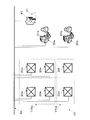
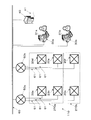
- the conceptual diagram of the air conditioning control system which concerns on 1st Embodiment of this invention The conceptual diagram of the air conditioning control system which changed the grouping of the air conditioning apparatus which concerns on 1st Embodiment of this invention.
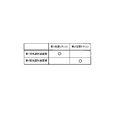
- the conceptual diagram of the definition file used with the air conditioning control system which concerns on 2nd Embodiment of this invention The conceptual diagram of the definition file used with the air conditioning control system which concerns on 3rd Embodiment of this invention.
- the conceptual diagram of the definition file used with the air conditioning control system which concerns on 4th Embodiment of this invention The conceptual diagram of the weekly schedule information used with the air conditioning control system which concerns on 5th Embodiment of this invention.
- FIG. 10 The conceptual diagram of the air conditioning control system 10 which concerns on 1st Embodiment of this invention is shown in FIG.
- the first air conditioner 20a, the second air conditioner 20b, the third air conditioner 20c, the fourth air conditioner 20d, the fifth air conditioner 20e, the sixth air conditioner 20f, A first general-purpose terminal 30a, a second general-purpose terminal 30b, and a manager terminal 40 are connected via a communication network 60.
- each element which comprises the air conditioning control system 10 is demonstrated.
- the first air conditioning apparatus 20a has air conditioning functions such as a start / stop function, a temperature control function, and an air volume control function.
- the second air conditioner 20b, the third air conditioner 20c, the fourth air conditioner 20d, the fifth air conditioner 20e, and the sixth air conditioner 20f are the same as the first air conditioner 20a.
- the first general-purpose terminal 30a has a function of displaying a user interface (hereinafter referred to as a first virtual remote controller) 31a for controlling an arbitrary air conditioner group 70a, 70b. Similar to the first general-purpose terminal 30a, the second general-purpose terminal 30b has a function of displaying the second virtual remote controller 31b.
- the air conditioner groups 70a and 70b that can be controlled from the virtual remote controllers 31a and 31b are defined by a definition file 41 described later.
- a general client personal computer is used as the general-purpose terminals 30a and 30b.
- the administrator terminal 40 includes a definition file 41 in which air conditioner groups 70a and 70b that can be controlled from the virtual remote controllers 31a and 31b are described.
- a conceptual diagram of the definition file 41 is shown in FIG. In the table of FIG. 4, circles are described in the cells indicating the air conditioner groups 70 a and 70 b that can be controlled by the users of the general-purpose terminals 30 a and 30 b from the respective virtual remote controllers 31 a and 31 b. That is, the user of the first general-purpose terminal 30a can control the first air conditioner group 70a from the first virtual remote controller 31a, and the user of the second general-purpose terminal 30b can control the second air conditioner group from the second virtual remote controller 31b. 70b can be controlled.
- the manager terminal 40 includes grouping means for the air conditioners 20a, 20b, 20c, 20d, 20e, and 20f and a user interface for the grouping means.
- the user of the administrator terminal 40 can quickly group the air conditioners 20a, 20b, 20c, 20d, 20e, and 20f into an arbitrary air conditioner group using the user interface.
- FIG. 2 is a conceptual diagram of the air conditioning control system 10 in which the grouping of the air conditioning apparatuses 20a, 20b, 20c, 20d, 20e, and 20f included in the air conditioning control system 10 according to the present embodiment is changed by the grouping unit.
- the first air conditioner 20a, the second air conditioner 20b, the fourth air conditioner 20d, and the fifth air conditioner 20e belong to the first 'air conditioner group 170a
- the third air conditioner 20c and The sixth air conditioner 20f belongs to the second 'air conditioner group 170b.
- the user of the first general-purpose terminal 30a can control the first 'air conditioner group 170a from the first virtual remote controller 31a, and the user of the second general-purpose terminal 30b can control from the second virtual remote controller 31b.
- the second ′ air conditioner group 170b can be controlled.
- the manager terminal 40 has information referred to by the definition file 41.
- the information referred to by the definition file 41 is information such as model / management number / function information of the air conditioners 20a, 20b, 20c, 20d, 20e, 20f, and network addresses of the general-purpose terminals 30a, 30b.
- the manager terminal 40 has a function of registering the general-purpose terminals 30 a and 30 b in the air conditioning control system 10.
- a general server personal computer is used as the administrator terminal 40.
- (4) Communication Network As the communication network 60, a LAN generally used in homes and companies is used.
- the user of the manager terminal 40 can quickly and flexibly change the air conditioner groups 70a and 70b that can be controlled from the virtual remote controllers 31a and 31b.
- the users of the general-purpose terminals 30a and 30b can control the air conditioner groups 70a and 70b defined in advance in the definition file 41 by using the virtual remote controllers 31a and 31b.
- the user of the manager terminal 40 can quickly group the air conditioners 20a, 20b, 20c, 20d, 20e, and 20f into an arbitrary air conditioner group. For example, in a tenant building, an air conditioner group can be set for each area to which a tenant belongs.
- ⁇ Modification> (1) In the air conditioning control system 10 according to the previous embodiment, six air conditioning apparatuses 20a, 20b, 20c, 20d, 20e, and 20f are connected via the communication network 60. An air conditioner may be connected. (2) In the air conditioning control system 10 according to the previous embodiment, the two air conditioning apparatus groups 70a and 70b are present, but an arbitrary number of air conditioning apparatus groups may be present. In addition, although three air conditioners 20a, 20b, and 20c belong to the air conditioner group 70a, any number of arbitrary air conditioners may belong to the air conditioner group. (3) In the air conditioning control system 10 according to the previous embodiment, the two general-purpose terminals 30a and 30b are connected via the communication network 60, but an arbitrary number of general-purpose terminals may be connected.
- a general client personal computer is used as the general-purpose terminals 30a and 30b, but a workstation or a mobile terminal (such as a mobile phone or a PDA) is used. It may be.
- the function of setting a password for the general-purpose terminals 30a and 30b registered in the air conditioning control system 10 is an administrator terminal. 40 may be provided. Thereby, the user of the manager terminal 40 can limit the users of the general-purpose terminals 30a and 30b.
- a general server personal computer is used as the manager terminal 40, but in a larger air conditioning control system, a main frame is used. May be.
- the manager terminal 40 has a user interface for grouping means of the air conditioning apparatuses 20a, 20b, 20c, 20d, 20e, and 20f. However, a dedicated terminal device that provides the grouping means may be connected via the communication network 60.
- the administrator terminal 40 may store the definition file 41 in a format suitable for computer processing, such as XML or a database.
- the user of the manager terminal 40 may manage the definition file 41 in a format that can be easily edited manually, such as the table shown in FIG. (9)
- a LAN is used as the communication network 60.
- it may be a network composed of lines capable of bidirectionally communicating information regardless of wired or wireless.
- WAN or VPN may be used.
- Second Embodiment ⁇ Configuration>
- an air conditioning control system in which the definition file 41 shown in FIG. 4 in the air conditioning control system 10 according to the first embodiment is replaced with the definition file shown in FIG. 5 will be described.
- the components other than the definition file are the same as those in the air conditioning control system 10 according to the first embodiment shown in FIG.
- the functions of the air conditioner groups 70a and 70b that can be used from the respective virtual remote controllers 31a and 31b are defined.
- the functions of the air conditioner groups 70a and 70b refer to a start / stop function, a temperature adjustment function, and an air volume adjustment function.
- circles are described in the cells indicating the functions of the air conditioner groups 70 a and 70 b that can be used by the users of the general-purpose terminals 30 a and 30 b from the virtual remote controllers 31 a and 31 b. That is, the user of the first general-purpose terminal 30a can use the start / stop function, the temperature adjustment function, and the air volume adjustment function of the first air conditioner group 70a from the first virtual remote controller 31a, and the second air conditioner group. The temperature control function of 70b can be used. Similarly, the user of the second general-purpose terminal 30b can use the start / stop function and the temperature control function of the first air conditioner group 70a from the second virtual remote controller 31b. The stop function and the air volume adjustment function can be used respectively.
- the priority order between the virtual remote controllers 31a and 31b for the control information for using the functions of the air conditioner groups 70a and 70b is defined.
- numerical values are described in the cells indicating the functions of the air conditioner groups 70a and 70b that can be used by the users of the general-purpose terminals 30a and 30b from the virtual remote controllers 31a and 31b, respectively.
- the numerical value represents the priority order between the virtual remote controllers 31a and 31b for the functions of the air conditioner groups 70a and 70b. The lower the numerical value, the higher the priority order.
- the contents set from one virtual remote controller 31a, 31b having a higher priority cannot be changed from other virtual remote controllers 31a, 31b having a lower priority.
- the settings from the virtual remote controllers 31a and 31b operated later in time are set. Priority is applied.
- the set temperature of the first air conditioner group 70a changed by the user of the second general-purpose terminal 30b from the second virtual remote controller 31b is changed by the user of the first general-purpose terminal 30a from the first virtual remote control 31a.
- the set temperature of the first air conditioner group 70a changed by the user of the first general-purpose terminal 30a from the first virtual remote controller 31a can be changed by the user of the second general-purpose terminal 30b from the second virtual remote control 31b. I can't.
- the set temperature of the second air conditioner group 70b changed by the user of the first general-purpose terminal 30a from the first virtual remote controller 31a can be changed by the user of the second general-purpose terminal 30b from the second virtual remote control 31b.
- the user of the first general-purpose terminal 30a can change the set temperature of the second air conditioner group 70b changed by the user of the general-purpose terminal 30b from the second virtual remote controller 31b.
- the user of the first general-purpose terminal 30a can use the air volume adjustment function of the first air conditioner group 70a from the first virtual remote controller 31a, but the user of the second general-purpose terminal 30b can The air volume adjustment function of the 1 air conditioner group 70a cannot be used.
- the user of the manager terminal 40 updates the definition file so that the virtual remote controllers 31a and 31b can function with respect to the functions of the air conditioner groups 70a and 70b that can be used from the respective virtual remote controllers 31a and 31b. Priorities can be changed quickly and flexibly.
- the users of the general-purpose terminals 30a and 30b can use the air conditioners grouped from the virtual remote controllers 31a and 31b according to the priority order between the virtual remote controllers 31a and 31b with respect to the functions of the air conditioner groups 70a and 70b defined in advance in the definition file.
- the functions 70a and 70b can be used.
- Fourth Embodiment ⁇ Configuration> As the fourth embodiment, an air conditioning control system in which the definition file 41 shown in FIG.
- the components other than the definition file are the same as those of the first embodiment shown in FIG.
- the first user ID, the second user ID, and the third user ID described in FIG. 7 are information for identifying the users of the general-purpose terminals 30a and 30b.
- the definition file shown in FIG. 7 in the present embodiment is a group of air conditioners that can be used from any virtual remote controller 31a, 31b by a user who has logged in with the first user ID, the second user ID, and the third user ID.
- the functions 70a and 70b are defined.
- the functions of the air conditioner groups 70a and 70b indicate a start / stop function, a temperature adjustment function, and an air volume adjustment function.
- circles are described in the cells indicating the functions of the air conditioner groups 70 a and 70 b that can be used by the user who has logged in with the first user ID, the second user ID, and the third user ID. Yes.
- the user who has logged in with the first user ID can use the start / stop function, the temperature adjustment function, and the air volume adjustment function of the first air conditioner group 70a from any of the virtual remote controllers 31a and 31b.
- the temperature control function of the device group 70b can be used.
- a user who has logged in with the second user ID can use the start / stop function and the temperature control function of the first air conditioner group 70a from any of the virtual remote controllers 31a and 31b, and the second air conditioner group 70b.
- the start / stop function and the temperature control function can be used.
- the user who has logged in with the third user ID can use the start / stop function, the temperature adjustment function, and the air volume adjustment function of the second air conditioner group 70b from any of the virtual remote controllers 31a and 31b.
- the user of the administrator terminal 40 uses the definition file shown in FIG. 7 so that a user who has logged in with the first user ID, the second user ID, and the third user ID can use from any virtual remote controller 31a, 31b.
- the functions of the air conditioner groups 70a and 70b that can be changed can be quickly and flexibly changed. For this reason, even when a user who has logged in with the first user ID, the second user ID, and the third user ID uses any general-purpose terminals 30a and 30b, the functions of the air conditioner groups 70a and 70b that can be used are as follows. Not changed.
- an air conditioning apparatus that can be used by a user who has logged in with the first user ID, the second user ID, and the third user ID from any virtual remote controller 31a, 31b.
- the functions of the groups 70a and 70b are defined in the definition file, the login is performed with the first user ID, the second user ID, and the third user ID according to the definition file 41 shown in FIG. 4 in the first embodiment.
- the air conditioning apparatus groups 70a and 70b that can be controlled by the user from any of the virtual remote controllers 31a and 31b may be defined in the definition file.
- an air conditioning apparatus that can be used from any virtual remote controller 31a, 31b by a user who has logged in with the first user ID, the second user ID, and the third user ID.
- the functions of the groups 70a and 70b are defined in the definition file
- the first user ID and the second user ID for the functions of the air conditioner groups 70a and 70b are copied in accordance with the definition file shown in FIG. 6 in the third embodiment.
- the priority order between the user ID and the third user ID may be defined in the definition file.
- Fifth embodiment ⁇ Configuration>
- an air conditioning control system including a manager terminal 40 that automatically changes a definition file based on schedule information is given.
- the user of the manager terminal 40 uses the definition file as the time. It is necessary to correct and change manually according to the belt.
- the manager terminal 40 has weekly schedule information shown in FIG. The manager terminal 40 automatically adapts the definition file specified in the specified time zone to the air conditioning control system according to the weekly schedule information.
- definition files are set for each of the four time zones on each day of the week.
- the four time zones are the first non-working hours from 0:00 to 8:00, the working hours from 8:00 to 17:00, the overtime hours from 17:00 to 21:00, and the hours from 21:00 to 24:00 It is the second non-working time zone.
- the administrator terminal 40 has a definition file A for weekday working hours, a definition file B for weekday overtime hours, and a definition file for weekday first non-working hours and second non-working hours and holidays.
- Adapt C to the air conditioning control system.
- the definition file A, the definition file B, and the definition file C are definition files for realizing an air conditioning control system suitable for each time zone.
- the functions of the air conditioner groups 70a and 70b that can be used from the virtual remote controllers 31a and 31b are limited compared to the definition file A and the definition file B.
- the user of the manager terminal 40 can use the functions of the air conditioner groups 70a and 70b that can be used from the virtual remote controllers 31a and 31b.
- a more limited air conditioning control system can be constructed.
- an air conditioning control system capable of thoroughly implementing energy saving operation can be constructed.
- the manager terminal 40 has weekly schedule information shown in FIG. 8, but may have annual schedule information. Thereby, for example, the user of the manager terminal 40 automatically changes the settable temperature range of the air conditioner groups 70a and 70b that can be controlled from the virtual remote controllers 31a and 31b according to the season.
- a harmonic control system can be constructed.
- an air conditioning control system including a manager terminal 40 that automatically changes a definition file due to an external factor will be described.
- external factors include environmental factors such as the amount of change in outside air temperature, external triggers such as turning on / off indoor lighting switches, demand control, and the like.
- an air conditioning control system using an example of an external factor will be described. First, consider an air conditioning control system including an administrator terminal 40 that changes a definition file according to a measured value of an outside air temperature acquired from an outside air temperature measuring device installed outdoors.
- the manager terminal 40 uses the temperature adjustment function of the air conditioner groups 70a and 70b from the virtual remote controllers 31a and 31b.
- the definition file that prohibits is automatically applied.
- achieves automatically the energy saving operation by an outside air cooling effect can be constructed
- an air conditioning control system including an administrator terminal 40 that changes a definition file in conjunction with opening and closing of a lighting switch.
- the administrator terminal 40 detects an area where the lighting switch is turned off, and a definition file that prohibits the use of the temperature control function of the air conditioner groups 70a and 70b existing in the area by the virtual remote controllers 31a and 31b. Automatically adapt.
- an air conditioning control system that automatically realizes energy saving operation of the air conditioning devices 20a, 20b, 20c, 20d, 20e, and 20f belonging to the air conditioning device groups 70a and 70b existing in the unattended area. it can.
- an air-conditioning control system linked to a demand control system.
- the demand control system is an air conditioner.
- the operation of 20a, 20b, 20c, 20d, 20e, and 20f is limited for a predetermined time.
- the administrator terminal 40 receives a notification restricting the operation of the air conditioners 20a, 20b, 20c, 20d, 20e, and 20f from the demand control system, and then receives the air conditioner groups 70a and 70b from the virtual remote controllers 31a and 31b. Automatically apply definition files that restrict control of Thereby, the air conditioning control system which can implement
- FIG. 3 The conceptual diagram of the air conditioning control system 110 which concerns on 7th Embodiment of this invention is shown in FIG. 3, elements having the same reference numerals as those in FIG. 1 are the same as elements having the corresponding reference numerals in FIG.
- the first general-purpose terminal 30a, the second general-purpose terminal 30b, the manager terminal 40, the first central control device 50a, and the second central control device 50b are connected via the communication network 60.
- the first central control device 50a is connected to the first air conditioner 20a, the second air conditioner 20b, and the third air conditioner 20c via the communication line 61
- the second central control device 50b is connected via the communication line 61.
- the fourth air conditioner 20d, the fifth air conditioner 20e, and the sixth air conditioner 20f are connected.
- the first air conditioner 20a, the second air conditioner 20b, the fourth air conditioner 20d, and the fifth air conditioner 20e belong to the first “air conditioner group 270a
- the third air conditioner 20c and The sixth air conditioner 20f belongs to the second “air conditioner group 270b”.
- the centralized control devices 50a and 50b include the model / management number / function information of the air conditioners 20a, 20b, 20c, 20d, 20e, and 20f, and the network addresses of the general-purpose terminals 30a and 30b. Is held by automatic communication or manual input.
- the central control devices 50a and 50b receive the control information of the air conditioners 20a, 20b, 20c, 20d, 20e, and 20f transmitted from the general-purpose terminals 30a and 30b, and the appropriate air conditioners 20a and 20b under the umbrella are received. It has a function of automatically transmitting control information to 20b, 20c, 20d, 20e, and 20f.
- the central control devices 50a and 50b have a function of monitoring the status of the air conditioners 20a, 20b, 20c, 20d, 20e, and 20f under the umbrella and notifying the general-purpose terminals 30a and 30b. For example, when a new air conditioner is added to the air conditioning control system 110 or when an existing air conditioning apparatus is removed, the central control devices 50a and 50b are the air that the air conditioning control system 110 currently has. Automatically recognizes the harmony device.
- a dedicated line is used as the communication line 61.
- the administrator of the air conditioning control system 110 can manage the air conditioning devices efficiently by using the centralized control devices 50a and 50b.
- a dedicated line is used as the communication line 61.
- a LAN cable or An optical cable or the like may be used.
- the central control devices 50a and 50b automatically transmit control information to the appropriate air conditioning devices 20a, 20b, 20c, 20d, 20e, and 20f.
- the function of centrally controlling the air conditioners 20a, 20b, 20c, 20d, 20e, and 20f is, for example, the function of the central controller 50a prohibiting the air conditioners 20a, 20b, and 20c from setting temperature for energy saving. And a function to set upper and lower temperature limits for comfort control.
- the definition file needs to describe the association between the function of centrally controlling the air conditioners 20a, 20b, 20c, 20d, 20e, and 20f of the central control devices 50a and 50b and the virtual remote controllers 31a and 31b. is there.
- the administrator of the air conditioning control system can change the air conditioning control information quickly and flexibly using the manager terminal. Therefore, the air conditioning control system according to the present invention can be used as an efficient air conditioning control system for a large-scale space where a large number of air conditioning apparatuses are installed.
Landscapes
- Engineering & Computer Science (AREA)
- Chemical & Material Sciences (AREA)
- Combustion & Propulsion (AREA)
- Mechanical Engineering (AREA)
- General Engineering & Computer Science (AREA)
- Human Computer Interaction (AREA)
- Air Conditioning Control Device (AREA)
Abstract
本発明の課題は、任意のグループに属する空気調和装置をパソコンなどの汎用端末からネットワークを介して一括して制御することができる空気調和制御システムであって、グループに属する空気調和装置を汎用端末から一括して制御するための設定を、迅速かつ柔軟に変更することができる空気調和制御システムを提供することにある。 本発明に係る空気調和制御システム10は、空気調和装置群70a,70bと、空気調和装置群70a,70bに属する空気調和装置20a,20b,20c,20d,20e,20fを群単位で制御するためのユーザインターフェイス31a,31bを表示する汎用端末30a,30bと、汎用端末30a,30bのユーザインターフェイス31a,31bから制御可能な空気調和装置群70a,70bを定義する定義ファイル41を有する管理者用端末40と、通信網60と、を備える。
Description
この発明は、汎用端末を用いて空気調和装置を制御するための空気調和制御システムに関する。
現在、ネットワークを介してパソコンなどの汎用端末から空気調和装置の運転制御をする技術が提案されている。
例えば、特許文献1(特開2002-071198号公報)に開示されているブラウザ利用空調制御システムでは、システムの管理者は、インターネットを介してパソコン上のブラウザから空気調和装置を遠隔操作・遠隔監視することができる。
また、ネットワークに接続された複数台の空気調和装置を任意にグループ化して、グループに属する空気調和装置を専用の集中制御機器により一括して制御する技術が提案されている。
例えば、特許文献2(特開2001-235217号公報)に開示されている空気調和装置の制御装置では、複数の系統(ゾーン)に属する複数台の空気調和装置が同一通信線上に接続されたシステムにおいて、系統(ゾーン)を越えて任意にグループ化された空気調和装置を、一台の集中制御管理機器を用いて一括して制御することができる。
例えば、特許文献1(特開2002-071198号公報)に開示されているブラウザ利用空調制御システムでは、システムの管理者は、インターネットを介してパソコン上のブラウザから空気調和装置を遠隔操作・遠隔監視することができる。
また、ネットワークに接続された複数台の空気調和装置を任意にグループ化して、グループに属する空気調和装置を専用の集中制御機器により一括して制御する技術が提案されている。
例えば、特許文献2(特開2001-235217号公報)に開示されている空気調和装置の制御装置では、複数の系統(ゾーン)に属する複数台の空気調和装置が同一通信線上に接続されたシステムにおいて、系統(ゾーン)を越えて任意にグループ化された空気調和装置を、一台の集中制御管理機器を用いて一括して制御することができる。
ところで、ネットワークに接続された複数台の空気調和装置を任意にグループ化して、グループに属する空気調和装置をパソコンなどの汎用端末上のユーザインターフェイスから一括して制御することができるシステムを構築しようとする際に、空気調和装置と汎用端末との関連付けの設定を、個々の空気調和装置及び汎用端末に対して行うと煩雑で時間もかかる。
そこで、本発明の目的は、ネットワークを介して任意のグループに属する空気調和装置をパソコンなどの汎用端末から一括して制御することができる空気調和制御システムであって、グループに属する空気調和装置を汎用端末から一括して制御するための設定を、迅速かつ柔軟に変更することができる空気調和制御システムを提供することにある。
そこで、本発明の目的は、ネットワークを介して任意のグループに属する空気調和装置をパソコンなどの汎用端末から一括して制御することができる空気調和制御システムであって、グループに属する空気調和装置を汎用端末から一括して制御するための設定を、迅速かつ柔軟に変更することができる空気調和制御システムを提供することにある。
第1発明に係る空気調和制御システムは、複数台の空気調和装置と、グループ化手段と、複数台の汎用端末と、管理者用端末とを備えている。グループ化手段は、空気調和装置を任意にグループ分けして空気調和装置群を生成する。汎用端末は、通信網を介して空気調和装置と接続され、グループ化手段により生成された空気調和装置群を制御することができるユーザインターフェイス(以下、仮想リモコンという。)を有している。ここで、「空気調和装置群を制御する」こととは、「空気調和装置群に属する全ての空気調和装置を一括して制御する」ことを意味する(以下同様)。管理者用端末は、通信網を介して汎用端末と接続され、汎用端末の仮想リモコンから制御することができる空気調和装置群の制御に関する情報(以下、空調制御情報という。)が記述されている定義ファイルを有している。
本発明によれば、当該空気調和制御システムが備える汎用端末のユーザは、汎用端末の仮想リモコンから任意の空気調和装置群を制御することができる。また、空調制御情報は、各汎用端末によって管理される代わりに、管理者用端末が有している定義ファイルに記述されている。そのため、当該空気調和制御システムの管理者は、管理者用端末を用いて空調制御情報を迅速かつ柔軟に変更することができる。また、当該空気調和制御システムの管理者は、管理者用端末を用いて空調制御情報を汎用端末のユーザに隠蔽して一元的に管理することができる。
第2発明に係る空気調和制御システムは、第1発明に係る空気調和制御システムであって、定義ファイルには、汎用端末の仮想リモコンから制御することができる空気調和装置群に関する情報が記述されている。
本発明によれば、汎用端末のユーザが仮想リモコンを用いて任意の空気調和装置群を制御することができるか否かに関する情報が、定義ファイルに記述されている。そのため、例えば、空気調和制御システムの管理者は管理者用端末を用いて迅速かつ柔軟に、一の汎用端末の仮想リモコンによる任意の空気調和装置群の制御を許可することができ、別の汎用端末の仮想リモコンによる当該空気調和装置群の制御を禁止することができる。
本発明によれば、汎用端末のユーザが仮想リモコンを用いて任意の空気調和装置群を制御することができるか否かに関する情報が、定義ファイルに記述されている。そのため、例えば、空気調和制御システムの管理者は管理者用端末を用いて迅速かつ柔軟に、一の汎用端末の仮想リモコンによる任意の空気調和装置群の制御を許可することができ、別の汎用端末の仮想リモコンによる当該空気調和装置群の制御を禁止することができる。
第3発明に係る空気調和制御システムは、第1発明または第2発明に係る空気調和制御システムであって、定義ファイルには、汎用端末の仮想リモコンから使用することができる空気調和装置群の機能に関する情報が記述されている。ここで、「空気調和装置群の機能」とは「空気調和装置群に属する全ての空気調和装置が共通して有する機能」を意味し、「空気調和装置群の機能を使用する」こととは、「空気調和装置群に属する全ての空気調和装置が共通して有する一の機能を、当該全ての空気調和装置に対して使用する」ことを意味する(以下同様)。空気調和装置群の機能とは、例えば、空気調和装置の発停機能、温度調節機能及び風量調節機能を指す。
本発明によれば、汎用端末のユーザが仮想リモコンを用いて任意の空気調和装置群の機能を使用することができるか否かに関する情報が、定義ファイルに記述されている。そのため、例えば、空気調和制御システムの管理者は管理者用端末を用いて迅速かつ柔軟に、一の汎用端末の仮想リモコンによる任意の空気調和装置群の温度調節機能の使用を許可することができ、別の汎用端末の仮想リモコンによる当該空気調和装置群の温度調節機能の使用を禁止することができる。
第4発明に係る空気調和制御システムは、第1発明から第3発明のいずれかに係る空気調和制御システムであって、定義ファイルには、一の空気調和装置群に対して複数台の汎用端末から送信される複数の制御情報に対する当該汎用端末間の優先順位が記述されている。
本発明によれば、一の空気調和装置群に属する空気調和装置に対して制御情報を送信する汎用端末が複数台存在する場合に、当該制御情報に対する汎用端末間の優先順位が、定義ファイルに記述されている。そのため、例えば、本発明に係る空気調和制御システムは、一の汎用端末から任意の空気調和装置群に属する空気調和装置に対して送信された制御情報を、他の汎用端末から当該空気調和装置群に属する空気調和装置に対して送信された制御情報より優先的に処理することができる。
本発明によれば、一の空気調和装置群に属する空気調和装置に対して制御情報を送信する汎用端末が複数台存在する場合に、当該制御情報に対する汎用端末間の優先順位が、定義ファイルに記述されている。そのため、例えば、本発明に係る空気調和制御システムは、一の汎用端末から任意の空気調和装置群に属する空気調和装置に対して送信された制御情報を、他の汎用端末から当該空気調和装置群に属する空気調和装置に対して送信された制御情報より優先的に処理することができる。
第5発明に係る空気調和制御システムは、第1発明から第4発明のいずれかに係る空気調和制御システムであって、管理者用端末は、グループ化手段及び当該グループ化手段のためのユーザインターフェイスを有している。
本発明によれば、複数台の空気調和装置を任意にグループ分けして空気調和装置群を生成するグループ化手段と、当該グループ化手段を実現するためのユーザインターフェイスを、管理者用端末が有している。管理者用端末のユーザは、当該ユーザインターフェイスを用いて空気調和装置群を迅速に生成及び変更することができる。そのため、例えば、空気調和制御システムの管理者は管理者用端末を用いて、多数の空気調和装置を備えているテナントビルにおいて、空気調和装置を各テナントが属するエリアごとにグループ分けして管理している場合に、テナントが属するエリアの変更に伴う空気調和装置のグループ分けを迅速に行うことができる。
本発明によれば、複数台の空気調和装置を任意にグループ分けして空気調和装置群を生成するグループ化手段と、当該グループ化手段を実現するためのユーザインターフェイスを、管理者用端末が有している。管理者用端末のユーザは、当該ユーザインターフェイスを用いて空気調和装置群を迅速に生成及び変更することができる。そのため、例えば、空気調和制御システムの管理者は管理者用端末を用いて、多数の空気調和装置を備えているテナントビルにおいて、空気調和装置を各テナントが属するエリアごとにグループ分けして管理している場合に、テナントが属するエリアの変更に伴う空気調和装置のグループ分けを迅速に行うことができる。
第6発明に係る空気調和制御システムは、第1発明から第5発明のいずれかに係る空気調和制御システムであって、管理者用端末は、管理者用端末に入力されたスケジュール情報に従って定義ファイルの内容を変更する。
本発明によれば、当該スケジュール情報に従って、指定された時間に定義ファイルの内容を自動的に変更する管理者用端末を備える空気調和制御システムを構築することができる。そのため、例えば、空気調和制御システムの管理者は管理者用端末を用いて、就業時間外に汎用端末からの任意の空気調和装置群の制御を禁止することができる。
本発明によれば、当該スケジュール情報に従って、指定された時間に定義ファイルの内容を自動的に変更する管理者用端末を備える空気調和制御システムを構築することができる。そのため、例えば、空気調和制御システムの管理者は管理者用端末を用いて、就業時間外に汎用端末からの任意の空気調和装置群の制御を禁止することができる。
第7発明に係る空気調和制御システムは、第1発明から第6発明のいずれかに係る空気調和制御システムであって、専用の集中制御装置をさらに備えている。当該集中制御装置は、通信回線を介して空気調和装置と接続されるとともに、通信網を介して汎用端末と接続される。また、当該集中制御装置は、空気調和装置又は汎用端末から送信される制御情報を空気調和装置又は汎用端末との間で双方向に送受信する。
本発明によれば、汎用端末が集中制御機器に対して制御情報を送信すると、当該集中制御機器は適切な空気調和装置群に属する空気調和装置に対して制御情報を自動的に送信することができる。そのため、汎用端末から送信される制御情報の処理の効率性を向上させることができる。
本発明によれば、汎用端末が集中制御機器に対して制御情報を送信すると、当該集中制御機器は適切な空気調和装置群に属する空気調和装置に対して制御情報を自動的に送信することができる。そのため、汎用端末から送信される制御情報の処理の効率性を向上させることができる。
第8発明に係る空気調和制御システムは、第1発明から第7発明のいずれかに係る空気調和制御システムであって、定義ファイルを解釈して汎用端末の仮想リモコンに空気調和装置群を制御する機能を割り当てるプログラム(以下、空気調和制御プログラムという。)を有する管理者用端末を備えている。
本発明によれば、当該空気調和制御システムを運用する上で基幹となる機能は、管理者用端末が有する空気調和制御プログラムによって実現されるので、空気調和制御システムの保守性を向上させることができる。
本発明によれば、当該空気調和制御システムを運用する上で基幹となる機能は、管理者用端末が有する空気調和制御プログラムによって実現されるので、空気調和制御システムの保守性を向上させることができる。
第1発明に係る空気調和制御システムでは、空気調和制御システムの管理者は管理者用端末を用いて、汎用端末の仮想リモコンから制御することができる空気調和装置群の制御に関する情報を迅速かつ柔軟に変更することができる。
第2発明に係る空気調和制御システムでは、空気調和制御システムの管理者は管理者用端末を用いて迅速かつ柔軟に、一の汎用端末の仮想リモコンによる任意の空気調和装置群の制御を許可することができ、別の汎用端末の仮想リモコンによる当該空気調和装置群の制御を禁止することができる。
第3発明に係る空気調和制御システムでは、空気調和制御システムの管理者は管理者用端末を用いて迅速かつ柔軟に、一の汎用端末の仮想リモコンによる任意の空気調和装置群の温度調節機能の使用を許可することができ、別の汎用端末の仮想リモコンによる当該空気調和装置群の温度調節機能の使用を禁止することができる。
第4発明に係る空気調和制御システムでは、一の汎用端末から任意の空気調和装置群に属する空気調和装置に対して送信された制御情報を、他の汎用端末から当該空気調和装置群に属する空気調和装置に対して送信された制御情報より優先的に処理することができる。
第2発明に係る空気調和制御システムでは、空気調和制御システムの管理者は管理者用端末を用いて迅速かつ柔軟に、一の汎用端末の仮想リモコンによる任意の空気調和装置群の制御を許可することができ、別の汎用端末の仮想リモコンによる当該空気調和装置群の制御を禁止することができる。
第3発明に係る空気調和制御システムでは、空気調和制御システムの管理者は管理者用端末を用いて迅速かつ柔軟に、一の汎用端末の仮想リモコンによる任意の空気調和装置群の温度調節機能の使用を許可することができ、別の汎用端末の仮想リモコンによる当該空気調和装置群の温度調節機能の使用を禁止することができる。
第4発明に係る空気調和制御システムでは、一の汎用端末から任意の空気調和装置群に属する空気調和装置に対して送信された制御情報を、他の汎用端末から当該空気調和装置群に属する空気調和装置に対して送信された制御情報より優先的に処理することができる。
第5発明に係る空気調和制御システムでは、空気調和制御システムの管理者は管理者用端末を用いて、多数の空気調和装置を備えているテナントビルにおいて、空気調和装置を各テナントが属するエリアごとにグループ分けして管理している場合に、テナントが属するエリアの変更に伴う空気調和装置のグループ分けを迅速に行うことができる。
第6発明に係る空気調和制御システムでは、空気調和制御システムの管理者は管理者用端末を用いて、就業時間外に汎用端末からの任意の空気調和装置群の制御を禁止することができる。
第7発明に係る空気調和制御システムでは、汎用端末から送信される制御情報の処理の効率性を向上させることができる。
第8発明に係る空気調和制御システムでは、空気調和制御システムの保守性を向上させることができる。
第6発明に係る空気調和制御システムでは、空気調和制御システムの管理者は管理者用端末を用いて、就業時間外に汎用端末からの任意の空気調和装置群の制御を禁止することができる。
第7発明に係る空気調和制御システムでは、汎用端末から送信される制御情報の処理の効率性を向上させることができる。
第8発明に係る空気調和制御システムでは、空気調和制御システムの保守性を向上させることができる。
=第1実施形態=
<構成>
本発明の第1実施形態に係る空気調和制御システム10の概念図を図1に示す。空気調和制御システム10では、第1空気調和装置20a、第2空気調和装置20b、第3空気調和装置20c、第4空気調和装置20d、第5空気調和装置20e、第6空気調和装置20f、第1汎用端末30a、第2汎用端末30b及び管理者用端末40が通信網60を介して接続されている。
以下、空気調和制御システム10を構成している各要素について説明する。
(1)空気調和装置
第1空気調和装置20aは、発停機能、温度調節機能及び風量調節機能などの空気調和機能を有する。第2空気調和装置20b、第3空気調和装置20c、第4空気調和装置20d、第5空気調和装置20e及び第6空気調和装置20fも、第1空気調和装置20aと同様である。
<構成>
本発明の第1実施形態に係る空気調和制御システム10の概念図を図1に示す。空気調和制御システム10では、第1空気調和装置20a、第2空気調和装置20b、第3空気調和装置20c、第4空気調和装置20d、第5空気調和装置20e、第6空気調和装置20f、第1汎用端末30a、第2汎用端末30b及び管理者用端末40が通信網60を介して接続されている。
以下、空気調和制御システム10を構成している各要素について説明する。
(1)空気調和装置
第1空気調和装置20aは、発停機能、温度調節機能及び風量調節機能などの空気調和機能を有する。第2空気調和装置20b、第3空気調和装置20c、第4空気調和装置20d、第5空気調和装置20e及び第6空気調和装置20fも、第1空気調和装置20aと同様である。
また、後述する管理者用端末40が有するグループ化手段により、第1空気調和装置20a、第2空気調和装置20b及び第3空気調和装置20cは第1空気調和装置群70aに属し、第4空気調和装置20d、第5空気調和装置20e及び第6空気調和装置20fは第2空気調和装置群70bに属している。
(2)汎用端末
第1汎用端末30aは、任意の空気調和装置群70a,70bを制御するためのユーザインターフェイス(以下、第1仮想リモコンという。)31aを表示する機能を有する。第1汎用端末30aと同様に、第2汎用端末30bは第2仮想リモコン31bを表示する機能を有する。仮想リモコン31a,31bから制御することができる空気調和装置群70a,70bは、後述する定義ファイル41によって定義されている。汎用端末30a,30bとしては、一般的なクライアント用パソコンが用いられる。
(2)汎用端末
第1汎用端末30aは、任意の空気調和装置群70a,70bを制御するためのユーザインターフェイス(以下、第1仮想リモコンという。)31aを表示する機能を有する。第1汎用端末30aと同様に、第2汎用端末30bは第2仮想リモコン31bを表示する機能を有する。仮想リモコン31a,31bから制御することができる空気調和装置群70a,70bは、後述する定義ファイル41によって定義されている。汎用端末30a,30bとしては、一般的なクライアント用パソコンが用いられる。
(3)管理者用端末
管理者用端末40は、仮想リモコン31a,31bから制御することができる空気調和装置群70a,70bが記述されている定義ファイル41を有する。定義ファイル41の概念図を図4に示す。
図4の表において、汎用端末30a,30bのユーザがそれぞれの仮想リモコン31a,31bから制御することができる空気調和装置群70a,70bを示す升目には丸印が記述されている。すなわち、第1汎用端末30aのユーザは第1仮想リモコン31aから第1空気調和装置群70aを制御することができ、第2汎用端末30bのユーザは第2仮想リモコン31bから第2空気調和装置群70bを制御することができる。
また、管理者用端末40は、空気調和装置20a,20b,20c,20d,20e,20fのグループ化手段及び当該グループ化手段のためのユーザインターフェイスを有する。管理者用端末40のユーザは、当該ユーザインターフェイスを用いて、空気調和装置20a,20b,20c,20d,20e,20fを任意の空気調和装置群に迅速にグループ分けすることができる。
管理者用端末40は、仮想リモコン31a,31bから制御することができる空気調和装置群70a,70bが記述されている定義ファイル41を有する。定義ファイル41の概念図を図4に示す。
図4の表において、汎用端末30a,30bのユーザがそれぞれの仮想リモコン31a,31bから制御することができる空気調和装置群70a,70bを示す升目には丸印が記述されている。すなわち、第1汎用端末30aのユーザは第1仮想リモコン31aから第1空気調和装置群70aを制御することができ、第2汎用端末30bのユーザは第2仮想リモコン31bから第2空気調和装置群70bを制御することができる。
また、管理者用端末40は、空気調和装置20a,20b,20c,20d,20e,20fのグループ化手段及び当該グループ化手段のためのユーザインターフェイスを有する。管理者用端末40のユーザは、当該ユーザインターフェイスを用いて、空気調和装置20a,20b,20c,20d,20e,20fを任意の空気調和装置群に迅速にグループ分けすることができる。
例えば、本実施形態に係る空気調和制御システム10が備える空気調和装置20a,20b,20c,20d,20e,20fのグループ分けを当該グループ化手段により変更した空気調和制御システム10の概念図を図2に示す。
図2において、第1空気調和装置20a、第2空気調和装置20b、第4空気調和装置20d及び第5空気調和装置20eは第1'空気調和装置群170aに属し、第3空気調和装置20c及び第6空気調和装置20fは第2'空気調和装置群170bに属している。空気調和制御システム10において、第1汎用端末30aのユーザは第1仮想リモコン31aから第1'空気調和装置群170aを制御することができ、第2汎用端末30bのユーザは第2仮想リモコン31bから第2'空気調和装置群170bを制御することができる。
図2において、第1空気調和装置20a、第2空気調和装置20b、第4空気調和装置20d及び第5空気調和装置20eは第1'空気調和装置群170aに属し、第3空気調和装置20c及び第6空気調和装置20fは第2'空気調和装置群170bに属している。空気調和制御システム10において、第1汎用端末30aのユーザは第1仮想リモコン31aから第1'空気調和装置群170aを制御することができ、第2汎用端末30bのユーザは第2仮想リモコン31bから第2'空気調和装置群170bを制御することができる。
さらに、管理者用端末40は、定義ファイル41によって参照される情報を有する。定義ファイル41によって参照される情報とは、空気調和装置20a,20b,20c,20d,20e,20fの機種・管理番号・機能の情報や汎用端末30a,30bのネットワークアドレスなどの情報である。また、管理者用端末40は汎用端末30a,30bを空気調和制御システム10に登録する機能を有する。管理者用端末40としては、一般的なサーバ用パソコンが用いられる。
(4)通信網
通信網60としては、家庭内・企業内で一般的に使用されるLANが用いられる。
(4)通信網
通信網60としては、家庭内・企業内で一般的に使用されるLANが用いられる。
<特徴>
(1)管理者用端末40のユーザは、定義ファイル41を更新することで、仮想リモコン31a,31bから制御することができる空気調和装置群70a,70bを迅速かつ柔軟に変更することができる。
(2)汎用端末30a,30bのユーザは、仮想リモコン31a,31bを用いることで、あらかじめ定義ファイル41で定義された空気調和装置群70a,70bを制御することができる。
(3)管理者用端末40のユーザは、空気調和装置20a,20b,20c,20d,20e,20fを任意の空気調和装置群に迅速にグループ分けすることができる。例えば、テナントビルにおいて、テナントが属するエリアごとに空気調和装置群を設定することができる。
(1)管理者用端末40のユーザは、定義ファイル41を更新することで、仮想リモコン31a,31bから制御することができる空気調和装置群70a,70bを迅速かつ柔軟に変更することができる。
(2)汎用端末30a,30bのユーザは、仮想リモコン31a,31bを用いることで、あらかじめ定義ファイル41で定義された空気調和装置群70a,70bを制御することができる。
(3)管理者用端末40のユーザは、空気調和装置20a,20b,20c,20d,20e,20fを任意の空気調和装置群に迅速にグループ分けすることができる。例えば、テナントビルにおいて、テナントが属するエリアごとに空気調和装置群を設定することができる。
<変形例>
(1)先の実施形態に係る空気調和制御システム10では、6台の空気調和装置20a,20b,20c,20d,20e,20fが通信網60を介して接続されているが、任意の台数の空気調和装置が接続されていてもよい。
(2)先の実施形態に係る空気調和制御システム10では、2組の空気調和装置群70a,70bが存在しているが、任意の数の空気調和装置群が存在していてもよい。また、空気調和装置群70aには3台の空気調和装置20a,20b,20cが属しているが、空気調和装置群には任意の台数の任意の空気調和装置が属していてもよい。
(3)先の実施形態に係る空気調和制御システム10では、2台の汎用端末30a,30bが通信網60を介して接続されているが、任意の台数の汎用端末が接続されていてもよい。
(4)先の実施形態に係る空気調和制御システム10では、汎用端末30a,30bとして一般的なクライアント用パソコンが用いられているが、ワークステーションや携帯端末(携帯電話・PDAなど)が用いられていてもよい。
(1)先の実施形態に係る空気調和制御システム10では、6台の空気調和装置20a,20b,20c,20d,20e,20fが通信網60を介して接続されているが、任意の台数の空気調和装置が接続されていてもよい。
(2)先の実施形態に係る空気調和制御システム10では、2組の空気調和装置群70a,70bが存在しているが、任意の数の空気調和装置群が存在していてもよい。また、空気調和装置群70aには3台の空気調和装置20a,20b,20cが属しているが、空気調和装置群には任意の台数の任意の空気調和装置が属していてもよい。
(3)先の実施形態に係る空気調和制御システム10では、2台の汎用端末30a,30bが通信網60を介して接続されているが、任意の台数の汎用端末が接続されていてもよい。
(4)先の実施形態に係る空気調和制御システム10では、汎用端末30a,30bとして一般的なクライアント用パソコンが用いられているが、ワークステーションや携帯端末(携帯電話・PDAなど)が用いられていてもよい。
(5)先の実施形態に係る空気調和制御システム10では、特に言及しなかったが、空気調和制御システム10に登録された汎用端末30a,30bに対してパスワードを設定する機能が管理者用端末40に設けられていてもよい。これにより、管理者用端末40のユーザは汎用端末30a,30bのユーザを制限することができる。
(6)先の実施形態に係る空気調和制御システム10では、管理者用端末40として一般的なサーバ用パソコンが用いられているが、より大規模な空気調和制御システムではメインフレームが用いられていてもよい。
(7)先の実施形態に係る空気調和制御システム10では、管理者用端末40が空気調和装置20a,20b,20c,20d,20e,20fのグループ化手段のためのユーザインターフェイスを有しているが、当該グループ化手段を提供する専用の端末装置が通信網60を介して接続されていてもよい。
(6)先の実施形態に係る空気調和制御システム10では、管理者用端末40として一般的なサーバ用パソコンが用いられているが、より大規模な空気調和制御システムではメインフレームが用いられていてもよい。
(7)先の実施形態に係る空気調和制御システム10では、管理者用端末40が空気調和装置20a,20b,20c,20d,20e,20fのグループ化手段のためのユーザインターフェイスを有しているが、当該グループ化手段を提供する専用の端末装置が通信網60を介して接続されていてもよい。
(8)先の実施形態に係る空気調和制御システム10では、特に言及しなかったが、管理者用端末40はXMLやデータベースなどコンピュータ処理に適した形式で定義ファイル41を記憶してもよい。また、管理者用端末40のユーザは、図4で示される表のような、手作業による編集が容易な形式で定義ファイル41を管理してもよい。
(9)先の実施形態に係る空気調和制御システム10では、通信網60としてLANが用いられているが、有線・無線を問わず情報を双方向に通信可能な回線から構成されるネットワークであれば、WANやVPNなどが用いられていてもよい。
(9)先の実施形態に係る空気調和制御システム10では、通信網60としてLANが用いられているが、有線・無線を問わず情報を双方向に通信可能な回線から構成されるネットワークであれば、WANやVPNなどが用いられていてもよい。
=第2実施形態=
<構成>
第2実施形態として、第1実施形態に係る空気調和制御システム10における図4で示された定義ファイル41を図5で示される定義ファイルに置き換えた空気調和制御システムについて記載する。本実施形態において、定義ファイル以外の構成要素は図1で示された第1実施形態に係る空気調和制御システム10と同一である。
本実施形態における図5で示された定義ファイルでは、それぞれの仮想リモコン31a,31bから使用することができる空気調和装置群70a,70bの機能が定義されている。空気調和装置群70a,70bの機能とは、発停機能、温度調節機能及び風量調節機能を指す。
図5の表において、汎用端末30a,30bのユーザがそれぞれの仮想リモコン31a,31bから使用することができる空気調和装置群70a,70bの機能を示す升目には丸印が記述されている。すなわち、第1汎用端末30aのユーザは第1仮想リモコン31aから、第1空気調和装置群70aの発停機能、温度調節機能及び風量調節機能をそれぞれ使用することができ、第2空気調和装置群70bの温度調節機能を使用することができる。同様に、第2汎用端末30bのユーザは第2仮想リモコン31bから、第1空気調和装置群70aの発停機能及び温度調節機能をそれぞれ使用することができ、第2空気調和装置群70bの発停機能及び風量調節機能をそれぞれ使用することができる。
<構成>
第2実施形態として、第1実施形態に係る空気調和制御システム10における図4で示された定義ファイル41を図5で示される定義ファイルに置き換えた空気調和制御システムについて記載する。本実施形態において、定義ファイル以外の構成要素は図1で示された第1実施形態に係る空気調和制御システム10と同一である。
本実施形態における図5で示された定義ファイルでは、それぞれの仮想リモコン31a,31bから使用することができる空気調和装置群70a,70bの機能が定義されている。空気調和装置群70a,70bの機能とは、発停機能、温度調節機能及び風量調節機能を指す。
図5の表において、汎用端末30a,30bのユーザがそれぞれの仮想リモコン31a,31bから使用することができる空気調和装置群70a,70bの機能を示す升目には丸印が記述されている。すなわち、第1汎用端末30aのユーザは第1仮想リモコン31aから、第1空気調和装置群70aの発停機能、温度調節機能及び風量調節機能をそれぞれ使用することができ、第2空気調和装置群70bの温度調節機能を使用することができる。同様に、第2汎用端末30bのユーザは第2仮想リモコン31bから、第1空気調和装置群70aの発停機能及び温度調節機能をそれぞれ使用することができ、第2空気調和装置群70bの発停機能及び風量調節機能をそれぞれ使用することができる。
<特徴>
(1)管理者用端末40のユーザは、定義ファイルを更新することで、それぞれの仮想リモコン31a,31bからそれぞれ使用することができる空気調和装置群70a,70bの機能を迅速かつ柔軟に変更することができる。
(2)汎用端末30a,30bのユーザは、仮想リモコン31a,31bを用いることで、あらかじめ定義ファイルで定義された空気調和装置群70a,70bの機能をそれぞれ使用することができる。
=第3実施形態=
<構成>
第3実施形態として、第1実施形態に係る空気調和制御システム10における図4で示された定義ファイル41を図6で示される定義ファイルに置き換えた空気調和制御システムについて記載する。本実施形態において、定義ファイル以外の構成要素は図1で示された第1実施形態に係る空気調和制御システム10と同一である。
(1)管理者用端末40のユーザは、定義ファイルを更新することで、それぞれの仮想リモコン31a,31bからそれぞれ使用することができる空気調和装置群70a,70bの機能を迅速かつ柔軟に変更することができる。
(2)汎用端末30a,30bのユーザは、仮想リモコン31a,31bを用いることで、あらかじめ定義ファイルで定義された空気調和装置群70a,70bの機能をそれぞれ使用することができる。
=第3実施形態=
<構成>
第3実施形態として、第1実施形態に係る空気調和制御システム10における図4で示された定義ファイル41を図6で示される定義ファイルに置き換えた空気調和制御システムについて記載する。本実施形態において、定義ファイル以外の構成要素は図1で示された第1実施形態に係る空気調和制御システム10と同一である。
本実施形態における図6で示された定義ファイルでは、空気調和装置群70a,70bの機能を使用するための制御情報に対する仮想リモコン31a,31b間の優先順位が定義されている。
図6の表において、汎用端末30a,30bのユーザがそれぞれの仮想リモコン31a,31bからそれぞれ使用することができる空気調和装置群70a,70bの機能を示す升目には数値が記述されている。当該数値は、空気調和装置群70a,70bの機能に対する仮想リモコン31a,31b間の優先順位を表し、数値が低いほど優先順位が高い。同一の空気調和装置群70a,70bの機能に対して、優先順位が高い一の仮想リモコン31a,31bから設定された内容は、優先順位が低い他の仮想リモコン31a,31bから変更することができない。なお、同一の空気調和装置群70a,70bの機能に対して、同一の優先順位の仮想リモコン31a,31bが複数存在する場合は、時間的に後に操作された仮想リモコン31a,31bからの設定が優先的に適応される。
図6の表において、汎用端末30a,30bのユーザがそれぞれの仮想リモコン31a,31bからそれぞれ使用することができる空気調和装置群70a,70bの機能を示す升目には数値が記述されている。当該数値は、空気調和装置群70a,70bの機能に対する仮想リモコン31a,31b間の優先順位を表し、数値が低いほど優先順位が高い。同一の空気調和装置群70a,70bの機能に対して、優先順位が高い一の仮想リモコン31a,31bから設定された内容は、優先順位が低い他の仮想リモコン31a,31bから変更することができない。なお、同一の空気調和装置群70a,70bの機能に対して、同一の優先順位の仮想リモコン31a,31bが複数存在する場合は、時間的に後に操作された仮想リモコン31a,31bからの設定が優先的に適応される。
図6の表において、例えば、第2汎用端末30bのユーザが第2仮想リモコン31bから変更した第1空気調和装置群70aの設定温度は第1汎用端末30aのユーザが第1仮想リモコン31aから変更することができるが、第1汎用端末30aのユーザが第1仮想リモコン31aから変更した第1空気調和装置群70aの設定温度は第2汎用端末30bのユーザが第2仮想リモコン31bから変更することができない。また、第1汎用端末30aのユーザが第1仮想リモコン31aから変更した第2空気調和装置群70bの設定温度は第2汎用端末30bのユーザが第2仮想リモコン31bから変更することができ、第2汎用端末30bのユーザが第2仮想リモコン31bから変更した第2空気調和装置群70bの設定温度は第1汎用端末30aのユーザが第1仮想リモコン31aからも変更することができる。なお、第1汎用端末30aのユーザは第1仮想リモコン31aから第1空気調和装置群70aの風量調節機能を使用することができるが、第2汎用端末30bのユーザは第2仮想リモコン31bから第1空気調和装置群70aの風量調節機能を使用することができない。
<特徴>
(1)管理者用端末40のユーザは、定義ファイルを更新することで、それぞれの仮想リモコン31a,31bから使用することができる空気調和装置群70a,70bの機能に対する仮想リモコン31a,31b間の優先順位を迅速かつ柔軟に変更することができる。
(2)汎用端末30a,30bのユーザは、あらかじめ定義ファイルで定義された空気調和装置群70a,70bの機能に対する仮想リモコン31a,31b間の優先順位に従って、仮想リモコン31a,31bから空気調和装置群70a,70bの機能を使用することができる。
=第4実施形態=
<構成>
第4実施形態として、第1実施形態における図4で示された定義ファイル41を図7で示される定義ファイルに置き換えた空気調和制御システムについて記載する。本実施形態において、定義ファイル以外の構成要素は図1で示された第1実施形態と同一である。ここで、図7に記載されている第1ユーザID、第2ユーザID及び第3ユーザIDは、汎用端末30a,30bのユーザを識別するための情報である。
(1)管理者用端末40のユーザは、定義ファイルを更新することで、それぞれの仮想リモコン31a,31bから使用することができる空気調和装置群70a,70bの機能に対する仮想リモコン31a,31b間の優先順位を迅速かつ柔軟に変更することができる。
(2)汎用端末30a,30bのユーザは、あらかじめ定義ファイルで定義された空気調和装置群70a,70bの機能に対する仮想リモコン31a,31b間の優先順位に従って、仮想リモコン31a,31bから空気調和装置群70a,70bの機能を使用することができる。
=第4実施形態=
<構成>
第4実施形態として、第1実施形態における図4で示された定義ファイル41を図7で示される定義ファイルに置き換えた空気調和制御システムについて記載する。本実施形態において、定義ファイル以外の構成要素は図1で示された第1実施形態と同一である。ここで、図7に記載されている第1ユーザID、第2ユーザID及び第3ユーザIDは、汎用端末30a,30bのユーザを識別するための情報である。
本実施形態における図7で示された定義ファイルは、第1ユーザID、第2ユーザID及び第3ユーザIDでログインしたユーザが任意の仮想リモコン31a,31bから使用することができる空気調和装置群70a,70bの機能を定義している。ここで、空気調和装置群70a,70bの機能とは発停機能、温度調節機能及び風量調節機能を指す。
図7の表において、第1ユーザID、第2ユーザID及び第3ユーザIDでログインしたユーザが使用することができる空気調和装置群70a,70bの機能を示す升目には丸印が記述されている。すなわち、第1ユーザIDでログインしたユーザは任意の仮想リモコン31a,31bから第1空気調和装置群70aの発停機能、温度調節機能及び風量調節機能をそれぞれ使用することができ、第2空気調和装置群70bの温度調節機能を使用することができる。同様に、第2ユーザIDでログインしたユーザは任意の仮想リモコン31a,31bから第1空気調和装置群70aの発停機能及び温度調節機能をそれぞれ使用することができ、第2空気調和装置群70bの発停機能及び温度調節機能をそれぞれ使用することができる。さらに、第3ユーザIDでログインしたユーザは任意の仮想リモコン31a,31bから第2空気調和装置群70bの発停機能、温度調節機能及び風量調節機能をそれぞれ使用することができる。
図7の表において、第1ユーザID、第2ユーザID及び第3ユーザIDでログインしたユーザが使用することができる空気調和装置群70a,70bの機能を示す升目には丸印が記述されている。すなわち、第1ユーザIDでログインしたユーザは任意の仮想リモコン31a,31bから第1空気調和装置群70aの発停機能、温度調節機能及び風量調節機能をそれぞれ使用することができ、第2空気調和装置群70bの温度調節機能を使用することができる。同様に、第2ユーザIDでログインしたユーザは任意の仮想リモコン31a,31bから第1空気調和装置群70aの発停機能及び温度調節機能をそれぞれ使用することができ、第2空気調和装置群70bの発停機能及び温度調節機能をそれぞれ使用することができる。さらに、第3ユーザIDでログインしたユーザは任意の仮想リモコン31a,31bから第2空気調和装置群70bの発停機能、温度調節機能及び風量調節機能をそれぞれ使用することができる。
<特徴>
管理者用端末40のユーザは、図7で示される定義ファイルを用いることで、第1ユーザID、第2ユーザID及び第3ユーザIDでログインしたユーザが任意の仮想リモコン31a,31bから使用することができる空気調和装置群70a,70bの機能を迅速かつ柔軟に変更することができる。このため、第1ユーザID、第2ユーザID及び第3ユーザIDでログインしたユーザが任意の汎用端末30a,30bを使用した場合でも、使用することができる空気調和装置群70a,70bの機能は変更されない。
<変形例>
(1)先の実施形態に係る空気調和制御システムでは、第1ユーザID、第2ユーザID及び第3ユーザIDでログインしたユーザが任意の仮想リモコン31a,31bから使用することができる空気調和装置群70a,70bの機能が定義ファイルに定義されているが、第1実施形態における図4で示された定義ファイル41に倣って、第1ユーザID、第2ユーザID及び第3ユーザIDでログインしたユーザが任意の仮想リモコン31a,31bから制御することができる空気調和装置群70a,70bが定義ファイルに定義されていてもよい。
管理者用端末40のユーザは、図7で示される定義ファイルを用いることで、第1ユーザID、第2ユーザID及び第3ユーザIDでログインしたユーザが任意の仮想リモコン31a,31bから使用することができる空気調和装置群70a,70bの機能を迅速かつ柔軟に変更することができる。このため、第1ユーザID、第2ユーザID及び第3ユーザIDでログインしたユーザが任意の汎用端末30a,30bを使用した場合でも、使用することができる空気調和装置群70a,70bの機能は変更されない。
<変形例>
(1)先の実施形態に係る空気調和制御システムでは、第1ユーザID、第2ユーザID及び第3ユーザIDでログインしたユーザが任意の仮想リモコン31a,31bから使用することができる空気調和装置群70a,70bの機能が定義ファイルに定義されているが、第1実施形態における図4で示された定義ファイル41に倣って、第1ユーザID、第2ユーザID及び第3ユーザIDでログインしたユーザが任意の仮想リモコン31a,31bから制御することができる空気調和装置群70a,70bが定義ファイルに定義されていてもよい。
(2)先の実施形態に係る空気調和制御システムでは、第1ユーザID、第2ユーザID及び第3ユーザIDでログインしたユーザが任意の仮想リモコン31a,31bから使用することができる空気調和装置群70a,70bの機能が定義ファイルに定義されているが、第3実施形態における図6で示された定義ファイルに倣って、空気調和装置群70a,70bの機能に対する第1ユーザID、第2ユーザID及び第3ユーザID間の優先順位が定義ファイルに定義されていてもよい。
=第5実施形態=
<構成>
第5実施形態として、スケジュール情報により定義ファイルを自動的に変更する管理者用端末40を備えた空気調和制御システムを挙げる。指定された時間帯に指定された定義ファイル41を空気調和制御システム10に適応させる場合、第1乃至第4実施形態に係る空気調和制御システムでは、管理者用端末40のユーザは定義ファイルを時間帯に合わせて手作業で修正・変更する必要がある。本実施形態では、管理者用端末40は図8で示される週間スケジュール情報を有している。管理者用端末40は週間スケジュール情報に従って、指定された時間帯に指定された定義ファイルを自動的に空気調和制御システムに適応させる。
=第5実施形態=
<構成>
第5実施形態として、スケジュール情報により定義ファイルを自動的に変更する管理者用端末40を備えた空気調和制御システムを挙げる。指定された時間帯に指定された定義ファイル41を空気調和制御システム10に適応させる場合、第1乃至第4実施形態に係る空気調和制御システムでは、管理者用端末40のユーザは定義ファイルを時間帯に合わせて手作業で修正・変更する必要がある。本実施形態では、管理者用端末40は図8で示される週間スケジュール情報を有している。管理者用端末40は週間スケジュール情報に従って、指定された時間帯に指定された定義ファイルを自動的に空気調和制御システムに適応させる。
図8の表において、各曜日の4つの時間帯に対してそれぞれ定義ファイルが設定されている。4つの時間帯とは、0時から8時までの第1非就業時間帯、8時から17時までの就業時間帯、17時から21時までの残業時間帯及び21時から24時までの第2非就業時間帯である。管理者用端末40は、平日の就業時間帯には定義ファイルA、平日の残業時間帯には定義ファイルB、平日の第1非就業時間帯と第2非就業時間帯及び休日には定義ファイルCを空気調和制御システムに適応させる。ここで、定義ファイルA、定義ファイルB及び定義ファイルCは、それぞれの時間帯に適した空気調和制御システムを実現するための定義ファイルである。例えば、定義ファイルCでは、仮想リモコン31a,31bから使用することができる空気調和装置群70a,70bの機能が定義ファイルA及び定義ファイルBと比較して制限されている。
<特徴>
週間スケジュール情報を使用することで、管理者用端末40のユーザは、仮想リモコン31a,31bから使用することができる空気調和装置群70a,70bの機能が、残業時間帯や休日には就業時間帯より制限される空気調和制御システムを構築することができる。これにより、省エネルギー運転を徹底することができる空気調和制御システムを構築することができる。
<変形例>
先の実施形態に係る空気調和制御システムでは、管理者用端末40は、図8で示される週間スケジュール情報を有しているが、年間スケジュール情報を有してもよい。これにより、例えば、管理者用端末40のユーザは、仮想リモコン31a,31bから制御することができる空気調和装置群70a,70bの設定可能な温度範囲を、季節に応じて自動的に変更する空気調和制御システムを構築することができる。
週間スケジュール情報を使用することで、管理者用端末40のユーザは、仮想リモコン31a,31bから使用することができる空気調和装置群70a,70bの機能が、残業時間帯や休日には就業時間帯より制限される空気調和制御システムを構築することができる。これにより、省エネルギー運転を徹底することができる空気調和制御システムを構築することができる。
<変形例>
先の実施形態に係る空気調和制御システムでは、管理者用端末40は、図8で示される週間スケジュール情報を有しているが、年間スケジュール情報を有してもよい。これにより、例えば、管理者用端末40のユーザは、仮想リモコン31a,31bから制御することができる空気調和装置群70a,70bの設定可能な温度範囲を、季節に応じて自動的に変更する空気調和制御システムを構築することができる。
=第6実施形態=
第6実施形態として、外部要因により定義ファイルを自動的に変更する管理者用端末40を備えた空気調和制御システムを挙げる。外部要因の例としては、外気温度の変化量などの環境要因や室内の照明スイッチのオン・オフなどの外部トリガ、デマンド制御などが考えられる。以下、外部要因の例を用いた空気調和制御システムについて説明する。
まず、屋外に設置した外気温度計測器から取得した外気温度の計測値に応じて定義ファイルを変更する管理者用端末40を備えた空気調和制御システムを考える。夏場において、外気温度計測器により計測された外気温度があらかじめ設定された温度より低い場合、管理者用端末40は、仮想リモコン31a,31bからの空気調和装置群70a,70bの温度調節機能の使用を禁止する定義ファイルを自動的に適応する。これにより、外気冷房効果による省エネルギー運転を自動的に実現する空気調和制御システムを構築することができる。
第6実施形態として、外部要因により定義ファイルを自動的に変更する管理者用端末40を備えた空気調和制御システムを挙げる。外部要因の例としては、外気温度の変化量などの環境要因や室内の照明スイッチのオン・オフなどの外部トリガ、デマンド制御などが考えられる。以下、外部要因の例を用いた空気調和制御システムについて説明する。
まず、屋外に設置した外気温度計測器から取得した外気温度の計測値に応じて定義ファイルを変更する管理者用端末40を備えた空気調和制御システムを考える。夏場において、外気温度計測器により計測された外気温度があらかじめ設定された温度より低い場合、管理者用端末40は、仮想リモコン31a,31bからの空気調和装置群70a,70bの温度調節機能の使用を禁止する定義ファイルを自動的に適応する。これにより、外気冷房効果による省エネルギー運転を自動的に実現する空気調和制御システムを構築することができる。
次に、照明スイッチの開閉と連動して定義ファイルを変更する管理者用端末40を備えた空気調和制御システムを考える。管理者用端末40は、照明スイッチがオフになっているエリアを検知して、当該エリアに存在する空気調和装置群70a,70bの温度調節機能の仮想リモコン31a,31bによる使用を禁止する定義ファイルを自動的に適応する。これにより、無人のエリアに存在する空気調和装置群70a,70bに属する空気調和装置20a,20b,20c,20d,20e,20fの省エネルギー運転を自動的に実現する空気調和制御システムを構築することができる。
さらに、デマンド制御システムと連携した空気調和制御システムを考える。デマンド制御システムは、例えば、空気調和装置群70a,70bに属する空気調和装置20a,20b,20c,20d,20e,20fの使用電力量の予測値が設定電力量を超えた場合に、空気調和装置20a,20b,20c,20d,20e,20fの運転を所定の時間制限する。管理者用端末40は、デマンド制御システムから空気調和装置20a,20b,20c,20d,20e,20fの運転を制限する通知を受け取った後、仮想リモコン31a,31bからの空気調和装置群70a,70bの制御を制限する定義ファイルを自動的に適応する。これにより、安定したデマンド制御を実現できる空気調和制御システムを構築することができる。
さらに、デマンド制御システムと連携した空気調和制御システムを考える。デマンド制御システムは、例えば、空気調和装置群70a,70bに属する空気調和装置20a,20b,20c,20d,20e,20fの使用電力量の予測値が設定電力量を超えた場合に、空気調和装置20a,20b,20c,20d,20e,20fの運転を所定の時間制限する。管理者用端末40は、デマンド制御システムから空気調和装置20a,20b,20c,20d,20e,20fの運転を制限する通知を受け取った後、仮想リモコン31a,31bからの空気調和装置群70a,70bの制御を制限する定義ファイルを自動的に適応する。これにより、安定したデマンド制御を実現できる空気調和制御システムを構築することができる。
=第7実施形態=
<構成>
本発明の第7実施形態に係る空気調和制御システム110の概念図を図3に示す。図3において、図1と同じ符号を有する要素は図1の当該符号を有する要素と同一である。空気調和制御システム110では、第1汎用端末30a、第2汎用端末30b、管理者用端末40、第1集中制御装置50a及び第2集中制御装置50bが通信網60を介して接続されている。第1集中制御装置50aは通信回線61を介して、第1空気調和装置20a、第2空気調和装置20b及び第3空気調和装置20cと接続され、第2集中制御装置50bは通信回線61を介して、第4空気調和装置20d、第5空気調和装置20e及び第6空気調和装置20fと接続されている。図3において、第1空気調和装置20a、第2空気調和装置20b、第4空気調和装置20d及び第5空気調和装置20eは第1"空気調和装置群270aに属し、第3空気調和装置20c及び第6空気調和装置20fは第2"空気調和装置群270bに属している。
<構成>
本発明の第7実施形態に係る空気調和制御システム110の概念図を図3に示す。図3において、図1と同じ符号を有する要素は図1の当該符号を有する要素と同一である。空気調和制御システム110では、第1汎用端末30a、第2汎用端末30b、管理者用端末40、第1集中制御装置50a及び第2集中制御装置50bが通信網60を介して接続されている。第1集中制御装置50aは通信回線61を介して、第1空気調和装置20a、第2空気調和装置20b及び第3空気調和装置20cと接続され、第2集中制御装置50bは通信回線61を介して、第4空気調和装置20d、第5空気調和装置20e及び第6空気調和装置20fと接続されている。図3において、第1空気調和装置20a、第2空気調和装置20b、第4空気調和装置20d及び第5空気調和装置20eは第1"空気調和装置群270aに属し、第3空気調和装置20c及び第6空気調和装置20fは第2"空気調和装置群270bに属している。
以下、新規に備えられる構成要素について説明する。
(1)集中制御装置
集中制御装置50a,50bは、傘下にある空気調和装置20a,20b,20c,20d,20e,20fの機種・管理番号・機能の情報や汎用端末30a,30bのネットワークアドレスなどの情報を自動通信または手作業による入力によって保持している。また、集中制御装置50a,50bは、汎用端末30a,30bから送信された空気調和装置20a,20b,20c,20d,20e,20fの制御情報を受信し、傘下にある適切な空気調和装置20a,20b,20c,20d,20e,20fに対して制御情報を自動的に送信する機能を有する。さらに、集中制御装置50a,50bは、傘下にある空気調和装置20a,20b,20c,20d,20e,20fの状態を監視して汎用端末30a,30bに対して報知する機能を有する。例えば、空気調和制御システム110に空気調和装置が新規に追加された場合や、既存の空気調和装置が除去された場合に、集中制御装置50a,50bは空気調和制御システム110が現在備えている空気調和装置を自動的に認識する。
(1)集中制御装置
集中制御装置50a,50bは、傘下にある空気調和装置20a,20b,20c,20d,20e,20fの機種・管理番号・機能の情報や汎用端末30a,30bのネットワークアドレスなどの情報を自動通信または手作業による入力によって保持している。また、集中制御装置50a,50bは、汎用端末30a,30bから送信された空気調和装置20a,20b,20c,20d,20e,20fの制御情報を受信し、傘下にある適切な空気調和装置20a,20b,20c,20d,20e,20fに対して制御情報を自動的に送信する機能を有する。さらに、集中制御装置50a,50bは、傘下にある空気調和装置20a,20b,20c,20d,20e,20fの状態を監視して汎用端末30a,30bに対して報知する機能を有する。例えば、空気調和制御システム110に空気調和装置が新規に追加された場合や、既存の空気調和装置が除去された場合に、集中制御装置50a,50bは空気調和制御システム110が現在備えている空気調和装置を自動的に認識する。
(2)通信回線
通信回線61としては、専用回線が用いられる。
<特徴>
空気調和装置の追加や除去が頻繁に発生する空気調和制御システム110では、空気調和制御システム110の管理者は、集中制御装置50a,50bを用いることにより効率的な空気調和装置の管理ができる。
<変形例>
(1)先の実施形態に係る空気調和制御システム110では、通信回線61として専用回線が用いられているが、有線・無線を問わず情報を双方向に通信可能な回線であればLANケーブルや光ケーブルなどが用いられていてもよい。
通信回線61としては、専用回線が用いられる。
<特徴>
空気調和装置の追加や除去が頻繁に発生する空気調和制御システム110では、空気調和制御システム110の管理者は、集中制御装置50a,50bを用いることにより効率的な空気調和装置の管理ができる。
<変形例>
(1)先の実施形態に係る空気調和制御システム110では、通信回線61として専用回線が用いられているが、有線・無線を問わず情報を双方向に通信可能な回線であればLANケーブルや光ケーブルなどが用いられていてもよい。
(2)先の実施形態に係る空気調和制御システム110では、集中制御装置50a,50bは、適切な空気調和装置20a,20b,20c,20d,20e,20fに対して制御情報を自動的に送信する機能及び空気調和装置20a,20b,20c,20d,20e,20fの状態を監視して汎用端末30a,30bに対して報知する機能を有するが、傘下にある空気調和装置20a,20b,20c,20d,20e,20fを集中制御する機能も有していてもよい。空気調和装置20a,20b,20c,20d,20e,20fを集中制御する機能とは、例えば、集中制御装置50aが空気調和装置20a,20b,20cに対して省エネのために温度設定を禁止する機能や快適制御のために上下限温度を設定する機能などが考えられる。この場合、集中制御機器50a,50bが有する空気調和装置20a,20b,20c,20d,20e,20fを集中制御する機能と、仮想リモコン31a,31bとの関連付けが定義ファイルに記述されている必要がある。
本発明に係る空気調和制御システムでは、空気調和制御システムの管理者は管理者用端末を用いて空調制御情報を迅速かつ柔軟に変更することができる。従って、本発明に係る空気調和制御システムは、多数の空気調和装置が設置されている大規模な空間を対象とする効率的な空気調和制御システムとして利用することができる。
10,110 空気調和制御システム
20a,20b,20c,20d,20e,20f 空気調和装置
70a,70b,170a,170b,270a,270b 空気調和装置群
30a,30b 汎用端末
31a,31b ユーザインターフェイス(仮想リモコン)
40 管理者用端末
41 定義ファイル
50a,50b 集中制御装置
60 通信網
61 通信回線
20a,20b,20c,20d,20e,20f 空気調和装置
70a,70b,170a,170b,270a,270b 空気調和装置群
30a,30b 汎用端末
31a,31b ユーザインターフェイス(仮想リモコン)
40 管理者用端末
41 定義ファイル
50a,50b 集中制御装置
60 通信網
61 通信回線
Claims (8)
- 複数台の空気調和装置(20a,20b,・・・,20f)と、
前記空気調和装置(20a,20b,・・・,20f)を任意にグループ分けするグループ化手段と、
前記グループ化手段により生成された空気調和装置群(70a,70b)を制御することができるユーザインターフェイス(31a,31b)を有し、通信網(60)を介して前記空気調和装置(20a,20b,・・・,20f)と接続される複数台の汎用端末(30a,30b)と、
前記汎用端末(30a,30b)の前記ユーザインターフェイス(31a,31b)から制御可能な前記空気調和装置群(70a,70b)の制御に関する情報が記述されている定義ファイル(41)を有し、前記通信網(60)を介して前記汎用端末(30a,30b)と接続される管理者用端末(40)と
を備える空気調和制御システム。 - 前記定義ファイル(41)には、前記汎用端末(30a,30b)の前記ユーザインターフェイス(31a,31b)から制御可能な前記空気調和装置群(70a,70b)に関する情報が記述されている、請求項1に記載の空気調和制御システム。
- 前記定義ファイル(41)には、前記汎用端末(30a,30b)の前記ユーザインターフェイス(31a,31b)から使用可能な前記空気調和装置群(70a,70b)の機能に関する情報が記述されている、請求項1または2に記載の空気調和制御システム。
- 前記定義ファイル(41)には、一の前記空気調和装置群(70a,70b)に対して複数台の前記汎用端末(30a,30b)から送信される複数の制御情報に対する前記汎用端末(30a,30b)間の優先順位が記述されている、請求項1から3のいずれかに記載の空気調和制御システム。
- 前記管理者用端末(40)は、前記グループ化手段及び前記グループ化手段のためのユーザインターフェイスを有する、請求項1から4のいずれかに記載の空気調和制御システム。
- 前記管理者用端末(40)は、当該管理者用端末(40)に入力されたスケジュール情報に従って前記定義ファイル(41)の内容を変更する、請求項1から5のいずれかに記載の空気調和制御システム。
- 通信回線(61)を介して前記空気調和装置(20a,20b,・・・,20f)と接続されるとともに、前記通信網(60)を介して前記汎用端末(30a,30b)と接続され、前記空気調和装置(20a,20b,・・・,20f)又は前記汎用端末(30a,30b)から送信される制御情報を前記空気調和装置(20a,20b,・・・,20f)又は前記汎用端末(30a,30b)との間で双方向に送受信する専用の集中制御装置(50a,50b)をさらに備える、請求項1から6のいずれかに記載の空気調和制御システム。
- 前記管理者用端末(40)は、前記定義ファイル(41)を解釈して、前記汎用端末(30a,30b)の前記ユーザインターフェイス(31a,31b)に前記空気調和装置群(70a,70b)を制御する機能を割り当てるプログラムを有する、請求項1から7のいずれかに記載の空気調和制御システム。
Applications Claiming Priority (2)
| Application Number | Priority Date | Filing Date | Title |
|---|---|---|---|
| JP2008294420A JP5257012B2 (ja) | 2008-11-18 | 2008-11-18 | 空気調和制御システム |
| JP2008-294420 | 2008-11-18 |
Publications (1)
| Publication Number | Publication Date |
|---|---|
| WO2010058542A1 true WO2010058542A1 (ja) | 2010-05-27 |
Family
ID=42197985
Family Applications (1)
| Application Number | Title | Priority Date | Filing Date |
|---|---|---|---|
| PCT/JP2009/006075 Ceased WO2010058542A1 (ja) | 2008-11-18 | 2009-11-13 | 空気調和制御システム |
Country Status (2)
| Country | Link |
|---|---|
| JP (1) | JP5257012B2 (ja) |
| WO (1) | WO2010058542A1 (ja) |
Families Citing this family (4)
| Publication number | Priority date | Publication date | Assignee | Title |
|---|---|---|---|---|
| KR101270606B1 (ko) * | 2011-11-28 | 2013-06-03 | 엘지전자 주식회사 | 공기조화기 |
| WO2014170970A1 (ja) * | 2013-04-17 | 2014-10-23 | 三菱電機株式会社 | 空気調和機制御装置、空気調和機制御方法及びプログラム |
| KR101670610B1 (ko) * | 2015-09-18 | 2016-10-28 | 주식회사 나노켐 | 사용자 패턴 분석에 따른 사물 인터넷 실내 온도 조절 서버 |
| WO2020066017A1 (ja) * | 2018-09-28 | 2020-04-02 | 三菱電機株式会社 | 空気調和システムおよびアプリケーションプログラム |
Citations (3)
| Publication number | Priority date | Publication date | Assignee | Title |
|---|---|---|---|---|
| JPH0795674A (ja) * | 1993-09-21 | 1995-04-07 | Sanyo Electric Co Ltd | 集中制御装置 |
| JP2002112356A (ja) * | 2000-09-29 | 2002-04-12 | Seiko Epson Corp | リモートコントロールシステム |
| JP2004301435A (ja) * | 2003-03-31 | 2004-10-28 | Mitsubishi Electric Corp | 空調管理システム |
-
2008
- 2008-11-18 JP JP2008294420A patent/JP5257012B2/ja not_active Expired - Fee Related
-
2009
- 2009-11-13 WO PCT/JP2009/006075 patent/WO2010058542A1/ja not_active Ceased
Patent Citations (3)
| Publication number | Priority date | Publication date | Assignee | Title |
|---|---|---|---|---|
| JPH0795674A (ja) * | 1993-09-21 | 1995-04-07 | Sanyo Electric Co Ltd | 集中制御装置 |
| JP2002112356A (ja) * | 2000-09-29 | 2002-04-12 | Seiko Epson Corp | リモートコントロールシステム |
| JP2004301435A (ja) * | 2003-03-31 | 2004-10-28 | Mitsubishi Electric Corp | 空調管理システム |
Also Published As
| Publication number | Publication date |
|---|---|
| JP5257012B2 (ja) | 2013-08-07 |
| JP2010121823A (ja) | 2010-06-03 |
Similar Documents
| Publication | Publication Date | Title |
|---|---|---|
| CA2883358C (en) | Automated demand response gateway | |
| JP4363244B2 (ja) | エネルギー管理装置 | |
| CN102734894B (zh) | 空调管理系统 | |
| JP2009210251A (ja) | 空調設備に適用される電力必要量制御システム | |
| US20140172184A1 (en) | Systems and Methods for Plug Load Control and Management | |
| JP5768097B2 (ja) | 情報処理装置及びサービス提供方法 | |
| JP2009210261A (ja) | 空調設備に適用される電力制御システム | |
| CN119310943A (zh) | 用于执行建筑物能量管理的系统和方法 | |
| WO2010041413A1 (ja) | 空気調和制御システム | |
| JP5463054B2 (ja) | 空調制御監視装置及びプログラム並びに空調制御監視システム | |
| JP5257012B2 (ja) | 空気調和制御システム | |
| EP2492763A1 (en) | Energy management system of a building and relative method | |
| JP5731416B2 (ja) | 電力制御システム、電力制御装置及び電力制御方法 | |
| CN107883533A (zh) | 基于民用空调器的多用户集散式管控平台系统及应用方法 | |
| CN104697104A (zh) | 空调器自运行控制方法及系统 | |
| Celtek et al. | Internet of things based smart home system design through wireless sensor/actuator networks | |
| TW201827761A (zh) | 一種空氣淨化風機控制系統及其控制方法 | |
| JP5851621B2 (ja) | エネルギー消費機器制御装置及びその制御方法 | |
| JP2010281466A (ja) | 設備機器およびその管理ユニット | |
| JP2011038682A (ja) | 機器管理システム | |
| TR201816238T4 (tr) | Kızılötesi kontrol sinyalleri tarafından kontrol edilebilen bir elektrik ekipmanının kontrol yönetimi. | |
| CN104111636B (zh) | 冷冻循环设备的远程控制系统 | |
| JP2008164228A (ja) | 空調管理システム及び空調管理方法 | |
| CN100434821C (zh) | 空调器的中央控制系统 | |
| CN103940031A (zh) | 一种控制第二电子设备的方法和空调 |
Legal Events
| Date | Code | Title | Description |
|---|---|---|---|
| 121 | Ep: the epo has been informed by wipo that ep was designated in this application |
Ref document number: 09827323 Country of ref document: EP Kind code of ref document: A1 |
|
| NENP | Non-entry into the national phase |
Ref country code: DE |
|
| 122 | Ep: pct application non-entry in european phase |
Ref document number: 09827323 Country of ref document: EP Kind code of ref document: A1 |