WO2010055926A1 - Film forming apparatus - Google Patents
Film forming apparatus Download PDFInfo
- Publication number
- WO2010055926A1 WO2010055926A1 PCT/JP2009/069398 JP2009069398W WO2010055926A1 WO 2010055926 A1 WO2010055926 A1 WO 2010055926A1 JP 2009069398 W JP2009069398 W JP 2009069398W WO 2010055926 A1 WO2010055926 A1 WO 2010055926A1
- Authority
- WO
- WIPO (PCT)
- Prior art keywords
- gas
- separation
- region
- turntable
- nozzle
- Prior art date
Links
Images


Classifications
-
- C—CHEMISTRY; METALLURGY
- C23—COATING METALLIC MATERIAL; COATING MATERIAL WITH METALLIC MATERIAL; CHEMICAL SURFACE TREATMENT; DIFFUSION TREATMENT OF METALLIC MATERIAL; COATING BY VACUUM EVAPORATION, BY SPUTTERING, BY ION IMPLANTATION OR BY CHEMICAL VAPOUR DEPOSITION, IN GENERAL; INHIBITING CORROSION OF METALLIC MATERIAL OR INCRUSTATION IN GENERAL
- C23C—COATING METALLIC MATERIAL; COATING MATERIAL WITH METALLIC MATERIAL; SURFACE TREATMENT OF METALLIC MATERIAL BY DIFFUSION INTO THE SURFACE, BY CHEMICAL CONVERSION OR SUBSTITUTION; COATING BY VACUUM EVAPORATION, BY SPUTTERING, BY ION IMPLANTATION OR BY CHEMICAL VAPOUR DEPOSITION, IN GENERAL
- C23C16/00—Chemical coating by decomposition of gaseous compounds, without leaving reaction products of surface material in the coating, i.e. chemical vapour deposition [CVD] processes
- C23C16/44—Chemical coating by decomposition of gaseous compounds, without leaving reaction products of surface material in the coating, i.e. chemical vapour deposition [CVD] processes characterised by the method of coating
- C23C16/455—Chemical coating by decomposition of gaseous compounds, without leaving reaction products of surface material in the coating, i.e. chemical vapour deposition [CVD] processes characterised by the method of coating characterised by the method used for introducing gases into reaction chamber or for modifying gas flows in reaction chamber
- C23C16/45523—Pulsed gas flow or change of composition over time
- C23C16/45525—Atomic layer deposition [ALD]
- C23C16/45544—Atomic layer deposition [ALD] characterized by the apparatus
- C23C16/45548—Atomic layer deposition [ALD] characterized by the apparatus having arrangements for gas injection at different locations of the reactor for each ALD half-reaction
- C23C16/45551—Atomic layer deposition [ALD] characterized by the apparatus having arrangements for gas injection at different locations of the reactor for each ALD half-reaction for relative movement of the substrate and the gas injectors or half-reaction reactor compartments
-
- C—CHEMISTRY; METALLURGY
- C23—COATING METALLIC MATERIAL; COATING MATERIAL WITH METALLIC MATERIAL; CHEMICAL SURFACE TREATMENT; DIFFUSION TREATMENT OF METALLIC MATERIAL; COATING BY VACUUM EVAPORATION, BY SPUTTERING, BY ION IMPLANTATION OR BY CHEMICAL VAPOUR DEPOSITION, IN GENERAL; INHIBITING CORROSION OF METALLIC MATERIAL OR INCRUSTATION IN GENERAL
- C23C—COATING METALLIC MATERIAL; COATING MATERIAL WITH METALLIC MATERIAL; SURFACE TREATMENT OF METALLIC MATERIAL BY DIFFUSION INTO THE SURFACE, BY CHEMICAL CONVERSION OR SUBSTITUTION; COATING BY VACUUM EVAPORATION, BY SPUTTERING, BY ION IMPLANTATION OR BY CHEMICAL VAPOUR DEPOSITION, IN GENERAL
- C23C16/00—Chemical coating by decomposition of gaseous compounds, without leaving reaction products of surface material in the coating, i.e. chemical vapour deposition [CVD] processes
- C23C16/44—Chemical coating by decomposition of gaseous compounds, without leaving reaction products of surface material in the coating, i.e. chemical vapour deposition [CVD] processes characterised by the method of coating
- C23C16/455—Chemical coating by decomposition of gaseous compounds, without leaving reaction products of surface material in the coating, i.e. chemical vapour deposition [CVD] processes characterised by the method of coating characterised by the method used for introducing gases into reaction chamber or for modifying gas flows in reaction chamber
- C23C16/45519—Inert gas curtains
-
- C—CHEMISTRY; METALLURGY
- C23—COATING METALLIC MATERIAL; COATING MATERIAL WITH METALLIC MATERIAL; CHEMICAL SURFACE TREATMENT; DIFFUSION TREATMENT OF METALLIC MATERIAL; COATING BY VACUUM EVAPORATION, BY SPUTTERING, BY ION IMPLANTATION OR BY CHEMICAL VAPOUR DEPOSITION, IN GENERAL; INHIBITING CORROSION OF METALLIC MATERIAL OR INCRUSTATION IN GENERAL
- C23C—COATING METALLIC MATERIAL; COATING MATERIAL WITH METALLIC MATERIAL; SURFACE TREATMENT OF METALLIC MATERIAL BY DIFFUSION INTO THE SURFACE, BY CHEMICAL CONVERSION OR SUBSTITUTION; COATING BY VACUUM EVAPORATION, BY SPUTTERING, BY ION IMPLANTATION OR BY CHEMICAL VAPOUR DEPOSITION, IN GENERAL
- C23C16/00—Chemical coating by decomposition of gaseous compounds, without leaving reaction products of surface material in the coating, i.e. chemical vapour deposition [CVD] processes
- C23C16/44—Chemical coating by decomposition of gaseous compounds, without leaving reaction products of surface material in the coating, i.e. chemical vapour deposition [CVD] processes characterised by the method of coating
- C23C16/455—Chemical coating by decomposition of gaseous compounds, without leaving reaction products of surface material in the coating, i.e. chemical vapour deposition [CVD] processes characterised by the method of coating characterised by the method used for introducing gases into reaction chamber or for modifying gas flows in reaction chamber
- C23C16/45563—Gas nozzles
- C23C16/45578—Elongated nozzles, tubes with holes
-
- C—CHEMISTRY; METALLURGY
- C23—COATING METALLIC MATERIAL; COATING MATERIAL WITH METALLIC MATERIAL; CHEMICAL SURFACE TREATMENT; DIFFUSION TREATMENT OF METALLIC MATERIAL; COATING BY VACUUM EVAPORATION, BY SPUTTERING, BY ION IMPLANTATION OR BY CHEMICAL VAPOUR DEPOSITION, IN GENERAL; INHIBITING CORROSION OF METALLIC MATERIAL OR INCRUSTATION IN GENERAL
- C23C—COATING METALLIC MATERIAL; COATING MATERIAL WITH METALLIC MATERIAL; SURFACE TREATMENT OF METALLIC MATERIAL BY DIFFUSION INTO THE SURFACE, BY CHEMICAL CONVERSION OR SUBSTITUTION; COATING BY VACUUM EVAPORATION, BY SPUTTERING, BY ION IMPLANTATION OR BY CHEMICAL VAPOUR DEPOSITION, IN GENERAL
- C23C16/00—Chemical coating by decomposition of gaseous compounds, without leaving reaction products of surface material in the coating, i.e. chemical vapour deposition [CVD] processes
- C23C16/44—Chemical coating by decomposition of gaseous compounds, without leaving reaction products of surface material in the coating, i.e. chemical vapour deposition [CVD] processes characterised by the method of coating
- C23C16/455—Chemical coating by decomposition of gaseous compounds, without leaving reaction products of surface material in the coating, i.e. chemical vapour deposition [CVD] processes characterised by the method of coating characterised by the method used for introducing gases into reaction chamber or for modifying gas flows in reaction chamber
- C23C16/45587—Mechanical means for changing the gas flow
- C23C16/45591—Fixed means, e.g. wings, baffles
-
- H—ELECTRICITY
- H01—ELECTRIC ELEMENTS
- H01L—SEMICONDUCTOR DEVICES NOT COVERED BY CLASS H10
- H01L21/00—Processes or apparatus adapted for the manufacture or treatment of semiconductor or solid state devices or of parts thereof
- H01L21/02—Manufacture or treatment of semiconductor devices or of parts thereof
- H01L21/02104—Forming layers
- H01L21/02107—Forming insulating materials on a substrate
- H01L21/02225—Forming insulating materials on a substrate characterised by the process for the formation of the insulating layer
- H01L21/0226—Forming insulating materials on a substrate characterised by the process for the formation of the insulating layer formation by a deposition process
- H01L21/02263—Forming insulating materials on a substrate characterised by the process for the formation of the insulating layer formation by a deposition process deposition from the gas or vapour phase
- H01L21/02271—Forming insulating materials on a substrate characterised by the process for the formation of the insulating layer formation by a deposition process deposition from the gas or vapour phase deposition by decomposition or reaction of gaseous or vapour phase compounds, i.e. chemical vapour deposition
- H01L21/0228—Forming insulating materials on a substrate characterised by the process for the formation of the insulating layer formation by a deposition process deposition from the gas or vapour phase deposition by decomposition or reaction of gaseous or vapour phase compounds, i.e. chemical vapour deposition deposition by cyclic CVD, e.g. ALD, ALE, pulsed CVD
Definitions
- the present invention relates to a membrane device.
- a first reactive gas is adsorbed on a surface of a semiconductor wafer (hereinafter simply referred to as “wafer”) as a substrate in a vacuum atmosphere, and then a gas supplied is a second reactive gas.
- wafer a semiconductor wafer
- a gas supplied is a second reactive gas.
- ALD Atomic Layer Deposition
- MLD Molecular Layer Deposition
- a high dielectric film used for a gate oxide film can be given.
- a silicon oxide film (SiO 2 film) for example, a Vista butylaminosilane (hereinafter referred to as “BTBAS”) gas or the like is used as the first reaction gas (or source gas).
- BBAS Vista butylaminosilane
- ozone gas or the like is used as the second reactive gas (or oxidizing gas).
- the film forming method described above has a problem that the gas replacement with the purge gas takes a long time and the number of cycles is, for example, several hundred times, so that there is a problem that the processing time is long. It is requested.
- the separation gas is supplied from the separation gas supply means, and the separation gas spreads on the rotary table on both sides in the rotation direction, and a separation space is formed in the separation region to prevent the reaction gases from mixing with each other. Is done. Then, the reaction gas supplied to the processing region is exhausted from an exhaust port provided in the vacuum vessel together with, for example, a separation gas spreading on both sides in the rotation direction. In this way, while supplying the processing gas in the processing region and the separation gas in the separation region, the wafer placed on the table by rotating the rotary table is transferred from one processing region to another processing region. Then, the ALD or MLD process is performed by repeatedly moving from one process area to another process area alternately.
- Such a film forming apparatus eliminates the need for gas replacement in the processing atmosphere as described above, and can form films on a plurality of substrates at the same time, so that high throughput is expected to be obtained.
- Patent Document 1 a flat cylindrical vacuum vessel is separated into left and right, and a separation gas discharge port is formed between the left semicircular contour and the right semicircular contour, that is, in the diameter region of the vacuum vessel.
- a film forming apparatus has been proposed.
- four wafers are arranged at an equal distance along a rotation direction on a wafer support member (or a rotary table), while the first reaction gas is opposed to the wafer support member.
- the apparatus has a configuration in which the discharge nozzle and the second reactive gas discharge nozzle are arranged at equal distances along the rotation direction, the separation gas nozzle is arranged between these nozzles, and the wafer support member is horizontally rotated to perform the film forming process. Proposed.
- the problem that the film formation rate on the substrate decreases as a result of the decrease in the concentration of the reaction gas and the contact time with the substrate in the processing region described later has not been recognized. This problem cannot be solved.
- Patent Documents 3, 4 and 5 in performing an atomic layer CVD method in which a plurality of gases are alternately adsorbed on a target (corresponding to a wafer), the susceptor on which the wafer is placed is rotated, An apparatus for supplying a source gas and a purge gas from above has been proposed.
- a partition wall extends radially from the center of the chamber, a gas outflow hole for supplying a reaction gas or a purge gas to the susceptor is provided under the partition wall, and an inert gas flows out from the gas outflow hole from the partition wall. It has been proposed to form a gas curtain.
- the problem that the film forming rate on the substrate by the separation gas decreases is not recognized, and this problem cannot be solved.
- Patent Document 6 proposes an ALD apparatus including a rotary table on which a plurality of wafers are arranged along the rotation direction, and a chamber upper portion facing the rotary table.
- a plurality of intake zones (or supply ports) that extend in the radial direction of the rotary table and supply different reaction gases are provided on the back surface of the upper portion of the chamber at intervals in the circumferential direction.
- Two exhaust zones (or exhaust ports) extending in the radial direction are provided between the mouths in the circumferential direction.
- the distance from the rotary table is equal between each intake zone and each discharge port, and is formed as a flat ceiling surface.
- each reaction gas supplied from each intake zone during the rotation of the rotary table flows through a gap between the ceiling surface and the rotary table, and is exhausted from an exhaust zone adjacent to the intake zone to which the reaction gas is supplied.
- the region where each reaction gas is supplied is partitioned to perform the ALD process or the MLD process.
- the exhaust zones adjacent to each other are close to each other, the reaction gases from each intake zone toward these exhaust zones are mixed with each other, and reaction by-products that cause particles are generated inside the chamber. It can happen.
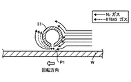
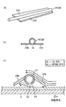
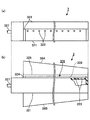
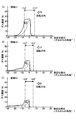
- FIG. 1 is a development view in which the apparatus is developed in a longitudinal direction in the rotation direction of the rotary table 2.
- reference numeral 31 denotes a first reactive gas nozzle which is a means for supplying BTBAS gas, and a region below the first gas nozzle 31 is configured as a first processing region P1.
- Reference numerals 41 and 42 denote separation gas nozzles as separation gas supply means.
- reaction gas nozzles and separation gas nozzles are formed on the turntable 2 so as to extend in the radial direction of the turntable 2, and BTBAS gas, which is a film forming gas, and separation gas along the radial direction downward.
- BTBAS gas which is a film forming gas, and separation gas along the radial direction downward.
- Each N 2 gas is discharged.
- the discharged N 2 gas is not directly exhausted from the separation region D, but is exhausted after going to the processing region. More specifically, the N 2 gas that flows from the separation region D toward the downstream side in the rotation direction of the turntable 2 as shown by the solid arrow in FIG. Passing over the upper portion of 31 and passing through a gap R provided between the reaction gas nozzle 31 and the ceiling surface 45 above the reaction gas nozzle 31, further to the outer position of the turntable 2 on the downstream side in the rotation direction from the reaction gas nozzle 31. The BTBAS gas discharged from the reaction gas nozzle 31 flows into the exhaust port provided and is exhausted.
- the present inventors have obtained the following knowledge as a result of studies on this apparatus.
- the rotational speed of the turntable 2 is low, it is considered that the BTBAS gas molecules are saturated below the gas nozzle 31 and are saturated and adsorbed to the wafer W.
- the turntable 2 is, for example, 120 rpm or more. Need to rotate at high speed.
- the rotational speed is increased in this way, as indicated by the solid line arrow in FIG. 2, the N 2 gas sinks below the reactive gas nozzle 31 due to an increase in the flow velocity, and the first processing region P1.
- the saturated adsorption of the BTBAS gas is not performed, and the amount of adsorption of the BTBAS molecules on the wafer W is proportional to the gas concentration and the contact time in the processing region P1.
- the gas concentration is reduced as described above, the adsorption amount of BTBAS gas molecules is reduced.
- the gas flow flowing toward a certain object has a property of flowing around to the back side where the pressure is low, assuming that the side of the object that receives the gas flow is the front side in terms of fluid dynamics. That is, the N 2 gas that flows toward the reaction gas nozzle 31 and sinks below the reaction gas nozzle 31 soars upward as viewed from the rotary table 2, and circulates downstream of the gas nozzle 31 in the rotation direction.
- the BTBAS gas discharged from the reaction gas nozzle 31 to the processing region P1 also rises upward from the turntable 2 in accordance with the flow of the N 2 gas.
- the BTBAS gas concentration in the region P1 is further lowered and the contact time of the BTBAS gas to the wafer W is shortened. As a result, the adsorption amount of BTBAS gas molecules is further reduced.
- the rotation speed of the turntable 2 is limited in order to increase the contact time of the reaction gas with the wafer W, to prevent the concentration of the reaction gas from decreasing, and to normally adsorb molecules contained in the reaction gas to the wafer W. Therefore, there is a possibility that the throughput cannot be sufficiently increased.
- the present invention has been made based on such circumstances, and one of its purposes is to sequentially supply a plurality of reaction gases that react with each other to the surface of a substrate in a vacuum vessel, and to produce a reaction product.
- a plurality of layers are stacked to form a thin film, and a first processing region to which a first reactive gas is provided along a circumferential direction of a turntable on which a substrate is placed is supplied, and a second reactive gas is supplied.
- Another object of the present invention is to provide a film forming apparatus capable of suppressing a decrease in film forming speed in a film forming apparatus provided with a second processing region and a separation region for separating the atmosphere of these processing regions.
- a film forming apparatus supplies at least two kinds of reaction gases that react with each other in a vacuum vessel in order to the surface of a substrate and executes this supply cycle, thereby generating a reaction product.
- a rotary table provided in the vacuum vessel, a substrate mounting area provided for mounting a substrate on the rotary table, and the rotary table
- the first reaction gas supply means and the second reaction for supplying the first reaction gas and the second reaction gas to the substrate, respectively, are fixedly provided above the turntable in the rotation direction of In order to separate the atmosphere of the gas supply means, the first processing region to which the first reaction gas is supplied, and the second processing region to which the second reaction gas is supplied, these processing regions in the rotation direction Between A separation region provided with a separation gas supply means for supplying a separation gas, and an exhaust port for evacuating the inside of the vacuum vessel, the first reaction gas supply means and the second reaction At least one of the gas supply
- the rectifying member may extend from the gas nozzle to both the upstream side and the downstream side, and each rectifying member has a larger width in the rotational direction, for example, at a portion away from the central portion side of the rotary table.
- the planar shape of the rectifying member may be formed in a fan shape.
- the separation area is located on both sides in the rotation direction of the separation gas supply means, for example, and a ceiling surface for forming a narrow space between the separation area and the turntable for the separation gas to flow from the separation area to the processing area side.
- a central region in which holes are formed may be provided.
- the central region is defined by the rotation central portion of the rotary table and the upper surface side of the vacuum vessel, and the separation gas is purged. is there.
- the exhaust port is provided so as to exhaust the reaction gas together with the separation gas diffusing on both sides of the separation region and the separation gas discharged from the central region.
- the exhaust ports may be provided on both sides of the separation region in the rotational direction when viewed in a plane in order to exhaust each reaction gas exclusively.
- the gas discharge holes of the separation gas supply means are arranged, for example, from one side to the other side of the rotation center portion and the peripheral portion of the rotary table, and the vacuum on the ceiling surface of the separation region A portion on the outer edge side of the container is bent so as to face the outer end surface of the turntable to form a part of the inner peripheral wall of the vacuum vessel, and a gap between the bent portion of the ceiling surface and the outer end surface of the turntable These may be set to dimensions that can prevent the invasion of reaction gas. Further, on the ceiling surface of the separation region, the upstream portion in the rotation direction of the rotary table relative to the separation gas supply means may be configured such that, for example, the portion located at the outer edge has a larger width in the rotation direction. Good.
- a film forming apparatus rotates a rotary table on which a plurality of substrates are placed in a vacuum vessel, and the substrates sequentially contact with reaction gases supplied to a plurality of different processing regions.
- a separation gas that is provided between the plurality of processing regions and prevents a different reaction gas from reacting in a space away from the substrate surface is provided.
- the height of the ceiling of the processing area from the surface of the substrate placed on the turntable may be formed higher than the ceiling of the separation area, and the height of the ceiling of the processing area in a plurality of different reaction areas. May be selectively determined according to the type of reaction gas supplied to the processing region and the amount of gas supplied.
- a gas nozzle that extends to intersect the moving direction of the substrate mounting area of the turntable and forms a reactive gas supply means that includes discharge holes formed along the length direction thereof;
- a rectifying member projecting from the gas nozzle toward at least one of the upstream side and the downstream side in the rotation direction of the turntable, and the rectifying member from one of the upstream side and the downstream side to the other side.
- the separation gas is guided to the flow space for allowing the separation gas to flow through the gas.
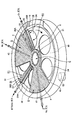
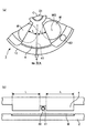
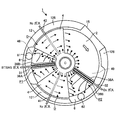
- FIG. 4 is a transverse plan view of the film forming apparatus of FIG. 3.
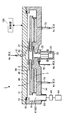
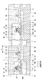
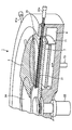
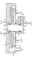
- FIG. 3 is a longitudinal cross-sectional view which shows an example of the process area
- a film forming apparatus includes a flat vacuum container 1 having a substantially circular planar shape as shown in FIG. 3 (a cross-sectional view taken along a line II ′ in FIG. 5 described later), A rotary table 2 provided in the vacuum vessel 1 and having a rotation center at the center of the vacuum vessel 1 is provided.
- the vacuum vessel 1 is configured such that the top plate 11 can be separated from the vessel body 12.
- the top plate 11 is pressed against the container main body 12 through a sealing member, for example, an O-ring 13 due to an internal decompression state, and maintains an airtight state.
- the top plate 11 is illustrated when the top plate 11 is separated from the container main body 12. It is lifted upward by a drive mechanism that does not.
- the rotary table 2 is fixed to a cylindrical core portion 21 at the center, and the core portion 21 is fixed to the upper end of a rotary shaft 22 extending in the vertical direction.
- the rotating shaft 22 penetrates the bottom surface portion 14 of the vacuum vessel 1 and its lower end is attached to a driving portion 23 that rotates the rotating shaft 22 around the vertical axis in this example in the clockwise direction.
- the rotating shaft 22 and the drive unit 23 are accommodated in a cylindrical case body 20 whose upper surface is open.
- a substrate placement area for placing a plurality of, for example, five wafers W along the rotation direction (or circumferential direction).
- a circular recess 24 is provided.
- the recess 24 is formed to have a diameter slightly larger than the diameter of the wafer W, and the wafer W is positioned and does not pop out due to the centrifugal force associated with the rotation of the turntable 2.
- the wafer W is drawn only in one recess 24 for convenience.
- the plurality of wafers W are placed on a common flat turntable 2, and when the wafer W is placed on the recess 24, the turntable 2 has a surface height of the wafer W and a surface of the turntable 2.
- the height is substantially the same.
- the substantially coincident height means that, for example, the difference between these heights is within 5 mm.
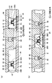
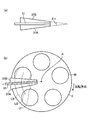
- FIG. 6 is a development view in which the rotary table 2 is cut along a concentric circle and expanded sideways.
- the recess 24 is formed so that the surface of the wafer and the surface of the turntable 2 (that is, the area on which the wafer is not placed) become substantially zero.
- the pressure fluctuation caused by the difference in height between the surface of W and the surface of the turntable 2 can be suppressed, and the in-plane uniformity of the film thickness can be made uniform.
- three elevating pins (described later) (see FIG. 12 described later) for supporting the back surface of the wafer W and moving the wafer W up and down and delivering the wafer W to and from the transfer mechanism 10.
- a penetrating through hole (not shown) is formed.
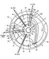
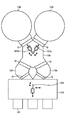
- the vacuum vessel 1 includes a first reactive gas nozzle 31, a second reactive gas nozzle 32, and two separated gas nozzles 41 at positions facing the passage area of the recess 24 in the rotary table 2.
- , 42 extend radially from the central portion at intervals from each other in the circumferential direction of the vacuum vessel 1 (the rotation direction of the rotary table 2).
- the reaction gas nozzles 31 and 32 and the separation gas nozzles 41 and 42 are attached to, for example, the side peripheral wall of the vacuum vessel 1, and the gas introduction ports 31 a, 32 a, 41 a, and 42 a, which are base ends thereof, pass through the side walls. Yes.
- the reaction gas nozzles 31 and 32 are respectively a gas supply source of BTBAS (Bistal Butylaminosilane) gas, which is a first reaction gas, and a gas supply source of O 3 (ozone) gas, which is a second reaction gas.
- the separation gas nozzles 41 and 42 are both connected to a gas supply source (not shown) of N 2 gas (nitrogen gas) which is a separation gas.
- N 2 gas nitrogen gas
- reaction gas nozzles 31, 32 discharge holes 33 for discharging the reaction gas are arranged on the lower side at intervals in the nozzle length direction.
- the diameter of the discharge port of each gas nozzle is 0.5 mm, and they are arranged at intervals of, for example, 10 mm along the length direction of each nozzle.
- the reaction gas nozzles 31 and 32 correspond to the first reaction gas supply unit and the second reaction gas supply unit, respectively, and the lower regions thereof are the first processing regions P1 and O 3 for adsorbing the BTBAS gas to the wafer W, respectively. It becomes the second processing region P2 for adsorbing the gas to the wafer W.
- the separation gas nozzles 41 and 42 are included in two separation regions D formed by the first ceiling surface 44, and each separation region D has a fan shape in plan view, and the rotation of the turntable 2. They are formed away from each other in the direction. Planar fan-shaped regions 48 and 49 are provided so as to be adjacent to these separation regions D. These regions 48 and 49 are hereinafter referred to as diffusion regions 48 and 49 in order to distinguish them from the names of other regions.
- the diffusion regions 48 and 49 are formed by the second ceiling surface 45 whose height from the turntable 2 is higher than the first ceiling surface 44 that forms the separation region D, and the processing regions P1 and P2. Are included in diffusion regions 48 and 49, respectively.
- the characteristics of reaction time, the rotational speed (or processing speed) of the rotary table 2, the size of the diffusion regions 48 and 49, that is, The length of the diffusion regions 48 and 49 in the rotation direction and the height position of the second ceiling surface 45 are appropriately designed.
- the reaction gas nozzles 31 and 32 are respectively provided in the central part in the rotational direction or on the upstream side in the rotational direction from the central part.
- the second reaction gas nozzle 42 rotates the diffusion region 49 as shown in FIG.
- the length of the diffusion region 49 provided upstream of the center of the direction and further including the second reaction gas nozzle 42 in the rotational direction is the length of the diffusion region 48 including the first reaction gas nozzle 41 in the rotation direction. Longer than that.
- the flow rate of the BTBAS gas from the first reaction gas nozzle 41 is set to, for example, 100 sccm, whereas the flow rate of O 3 gas from the second reaction gas nozzle 42 is set to, for example, 10000 sccm to ensure oxidation. Is set.
- the ceiling surface 45 of the diffusion region 49 is formed higher than the ceiling surface 45 of the diffusion region 48 in order to supply a relatively large flow rate of O 3 gas.
- FIG. 7A and 7B show an example in which the second ceiling surface 45 of each of the diffusion regions 48 and 49 is configured to have the same height, and the apparatus can be configured in this way. Good.
- FIG. 7B the flow of the separation gas is indicated by a solid arrow. 7, parts that are substantially the same as those in FIG. 6 are given the same reference numerals, and descriptions thereof are omitted.
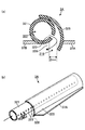
- the reactive gas nozzles 31 and 32 are provided with a nozzle cover 34 shown in FIG.
- the nozzle cover 34 includes a base portion 35 that extends along the length direction of the gas nozzles 31 and 32 and has a U-shaped longitudinal section.
- the base portion 35 covers the upper and side portions of the gas nozzles 31 and 32. Is done.
- the rectifying plate 36A and the rectifying plate 36B protrude in the horizontal direction from the left and right of the lower end of the base portion 35, that is, on the upstream side and the downstream side in the rotational direction of the turntable 2. As shown in FIGS.
- the plates 36 ⁇ / b> A and 36 ⁇ / b> B are formed so as to protrude from the base portion 35 toward the peripheral edge side from the center side of the turntable 2, and have a fan shape in plan view.
- the fan plates 36A and 36B forming the rectifying members are formed symmetrically with respect to the base portion 35, and the extended lines of the contour lines of the fan plates 36A and 36B shown by dotted lines in FIG.
- the angle (fan opening angle) ⁇ is, for example, 10 °.
- ⁇ is appropriately designed in consideration of the size in the circumferential direction of the separation region D to which N 2 gas is supplied and the size in the circumferential direction of the diffusion regions 48 and 49.
- ⁇ is 5 ° or more and 90 °. Is less than.
- the nozzle cover 34 has a fan table 36 ⁇ / b> A, 36 ⁇ / b> B whose front end side (or narrow side) is close to the protruding portion 5 and whose rear end side (or wide side) is a rotary table. It is provided so as to face the outer edge of 2. Further, the nozzle cover 34 is provided so as to be separated from the separation region D and between the second ceiling surface 45 via a gap R which is a gas flow space.
- the flow of each gas on the turntable 2 is indicated by dotted arrows, and as shown in FIG. 6, the gap R is a flow path for N 2 gas from the separation region D toward the processing regions P 1 and P 2. I am doing.
- the height of the gap R in the diffusion region 48 (the region where the reaction gas nozzle 31 is disposed) indicated by h3 in FIG. 6 is, for example, 10 mm to 70 mm, and the diffusion region 49 (the reaction gas nozzle 32 is disposed) indicated by h5.
- the height of the gap R in the region is, for example, 10 mm to 100 mm.
- the height from the surface of the wafer W to the second ceiling surface 45 in the diffusion region 48 indicated by h3 ′ is 15 to 100 mm, for example, 32 mm, and the wafer in the diffusion region 49 indicated by h5 ′.
- the height from the surface of W to the second ceiling surface 45 is, for example, 15 mm to 150 mm.
- the heights h3 and h5 of the gap R can be appropriately changed depending on the gas type and process conditions, and the separation gas (or N 2 gas) from the nozzle cover 34 is guided to the gap R for processing.
- the size is set such that the rectification effect for suppressing the flow into the regions P1 and P2 is as effective as possible.
- the heights h3 and h5 are preferably equal to or higher than the heights of the rotary table 2 and the lower ends of the gas nozzles 31 and 32.
- the lower surfaces of the fan plates 36A and 36B of the nozzle cover 34 are formed at the same height as the lower ends of the discharge ports 33 of the reaction gas nozzles 31 and 32.
- the height of fan plates 36A and 36B from the surface of turntable 2 (or the surface of wafer W) is 0.5 mm to 4 mm.
- the height h4 is not limited to 0.5 mm to 4 mm, but the N 2 gas is guided to the gap R as described above, and the reaction gas concentration in the processing regions P1 and P2 is processed on the wafer W. It may be set to a height that can secure a sufficient concentration so that, for example, 0.2 mm to 10 mm may be used.
- the fan plates 36A and 36B of the nozzle cover 34 reduce the flow rate of the N 2 gas entering from the separation region D below the gas nozzles 31 and 32, as will be described later, and are supplied from the reaction gas nozzles 31 and 32, respectively. It has a role of restricting and preventing the BTBAS gas and O 3 gas from rising from the turntable 2, and if it can fulfill this role, it is not limited to being provided at the position shown here.
- the rotation speed increases from the rotation center toward the peripheral edge of the rotary table 2.
- the same flow rate of gas is supplied to the central side of the rotating rotary table and the peripheral edge side.
- the gas concentration on the peripheral edge side tends to be lower than that on the central side.
- the reaction gas nozzles 31 and 32 and the separation gas nozzles 41 and 42 are provided so as to extend from the outer peripheral side of the vacuum vessel 1 toward the rotation center of the rotary table 2 and are separated into the nozzles from the outer peripheral side. Gas and reaction gas are supplied.
- the flow rate can be increased toward the peripheral edge side of the rotary table 2 if, for example, the diameters of the gas holes are the same in the length direction.
- the diameter of the gas hole of each nozzle it is preferable at the point which can form such a discharge flow rate distribution easily.
- Such a discharge flow rate distribution in the length direction of the nozzle is preferable in that it can suppress a decrease in gas concentration on the peripheral edge side, and the gas concentration in the length direction of the turntable 2 can be made uniform.
- the fan plates 36A and 36B extend in the rotation direction of the rotary table, and the fan plates 36A and 36B are below the fan plates 36A and 36B. It is possible to reduce the flow rate of the N 2 gas that sinks into the gas and to improve the concentration of the reaction gas below the fan plates 36A and 36B. Further, by adjusting the length of the fan plates 36A and 36B in the rotation direction, the area of the area for controlling the concentration of the reaction gas and the amount of N 2 gas guided to the gap R can be adjusted.
- discharge holes 40 for discharging the separation gas are formed on the lower side at intervals in the length direction.
- the diameter of the discharge port of each gas nozzle is 0.5 mm.
- the nozzles are arranged at intervals of 10 mm along the length direction of each nozzle.
- These separation gas nozzles 41 and 42 are for forming a separation region D for separating the first processing region P1 and the second processing region P2, and the top of the vacuum vessel 1 in the separation region D.
- the plate 11 is formed by dividing a circle drawn around the rotation center of the turntable 2 and along the vicinity of the inner peripheral wall of the vacuum vessel 1 in the circumferential direction.
- a convex portion 4 having a sector shape and protruding downward is provided.
- the separation gas nozzles 41 and 42 are accommodated in a groove 43 formed so as to extend in the radial direction of the circle at the circumferential center of the circle in the convex portion 4.
- the distance from the central axis of the separation gas nozzle 41 (or 42) to the fan-shaped edges (the upstream edge and the downstream edge in the rotation direction) of the convex portion 4 is set to the same length.
- the groove portion 43 is formed so as to bisect the convex portion 4.
- the upstream side in the rotational direction of the rotary table 2 in the convex portion 4 is the rotational direction. It may be formed so as to be wider than the downstream side.
- a flat low ceiling surface 44 (or a first ceiling surface) that is a lower surface of the convex portion 4 exists on both sides in the circumferential direction of the separation gas nozzles 41 and 42, and both sides of the ceiling surface 44 in the circumferential direction are present.
- the ceiling surface 45 (or the second ceiling surface) higher than the ceiling surface 44 exists, and these constitute the lower surface of the top plate 11.
- the role of the convex portion 4 is a separation space that is a narrow space for preventing the first reactive gas and the second reactive gas from entering the rotary table 2 to prevent the mixing of the reactive gases. Is to form.
- the O 3 gas is prevented from entering from the upstream side in the rotation direction of the turntable 2, and the BTBAS gas is prevented from entering from the downstream side in the rotation direction.
- Preventing gas intrusion means that the N 2 gas, which is the separation gas discharged from the separation gas nozzle 41, diffuses between the first ceiling surface 44 and the surface of the turntable 2. It blows out to the space below the 2nd ceiling surface 45 adjacent to the 1 ceiling surface 44, and this means that the gas from the said adjacent space cannot penetrate
- the "gas can not be penetration” does not mean only if it can not completely penetrate the lower side space of the convex portion 4 from the adjacent space, although somewhat invading, O 3 were respectively entering from both sides This also means a case where a state in which the gas and the BTBAS gas are not mixed in the convex portion 4 is ensured. As long as such an action is obtained, the atmosphere of the first processing region P1 which is the role of the separation region D and the first The separation effect from the atmosphere of the second processing region P2 can be exhibited.
- the degree of narrowing in the narrow space is the pressure between the narrow space (that is, the space below the convex portion 4) and the area adjacent to the space (that is, the space below the second ceiling surface 45 in this example). It can be said that the difference is set to a size that can ensure the effect of “the gas cannot enter”, and the specific dimensions thereof vary depending on the area of the convex portion 4 and the like. Further, the gas adsorbed on the wafer can naturally pass through the separation region D, and the prevention of gas intrusion means the gas in the gas phase.
- the separation gas is not limited to N 2 gas, and the type of gas is not particularly limited as long as it does not affect the film forming process.
- a protruding portion 5 is provided so as to face a portion on the outer peripheral side of the core portion 21 in the rotary table 2 and along the outer periphery of the core portion 21.
- the projecting portion 5 is formed continuously with the portion on the rotation center side of the convex portion 4, and the lower surface thereof is formed at the same height as the lower surface (ceiling surface 44) of the convex portion 4.
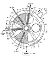
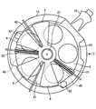
- 4 and 5 show the top plate 11 cut horizontally at a position lower than the second ceiling surface 45 and higher than the separation gas nozzles 41 and 42.
- the protrusion part 5 and the convex-shaped part 4 are not necessarily restricted to integral, The separate body may be sufficient.
- the convex portion 4 has a circumferential length (that is, the rotary table 2) at the boundary portion with the protruding portion 5 that is 140 mm away from the rotation center.
- the length of the circular arc of concentric circles) is, for example, 146 mm
- the circumferential length is, for example, 502 mm at the outermost portion of the wafer mounting area (that is, the recess 24).
- the circumferential length L of the convex portion 4 located on the left and right sides from both sides of the separation gas nozzle 41 (or 42) is 246 mm. As shown in FIG.
- the height h1 of the lower surface of the convex portion 4 from the surface of the turntable 2 on the ceiling surface 44 is, for example, 0.5 mm to 4 mm, and the turntable from the lower end of the separation gas nozzle 41 (or 42).
- the height h2 to the surface of 2 is 0.5 mm to 4 mm.
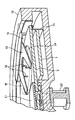
- FIGS. 4 and 9 show respective longitudinal sections of the region where the high second ceiling surface 45 and the low first ceiling surface 44 are provided.
- the peripheral edge portion of the fan-shaped convex portion 4 (that is, the portion on the outer edge side of the vacuum vessel 1) is L-shaped so as to face the outer end surface of the rotary table 2.
- a bent portion 46 is formed by bending.
- the bent portion 46 is also provided for the purpose of preventing the reaction gas from entering from both sides in the same manner as the convex portion 4 and preventing the mixture of both reaction gases.
- the inner peripheral surface of the bent portion 46 and the rotary table are provided. 2 and the gap between the outer peripheral surface of the bent portion 46 and the container body 12 are set to the same dimensions as the height h1 of the ceiling surface 44 with respect to the surface of the turntable 2.
- the inner peripheral wall of the container main body 12 is formed in a vertical plane close to the outer peripheral surface of the bent portion 46 as shown in FIG. 8, but in a portion other than the separation region D, FIG.
- the vertical cross-sectional shape is cut out in a rectangular shape from the portion facing the outer end surface of the turntable 2 to the bottom surface portion 14 and is recessed outward. If this recessed portion is called an exhaust region 6, for example, two exhaust ports 61 and 62 are provided at the bottom of the exhaust region 6 as shown in FIGS. These exhaust ports 61 and 62 are respectively connected to a common vacuum pump 64 which is a vacuum exhaust means via an exhaust pipe 63.
- a common vacuum pump 64 which is a vacuum exhaust means via an exhaust pipe 63.
- reference numeral 65 denotes a pressure adjusting means, which may be provided for each of the exhaust ports 61 and 62 or may be shared. With such a structure, an exhaust flow toward the outside of the turntable 2 can be formed, and the gas supplied to the vacuum vessel 1 can be exhausted.
- the exhaust ports 61 and 62 are not limited to opening downward, but open upward or sideward. It may be a simple configuration. Further, when the exhaust port is provided in the inner region from the peripheral end of the turntable 2, the exhaust port may be provided so as to open upward or laterally. However, in consideration of suppressing the generation of particles, the downward opening is provided. It is preferable. Further, the normal vacuum vessel 1 is provided at an upper position away from the floor, for example, in order to easily perform maintenance or the like. Therefore, when the exhaust ports 61 and 62 are opened downward, the exhaust pipe 63 can also be drawn downward, and the pipe 63 can be routed to the space between the floor and the vacuum vessel 1. The installation space can be reduced.
- the exhaust port 61 (or 62) or a portion for exhausting more gas in the vacuum vessel 1 corresponding to the exhaust port is located downstream of the reaction gas nozzle 31 (or 32) in the rotation direction of the turntable 2. Further, the position is preferably in the diffusion region 48 (or 49) including the reactive gas nozzle 31 (or 32) or on the outer peripheral side of the diffusion region 48 (or 49). With such an arrangement, it is possible to prevent the reaction gas from flowing backward with respect to the rotation direction or toward the inner peripheral side without going to the outer peripheral side of the turntable 2. Further, the separation gas smoothly flows into the exhaust ports 61 and 62 through the gap R by the rectifying action of the fan plates 36A and 36B.
- the exhaust ports 61 and 62 are provided in the exhaust region 6, respectively.
- the exhaust region 6 is disposed on the radially outer side of the turntable 2 in the first and second diffusion regions 48 and 49, but is not provided on the radially outer side of the turntable 2 in the separation region D. . Therefore, due to the rectifying action of the fan plates 36A and 36B and the arrangement of the exhaust ports 61 and 62, the gases supplied from the gas nozzles smoothly flow into the exhaust ports 61 and 62 and diffuse on the rotary table 2. In the regions 48 and 49, a flow is formed in which the first and second reaction gases are separated.
- the exhaust ports 61 and 62 are provided on both sides in the rotational direction of the separation region D when viewed in a plane so that the separation action of the separation region D works reliably, and each reaction gas (BTBAS gas and O 3 gas). Is exhausted exclusively.
- the exhaust port 61 is provided between the first reaction gas nozzle 31 and the separation region D adjacent to the reaction gas nozzle 31 on the downstream side in the rotation direction, and the exhaust port 62 is connected to the second reaction gas nozzle 32 and the reaction gas. It is provided between the separation region D adjacent to the gas nozzle 32 on the downstream side in the rotation direction.
- the exhaust port 61 may be provided between the first reactive gas nozzle 31 and the separation region D adjacent to the reactive gas nozzle 31 on the upstream side in the rotation direction, and the exhaust port 62 may The reaction gas nozzle 32 and the separation region D adjacent to the reaction gas nozzle 32 on the upstream side in the rotation direction may be provided.
- a heater unit 7 is provided in the space between the turntable 2 and the bottom surface portion 14 of the vacuum vessel 1, and the temperature on the wafer on the turntable 2 is determined by a process recipe.
- reference numeral 71 denotes a cover member whose upper edge is bent outward and formed into a flange shape, and prevents gas from entering the inside from the outside.
- the bottom surface portion 14 in the portion closer to the rotation center than the space where the heater unit 7 is disposed is near the center portion of the lower surface of the turntable 2 and is close to the core portion 21, and the space therebetween is narrow.
- reference numeral 73 denotes a purge gas supply pipe for purging the arrangement space of the heater unit 7.
- the flow of purge gas is indicated by arrows, and the space from the inside of the case body 20 to the arrangement space of the heater unit 7 is purged with N 2 gas, and this purge gas is interposed between the rotary table 2 and the cover member 71.
- the air is exhausted from the gap to the exhaust ports 61 and 62 through the exhaust region 6. This prevents the BTBAS gas or the O 3 gas from flowing from one of the first processing region P1 and the second processing region P2 described above to the other through the lower part of the turntable 2, so that this purge gas is It also plays the role of separation gas.
- a separation gas supply pipe 51 is connected to the center of the top plate 11 of the vacuum vessel 1 so that N 2 gas as separation gas is supplied to a space 52 between the top plate 11 and the core portion 21. It is configured.
- the separation gas supplied to the space 52 is discharged toward the periphery along the surface of the turntable 2 on the wafer mounting region side through a narrow gap 50 between the protruding portion 5 and the turntable 2. Since the space surrounded by the protrusion 5 is filled with the separation gas, the reaction gas (BTBAS gas) is interposed between the first processing region P1 and the second processing region P2 via the center of the turntable 2. Alternatively, mixing of O 3 gas) is prevented.
- this film forming apparatus is partitioned by the rotation center portion of the turntable 2 and the vacuum vessel 11 in order to separate the atmosphere of the first processing region P1 and the second processing region P2, and the separation gas is purged.
- the discharge port for discharging the separation gas on the surface of the turntable 2 includes the central region C formed along the rotation direction.
- the discharge port here corresponds to a narrow gap 50 between the protruding portion 5 and the rotary table 2.
- a transfer port 15 for transferring a wafer between the external transfer arm 10 and the rotary table 2 is formed on the side wall of the vacuum container 1.
- the port 15 is opened and closed by a gate valve (not shown).
- the film forming apparatus of this embodiment is provided with a control unit 100 including a computer for controlling the operation of the entire apparatus, and a program for operating the apparatus is stored in the memory of the control unit 100. ing.
- This program has a set of steps so as to execute the operation of the apparatus described later, and is installed in the control unit 100 from a storage medium such as a hard disk, a compact disk, a magneto-optical disk, a memory card, or a flexible disk.
- a gate valve (not shown) is opened, and the wafer is transferred from the outside into the recess 24 of the turntable 2 through the transfer port 15 by the transfer arm 10.
- This delivery is performed by raising and lowering the lift pins 16 from the bottom side of the vacuum vessel through the through holes in the bottom surface of the recesses 24 as shown in FIG. 12 when the recesses 24 stop at the position facing the transport port 15. .
- the delivery of the wafer W is performed by intermittently rotating the turntable 2, and the wafer W is placed in each of the five recesses 24 of the turntable 2.
- the inside of the vacuum vessel 1 is evacuated to a preset pressure by the vacuum pump 64 and the wafer W is heated by the heater unit 7 while rotating the rotary table 2 clockwise.
- the turntable 2 is heated in advance to, for example, 300 ° C. by the heater unit 7, and the wafer W is heated by being placed on the turntable 2.
- the BTBAS gas and the O 3 gas are discharged from the first reaction gas nozzle 31 and the second reaction gas nozzle 32, respectively, and the separation gas nozzle 41 is discharged.
- 42 is discharged with N 2 gas which is a separation gas.
- N 2 gas as separation gas is also supplied from the separation gas supply pipe 51, and thereby, from the central region C, that is, between the protrusion 5 and the center of the turntable 2, to the surface of the turntable 2. Along with this, N 2 gas is discharged.
- the N 2 gas supplied from the separation gas nozzles 41 and 42 passes through the regions where the reaction gas nozzles 31 and 32 are arranged, respectively. It flows into the exhaust ports 61 and 62.
- the N 2 gas stream flows below the reaction gas nozzles 31 and 32 as described in the section of the problem to be solved by the invention.
- the inventors have intensively studied on this problem, and in the present embodiment, the fan plates 36A and 36B are attached to the gas nozzles 31 and 32 in order to suppress the downward flow.
- the N 2 gas discharged downward from the separation gas nozzles 41 and 42 hits the surface of the turntable 2 (both the surface of the wafer W and the surface of the non-mounting area of the wafer W), and the upstream side in the rotation direction along the surface. Go downstream. Further, the BTBAS gas and the O 3 gas discharged downward from the respective reaction gas nozzles 31 and 32 strike the surface of the turntable 2 and ride on the flow of the separation gas toward the downstream side in the rotation direction.
- the inner peripheral wall of the container body 12 along the space below the second ceiling surface 45 where the reaction gas nozzles 31 and 32 are arranged is notched and widened as described above. Since the exhaust ports 61 and 62 are located below the wide space, the second ceiling surface is smaller than the narrow space below the first ceiling surface 44 and the pressure in the central region C. The pressure in the space below 45 is lower.
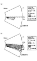
- FIG. 13 schematically shows the state of the gas flow on the turntable 2 discharged from each part
- FIG. 14 shows the apparatus vertically cut along the circumferential direction of the turntable 2 and developed on the paper surface.
- FIG. 14 shows the apparatus vertically cut along the circumferential direction of the turntable 2 and developed on the paper surface.
- FIG. 14 shows the flow of each gas for convenience.
- the processing areas P1 and P2 and the separation area D and the exhaust ports 61 and 62 are shown on the same plane.
- FIG. 14 shows an apparatus in which the height of the second ceiling surface 45 of the diffusion regions 48 and 49 is set to the same height as in FIG. 7A for convenience. Also when the height positions of the respective second ceiling surfaces 45 are different as shown in FIG. 6, the respective gases flow in the same manner as in FIG.
- each gas on the turntable 2 will be described with reference to FIGS. 13 and 14.
- the N 2 gas discharged from the separation gas nozzle 41 and flowing downstream in the rotation direction is separated from the separation region D into the second ceiling surface. 45, and the exhaust gas is exhausted by the exhaust port 61 provided on the downstream side of the first reactive gas nozzle 31, so that the downstream side of the first reactive gas nozzle is below the ceiling surface 45. It flows toward 31.
- the flow of the N 2 gas around the first reactive gas nozzle 31 is indicated by a solid line arrow.
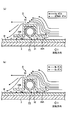
- BTBAS gas is discharged to the first processing region P1 below the reactive gas nozzle 31, and the flow is indicated by dotted arrows. Since the discharged BTBAS gas is restricted by the fan plates 36A and 36B from rising from below the fan plates 36A and 36B, the lower region of the fan plates 36A and 36B is the upper region of the fan plates 36A and 36B.
- the pressure is higher than
- the flow of N 2 gas heading from the upstream side in the rotation direction toward the reaction gas nozzle 31 is restricted by the pressure difference and the fan plate 36A protruding upstream in the rotation direction. Dive is prevented and heads downstream.
- the N 2 gas travels in the rotational direction toward the downstream side of the first reactive gas nozzle 31 through a gap R provided between the nozzle cover 34 and the ceiling surface 45. That is, the fan plate 36 ⁇ / b> A is arranged at a position where most of the N 2 gas traveling from the upstream side to the downstream side of the reactive gas nozzle 31 can be guided to the gap R by bypassing the lower side of the reactive gas nozzle 31. Therefore, the amount of N 2 gas flowing into the first processing region P1 is suppressed.
- the N 2 gas flowing into the first processing region P1 has a pressure on the downstream side (back side) as compared to the upstream side (front side) of the reaction gas nozzle 31 that receives the gas. Therefore, the BTBAS gas discharged from the reaction gas nozzle 31 and moving toward the downstream side in the rotation direction also rises from the turntable 2 due to the rise toward the downstream position of the reaction gas nozzle 31.
- the fan plate 36B provided on the downstream side in the rotation direction prevents the BTBAS gas and the N 2 gas from rising by limiting the fan plate 36B and the rotary table. 2 flows downstream, and merges with the N 2 gas that has flowed downstream through the gap R on the upper side of the reaction gas nozzle 31 on the downstream side of the processing region P1.
- the N 2 gas supplied from the BTBAS gas and the separation gas nozzle 41 is pushed by the N 2 gas directed upstream from the separation gas nozzle 42 located on the downstream side of the processing region P1, and the separation gas nozzle 42 is provided. was it been prevented from entering the lower side of the convex portion 4, the exhaust through the N 2 gas from the separation gas nozzle 42, an exhaust region 6 with N 2 gas is discharged from the center area C The air is exhausted from the port 61.
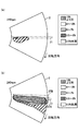
- the N 2 gas discharged from the separation gas nozzle 42 and flowing downstream in the rotation direction flows from the separation region D to the lower side of the second ceiling surface 45, and is provided downstream of the second reaction gas nozzle 32. Since the exhaust is performed by the exhaust port 62, the exhaust flows toward the second reactive gas nozzle 32 below the ceiling surface 45.
- O 3 gas is discharged to the second processing region P2 below the reactive gas nozzle 32, and the flow is indicated by a dotted arrow in FIG. Since the discharged O 3 gas is restricted by the fan plates 36A and 36B from rising from below the fan plates 36A and 36B, the lower region of the fan plates 36A and 36B is located above the fan plates 36A and 36B. The pressure is higher than the area.
- the flow of the N 2 gas from the upstream side in the rotation direction toward the reaction gas nozzle 32 is restricted by such a pressure difference and the fan plate 36A protruding upstream in the rotation direction. Therefore, the N 2 gas is prevented from entering the processing region P 2 below the reactive gas nozzle 32, and is provided on the nozzle cover 34 between the nozzle cover 34 and the ceiling surface 45 toward the downstream side. It flows through the gap R to the downstream side of the processing region P2. That is, the fan plate 36A is arranged at a position where most of the N 2 gas traveling from the upstream side to the downstream side of the reactive gas nozzle 32 can be guided to the gap R by bypassing the lower side of the reactive gas nozzle 32. Therefore, the amount of N 2 gas flowing into the second processing region P2 is suppressed.
- the N 2 gas flowing into the second processing region P2 has a lower pressure on the downstream side (back side) than the upstream side (front side) of the reaction gas nozzle 32 that receives the N 2 gas flow. From this point, the reaction gas nozzle 32 tends to rise toward the downstream position, and the O 3 gas discharged from the reaction gas nozzle 32 toward the downstream side in the rotation direction also rises to that position. However, as shown in FIG. 15 (b), the fan plate 36B provided on the downstream side in the rotation direction prevents the O 3 gas and N 2 gas from rising and is prevented from rotating with the fan plate 36B. It goes downstream with the table 2 and merges with the N 2 gas that has flowed downstream through the gap R on the upper side of the reactive gas nozzle 32 on the downstream side of the processing region P2.
- the wafer W alternately passes through the first processing region P1 in which the first reaction gas nozzle 31 is provided and the second processing region P2 in which the second reaction gas nozzle 32 is provided by the rotation of the turntable 2, so that the BTBAS.
- Gas is adsorbed and then O 3 gas is adsorbed to oxidize BTBAS molecules to form one or more silicon oxide molecular layers.
- silicon oxide molecular layers are sequentially stacked to form silicon having a predetermined thickness. An oxide film is formed.
- the height of the ceiling surface 44 of the convex portion 4 and the length in the circumferential direction are determined by the gas intrusion to the lower side of the ceiling surface 44 in the process parameters during operation including the flow rate of each gas. Therefore, the BTBAS gas and the O 3 gas can hardly reach the lower part of the fan-shaped convex portion 4 or can reach the vicinity of the separation gas nozzle 41 even if it flows slightly. Instead, it is pushed back upstream and downstream in the rotational direction by the N 2 gas discharged from the separation gas nozzle 41 and exhausted as described above.
- each separation region D invasion of BTBAS gas or O 3 gas which is a reactive gas flowing in the atmosphere is prevented, but the gas molecules adsorbed on the wafer remain as they are in the separation region, that is, the fan-shaped convex portion 4. It passes under the low ceiling surface 44 due to the above and contributes to film formation.
- the wafers are sequentially carried out by the transfer arm 10 by an operation reverse to the carry-in operation.
- the rotation speed of the turntable 2 is, for example, 1 rpm to 500 rpm
- the process pressure is, for example, 1067 Pa (8 Torr)
- the heating temperature is 350 ° C.
- the flow rates of BTBAS gas and O 3 gas are 100 sccm and 10000 sccm, respectively
- the flow rate of N 2 gas from the separation gas nozzles 41 and 42 is 20000 sccm
- the flow rate of N 2 gas from is, for example, 5000 sccm.
- the number of reaction gas supply cycles for one wafer that is, the number of times the wafer passes through each of the processing regions P1 and P2, varies depending on the target film thickness, but is many times, for example, 6000 times.
- What can be said from the ratio of the gas flow rate as described above is that the gas flow in the first processing region P1 and the second processing region P2 is greatly influenced by the N 2 gas supplied from the separation region D. Therefore, it is important to suppress the inflow of N 2 gas into the first processing region P1 and the second processing region P2, and for this purpose, it is effective to provide the fan plates 36A and 36B as described above.
- the separation region D is located above the first reaction gas nozzle 31 provided on the turntable 2 on which the wafer W is placed, and the rotation direction of the turntable 2 is changed from the upstream side to the downstream side.
- nozzle cover 34 to the first reaction gas nozzle 31 with a clearance R is provided with a fan plate 36A protruding to the upstream side of the rotational direction forming an through passage of N 2 gas is provided toward.
- the concentration of BTBAS gas in the first processing region P1 can be suppressed, and even when the rotation speed of the turntable 2 is increased, the BTBAS gas molecules are reliably adsorbed on the wafer W and can be normally formed.
- a membrane can be performed. Accordingly, the deposition rate on the wafer W is improved, and the throughput can be improved. Further, the film can be formed on the wafer W with high uniformity. Furthermore, the film quality is improved, that is, a film having a desired property can be obtained.
- the nozzle cover 34 is provided with a fan plate 36B so as to protrude downstream in the rotation direction.
- the N 2 gas that has flowed from the separation region D on the upstream side to the first processing region P1 by the fan plate 36B is first from the rotary table 2 together with the BTBAS gas discharged from the processing region P1 from the reaction gas nozzle 31.
- Ascending to the back surface of the first reactive gas nozzle 31 on the downstream side in the rotational direction of the reactive gas nozzle 31 is suppressed. Therefore, the decrease in the concentration of the BTBAS gas in the processing region P1 and the contact time of the BTBAS gas with the wafer W can be suppressed, so that even when the rotation speed of the turntable 2 is increased, the molecules of the BTBAS gas are increased. Can be reliably adsorbed to the wafer W and film formation can be performed normally. As a result, throughput can be improved. In addition, the film can be formed on the wafer W with high uniformity, and the film quality can be improved.
- the N 2 gas flow path from the upstream side to the downstream side in the rotation direction of the turntable 2 is also provided above the second reaction gas nozzle 32 in the same manner as the first reaction gas nozzle.
- the second reaction gas nozzle 32 is provided with a nozzle cover 34 provided with a fan plate 36A protruding upstream in the rotation direction.
- the N 2 gas can be prevented from flowing into the second processing region P2, and the O 3 gas concentration in the second processing region P2 can be suppressed from decreasing. Therefore, even when the rotation speed of the turntable 2 is high, BTBAS can be sufficiently oxidized and a film with less impurities can be formed, so that the film formation rate can be increased. As a result, throughput can be improved. In addition, the film can be formed on the wafer W with high uniformity, and the film quality can be improved.
- the second reaction gas nozzle 32 is also provided with a fan plate 36B protruding toward the downstream side in the rotation direction.
- the fan 36B is separated from the separation region D into the second processing region P2. Since the flow of N 2 gas is suppressed from rising from the rotary table 2 to the downstream side in the rotation direction of the second reaction gas nozzle 32 along with the O 3 gas discharged from the reaction gas nozzle 32 from the processing region P2, in the process area P2 with the concentration of O 3 gas is suppressed to be reduced time of contact with the O 3 gas and the wafer W is suppressed to be reduced.
- the BTBAS can be sufficiently oxidized and a film with less impurities can be formed, so that the film formation rate can be increased. As a result, throughput can be improved.
- the film can be formed on the wafer W with high uniformity, and the film quality can be improved.
- the gas nozzles 31 and 32 In order to suppress the inflow of N 2 gas, which is a separation gas, between the gas nozzles 31 and 32 and the rotary table by forming a pressure difference above and below the gas nozzles 31 and 32, the gas nozzles 31 and 32
- the fan plate 36A may be protruded only on the upstream side in the rotation direction. However, since the pressure difference can be more reliably formed by projecting the fan plate 36B to the downstream side in the rotation direction, the above-described effect can be obtained with certainty. Further, in order to restrict and prevent the reaction gas from rising, the fan plate 36B may be protruded from the gas nozzles 31 and 32 only to the downstream side in the rotation direction.
- the separation gas flows from the upstream side in the rotation direction of the turntable 2 to the reaction gas nozzles 31 and 32, but each of the separation gas nozzles 41 and 42, the reaction gas nozzles 31 and 32, and the exhaust ports 61 and 62.
- the separation gas may be directed to the reaction gas nozzles 31 and 32 from both upstream and downstream directions in the rotation direction.
- the fan plate 36B protruding to the downstream side forms a pressure difference above and below the reaction gas nozzle 31 from the downstream side. , 32 is guided to the gap R.
- the fan plate 36B plays a role similar to that of the fan plate 36A for the separation gas flowing from the upstream side in the rotation direction with respect to the separation gas flowing from the downstream side in the rotation direction to the reaction gas nozzles 31 and 32.
- the separation gas is also directed to the reaction gas nozzles 31 and 32 from the downstream side in the rotation direction, the reaction gas rises to the upstream side in the rotation direction of the reaction gas nozzles 31 and 32 by the separation gas to the upstream side. It can be limited and prevented by the protruding fan plate 36A. That is, the fan plate 36A plays a role similar to that of the fan plate 36B for the separation gas flowing from the upstream side in the rotation direction with respect to the separation gas flowing from the downstream side in the rotation direction.
- the fan plate may be provided only on the downstream side in the rotation direction.
- the separation gas directed from the downstream side toward the reaction gas nozzles 31 and 32 can be guided to the gap R to prevent a decrease in the concentration of the reaction gas in the processing regions P1 and P2.
- the processing gas that can be used in the present embodiment includes DCS [dichlorosilane], HCD [hexachlorodisilane], TMA [trimethylaluminum], 3DMAS [trisdimethylaminosilane], TEMAZ [tetrakisethylmethyl] in addition to the above-described examples.
- Aminozirconium] TEMHF [tetrakisethylmethylaminohafnium], Sr (THD) 2 [strontium bistetramethylheptanedionato], Ti (MPD) (THD) 2 [titanium methylpentanedionatobistetramethylheptandionato], And monoaminosilane.
- the upstream side portion of the turntable 2 in the rotation direction with respect to the separation gas nozzles 41 and 42 has a larger width in the rotation direction as a portion located on the outer edge. The reason is that the flow of the gas from the upstream side toward the separation region D by the rotation of the turntable 2 is so fast that it approaches the outer edge. From this point of view, it is a good idea to configure the convex portion 4 in a fan shape as described above.
- the first ceiling surface 44 which forms a narrow space located on both sides of the separation gas supply nozzle 41 (42), has the separation gas supply nozzle 41 shown in FIGS. 16 (a) and 16 (b).
- the width dimension L along the rotation direction of the turntable 2 is 50 mm or more at the portion through which the center WO of the wafer W passes. .
- the distance between the first ceiling surface 44 and the turntable 2 is set to a certain size, the speed of the turntable 2 increases as the distance from the rotation center of the turntable 2 increases.
- the width dimension L required to obtain the intrusion prevention effect becomes longer as the distance from the rotation center increases.
- the width dimension L in the portion through which the center WO of the wafer W passes is smaller than 50 mm, the distance between the first ceiling surface 44 and the turntable 2 needs to be considerably reduced.
- a device for suppressing the swing of the rotary table 2 as much as possible is required.
- the width dimension L is smaller than 50 mm, the width dimension L is preferably 1/10 to 1/1 of the diameter of the wafer W, and more preferably about 1/6 or more.
- the reaction gas nozzles 31 and 32 may be provided with only a fan plate without providing the base 34.
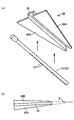
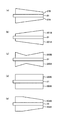
- FIG. 17A shows a reactive gas nozzle 31 (or 32) provided with fan plates 37A and 37B configured in the same manner as the fan plates 36A and 36B so as to protrude from the lower end to the upstream side and the downstream side in the rotation direction, respectively.
- FIG. 17B is a longitudinal sectional view of the reactive gas nozzle 31 (or 32). Further, the distance from the rotation center of the turntable 2 toward the outer edge of the turntable 2 increases the moving distance of the turntable 2 and the gas flow on the turntable 2 becomes faster.
- the rectifying plates provided in the reaction gas nozzles 31 and 32 in order to reliably regulate the flow of each gas, the further away from the rotation center of the rotary table 2, the larger the upstream in the rotational direction and the downstream. Since it is preferable to project, it is preferable to form the rectifying plate so that its planar shape is a fan like 36A, 36B, 37A, 37B.
- the direction in which the current plate protrudes is not limited to the horizontal direction as in the above examples.
- the fan plates 37A and 37B may be provided so as to protrude obliquely downward from the reaction gas nozzle 31 as shown in FIG.
- the current plate is fan-shaped for the above reasons.
- the rectifying plate only needs to cover a portion where the gas concentration is reduced in the processing region, and therefore the shape can be freely changed according to the gas concentration.
- 18A shows the upper surface side of the gas nozzle 31 to which the above-described fan plates 37A and 37B shown in FIG. 17A are attached
- FIGS. 18B to 18D show the fan plates 37A and 37B.
- the upper surface side of the gas nozzle 31 to which the rectifying plates 301A to 304A and 301B to 304B having shapes different from the fan plates 37A and 37B are attached is shown.
- the current plate is not limited to the fan shape.
- the rectifying plate may be integrated with the reactive gas nozzle and have a rectifying function. Further, the current plate may be formed separately from the reactive gas nozzle.
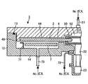
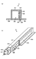
- the reactive gas nozzle 3 includes an elongated rectangular tube-shaped nozzle body 321 and a guide plate 325 provided on a side surface of the nozzle body 321.
- the aforementioned fan plates 37A and 37B are provided at the lower ends of the nozzle body 321 and the guide plate 325 so as to sandwich the nozzle body 321 and the guide plate 325.
- the interior of the nozzle body 321 is hollow, and constitutes a flow space 322 for allowing the reaction gas supplied from the gas introduction pipe 327 provided at the base end of the nozzle body 321 to flow.
- a diameter of 0.5 mm is provided on one side of the side wall portion that is a tube wall of the nozzle body 321, for example, on the upstream side wall portion as viewed from the rotation direction of the rotary table 2.
- a plurality of reaction gas outflow holes 323 are arranged along the length direction of the nozzle body 321 with an interval of, for example, 5 mm.
- a guide plate 325 is fixed to the side wall portion through a gap adjusting member 324 so as to be parallel to the side wall portion.
- FIG. 20A is a side view of the reactive gas nozzle 3 with the guide plate 325 removed. As shown in FIG.
- the gap adjusting member 324 is composed of a plurality of plates having the same thickness, and surrounds the region where the reaction gas outflow holes 323 in the side wall of the nozzle body 321 are arranged, for example, It arrange
- the space surrounded by the outer surface of the side wall portion, the gap adjusting member 324, and the guide plate 325 has a flat belt-like gas flow space 326 through which the gas discharged from the reaction gas outflow hole 323 flows.
- the gap adjusting member 324 is not disposed on the lower side of the region where the reaction gas outflow holes 323 are arranged, the gas flow space 326 is shown in the bottom view of FIG.
- the reaction gas nozzle 3 is arranged on the radius of the turntable 2 in the same manner as the reaction gas nozzles 31 and 32 with the gas discharge port 328 facing the turntable 2.
- the thickness of the gap adjusting member 324 is, for example, 0.3 mm, and therefore the width of the gas flow space 326 from the discharge port 328 that is the outlet of the reaction gas outflow hole 323 to the guide plate 325 is also 0.3 mm. Yes.
- the reaction gas discharged from the reaction gas outflow hole 323 is collided with a guide plate 325 provided at a position facing the reaction gas outflow hole 323, and then the vacuum is applied.
- the flow of the reaction gas can be dispersed in the direction in which the gas flow space 326 formed between the guide plate 325 and the nozzle body 321 extends.
- the point that the nozzle main body 321 is configured by a cylindrical member and the point that the guide plate 325 is configured by a partially cylindrical member are: Different from the reactive gas nozzle 3.
- a plurality of reaction gas outflow holes 323 having a diameter of 0.5 mm, for example, are arranged on the side wall surface of the tubular nozzle body 321 along the length direction of the nozzle body 321 at intervals of, for example, 10 mm. Has been.
- the guide plate 325 is fixed to the upper end of the nozzle body 321 with one end extending in the length direction of the partial cylinder whose longitudinal side surface is arcuate, for example, obtained by cutting a cylinder having a diameter larger than that of the nozzle body 321 in the radial direction. It has become the composition.
- fan plates 37A and 37B are provided so as to sandwich the nozzle body 321 and the guide plate 325.
- a reaction gas flow space 326 is formed between the outer wall surface of the nozzle body 321 provided with the reaction gas discharge hole 323 and the guide plate 325.
- the reaction gas discharged from H.323 collides with the guide plate 325 and flows downward while spreading left and right through the flow space 326, and is supplied from the discharge port 328 to the processing region while being mixed in the length direction of the reaction gas nozzle 3A. Therefore, this reactive gas nozzle 3A is also preferable because it is possible to supply the reactive gas to the processing region with a small difference in density, and to form a film with less waviness.
- FIG. 22 shows an example in which the second reactive gas nozzle 32 is positioned on the downstream side in the rotation direction of the turntable 2 with respect to the transport port 15, and the same effect can be obtained even with such a layout.
- the fan-shaped convex portion 4 may be divided into two in the circumferential direction, and the separation gas nozzle 41 (or 42) may be provided between them. It is a top view which shows an example of such a structure.
- the distance between the fan-shaped convex portion 4 and the separation gas nozzle 41 (or 42), the size of the fan-shaped convex portion 4, and the like take into consideration the discharge flow rate of the separation gas, the discharge flow rate of the reactive gas, and the like.
- the separation region D is set so as to exhibit an effective separation action.
- Three or more processing regions including the reaction gas nozzles may be provided, and the above-described rectifying plate can be provided in each reaction gas nozzle other than the first and second reaction gas nozzles 31 and 32.
- a vacuum container is formed in the order of the first reaction gas nozzle, the separation gas nozzle, the second reaction gas nozzle, the separation gas nozzle, the third reaction gas nozzle, and the separation gas nozzle.
- Each gas nozzle may be arranged in one circumferential direction, and a separation region including each separation gas nozzle may be configured as in the above-described embodiment.
- the aforementioned rectifying plate can be provided in each of the first to third reaction gas nozzles.
- the rotary shaft 22 of the turntable 2 is located at the center of the vacuum vessel 1, and the separation gas is purged into the space between the center of the turntable 2 and the upper surface of the vacuum vessel 1.
- the present invention may be applied to a configuration as shown in FIG. In the film forming apparatus of FIG. 24, the bottom surface portion 14 of the central region of the vacuum vessel 1 protrudes downward to form the accommodating space 80 of the driving unit, and the concave portion 80a is formed on the upper surface of the central region of the vacuum vessel 1.
- the BTBAS gas from the first reaction gas nozzle 31 and the second gas are provided between the bottom of the housing space 80 and the upper surface of the concave portion 80a of the vacuum vessel 1 at the center of the vacuum vessel 1 with the support column 81 interposed therebetween.
- the O 3 gas from the reactive gas nozzle 32 is prevented from being mixed through the central portion.
- a rotary sleeve 82 is provided so as to surround the support column 81, and the ring-shaped rotary table 2 is provided along the rotary sleeve 81.
- a drive gear portion 84 driven by a motor 83 is provided in the accommodation space 80, and the rotation sleeve 82 is rotated by the drive gear portion 84 via a gear portion 85 formed on the outer periphery of the lower portion of the rotation sleeve 82. I am doing so.
- Reference numerals 86, 87 and 88 denote bearings.
- a purge gas supply pipe 74 is connected to the bottom of the housing space 80, and a purge gas supply pipe 75 for supplying purge gas to the space between the side surface of the recess 80 a and the upper end of the rotary sleeve 82 is provided in the vacuum vessel 1. Connected to the top. In FIG. 24, the openings for supplying purge gas to the space between the side surface of the recess 80a and the upper end of the rotary sleeve 82 are shown in two places on the left and right sides. In order to prevent the BTBAS gas and the O 3 gas from being mixed, it is preferable to design the number of openings (that is, purge gas supply ports).
- the space between the side surface of the recess 80a and the upper end of the rotary sleeve 82 corresponds to the separation gas discharge hole, and the separation gas discharge hole, rotation
- the sleeve 82 and the support column 81 constitute a central region located in the central portion of the vacuum vessel 1.
- FIG. 25 A substrate processing apparatus using the film forming apparatus described above is shown in FIG.
- 101 is a hermetic transfer container called a hoop for storing, for example, 25 wafers
- 102 is an atmospheric transfer chamber in which the transfer arm 103 is disposed
- 104 and 105 are atmospheres between an air atmosphere and a vacuum atmosphere.
- 106 is a vacuum transfer chamber in which two transfer arms 107a and 107b are arranged
- 108 and 109 are film forming apparatuses in the present embodiment.
- the transfer container 101 is transferred from the outside to a loading / unloading port equipped with a mounting table (not shown), connected to the atmospheric transfer chamber 102, then opened by an opening / closing mechanism (not shown), and transferred from the transfer container 101 by the transfer arm 103.
- the wafer is removed.
- the load lock chamber 104 (or 105) is loaded and the chamber is switched from an atmospheric atmosphere to a vacuum atmosphere.
- the wafer is taken out by the transfer arms 107a and 107b and loaded into the film forming apparatuses 108 and 109.
- Film treatment is performed.
- ALD or MLD
- the fan plates 37A and 37B were set so that the angle ⁇ 1 formed by the extension lines of the outlines protruding upstream and downstream in the rotation direction was 10 °.
- the reaction gas concentration measurement region is 160 mm, 310 mm, and 460 mm from the center point P of the turntable 2 toward the periphery, as indicated by the regions U1, U2, and U3 indicated by dotted lines in FIG. It was set as the area along the rotation direction.
- the regions U1, U2, and U3 have a range of 30 ° or less around the point P on the upstream side and the downstream side in the rotational direction when the length direction of the reaction gas nozzle 31 indicated by the chain line in the figure is 0 °. This is a shifted area.
- each graph represents the gas concentration (%) of the reaction gas at the measurement position
- the horizontal axis of each graph represents the measurement position.
- the horizontal axis will be specifically described.
- the angle formed between the line segment connecting the point P and the measurement position and the reaction gas nozzle 31 is assumed to be 0 ° in the length direction of the reaction gas nozzle 31 indicated by a chain line in FIG. The value is displayed on the horizontal axis.
- the arrows connecting the chain lines in each graph indicate ranges covered by the fan plates 37A and 37B and the reaction gas nozzle 31 in each of the measurement regions U1 to U3, and + 7.3 ° to ⁇ 7 in the region U1.
- the solid line graph shows the measurement result when the fan plates 37A and 37B are provided, and the dotted line graph shows the result when the fan plates 37A and 37B are not provided.
- FIG. 28A, FIG. 28B, and FIG. 28C show the gas concentration distributions in the regions U1, U2, and U3, respectively, as in the evaluation test 1.
- the concentration of the reaction gas is increased by providing the fan plates 37A and 37B in the region downstream of the reaction gas nozzle 31 in the rotation direction. Therefore, the result of this evaluation test 2 shows that by providing the fan plates 37A and 37B as described above, the gas concentration in the processing region can be effectively increased even when the rotation speed of the turntable 2 is increased. It was.
- the film forming process is performed using the film forming apparatus of the embodiment shown in FIG. 3, and the diameter direction of the wafer W from the center of the turntable 2 toward the peripheral side as shown by a chain line in FIG. The film thickness was examined. Further, the first reactive gas nozzle 31 and the second reactive gas nozzle 32 were not provided with the fan plates 36A and 36B, respectively, and the film formation process was performed in the same manner to examine the film thickness in the diameter direction of the wafer W. In each measurement, the rotational speed of the rotary table 2 was set to 240 rpm, and the temperature thereof was set to 350 ° C.
- FIG. 29B is a graph showing the above measurement results.
- the horizontal axis of the graph shows the measurement position of the film thickness on the wafer W, the end on the center side of the turntable 2 is 0 mm, and the turntable. The edge part of 2 peripheral side is set to 300 mm, and the position in the diameter direction between them is shown.
- the vertical axis represents a value obtained by dividing the film thickness measured at each measurement position by the number of rotations of the turntable 2 when the film forming process is performed. Therefore, the film thickness (nm) formed on the wafer W per one rotation. / Times).
- the graph shows the measurement results when the fans 36A and 36B are provided with solid lines, and the measurement results when the fans 36A and 36B are not provided with dotted lines.
- the provision of the nozzle cover 34 increases the film thickness that can be formed per rotation at each portion in the plane of the wafer W. Therefore, it can be seen that film formation can be performed normally even if the number of rotations of the turntable 2 is increased, so that the throughput can be increased.
- the in-plane uniformity of the film thickness is slightly reduced by providing the fan plates 36A and 36B, the in-plane by adjusting the shape and interval of the discharge ports 33 of the reaction gas nozzles 31 and 32, etc. It can be considered that a decrease in uniformity can be prevented.
- FIG. 30A shows the density distribution when the fan plates 37A and 37B are not provided
- FIG. 30B shows the density distribution when the fan plates 37A and 37B are provided.
- the actual simulation results are output on a color screen so that the concentration distribution of the reaction gas (unit:%) is displayed in gradation by computer graphics.
- FIG. 30 (a) and FIG. In FIG. 31 (a) and FIG. 31 (b) to be described later, an approximate concentration distribution is shown. Therefore, the density distribution is not actually skipped in FIGS. 30 (a), 30 (b), 31 (a), and 31 (b). This means that there is a steep concentration gradient between the partitioned areas.
- 30A and 30B when the fan plates 37A and 37B are provided, a higher gas concentration atmosphere is formed around the reactive gas nozzle 31 than when the fan plates 37A and 37B are not provided. Has been. Therefore, the effect of this embodiment has been proved.
- FIGS. 31A and 31B show schematic reaction gas concentration distributions when the fan plates 37A and 37B are not provided and when the fan plates 37A and 37B are provided.
- the concentration of the reaction gas around the reaction gas nozzle 31 is increased by providing the fan plates 37A and 37B. From this result, it can be seen that a high gas concentration atmosphere can be formed around the reaction gas nozzle 31 even if the number of rotations of the turntable 2 is increased. Therefore, the effect of the present embodiment was proved.
Abstract
Description
図6に示すように凸状部4の下面即ち天井面44における回転テーブル2の表面からの高さh1は、例えば0.5mm~4mmであり、分離ガスノズル41(または42)の下端から回転テーブル2の表面までの高さh2は0.5mm~4mmである。 In this example, a wafer W having a diameter of 300 mm is used as the substrate to be processed. In this case, the
As shown in FIG. 6, the height h1 of the lower surface of the
本実施の形態の効果を確認するためにコンピュータによるシミュレーションを行った。先ず、回転テーブル2と、その回転テーブル2上に上記の実施形態と同様に設けられた反応ガスノズル31とをシミュレーションで設定した。この反応ガスノズル31については、図17(a)、図17(b)で説明したその下端に扇板37A,37Bを設けたものと、扇板37A,37Bを設けていないものとを夫々設定した。そして、回転テーブル2の回転数を120rpmに設定して、反応ガスノズル31から反応ガスを吐出したときのその回転テーブル2上における反応ガスの濃度分布を、扇板37A,37Bを設けた場合、扇板37A,37Bを設けていない場合夫々について調べた。この扇板37A,37Bとしては図26(a)に示すように回転方向上流側、下流側に夫々突出した外形線の延長線のなす角θ1が10°となるように設定した。また、反応ガス濃度の測定領域としては、図26(b)に点線を付した領域U1,U2,U3として示すように、回転テーブル2の中心点Pから周縁に向かって夫々160mm、310mm、460mm離れ、回転方向に沿った領域とした。また領域U1,U2,U3は、図中鎖線で示す反応ガスノズル31の長さ方向を0°とした場合に、回転方向上流側、下流側に夫々前記点Pを中心に30°以下の範囲でずれた領域である。 (Evaluation Test 1)
In order to confirm the effect of this embodiment, a computer simulation was performed. First, the
回転テーブル2の回転数を240rpmに変更した他は評価試験1と同様のシミュレーションを行った。図28(a)、図28(b)、図28(c)は夫々領域U1,U2,U3におけるガスの濃度分布について、夫々評価試験1と同様に示したものである。これらのグラフに示されるように、いずれの測定領域においても反応ガスノズル31の回転方向の下流側の領域について、扇板37A,37Bを設けることで反応ガスの濃度が上昇している。従って、この評価試験2の結果から上記のように扇板37A,37Bを設けることにより、回転テーブル2の回転数が高くなっても有効に処理領域のガス濃度を上昇させることができることが示された。 (Evaluation test 2)
A simulation similar to the
上記の図3で示す実施形態の成膜装置を用いて成膜処理を行い、図29(a)に鎖線で示すようにウエハWについて回転テーブル2の中心から周縁部側へ向かったその直径方向における膜厚を調べた。また、第1の反応ガスノズル31、第2の反応ガスノズル32について夫々扇板36A,36Bを設けずに、同様に成膜処理を行ってウエハWの直径方向における膜厚を調べた。各測定において回転テーブル2の回転数は240rpm、その温度は350℃に夫々設定した。 (Evaluation Test 3)
The film forming process is performed using the film forming apparatus of the embodiment shown in FIG. 3, and the diameter direction of the wafer W from the center of the
続いて評価試験1と同様に、回転テーブル2と、その回転テーブル2上に上記の実施形態と同様に設けられた反応ガスノズル31とをシミュレーションで設定し、この反応ガスノズル31については、図17(a)、図17(b)で説明したその下端に扇板37A,37Bを設けたものと、扇板37A,37Bを設けていないものとを夫々設定した。そして回転テーブル2の回転数を120rpmに設定し、反応ガスノズル31から反応ガスを吐出したときのその回転テーブル2上における反応ガスの濃度分布を、扇板37A,37Bを設けた場合、扇板37A,37Bを設けていない場合夫々について調べた。 (Evaluation Test 4)
Subsequently, similarly to the
続いて評価試験4と同様に、シミュレーションを行った。ただし回転テーブル2の回転数は240rpmに設定した。評価試験4と同様に図31(a)、図31(b)に扇板37A,37Bを設けない場合、扇板37A,37Bを設けた場合について夫々概略の反応ガスの濃度分布を示した。これらの図31(a)、図31(b)を比較して明らかなように扇板37A,37Bを設けることで反応ガスノズル31周辺の反応ガスの濃度が上昇している。この結果から、回転テーブル2の回転数を上昇させても反応ガスノズル31の周囲に高いガスの濃度雰囲気を形成できることが分かり、従って本実施の形態の効果が証明された。 (Evaluation Test 5)
Subsequently, a simulation was performed in the same manner as in
1 真空容器
2 回転テーブル
21 コア部
24 凹部(基板載置領域)
31 第1の反応ガスノズル
32 第2の反応ガスノズル
34 整流部材
35A,35B 扇板
P1 第1の処理領域
P2 第2の処理領域
D 分離領域
C 中心部領域
41,42 分離ガスノズル
4 凸状部
61,62 排気口
63 排気管
65 冷却部
7 ヒータユニット
72,73 パージガス供給管
81 分離ガス供給管
31 1st
Claims (15)
- 真空容器内にて互いに反応する少なくとも2種類の反応ガスを順番に基板の表面に供給しかつこの供給サイクルを実行することにより反応生成物の層を多数積層して薄膜を形成する成膜装置において、
前記真空容器内に設けられた回転テーブルと、
この回転テーブルに基板を載置するために設けられた基板載置領域と、
前記回転テーブルの回転方向に、当該回転テーブル上方に互いに離れて固定して設けられ、夫々基板に第1の反応ガス及び第2の反応ガスを供給するための第1の反応ガス供給手段及び第2の反応ガス供給手段と、
前記第1の反応ガスが供給される第1の処理領域と第2の反応ガスが供給される第2の処理領域との雰囲気を分離するために前記回転方向においてこれら処理領域の間に位置し、分離ガスを供給する分離ガス供給手段が設けられた分離領域と、
前記真空容器内を真空排気するための排気口と、
を備え、
前記第1の反応ガス供給手段及び第2の反応ガス供給手段の少なくとも一方は、前記基板載置領域の移動方向と交差するように伸びると共に、前記回転テーブルに向けて反応ガスを吐出する吐出孔が、その長さ方向に沿って形成されたガスノズルとして構成され、
前記ガスノズルの上方側には、分離ガスを通流させるための通流空間が形成され、
前記ガスノズルから前記上流側及び下流側の少なくとも一方に向かって張り出した整流部材を備えた、成膜装置。 In a film forming apparatus for forming a thin film by laminating a number of reaction product layers by sequentially supplying at least two kinds of reaction gases that react with each other in a vacuum vessel to the surface of a substrate and executing this supply cycle ,
A rotary table provided in the vacuum vessel;
A substrate placement area provided for placing the substrate on the turntable;
A first reactive gas supply means and a first reactive gas supply means for supplying the first reactive gas and the second reactive gas to the substrate, respectively, which are fixedly spaced apart from each other above the rotary table in the rotational direction of the rotary table. Two reactive gas supply means;
In order to separate the atmosphere of the first processing region to which the first reaction gas is supplied and the second processing region to which the second reaction gas is supplied, it is located between these processing regions in the rotation direction. A separation region provided with a separation gas supply means for supplying a separation gas;
An exhaust port for evacuating the inside of the vacuum vessel;
With
At least one of the first reactive gas supply means and the second reactive gas supply means extends so as to intersect the moving direction of the substrate mounting region, and discharge holes for discharging the reactive gas toward the rotary table Is configured as a gas nozzle formed along its length,
On the upper side of the gas nozzle, a flow space for allowing the separation gas to flow is formed,
The film-forming apparatus provided with the rectification | straightening member projected toward at least one of the said upstream and downstream from the said gas nozzle. - 前記整流部材は、前記ガスノズルから前記上流側及び前記下流側の両方に張り出されている、請求項1記載の成膜装置。 The film forming apparatus according to claim 1, wherein the rectifying member projects from the gas nozzle to both the upstream side and the downstream side.
- 各整流部材は回転テーブルの中心部側から離れる部位ほど前記回転方向の幅が大きい、請求項1または2記載の成膜装置。 3. The film forming apparatus according to claim 1, wherein each rectifying member has a larger width in the rotating direction as being away from the center of the turntable.
- 前記整流部材の平面形状は扇型に形成されている、請求項3記載の成膜装置。 The film forming apparatus according to claim 3, wherein the planar shape of the rectifying member is formed in a fan shape.
- 前記分離領域は、前記分離ガス供給手段の前記回転方向両側に位置し、当該分離領域から処理領域側に分離ガスが流れるための狭隘な空間を回転テーブルとの間に形成するための天井面を備えた、請求項1乃至4のいずれか一項記載の成膜装置。 The separation area is located on both sides of the separation gas supply means in the rotation direction, and has a ceiling surface for forming a narrow space between the separation area and the turntable for the separation gas to flow from the separation area to the processing area side. The film-forming apparatus as described in any one of Claims 1 thru | or 4 provided.
- 前記第1の処理領域と第2の処理領域との雰囲気を分離するために真空容器内の中心部に位置し、回転テーブルの基板載置面側に分離ガスを吐出する吐出孔が形成された中心部領域が設けられた、請求項1乃至5のいずれか一項記載の成膜装置。 In order to separate the atmospheres of the first processing region and the second processing region, a discharge hole for discharging a separation gas is formed on the substrate mounting surface side of the rotary table, which is located in the center of the vacuum vessel. The film forming apparatus according to claim 1, wherein a central region is provided.
- 前記中心部領域は、回転テーブルの回転中心部と真空容器の上面側とにより区画され、分離ガスがパージされる領域である、請求項6記載の成膜装置。 The film forming apparatus according to claim 6, wherein the central region is a region that is partitioned by a rotational central portion of the rotary table and an upper surface side of the vacuum vessel, and the separation gas is purged.
- 前記排気口は、分離領域の両側に拡散する分離ガス及び前記中心部領域から吐出する分離ガスと共に前記反応ガスを排気するように設けられている、請求項7記載の成膜装置。 The film forming apparatus according to claim 7, wherein the exhaust port is provided so as to exhaust the reaction gas together with the separation gas diffusing on both sides of the separation region and the separation gas discharged from the central region.
- 前記排気口は、各反応ガスの排気を専用に行うために、平面で見たときに前記分離領域の前記回転方向両側に設けられている、請求項1乃至8のいずれか一項記載の成膜装置。 9. The component according to claim 1, wherein the exhaust ports are provided on both sides of the separation region in the rotation direction when viewed in plan so as to exhaust each reaction gas exclusively. Membrane device.
- 前記分離ガス供給手段は分離ガスを吐出するためのガス吐出孔を備え、この吐出口は、回転テーブルの回転中心部及び周縁部の一方側から他方側に向かって配列されている、請求項1乃至9のいずれか一項記載の成膜装置。 The said separation gas supply means is provided with the gas discharge hole for discharging a separation gas, and this discharge port is arranged toward the other side from the one side of the rotation center part and peripheral part of a rotary table. The film-forming apparatus as described in any one of thru | or 9.
- 前記分離領域の天井面における真空容器の外縁側の部位は、前記回転テーブルの外端面に対向するように屈曲して真空容器の内周壁の一部を構成し、当該天井面の屈曲部位と前記回転テーブルの外端面との隙間は、反応ガスの侵入防止効果が得られる寸法に設定されている、請求項1乃至10のいずれか一項記載の成膜装置。 A portion on the outer edge side of the vacuum vessel on the ceiling surface of the separation region is bent so as to face the outer end surface of the rotary table to constitute a part of the inner peripheral wall of the vacuum vessel, and the bent portion of the ceiling surface and the The film forming apparatus according to any one of claims 1 to 10, wherein the gap with the outer end surface of the turntable is set to a dimension that can prevent a reaction gas from entering.
- 前記分離領域の天井面において、前記分離ガス供給手段に対して回転テーブルの相対的回転方向の上流側部位は、外縁に位置する部位ほど前記回転方向の幅が大きい、請求項1乃至11のいずれか一項記載の成膜装置。 12. Any one of claims 1 to 11, wherein the upstream portion of the rotation table relative to the separation gas supply means on the ceiling surface of the separation region has a larger width in the rotation direction as a portion located at an outer edge. The film forming apparatus according to claim 1.
- 真空容器内にて複数の基板を載置した回転テーブルを回転して、前記基板が複数の異なる処理領域に供給された反応ガスと順次接触することにより、前記基板の表面に薄膜を形成する成膜装置において、
前記複数の処理領域の間に設けられ、異なる反応ガスが前記基板表面から離れた空間で反応することを防止する分離ガスを供給する分離領域と、
前記処理領域の天井から離間して基板近傍において基板の方向に反応ガスを供給する反応ガス供給手段と、
前記分離領域から前記処理領域に流入した分離ガスが前記反応ガス供給手段と前記基板との隙間に流入して前記基板に供給される反応ガスの濃度が低下することを抑制する整流部材と、
前記処理領域の天井と、前記反応ガス供給手段との間に設けられ、前記整流部材により分離ガスがガイドされる通流空間と、
を備えた、成膜装置。 A rotating table on which a plurality of substrates are placed in a vacuum vessel is rotated so that the substrates sequentially come into contact with reaction gases supplied to a plurality of different processing regions, thereby forming a thin film on the surface of the substrate. In the membrane device,
A separation region that is provided between the plurality of processing regions and supplies a separation gas that prevents different reaction gases from reacting in a space away from the substrate surface;
Reactive gas supply means for supplying a reactive gas in the direction of the substrate in the vicinity of the substrate apart from the ceiling of the processing region;
A rectifying member that suppresses separation gas flowing into the processing region from the separation region from flowing into a gap between the reaction gas supply means and the substrate and reducing a concentration of the reaction gas supplied to the substrate;
A flow space provided between the ceiling of the processing region and the reactive gas supply means, and the separation gas is guided by the rectifying member;
A film forming apparatus comprising: - 前記回転テーブルに載置された基板表面から前記処理領域の天井の高さは、前記回転テーブルに載置された基板表面から前記分離領域の天井よりも高く形成されている、請求項13記載の成膜装置。 The height of the ceiling of the processing region from the substrate surface placed on the turntable is formed higher than the ceiling of the separation region from the substrate surface placed on the turntable. Deposition device.
- 複数の異なる反応領域において、処理領域の天井の高さは、前記処理領域に供給される反応ガスの種類、供給されるガス量に応じて夫々選択的に決められる、請求項13または14記載の成膜装置。
The height of the ceiling of a processing area in a plurality of different reaction fields is selectively determined according to the kind of reaction gas supplied to the processing field, and the amount of gas supplied, respectively. Deposition device.
Priority Applications (3)
| Application Number | Priority Date | Filing Date | Title |
|---|---|---|---|
| KR1020117008481A KR101355234B1 (en) | 2008-11-14 | 2009-11-13 | Film forming apparatus |
| US13/128,908 US8951347B2 (en) | 2008-11-14 | 2009-11-13 | Film deposition apparatus |
| CN200980135521.5A CN102150245B (en) | 2008-11-14 | 2009-11-13 | Film forming apparatus |
Applications Claiming Priority (6)
| Application Number | Priority Date | Filing Date | Title |
|---|---|---|---|
| JP2008-292508 | 2008-11-14 | ||
| JP2008292508 | 2008-11-14 | ||
| JP2009233047 | 2009-10-07 | ||
| JP2009-233047 | 2009-10-07 | ||
| JP2009-258644 | 2009-11-12 | ||
| JP2009258644A JP5445044B2 (en) | 2008-11-14 | 2009-11-12 | Deposition equipment |
Publications (1)
| Publication Number | Publication Date |
|---|---|
| WO2010055926A1 true WO2010055926A1 (en) | 2010-05-20 |
Family
ID=42170056
Family Applications (1)
| Application Number | Title | Priority Date | Filing Date |
|---|---|---|---|
| PCT/JP2009/069398 WO2010055926A1 (en) | 2008-11-14 | 2009-11-13 | Film forming apparatus |
Country Status (6)
| Country | Link |
|---|---|
| US (1) | US8951347B2 (en) |
| JP (1) | JP5445044B2 (en) |
| KR (1) | KR101355234B1 (en) |
| CN (1) | CN102150245B (en) |
| TW (1) | TWI443222B (en) |
| WO (1) | WO2010055926A1 (en) |
Cited By (2)
| Publication number | Priority date | Publication date | Assignee | Title |
|---|---|---|---|---|
| CN103243314A (en) * | 2012-02-09 | 2013-08-14 | 东京毅力科创株式会社 | Film deposition apparatus |
| CN105603381A (en) * | 2014-11-14 | 2016-05-25 | 冯·阿登纳有限公司 | Vacuum chamber, method used for operating vacuum chamber and method used for operating vacuum processing device |
Families Citing this family (31)
| Publication number | Priority date | Publication date | Assignee | Title |
|---|---|---|---|---|
| US9416448B2 (en) * | 2008-08-29 | 2016-08-16 | Tokyo Electron Limited | Film deposition apparatus, substrate processing apparatus, film deposition method, and computer-readable storage medium for film deposition method |
| JP5107185B2 (en) | 2008-09-04 | 2012-12-26 | 東京エレクトロン株式会社 | Film forming apparatus, substrate processing apparatus, film forming method, and recording medium recording program for executing this film forming method |
| JP5062144B2 (en) * | 2008-11-10 | 2012-10-31 | 東京エレクトロン株式会社 | Gas injector |
| US9297072B2 (en) | 2008-12-01 | 2016-03-29 | Tokyo Electron Limited | Film deposition apparatus |
| JP5131240B2 (en) * | 2009-04-09 | 2013-01-30 | 東京エレクトロン株式会社 | Film forming apparatus, film forming method, and storage medium |
| JP5310512B2 (en) * | 2009-12-02 | 2013-10-09 | 東京エレクトロン株式会社 | Substrate processing equipment |
| JP5765154B2 (en) | 2011-09-12 | 2015-08-19 | 東京エレクトロン株式会社 | Substrate processing apparatus and film forming apparatus |
| JP5884500B2 (en) * | 2012-01-18 | 2016-03-15 | 東京エレクトロン株式会社 | Deposition equipment |
| CN103465605B (en) * | 2012-06-08 | 2015-08-19 | 珠海格力电器股份有限公司 | Film positioning apparatus |
| JP5857896B2 (en) | 2012-07-06 | 2016-02-10 | 東京エレクトロン株式会社 | Method of operating film forming apparatus and film forming apparatus |
| JP5861583B2 (en) | 2012-07-13 | 2016-02-16 | 東京エレクトロン株式会社 | Film forming apparatus and film forming method |
| WO2014052388A1 (en) * | 2012-09-26 | 2014-04-03 | Applied Materials, Inc. | An apparatus and method for purging gaseous compounds |
| JP5954202B2 (en) | 2013-01-29 | 2016-07-20 | 東京エレクトロン株式会社 | Deposition equipment |
| JP6115244B2 (en) | 2013-03-28 | 2017-04-19 | 東京エレクトロン株式会社 | Deposition equipment |
| US9257320B2 (en) * | 2013-06-05 | 2016-02-09 | GlobalFoundries, Inc. | Wafer carrier purge apparatuses, automated mechanical handling systems including the same, and methods of handling a wafer carrier during integrated circuit fabrication |
| JP6123688B2 (en) * | 2014-01-29 | 2017-05-10 | 東京エレクトロン株式会社 | Deposition equipment |
| JP6262115B2 (en) | 2014-02-10 | 2018-01-17 | 東京エレクトロン株式会社 | Substrate processing method and substrate processing apparatus |
| JP6221932B2 (en) | 2014-05-16 | 2017-11-01 | 東京エレクトロン株式会社 | Deposition equipment |
| JP5837962B1 (en) * | 2014-07-08 | 2015-12-24 | 株式会社日立国際電気 | Substrate processing apparatus, semiconductor device manufacturing method, and gas rectifier |
| JP6298383B2 (en) | 2014-08-19 | 2018-03-20 | 株式会社日立国際電気 | Substrate processing apparatus and semiconductor device manufacturing method |
| JP5800972B1 (en) * | 2014-09-10 | 2015-10-28 | 株式会社日立国際電気 | Substrate processing apparatus, semiconductor device manufacturing method, gas supply unit, cartridge head, and program |
| JP6330623B2 (en) * | 2014-10-31 | 2018-05-30 | 東京エレクトロン株式会社 | Film forming apparatus, film forming method, and storage medium |
| US10954597B2 (en) * | 2015-03-17 | 2021-03-23 | Asm Ip Holding B.V. | Atomic layer deposition apparatus |
| JP6054470B2 (en) * | 2015-05-26 | 2016-12-27 | 株式会社日本製鋼所 | Atomic layer growth equipment |
| JP6447393B2 (en) * | 2015-07-06 | 2019-01-09 | 東京エレクトロン株式会社 | Film forming apparatus, film forming method, and storage medium |
| US20190035607A1 (en) * | 2016-01-26 | 2019-01-31 | Jusung Engineering Co., Ltd. | Substrate processing apparatus |
| US10428425B2 (en) * | 2016-01-26 | 2019-10-01 | Tokyo Electron Limited | Film deposition apparatus, method of depositing film, and non-transitory computer-readable recording medium |
| JP6548586B2 (en) | 2016-02-03 | 2019-07-24 | 東京エレクトロン株式会社 | Deposition method |
| KR102303066B1 (en) * | 2016-06-03 | 2021-09-16 | 어플라이드 머티어리얼스, 인코포레이티드 | Effective and novel design for lower particle count and better wafer quality by diffusing the flow inside the chamber |
| JP6733516B2 (en) | 2016-11-21 | 2020-08-05 | 東京エレクトロン株式会社 | Method of manufacturing semiconductor device |
| CN109731475B (en) * | 2019-02-20 | 2021-12-14 | 苏州妙文信息科技有限公司 | Nanofiltration membrane preparation device and production process |
Citations (6)
| Publication number | Priority date | Publication date | Assignee | Title |
|---|---|---|---|---|
| JPS63112A (en) * | 1986-06-19 | 1988-01-05 | Rohm Co Ltd | Semiconductor manufacture device |
| JPH01249694A (en) * | 1988-03-31 | 1989-10-04 | Asahi Glass Co Ltd | Vapor growth device and vapor growth method of compound semiconductor |
| JPH10226599A (en) * | 1997-02-12 | 1998-08-25 | Sharp Corp | Vapor phase epitaxial growth system |
| JP2001254181A (en) * | 2000-01-06 | 2001-09-18 | Tokyo Electron Ltd | Film depositing apparatus and film depositing method |
| JP2007247066A (en) * | 2006-03-15 | 2007-09-27 | Asm Japan Kk | Semiconductor-processing apparatus with rotating susceptor |
| JP2008516428A (en) * | 2004-10-04 | 2008-05-15 | アトミシティ システムズ インコーポレイテッド | Atomic layer deposition apparatus having a plurality of zones and atomic layer deposition method using a plurality of zones |
Family Cites Families (134)
| Publication number | Priority date | Publication date | Assignee | Title |
|---|---|---|---|---|
| US4681773A (en) * | 1981-03-27 | 1987-07-21 | American Telephone And Telegraph Company At&T Bell Laboratories | Apparatus for simultaneous molecular beam deposition on a plurality of substrates |
| US4579080A (en) * | 1983-12-09 | 1986-04-01 | Applied Materials, Inc. | Induction heated reactor system for chemical vapor deposition |
| US4858557A (en) * | 1984-07-19 | 1989-08-22 | L.P.E. Spa | Epitaxial reactors |
| US4596208A (en) * | 1984-11-05 | 1986-06-24 | Spire Corporation | CVD reaction chamber |
| US5002011A (en) * | 1987-04-14 | 1991-03-26 | Kabushiki Kaisha Toshiba | Vapor deposition apparatus |
| US4879970A (en) * | 1987-04-21 | 1989-11-14 | M&T Chemicals Inc. | Coating hood for applying coating compound on containers |
| US5095300A (en) * | 1990-03-28 | 1992-03-10 | Nec Electronics Inc. | Device for sensing side positioning of wafers |
| JPH0812846B2 (en) * | 1991-02-15 | 1996-02-07 | 株式会社半導体プロセス研究所 | Semiconductor manufacturing equipment |
| JP2677913B2 (en) * | 1991-05-13 | 1997-11-17 | 三菱電機株式会社 | Sealing mechanism for semiconductor manufacturing device and method for manufacturing semiconductor device |
| JPH0613361A (en) * | 1992-06-26 | 1994-01-21 | Tokyo Electron Ltd | Processing apparatus |
| JPH0653142A (en) * | 1992-07-29 | 1994-02-25 | Furukawa Electric Co Ltd:The | Semiconductor thin film vapor growth device |
| US5338362A (en) * | 1992-08-29 | 1994-08-16 | Tokyo Electron Limited | Apparatus for processing semiconductor wafer comprising continuously rotating wafer table and plural chamber compartments |
| US5540821A (en) * | 1993-07-16 | 1996-07-30 | Applied Materials, Inc. | Method and apparatus for adjustment of spacing between wafer and PVD target during semiconductor processing |
| US5900103A (en) * | 1994-04-20 | 1999-05-04 | Tokyo Electron Limited | Plasma treatment method and apparatus |
| US6120609A (en) * | 1996-10-25 | 2000-09-19 | Applied Materials, Inc. | Self-aligning lift mechanism |
| US6152070A (en) * | 1996-11-18 | 2000-11-28 | Applied Materials, Inc. | Tandem process chamber |
| US5909994A (en) * | 1996-11-18 | 1999-06-08 | Applied Materials, Inc. | Vertical dual loadlock chamber |
| US5911834A (en) * | 1996-11-18 | 1999-06-15 | Applied Materials, Inc. | Gas delivery system |
| US5855681A (en) * | 1996-11-18 | 1999-01-05 | Applied Materials, Inc. | Ultra high throughput wafer vacuum processing system |
| US5902088A (en) * | 1996-11-18 | 1999-05-11 | Applied Materials, Inc. | Single loadlock chamber with wafer cooling function |
| US5807792A (en) * | 1996-12-18 | 1998-09-15 | Siemens Aktiengesellschaft | Uniform distribution of reactants in a device layer |
| US6291800B1 (en) * | 1998-02-20 | 2001-09-18 | Tokyo Electron Limited | Heat treatment apparatus and substrate processing system |
| US6143082A (en) * | 1998-10-08 | 2000-11-07 | Novellus Systems, Inc. | Isolation of incompatible processes in a multi-station processing chamber |
| US6203619B1 (en) * | 1998-10-26 | 2001-03-20 | Symetrix Corporation | Multiple station apparatus for liquid source fabrication of thin films |
| IT1312150B1 (en) * | 1999-03-25 | 2002-04-09 | Lpe Spa | IMPROVED REACTION CHAMBER FOR EPITAXIAL REACTOR |
| US6812157B1 (en) * | 1999-06-24 | 2004-11-02 | Prasad Narhar Gadgil | Apparatus for atomic layer chemical vapor deposition |
| US6576062B2 (en) * | 2000-01-06 | 2003-06-10 | Tokyo Electron Limited | Film forming apparatus and film forming method |
| US6235656B1 (en) * | 2000-07-03 | 2001-05-22 | Andrew Peter Clarke | Dual degas/cool loadlock cluster tool |
| US6562141B2 (en) * | 2000-07-03 | 2003-05-13 | Andrew Peter Clarke | Dual degas/cool loadlock cluster tool |
| KR100458982B1 (en) * | 2000-08-09 | 2004-12-03 | 주성엔지니어링(주) | Semiconductor device fabrication apparatus having rotatable gas injector and thin film deposition method using the same |
| JP2002170823A (en) * | 2000-09-19 | 2002-06-14 | Hitachi Kokusai Electric Inc | Apparatus for manufacturing semiconductor device and its manufacturing method, and covering member used for it |
| KR100345304B1 (en) * | 2000-10-12 | 2002-07-25 | 한국전자통신연구원 | Apparatus for perpendicular-type ultra vacuum chemical vapor deposition |
| US6413321B1 (en) * | 2000-12-07 | 2002-07-02 | Applied Materials, Inc. | Method and apparatus for reducing particle contamination on wafer backside during CVD process |
| US6591850B2 (en) * | 2001-06-29 | 2003-07-15 | Applied Materials, Inc. | Method and apparatus for fluid flow control |
| KR20030038396A (en) * | 2001-11-01 | 2003-05-16 | 에이에스엠엘 유에스, 인코포레이티드 | System and method for preferential chemical vapor deposition |
| US6838393B2 (en) * | 2001-12-14 | 2005-01-04 | Applied Materials, Inc. | Method for producing semiconductor including forming a layer containing at least silicon carbide and forming a second layer containing at least silicon oxygen carbide |
| KR100452318B1 (en) * | 2002-01-17 | 2004-10-12 | 삼성전자주식회사 | Pressure control system and pressure control method using the same |
| US6962644B2 (en) * | 2002-03-18 | 2005-11-08 | Applied Materials, Inc. | Tandem etch chamber plasma processing system |
| US6932871B2 (en) * | 2002-04-16 | 2005-08-23 | Applied Materials, Inc. | Multi-station deposition apparatus and method |
| US6869641B2 (en) * | 2002-07-03 | 2005-03-22 | Unaxis Balzers Ltd. | Method and apparatus for ALD on a rotary susceptor |
| US6843882B2 (en) * | 2002-07-15 | 2005-01-18 | Applied Materials, Inc. | Gas flow control in a wafer processing system having multiple chambers for performing same process |
| US7153542B2 (en) * | 2002-08-06 | 2006-12-26 | Tegal Corporation | Assembly line processing method |
| US20050084610A1 (en) * | 2002-08-13 | 2005-04-21 | Selitser Simon I. | Atmospheric pressure molecular layer CVD |
| KR100497748B1 (en) * | 2002-09-17 | 2005-06-29 | 주식회사 무한 | ALD equament and ALD methode |
| US6972055B2 (en) * | 2003-03-28 | 2005-12-06 | Finens Corporation | Continuous flow deposition system |
| JP2005183834A (en) * | 2003-12-22 | 2005-07-07 | Toshiba Ceramics Co Ltd | Barrel type susceptor |
| US7276122B2 (en) * | 2004-04-21 | 2007-10-02 | Mattson Technology, Inc. | Multi-workpiece processing chamber |
| US20050241579A1 (en) * | 2004-04-30 | 2005-11-03 | Russell Kidd | Face shield to improve uniformity of blanket CVD processes |
| JP4879509B2 (en) * | 2004-05-21 | 2012-02-22 | 株式会社アルバック | Vacuum deposition system |
| WO2006020424A2 (en) * | 2004-08-02 | 2006-02-23 | Veeco Instruments Inc. | Multi-gas distribution injector for chemical vapor deposition reactors |
| JP4480516B2 (en) * | 2004-08-23 | 2010-06-16 | 株式会社アルバック | Formation method of barrier film |
| US7422636B2 (en) * | 2005-03-25 | 2008-09-09 | Tokyo Electron Limited | Plasma enhanced atomic layer deposition system having reduced contamination |
| US20060251827A1 (en) * | 2005-05-09 | 2006-11-09 | Applied Materials, Inc. | Tandem uv chamber for curing dielectric materials |
| US20060249175A1 (en) * | 2005-05-09 | 2006-11-09 | Applied Materials, Inc. | High efficiency UV curing system |
| US7777198B2 (en) * | 2005-05-09 | 2010-08-17 | Applied Materials, Inc. | Apparatus and method for exposing a substrate to a rotating irradiance pattern of UV radiation |
| US20070116873A1 (en) * | 2005-11-18 | 2007-05-24 | Tokyo Electron Limited | Apparatus for thermal and plasma enhanced vapor deposition and method of operating |
| US7794546B2 (en) * | 2006-03-08 | 2010-09-14 | Tokyo Electron Limited | Sealing device and method for a processing system |
| US7740705B2 (en) * | 2006-03-08 | 2010-06-22 | Tokyo Electron Limited | Exhaust apparatus configured to reduce particle contamination in a deposition system |
| US20070218701A1 (en) * | 2006-03-15 | 2007-09-20 | Asm Japan K.K. | Semiconductor-processing apparatus with rotating susceptor |
| US7566891B2 (en) * | 2006-03-17 | 2009-07-28 | Applied Materials, Inc. | Apparatus and method for treating a substrate with UV radiation using primary and secondary reflectors |
| US7589336B2 (en) * | 2006-03-17 | 2009-09-15 | Applied Materials, Inc. | Apparatus and method for exposing a substrate to UV radiation while monitoring deterioration of the UV source and reflectors |
| US8100081B1 (en) * | 2006-06-30 | 2012-01-24 | Novellus Systems, Inc. | Edge removal of films using externally generated plasma species |
| WO2008016836A2 (en) * | 2006-07-29 | 2008-02-07 | Lotus Applied Technology, Llc | Radical-enhanced atomic layer deposition system and method |
| KR20080027009A (en) * | 2006-09-22 | 2008-03-26 | 에이에스엠지니텍코리아 주식회사 | Atomic layer deposition apparatus and method for depositing laminated films using the same |
| US8043432B2 (en) * | 2007-02-12 | 2011-10-25 | Tokyo Electron Limited | Atomic layer deposition systems and methods |
| US20080241384A1 (en) * | 2007-04-02 | 2008-10-02 | Asm Genitech Korea Ltd. | Lateral flow deposition apparatus and method of depositing film by using the apparatus |
| US8197636B2 (en) * | 2007-07-12 | 2012-06-12 | Applied Materials, Inc. | Systems for plasma enhanced chemical vapor deposition and bevel edge etching |
| JP2009088298A (en) * | 2007-09-29 | 2009-04-23 | Tokyo Electron Ltd | Plasma treatment apparatus and plasma treatment method |
| JP4661990B2 (en) * | 2008-06-27 | 2011-03-30 | 東京エレクトロン株式会社 | Film forming apparatus, film forming method, substrate processing apparatus, and storage medium |
| US20090324826A1 (en) * | 2008-06-27 | 2009-12-31 | Hitoshi Kato | Film Deposition Apparatus, Film Deposition Method, and Computer Readable Storage Medium |
| US8465592B2 (en) * | 2008-08-25 | 2013-06-18 | Tokyo Electron Limited | Film deposition apparatus |
| US8465591B2 (en) * | 2008-06-27 | 2013-06-18 | Tokyo Electron Limited | Film deposition apparatus |
| JP5310283B2 (en) * | 2008-06-27 | 2013-10-09 | 東京エレクトロン株式会社 | Film forming method, film forming apparatus, substrate processing apparatus, and storage medium |
| US9416448B2 (en) * | 2008-08-29 | 2016-08-16 | Tokyo Electron Limited | Film deposition apparatus, substrate processing apparatus, film deposition method, and computer-readable storage medium for film deposition method |
| JP5262452B2 (en) * | 2008-08-29 | 2013-08-14 | 東京エレクトロン株式会社 | Film forming apparatus and substrate processing apparatus |
| JP5195676B2 (en) * | 2008-08-29 | 2013-05-08 | 東京エレクトロン株式会社 | Film forming apparatus, substrate processing apparatus, film forming method, and storage medium |
| US8808456B2 (en) * | 2008-08-29 | 2014-08-19 | Tokyo Electron Limited | Film deposition apparatus and substrate process apparatus |
| JP5195175B2 (en) * | 2008-08-29 | 2013-05-08 | 東京エレクトロン株式会社 | Film forming apparatus, film forming method, and storage medium |
| JP5276388B2 (en) * | 2008-09-04 | 2013-08-28 | 東京エレクトロン株式会社 | Film forming apparatus and substrate processing apparatus |
| US8961691B2 (en) * | 2008-09-04 | 2015-02-24 | Tokyo Electron Limited | Film deposition apparatus, film deposition method, computer readable storage medium for storing a program causing the apparatus to perform the method |
| JP5280964B2 (en) * | 2008-09-04 | 2013-09-04 | 東京エレクトロン株式会社 | Film forming apparatus, substrate processing apparatus, film forming method, and storage medium |
| JP2010087467A (en) * | 2008-09-04 | 2010-04-15 | Tokyo Electron Ltd | Film deposition apparatus, substrate processing apparatus, film deposition method, and recording medium with recorded program for implementing the film deposition method |
| JP5253932B2 (en) * | 2008-09-04 | 2013-07-31 | 東京エレクトロン株式会社 | Film forming apparatus, substrate processing apparatus, film forming method, and storage medium |
| JP5253933B2 (en) * | 2008-09-04 | 2013-07-31 | 東京エレクトロン株式会社 | Film forming apparatus, substrate processing apparatus, film forming method, and storage medium |
| JP5173685B2 (en) * | 2008-09-04 | 2013-04-03 | 東京エレクトロン株式会社 | Film forming apparatus, film forming method, program for causing film forming apparatus to execute this film forming method, and computer-readable storage medium storing the same |
| JP5107185B2 (en) * | 2008-09-04 | 2012-12-26 | 東京エレクトロン株式会社 | Film forming apparatus, substrate processing apparatus, film forming method, and recording medium recording program for executing this film forming method |
| JP2010084230A (en) * | 2008-09-04 | 2010-04-15 | Tokyo Electron Ltd | Film deposition apparatus, substrate process apparatus, and turntable |
| JP5276387B2 (en) * | 2008-09-04 | 2013-08-28 | 東京エレクトロン株式会社 | Film forming apparatus, substrate processing apparatus, film forming method, and recording medium recording program for executing this film forming method |
| US7964858B2 (en) * | 2008-10-21 | 2011-06-21 | Applied Materials, Inc. | Ultraviolet reflector with coolant gas holes and method |
| JP5062144B2 (en) * | 2008-11-10 | 2012-10-31 | 東京エレクトロン株式会社 | Gas injector |
| JP5031013B2 (en) * | 2008-11-19 | 2012-09-19 | 東京エレクトロン株式会社 | Film forming apparatus, film forming apparatus cleaning method, program, and computer-readable storage medium storing program |
| JP2010153769A (en) * | 2008-11-19 | 2010-07-08 | Tokyo Electron Ltd | Substrate position sensing device, substrate position sensing method, film forming device, film forming method, program, and computer readable storage medium |
| JP2010126797A (en) * | 2008-11-28 | 2010-06-10 | Tokyo Electron Ltd | Film deposition system, semiconductor fabrication apparatus, susceptor for use in the same, program and computer readable storage medium |
| US9297072B2 (en) * | 2008-12-01 | 2016-03-29 | Tokyo Electron Limited | Film deposition apparatus |
| JP5056735B2 (en) * | 2008-12-02 | 2012-10-24 | 東京エレクトロン株式会社 | Deposition equipment |
| JP5083193B2 (en) * | 2008-12-12 | 2012-11-28 | 東京エレクトロン株式会社 | Film forming apparatus, film forming method, and storage medium |
| JP5107285B2 (en) * | 2009-03-04 | 2012-12-26 | 東京エレクトロン株式会社 | Film forming apparatus, film forming method, program, and computer-readable storage medium |
| JP5093162B2 (en) * | 2009-03-12 | 2012-12-05 | 東京エレクトロン株式会社 | Film forming apparatus, film forming method, and storage medium |
| US20100227059A1 (en) * | 2009-03-04 | 2010-09-09 | Tokyo Electron Limited | Film deposition apparatus, film deposition method, and computer readable storage medium |
| JP5068780B2 (en) * | 2009-03-04 | 2012-11-07 | 東京エレクトロン株式会社 | Film forming apparatus, film forming method, program, and computer-readable storage medium |
| JP5141607B2 (en) * | 2009-03-13 | 2013-02-13 | 東京エレクトロン株式会社 | Deposition equipment |
| JP5131240B2 (en) * | 2009-04-09 | 2013-01-30 | 東京エレクトロン株式会社 | Film forming apparatus, film forming method, and storage medium |
| JP5181100B2 (en) * | 2009-04-09 | 2013-04-10 | 東京エレクトロン株式会社 | Substrate processing apparatus, substrate processing method, and storage medium |
| JP5434484B2 (en) * | 2009-11-02 | 2014-03-05 | 東京エレクトロン株式会社 | Film forming apparatus, film forming method, and storage medium |
| JP5257328B2 (en) * | 2009-11-04 | 2013-08-07 | 東京エレクトロン株式会社 | Substrate processing apparatus, substrate processing method, and storage medium |
| JP5310512B2 (en) * | 2009-12-02 | 2013-10-09 | 東京エレクトロン株式会社 | Substrate processing equipment |
| JP5553588B2 (en) * | 2009-12-10 | 2014-07-16 | 東京エレクトロン株式会社 | Deposition equipment |
| JP5392069B2 (en) * | 2009-12-25 | 2014-01-22 | 東京エレクトロン株式会社 | Deposition equipment |
| JP5482196B2 (en) * | 2009-12-25 | 2014-04-23 | 東京エレクトロン株式会社 | Film forming apparatus, film forming method, and storage medium |
| JP5327147B2 (en) * | 2009-12-25 | 2013-10-30 | 東京エレクトロン株式会社 | Plasma processing equipment |
| JP5497423B2 (en) * | 2009-12-25 | 2014-05-21 | 東京エレクトロン株式会社 | Deposition equipment |
| US8034723B2 (en) * | 2009-12-25 | 2011-10-11 | Tokyo Electron Limited | Film deposition apparatus and film deposition method |
| JP5524139B2 (en) * | 2010-09-28 | 2014-06-18 | 東京エレクトロン株式会社 | Substrate position detection apparatus, film forming apparatus including the same, and substrate position detection method |
| JP5579009B2 (en) * | 2010-09-29 | 2014-08-27 | 東京エレクトロン株式会社 | Film forming apparatus and film forming method |
| JP5572515B2 (en) * | 2010-10-15 | 2014-08-13 | 東京エレクトロン株式会社 | Film forming apparatus and film forming method |
| JP5644719B2 (en) * | 2011-08-24 | 2014-12-24 | 東京エレクトロン株式会社 | Film forming apparatus, substrate processing apparatus, and plasma generating apparatus |
| JP5765154B2 (en) * | 2011-09-12 | 2015-08-19 | 東京エレクトロン株式会社 | Substrate processing apparatus and film forming apparatus |
| JP5712879B2 (en) * | 2011-09-22 | 2015-05-07 | 東京エレクトロン株式会社 | Film forming apparatus and substrate processing apparatus |
| JP5884500B2 (en) * | 2012-01-18 | 2016-03-15 | 東京エレクトロン株式会社 | Deposition equipment |
| JP5803706B2 (en) * | 2012-02-02 | 2015-11-04 | 東京エレクトロン株式会社 | Deposition equipment |
| JP5803714B2 (en) * | 2012-02-09 | 2015-11-04 | 東京エレクトロン株式会社 | Deposition equipment |
| JP5794194B2 (en) * | 2012-04-19 | 2015-10-14 | 東京エレクトロン株式会社 | Substrate processing equipment |
| JP5842750B2 (en) * | 2012-06-29 | 2016-01-13 | 東京エレクトロン株式会社 | Film forming method, film forming apparatus, and storage medium |
| JP5953994B2 (en) * | 2012-07-06 | 2016-07-20 | 東京エレクトロン株式会社 | Film forming apparatus and film forming method |
| JP5857896B2 (en) * | 2012-07-06 | 2016-02-10 | 東京エレクトロン株式会社 | Method of operating film forming apparatus and film forming apparatus |
| JP5861583B2 (en) * | 2012-07-13 | 2016-02-16 | 東京エレクトロン株式会社 | Film forming apparatus and film forming method |
| JP6136613B2 (en) * | 2012-09-21 | 2017-05-31 | 東京エレクトロン株式会社 | Plasma processing method |
| JP5954108B2 (en) * | 2012-10-23 | 2016-07-20 | 東京エレクトロン株式会社 | Substrate processing equipment |
| JP6051788B2 (en) * | 2012-11-05 | 2016-12-27 | 東京エレクトロン株式会社 | Plasma processing apparatus and plasma generating apparatus |
| JP6010451B2 (en) * | 2012-12-21 | 2016-10-19 | 東京エレクトロン株式会社 | Deposition method |
| JP6101083B2 (en) * | 2013-01-16 | 2017-03-22 | 東京エレクトロン株式会社 | Film forming method and film forming apparatus |
| JP5954202B2 (en) * | 2013-01-29 | 2016-07-20 | 東京エレクトロン株式会社 | Deposition equipment |
| JP5971144B2 (en) * | 2013-02-06 | 2016-08-17 | 東京エレクトロン株式会社 | Substrate processing apparatus and film forming method |
| JP6115244B2 (en) * | 2013-03-28 | 2017-04-19 | 東京エレクトロン株式会社 | Deposition equipment |
-
2009
- 2009-11-12 JP JP2009258644A patent/JP5445044B2/en active Active
- 2009-11-13 TW TW98138629A patent/TWI443222B/en active
- 2009-11-13 WO PCT/JP2009/069398 patent/WO2010055926A1/en active Application Filing
- 2009-11-13 US US13/128,908 patent/US8951347B2/en active Active
- 2009-11-13 KR KR1020117008481A patent/KR101355234B1/en active IP Right Grant
- 2009-11-13 CN CN200980135521.5A patent/CN102150245B/en active Active
Patent Citations (6)
| Publication number | Priority date | Publication date | Assignee | Title |
|---|---|---|---|---|
| JPS63112A (en) * | 1986-06-19 | 1988-01-05 | Rohm Co Ltd | Semiconductor manufacture device |
| JPH01249694A (en) * | 1988-03-31 | 1989-10-04 | Asahi Glass Co Ltd | Vapor growth device and vapor growth method of compound semiconductor |
| JPH10226599A (en) * | 1997-02-12 | 1998-08-25 | Sharp Corp | Vapor phase epitaxial growth system |
| JP2001254181A (en) * | 2000-01-06 | 2001-09-18 | Tokyo Electron Ltd | Film depositing apparatus and film depositing method |
| JP2008516428A (en) * | 2004-10-04 | 2008-05-15 | アトミシティ システムズ インコーポレイテッド | Atomic layer deposition apparatus having a plurality of zones and atomic layer deposition method using a plurality of zones |
| JP2007247066A (en) * | 2006-03-15 | 2007-09-27 | Asm Japan Kk | Semiconductor-processing apparatus with rotating susceptor |
Cited By (3)
| Publication number | Priority date | Publication date | Assignee | Title |
|---|---|---|---|---|
| CN103243314A (en) * | 2012-02-09 | 2013-08-14 | 东京毅力科创株式会社 | Film deposition apparatus |
| CN103243314B (en) * | 2012-02-09 | 2015-12-09 | 东京毅力科创株式会社 | Film deposition system |
| CN105603381A (en) * | 2014-11-14 | 2016-05-25 | 冯·阿登纳有限公司 | Vacuum chamber, method used for operating vacuum chamber and method used for operating vacuum processing device |
Also Published As
| Publication number | Publication date |
|---|---|
| KR20110095859A (en) | 2011-08-25 |
| JP5445044B2 (en) | 2014-03-19 |
| US8951347B2 (en) | 2015-02-10 |
| KR101355234B1 (en) | 2014-01-27 |
| JP2011100956A (en) | 2011-05-19 |
| US20110214611A1 (en) | 2011-09-08 |
| CN102150245A (en) | 2011-08-10 |
| TW201033399A (en) | 2010-09-16 |
| CN102150245B (en) | 2013-05-22 |
| TWI443222B (en) | 2014-07-01 |
Similar Documents
| Publication | Publication Date | Title |
|---|---|---|
| WO2010055926A1 (en) | Film forming apparatus | |
| JP5062144B2 (en) | Gas injector | |
| JP5553588B2 (en) | Deposition equipment | |
| JP5195175B2 (en) | Film forming apparatus, film forming method, and storage medium | |
| JP5083193B2 (en) | Film forming apparatus, film forming method, and storage medium | |
| JP5195174B2 (en) | Film forming apparatus and film forming method | |
| JP5497423B2 (en) | Deposition equipment | |
| JP5253932B2 (en) | Film forming apparatus, substrate processing apparatus, film forming method, and storage medium | |
| JP5056735B2 (en) | Deposition equipment | |
| JP5257328B2 (en) | Substrate processing apparatus, substrate processing method, and storage medium | |
| JP5107185B2 (en) | Film forming apparatus, substrate processing apparatus, film forming method, and recording medium recording program for executing this film forming method | |
| JP5392069B2 (en) | Deposition equipment | |
| JP5195676B2 (en) | Film forming apparatus, substrate processing apparatus, film forming method, and storage medium | |
| JP4661990B2 (en) | Film forming apparatus, film forming method, substrate processing apparatus, and storage medium | |
| JP5712879B2 (en) | Film forming apparatus and substrate processing apparatus | |
| JP5396264B2 (en) | Deposition equipment | |
| JP2012084598A (en) | Film deposition device, film deposition method, and storage medium | |
| JP5195176B2 (en) | Deposition equipment | |
| JP5403113B2 (en) | Deposition equipment | |
| JP7274387B2 (en) | Film forming apparatus and film forming method | |
| JP2010129983A (en) | Film deposition apparatus |
Legal Events
| Date | Code | Title | Description |
|---|---|---|---|
| WWE | Wipo information: entry into national phase |
Ref document number: 200980135521.5 Country of ref document: CN |
|
| 121 | Ep: the epo has been informed by wipo that ep was designated in this application |
Ref document number: 09826172 Country of ref document: EP Kind code of ref document: A1 |
|
| ENP | Entry into the national phase |
Ref document number: 20117008481 Country of ref document: KR Kind code of ref document: A |
|
| WWE | Wipo information: entry into national phase |
Ref document number: 13128908 Country of ref document: US |
|
| NENP | Non-entry into the national phase |
Ref country code: DE |
|
| 122 | Ep: pct application non-entry in european phase |
Ref document number: 09826172 Country of ref document: EP Kind code of ref document: A1 |