WO2010053183A1 - Reflective anode and wiring film for organic el display device - Google Patents
Reflective anode and wiring film for organic el display device Download PDFInfo
- Publication number
- WO2010053183A1 WO2010053183A1 PCT/JP2009/069068 JP2009069068W WO2010053183A1 WO 2010053183 A1 WO2010053183 A1 WO 2010053183A1 JP 2009069068 W JP2009069068 W JP 2009069068W WO 2010053183 A1 WO2010053183 A1 WO 2010053183A1
- Authority
- WO
- WIPO (PCT)
- Prior art keywords
- film
- based alloy
- organic
- atomic
- alloy film
- Prior art date
Links
- 229910045601 alloy Inorganic materials 0.000 claims abstract description 116
- 239000000956 alloy Substances 0.000 claims abstract description 116
- 239000000758 substrate Substances 0.000 claims abstract description 36
- 239000010408 film Substances 0.000 claims description 202
- 229910052802 copper Inorganic materials 0.000 claims description 19
- 239000010409 thin film Substances 0.000 claims description 18
- 229910052737 gold Inorganic materials 0.000 claims description 17
- 229910052763 palladium Inorganic materials 0.000 claims description 17
- 229910052732 germanium Inorganic materials 0.000 claims description 14
- 229910052797 bismuth Inorganic materials 0.000 claims description 9
- 238000005477 sputtering target Methods 0.000 claims description 8
- 239000000203 mixture Substances 0.000 claims description 7
- 229910052761 rare earth metal Inorganic materials 0.000 claims description 6
- 238000004544 sputter deposition Methods 0.000 claims description 5
- 238000000034 method Methods 0.000 claims description 4
- 229910015902 Bi 2 O 3 Inorganic materials 0.000 claims description 3
- 229910052697 platinum Inorganic materials 0.000 claims description 3
- 229910052703 rhodium Inorganic materials 0.000 claims description 3
- 238000001771 vacuum deposition Methods 0.000 claims description 2
- 230000006866 deterioration Effects 0.000 abstract description 5
- 239000011368 organic material Substances 0.000 abstract description 4
- 238000010438 heat treatment Methods 0.000 description 32
- 239000010410 layer Substances 0.000 description 20
- 230000015572 biosynthetic process Effects 0.000 description 16
- 230000002776 aggregation Effects 0.000 description 15
- 239000010949 copper Substances 0.000 description 14
- 230000000694 effects Effects 0.000 description 12
- 238000004220 aggregation Methods 0.000 description 11
- 238000012360 testing method Methods 0.000 description 9
- 239000011521 glass Substances 0.000 description 8
- 230000007613 environmental effect Effects 0.000 description 7
- 239000011159 matrix material Substances 0.000 description 7
- 238000002310 reflectometry Methods 0.000 description 7
- 229910052779 Neodymium Inorganic materials 0.000 description 6
- 230000008859 change Effects 0.000 description 6
- 239000000463 material Substances 0.000 description 6
- 229910001316 Ag alloy Inorganic materials 0.000 description 5
- 229910001152 Bi alloy Inorganic materials 0.000 description 5
- 229910000583 Nd alloy Inorganic materials 0.000 description 5
- 238000002161 passivation Methods 0.000 description 5
- 230000003746 surface roughness Effects 0.000 description 5
- 229910000881 Cu alloy Inorganic materials 0.000 description 4
- 238000005054 agglomeration Methods 0.000 description 4
- 239000002585 base Substances 0.000 description 4
- 239000003513 alkali Substances 0.000 description 3
- 238000000089 atomic force micrograph Methods 0.000 description 3
- QVGXLLKOCUKJST-UHFFFAOYSA-N atomic oxygen Chemical compound [O] QVGXLLKOCUKJST-UHFFFAOYSA-N 0.000 description 3
- 239000013078 crystal Substances 0.000 description 3
- 238000005401 electroluminescence Methods 0.000 description 3
- 239000007789 gas Substances 0.000 description 3
- 238000002347 injection Methods 0.000 description 3
- 239000007924 injection Substances 0.000 description 3
- 239000004973 liquid crystal related substance Substances 0.000 description 3
- 238000001755 magnetron sputter deposition Methods 0.000 description 3
- 238000005259 measurement Methods 0.000 description 3
- 239000001301 oxygen Substances 0.000 description 3
- 229910052760 oxygen Inorganic materials 0.000 description 3
- 238000001878 scanning electron micrograph Methods 0.000 description 3
- 229910052727 yttrium Inorganic materials 0.000 description 3
- 229910000927 Ge alloy Inorganic materials 0.000 description 2
- 229910002668 Pd-Cu Inorganic materials 0.000 description 2
- 229910021417 amorphous silicon Inorganic materials 0.000 description 2
- 230000000052 comparative effect Effects 0.000 description 2
- 230000007547 defect Effects 0.000 description 2
- 238000000151 deposition Methods 0.000 description 2
- 230000008021 deposition Effects 0.000 description 2
- 230000006872 improvement Effects 0.000 description 2
- 238000004519 manufacturing process Methods 0.000 description 2
- 238000012986 modification Methods 0.000 description 2
- 230000004048 modification Effects 0.000 description 2
- 239000012044 organic layer Substances 0.000 description 2
- 230000001681 protective effect Effects 0.000 description 2
- 229920006395 saturated elastomer Polymers 0.000 description 2
- 229910052709 silver Inorganic materials 0.000 description 2
- YVTHLONGBIQYBO-UHFFFAOYSA-N zinc indium(3+) oxygen(2-) Chemical compound [O--].[Zn++].[In+3] YVTHLONGBIQYBO-UHFFFAOYSA-N 0.000 description 2
- VYZAMTAEIAYCRO-UHFFFAOYSA-N Chromium Chemical compound [Cr] VYZAMTAEIAYCRO-UHFFFAOYSA-N 0.000 description 1
- ZOKXTWBITQBERF-UHFFFAOYSA-N Molybdenum Chemical compound [Mo] ZOKXTWBITQBERF-UHFFFAOYSA-N 0.000 description 1
- BQCADISMDOOEFD-UHFFFAOYSA-N Silver Chemical compound [Ag] BQCADISMDOOEFD-UHFFFAOYSA-N 0.000 description 1
- 229910000612 Sm alloy Inorganic materials 0.000 description 1
- 229910001117 Tb alloy Inorganic materials 0.000 description 1
- 239000000654 additive Substances 0.000 description 1
- 230000000996 additive effect Effects 0.000 description 1
- 230000032683 aging Effects 0.000 description 1
- 230000004075 alteration Effects 0.000 description 1
- 229910052782 aluminium Inorganic materials 0.000 description 1
- XAGFODPZIPBFFR-UHFFFAOYSA-N aluminium Chemical compound [Al] XAGFODPZIPBFFR-UHFFFAOYSA-N 0.000 description 1
- 229910052804 chromium Inorganic materials 0.000 description 1
- 239000011651 chromium Substances 0.000 description 1
- 238000009792 diffusion process Methods 0.000 description 1
- 238000001704 evaporation Methods 0.000 description 1
- 230000008020 evaporation Effects 0.000 description 1
- 230000005281 excited state Effects 0.000 description 1
- 230000005283 ground state Effects 0.000 description 1
- RBTKNAXYKSUFRK-UHFFFAOYSA-N heliogen blue Chemical compound [Cu].[N-]1C2=C(C=CC=C3)C3=C1N=C([N-]1)C3=CC=CC=C3C1=NC([N-]1)=C(C=CC=C3)C3=C1N=C([N-]1)C3=CC=CC=C3C1=N2 RBTKNAXYKSUFRK-UHFFFAOYSA-N 0.000 description 1
- 239000012535 impurity Substances 0.000 description 1
- 229910052738 indium Inorganic materials 0.000 description 1
- AMGQUBHHOARCQH-UHFFFAOYSA-N indium;oxotin Chemical compound [In].[Sn]=O AMGQUBHHOARCQH-UHFFFAOYSA-N 0.000 description 1
- 238000010884 ion-beam technique Methods 0.000 description 1
- 150000002500 ions Chemical class 0.000 description 1
- 230000007246 mechanism Effects 0.000 description 1
- 239000012528 membrane Substances 0.000 description 1
- 229910052751 metal Inorganic materials 0.000 description 1
- 239000002184 metal Substances 0.000 description 1
- 238000001000 micrograph Methods 0.000 description 1
- 229910052750 molybdenum Inorganic materials 0.000 description 1
- 239000011733 molybdenum Substances 0.000 description 1
- 229910021420 polycrystalline silicon Inorganic materials 0.000 description 1
- 238000012545 processing Methods 0.000 description 1
- 239000004332 silver Substances 0.000 description 1
- 229910052718 tin Inorganic materials 0.000 description 1
- 238000012795 verification Methods 0.000 description 1
Images


Classifications
-
- H—ELECTRICITY
- H10—SEMICONDUCTOR DEVICES; ELECTRIC SOLID-STATE DEVICES NOT OTHERWISE PROVIDED FOR
- H10K—ORGANIC ELECTRIC SOLID-STATE DEVICES
- H10K50/00—Organic light-emitting devices
- H10K50/80—Constructional details
- H10K50/805—Electrodes
- H10K50/81—Anodes
- H10K50/818—Reflective anodes, e.g. ITO combined with thick metallic layers
-
- H—ELECTRICITY
- H01—ELECTRIC ELEMENTS
- H01B—CABLES; CONDUCTORS; INSULATORS; SELECTION OF MATERIALS FOR THEIR CONDUCTIVE, INSULATING OR DIELECTRIC PROPERTIES
- H01B1/00—Conductors or conductive bodies characterised by the conductive materials; Selection of materials as conductors
- H01B1/02—Conductors or conductive bodies characterised by the conductive materials; Selection of materials as conductors mainly consisting of metals or alloys
-
- H—ELECTRICITY
- H05—ELECTRIC TECHNIQUES NOT OTHERWISE PROVIDED FOR
- H05B—ELECTRIC HEATING; ELECTRIC LIGHT SOURCES NOT OTHERWISE PROVIDED FOR; CIRCUIT ARRANGEMENTS FOR ELECTRIC LIGHT SOURCES, IN GENERAL
- H05B33/00—Electroluminescent light sources
- H05B33/12—Light sources with substantially two-dimensional radiating surfaces
- H05B33/26—Light sources with substantially two-dimensional radiating surfaces characterised by the composition or arrangement of the conductive material used as an electrode
-
- H—ELECTRICITY
- H10—SEMICONDUCTOR DEVICES; ELECTRIC SOLID-STATE DEVICES NOT OTHERWISE PROVIDED FOR
- H10K—ORGANIC ELECTRIC SOLID-STATE DEVICES
- H10K59/00—Integrated devices, or assemblies of multiple devices, comprising at least one organic light-emitting element covered by group H10K50/00
- H10K59/80—Constructional details
- H10K59/805—Electrodes
- H10K59/8051—Anodes
- H10K59/80518—Reflective anodes, e.g. ITO combined with thick metallic layers
-
- H—ELECTRICITY
- H10—SEMICONDUCTOR DEVICES; ELECTRIC SOLID-STATE DEVICES NOT OTHERWISE PROVIDED FOR
- H10K—ORGANIC ELECTRIC SOLID-STATE DEVICES
- H10K2102/00—Constructional details relating to the organic devices covered by this subclass
- H10K2102/301—Details of OLEDs
- H10K2102/302—Details of OLEDs of OLED structures
- H10K2102/3023—Direction of light emission
- H10K2102/3026—Top emission
-
- H—ELECTRICITY
- H10—SEMICONDUCTOR DEVICES; ELECTRIC SOLID-STATE DEVICES NOT OTHERWISE PROVIDED FOR
- H10K—ORGANIC ELECTRIC SOLID-STATE DEVICES
- H10K59/00—Integrated devices, or assemblies of multiple devices, comprising at least one organic light-emitting element covered by group H10K50/00
- H10K59/10—OLED displays
- H10K59/12—Active-matrix OLED [AMOLED] displays
-
- Y—GENERAL TAGGING OF NEW TECHNOLOGICAL DEVELOPMENTS; GENERAL TAGGING OF CROSS-SECTIONAL TECHNOLOGIES SPANNING OVER SEVERAL SECTIONS OF THE IPC; TECHNICAL SUBJECTS COVERED BY FORMER USPC CROSS-REFERENCE ART COLLECTIONS [XRACs] AND DIGESTS
- Y10—TECHNICAL SUBJECTS COVERED BY FORMER USPC
- Y10T—TECHNICAL SUBJECTS COVERED BY FORMER US CLASSIFICATION
- Y10T428/00—Stock material or miscellaneous articles
- Y10T428/12—All metal or with adjacent metals
- Y10T428/12493—Composite; i.e., plural, adjacent, spatially distinct metal components [e.g., layers, joint, etc.]
- Y10T428/12771—Transition metal-base component
- Y10T428/12861—Group VIII or IB metal-base component
- Y10T428/12896—Ag-base component
-
- Y—GENERAL TAGGING OF NEW TECHNOLOGICAL DEVELOPMENTS; GENERAL TAGGING OF CROSS-SECTIONAL TECHNOLOGIES SPANNING OVER SEVERAL SECTIONS OF THE IPC; TECHNICAL SUBJECTS COVERED BY FORMER USPC CROSS-REFERENCE ART COLLECTIONS [XRACs] AND DIGESTS
- Y10—TECHNICAL SUBJECTS COVERED BY FORMER USPC
- Y10T—TECHNICAL SUBJECTS COVERED BY FORMER US CLASSIFICATION
- Y10T428/00—Stock material or miscellaneous articles
- Y10T428/31504—Composite [nonstructural laminate]
- Y10T428/31678—Of metal
Definitions
- the present invention relates to a reflective anode electrode and a wiring film, a thin film transistor substrate, and a sputtering target used in an organic EL display (particularly, a top emission type).
- organic electroluminescence (hereinafter sometimes abbreviated as “organic EL”) display which is one of self-luminous flat panel displays, is formed by arranging organic EL elements in a matrix on a substrate such as a glass plate. This is an all solid-state flat panel display.
- an anode (anode) and a cathode (cathode) are formed in a stripe shape, and a portion where they intersect corresponds to a pixel (organic EL element).
- a voltage of several volts to the organic EL element from the outside and passing a current, the organic molecules are pushed up to an excited state, and when the energy returns to the original ground state (stable state), the extra energy is used as light. discharge. This emission color is unique to organic materials.
- Organic EL elements are self-luminous type and current-driven type elements, and there are a passive matrix type and an active matrix type.
- the passive matrix type has a simple structure, but it is difficult to achieve full color.
- the active matrix type can be enlarged and is suitable for full color, but requires a TFT substrate.
- TFTs such as low-temperature polycrystalline Si (p-Si) or amorphous Si (a-Si) are used.
- ITO indium tin oxide
- ITO indium tin oxide
- ITO indium tin oxide
- ITO has a large work function and is not suitable for electron injection.
- ITO is formed by sputtering or ion beam evaporation, there is a concern about damage to the electron transport layer (organic material constituting the organic EL element) due to plasma ions or secondary electrons during film formation. Therefore, improvement of electron injection and avoidance of damage are performed by forming a thin Mg layer or copper phthalocyanine layer on the electron transport layer.
- the anode electrode used in such an active matrix type top emission organic EL display has the above-mentioned ITO or indium zinc oxide (IZO: Indium Zinc Oxide) for the purpose of reflecting the light emitted from the organic EL element.
- ITO indium zinc oxide
- IZO Indium Zinc Oxide
- a laminated structure of a representative transparent oxide conductive film and a reflective film is formed.
- the reflective film used here is often a highly reflective metal film such as molybdenum, chromium, aluminum-based (Patent Document 1), or silver-based (Patent Document 2).
- Patent Document 3 For a liquid crystal display
- Patent Document 4 For a liquid crystal display
- Patent Document 2 discloses an Ag—Sm alloy, an Ag—Tb alloy, or the like as a reflective film for use in an organic EL display, but these alloys are not sufficient to prevent aggregation of the Ag thin film.
- Patent Documents 3 to 4 disclose an Ag—Nd alloy, an Ag—Bi alloy, or the like as a reflective film of a liquid crystal display device.
- an organic EL display no verification has been made that the above-mentioned problems such as white spotting and clouding of the Ag thin film and pinholes and dark spots of the organic EL device do not occur.
- pure Ag or an Ag-based alloy
- low temperature heating for example, 200 to 400 ° C.
- the present invention specifies an Ag-based alloy having a composition in which Ag atoms are less likely to aggregate due to heating, thereby suppressing a decrease in reflectance due to heating and an increase in electrical resistivity.
- An object is to provide a wiring film.
- the reflective anode electrode of the present invention that has solved the above problems is a reflective anode electrode for an organic EL display formed on a substrate, and Nd is 0.01 (preferably 0.1) to 1.5.
- the Ag-based alloy film further contains a total of 0.01 to 1.5 atomic% of one or more elements selected from Cu, Au, Pd, Bi, and Ge.
- Another reflective anode electrode of the present invention that has solved the above problems is a reflective anode electrode for an organic EL display formed on a substrate, and is an Ag-based alloy containing 0.01 to 4 atomic percent of Bi. And an oxide conductive film in direct contact with the Ag-based alloy film.
- the Ag-based alloy film further contains a total of 0.01 to 1.5 atomic% of one or more elements selected from Cu, Au, Pd, and Ge.
- the Ag-based alloy film further contains 0.01 to 2 atomic% in total of at least one selected from rare earth elements.
- the Ag-based alloy film further contains 0.01 to 2 atomic% of Nd and / or Y in total.
- the Ag-based alloy film contains a total of 3 atomic percent or less (excluding 0 atomic percent) of one or more elements selected from the group consisting of Au, Cu, Pt, Pd, and Rh. It is desirable.
- the 10-point average roughness Rz of the Ag-based alloy film surface is desirably 20 nm or less.
- the Ag-based alloy film is preferably formed by a sputtering method or a vacuum evaporation method.
- the Ag-based alloy film in the reflective anode electrode is electrically connected to the source / drain electrodes of the thin film transistor formed on the substrate.
- the organic EL display of the present invention that has solved the above problems includes the thin film transistor substrate.
- the sputtering target of the present invention that has solved the above problems is a sputtering target for forming the reflective anode electrode.
- the wiring film of the present invention that has solved the above-mentioned problems is a wiring film for an organic EL display formed on a substrate, and an Ag-based alloy film containing 0.01 to 1.5 atomic% of Nd is used. Including.
- the Nd content is preferably 0.1 to 1.5 atomic%.
- the Ag-based alloy film further contains 0.01 to 1.5 atomic% in total of one or more elements selected from Cu, Au, Pd, Bi, and Ge.
- Another wiring film of the present invention that has solved the above problems is a wiring film for an organic EL display formed on a substrate, wherein an Ag-based alloy film containing 0.01 to 4 atomic% of Bi is used. Including.
- the Ag-based alloy film further contains one or more elements selected from Cu, Au, Pd, and Ge in a total amount of 0.01 to 1.5 atomic%.
- the sputtering target of the present invention that has solved the above problems is a sputtering target for forming the wiring film.
- the Ag-based alloy in the reflective anode electrode is excellent in heat resistance and moisture resistance and has high smoothness. Therefore, even though an oxide conductive film such as ITO that is in direct contact therewith is laminated thereon. High smoothness. Thereby, it becomes possible to avoid a deterioration phenomenon peculiar to the organic EL display such as a dark spot without forming a pinhole in the organic material constituting the organic EL layer.
- this Ag-based alloy is excellent in terms of electrical resistivity, it is also useful as a wiring film for organic EL displays.
- FIG. 1 is a cross-sectional view of a thin film transistor substrate having a reflective anode electrode according to an embodiment of the present invention.
- FIG. 2 is an atomic force microscope image of an Ag-based alloy film in an example of the present invention.
- FIG. 3 is a graph showing the reflectance of the Ag-based alloy film in the example of the present invention, where (a) corresponds to before the ITO film is formed, and (b) corresponds to after the ITO film is formed.
- It is an atomic force microscope image of the Ag-based alloy film in the example of the present invention.
- It is a figure which shows the change (before and after an environmental test) of the reflectance of the Ag base alloy film in the Example of this invention.
- It is a surface SEM image of the Ag base alloy film in the comparative example of this invention.
- It is a surface SEM image of the Ag base alloy film in the Example of this invention.
- FIG. 1 is a cross-sectional view of a thin film transistor substrate.
- a thin film transistor (TFT) 2 and a passivation film 3 are formed on a substrate 1, and a planarization layer 4 is further formed thereon.
- a contact hole 5 is formed on the TFT 2, and a source / drain electrode (not shown) of the TFT 2 and the Ag-based alloy film 6 are electrically connected via the contact hole 5.
- An oxide conductive film 7 is formed on the Ag-based alloy film 6.
- the Ag-based alloy film 6 and the oxide conductive film 7 constitute the reflective anode electrode of the present invention. This is referred to as a reflective anode electrode because the Ag-based alloy film 6 and the oxide conductive film 7 act as a reflective electrode of the organic EL element and are electrically connected to the source / drain electrode of the TFT 2 so that the anode This is because it works as an electrode.
- An organic light emitting layer 8 is formed on the oxide conductive film 7, and a cathode electrode 9 (oxide conductive film or the like) is further formed thereon.
- a cathode electrode 9 oxide conductive film or the like
- the reflectance is preferably as high as possible, and is desirably 85% or more, more preferably 87% or more.
- the Ag-based alloy film 6 contains 0.01 to 1.5 atomic% of Nd or 0.01 to 4 atomic% of Bi, with the balance being Ag and Consists of inevitable impurities.
- Nd has an effect of preventing Ag aggregation.
- it is 0.01 atomic% or more (preferably 0.05 atomic% or more, more preferably 0.1 atomic% or more, further preferably 0 Nd addition of 15 atomic% or more, more preferably 0.2 atomic% or more) is necessary.
- the upper limit of the amount of Nd added is 1.5 atomic% or less (more preferably 1.3 atomic% or less, more preferably 1.0 atomic%). The following).
- the Ag-based alloy film 6 containing Nd preferably further contains a total of 0.01 to 1.5 atomic% of one or more elements selected from Cu, Au, Pd, Bi, and Ge. This is because Cu, Au, Pd, Bi, and Ge have the effect of further miniaturizing the crystal structure of the Ag-based alloy film 6 at the initial stage of formation.
- Bi addition also has the effect of preventing Ag aggregation.
- Bi 0.01 atomic% or more (more preferably 0.02 atomic% or more, further preferably 0.03 atomic% or more) is used.
- the upper limit of the amount of Bi added is 4 atomic% or less (more preferably 2 atomic% or less, more preferably 1 atomic% or less).
- the Ag-based alloy film 6 containing Bi further contains 0.01 to 1.5 atomic% of one or more elements selected from Cu, Au, Pd, and Ge in total. This is because Cu, Au, Pd, and Ge have the effect of further miniaturizing the crystal structure of the Ag-based alloy film 6 at the initial stage of formation.
- the Ag-based alloy film 6 containing Bi further contains a total of 0.01 to 2 atomic% of one or more rare earth elements.
- the total content of rare earth elements is more preferably 0.1 to 1.5 atomic% in total. This is because the rare earth element has the effect of suppressing the growth and diffusion of crystal grains by heating and preventing aggregation.
- the Ag-based alloy film 6 containing Bi preferably contains 0.01 to 2 atomic% of Nd and / or Y in total. A more preferable content is 0.03 to 1 atomic%.
- the total of one or more elements selected from the group consisting of Au, Cu, Pt, Pd and Rh is 3 atomic% or less (more preferably 2 atomic% or less). It is desirable to contain (not including 0 atomic%). Thereby, since it is excellent in heat resistance and moisture resistance and has high flatness, it has a high reflectance, and even when the oxide conductive film 7 is directly laminated, the reflectance can be maintained. This is because the surface smoothness of the Ag-based alloy film 6 is maintained by preventing Ag aggregation, so that the surface unevenness of the oxide conductive film 7 is suppressed and whiskers containing In, Sn, and the like are suppressed. This is because the deterioration of the oxide conductive film 7 can be suppressed in the sense of including.
- the Ag-based alloy film 6 contains Nd or Bi
- the ten-point average roughness Rz of the surface of the Ag-based alloy film 6 is 20 nm or less (more preferably 10 nm or less)
- the upper layer Generation of pinholes in the organic light emitting layer 8 can be effectively suppressed, and characteristic deterioration such as dark spots can be avoided.
- the reflective anode electrode of the organic EL display using such a laminated film of the oxide conductive film 7 (ITO) and the Ag-based alloy film 6 has a reflectance comparable to pure Ag, and the oxide conductive film 7 Even when (ITO) is laminated, the reflectance does not decrease.
- the contact resistance between the oxide conductive film 7 and the Ag-based alloy film 6 can be kept low, so that an organic EL display having high emission luminance can be obtained. .
- the above-described Ag-based alloy film 6 can be manufactured by a sputtering target whose component composition is adjusted to a predetermined value.
- the configuration of the Ag-based alloy film 6 in the embodiment of the present invention has been described above.
- the mechanism of the present invention is generally considered as follows.
- pure Ag film Since pure Ag film has low heat resistance, atom movement occurs due to heating, and agglomeration that changes from a continuous uniform film to islands occurs. Furthermore, in a pure Ag film, atoms move even when heated at a low temperature, and agglomeration occurs remarkably in a wet atmosphere.
- the present invention has excellent surface smoothness before heat treatment, and excellent surface smoothness after heat treatment at 200 ° C. or higher, which is usually necessary after the formation of the oxide conductive film 7.
- an Ag-based alloy film having excellent surface smoothness can be obtained without agglomeration even in a low-temperature wet atmosphere. Therefore, since the Ag-based alloy film 6 has excellent heat resistance, moisture resistance, and high smoothness, it maintains high smoothness even when the oxide conductive film 7 is laminated, and pinholes are formed in the organic light emitting layer 8. It is possible to avoid deterioration of display characteristics such as a dark spot without forming the pattern.
- the Ag-based alloy film 6 according to the present invention is used as a reflective electrode in an organic EL device has been described above.
- the Ag-based alloy film 6 is a very effective material as a wiring film in an organic EL device because it does not aggregate even after heat treatment at 200 ° C. or higher, has excellent surface smoothness, and has a low electrical resistivity.
- the Ag-based alloy film preferably contains 0.01 to 1.5 atomic% of Nd, the Nd content is preferably 0.1 to 1.5 atomic%, and Cu, Au, Pd It is desirable to contain a total of 0.01 to 1.5 atomic% of one or more elements selected from Ni, Bi, and Ge, and a more preferable range of the content of these alloy elements is that the Ag-based alloy film 6 is Since it is the same as the case where it is used as a reflective electrode, the description is omitted.
- the Ag-based alloy film may contain 0.01 to 4 atomic% of Bi, and one or more elements selected from Cu, Au, Pd, and Ge may be added in total from 0.01 to 1
- the content of 0.5 atomic% is desirable, and the range of the more preferable content of these alloy elements is the same as that when the Ag-based alloy film 6 is used as a reflective electrode, and thus description thereof is omitted.
- Example 1 Disc-shaped glass (Corning's non-alkali glass # 1737, diameter: 50 mm, thickness: 0.7 mm) is used as the material of the substrate 1, and the SiN film as the passivation film 3 is a substrate temperature: 280 ° C., thickness : A film was formed at 300 nm. Further, using a DC magnetron sputtering apparatus, an Ag— (X) Nd— (Y) Cu Ag-based alloy film 6 (X: 0.2 to 0.7 atoms) having a thickness of 1000 mm is formed on the surface of the passivation film 3.
- the samples on which the Ag-based alloy film 6 was formed were divided into three groups (A to C), and the samples of the A group were subjected to heat treatment.
- the heat treatment was performed at a temperature of 200 ° C. in an oxygen atmosphere.
- Tables 1 and 2 show the results of measuring the reflectance of the sample before heat treatment and the sample after heat treatment, respectively.
- the surface of the pure Ag film is very rough, but the surface of the Ag-based alloy film 6 to which Bi or Nd is added has a very high flatness.
- an ITO film (film thickness 10 nm) was sputter-deposited on the Ag-based alloy film 6 (Ag-0.4Nd-0.6Cu, film thickness 100 nm), and before and after the ITO film was formed. The reflectance in the state was measured.
- FIG. 3 shows the result.
- the reflectance which was 96.2% before the ITO film was formed remains 96.0% even after the film formation.
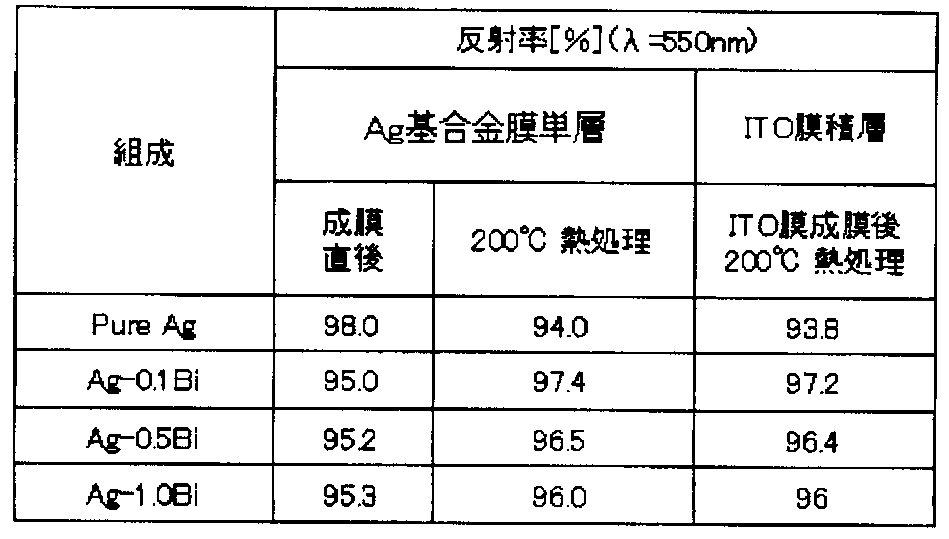
- Tables 3 and 4 show the reflectivity immediately after the formation of the Ag-based alloy film 6 and the reflectivity after the heat treatment at 200 ° C. after forming the Ag-based alloy film 6 for the samples of each composition of the C group. The result of having measured the reflectance after forming an ITO film
- the Ag-based alloy film retains a higher reflectance than the pure Ag film after the ITO film is formed and heat-treated at 200 ° C.
- the Ag— (X) Nd— (Y) Cu alloy and the Ag— (X) Bi alloy are both before and after the heat treatment as compared with pure Ag. High reflectivity. Therefore, in the actual device manufacturing process, even if a thermal history of 200 ° C. or higher is applied after the Ag-based alloy film 6 is formed, the Ag-based alloy film 6 is superior in surface smoothness to a pure Ag film. all right.
- the reflective anode electrode of the present invention it is possible to suppress the occurrence of dark spots due to pinholes due to the irregularities on the surface of the organic light emitting layer.
- the Ag-based alloy film 6 of the present invention has a reflectance equal to or higher than that of pure Ag, and even when ITO, which is a transparent conductive film, is laminated, the reflectance is deteriorated as in the case of pure Ag. Therefore, it does not cause a decrease in light emission luminance, which is a characteristic caused by reflectance.
- Example 2 Disc-shaped glass (Corning's non-alkali glass # 1737, diameter: 50 mm, thickness: 0.7 mm) is used as the material of the substrate 1, and the SiN film as the passivation film 3 is a substrate temperature: 280 ° C., thickness : A film was formed on the surface of the substrate 1 at 300 nm. Further, using a DC magnetron sputtering apparatus, the Ag-based alloy film 6 of Ag-0.1Bi-0.2Nd and the Ag-based alloy film 6 of Ag-0.1Bi-0.1Ge are passivated at a thickness of 1000 mm. A film was formed on the surface of the film 3.
- the film formation conditions at this time were as follows: substrate temperature: room temperature, Ar gas pressure: 1 to 3 mTorr, distance between electrodes: 55 mm, film formation rate: 7.0 to 8.0 nm / sec.
- the ultimate vacuum before the formation of the Ag-based alloy film 6 was 1.0 ⁇ 10 ⁇ 5 Torr or less.
- the sample on which the formation of the Ag-based alloy film 6 was completed was subjected to a heat treatment in an oxygen atmosphere at a heat treatment temperature of 250 ° C. and a heat treatment time of 1 hour.
- Table 5 shows the results of measuring the reflectance and the surface roughness (Ra) for the sample before the heat treatment and the sample after the heat treatment, respectively.
- the heat treatment time of 1 hour was selected as a sufficient time for the reflectance and the surface roughness to not change any more.
- the surface of the pure Ag film is very rough, but the surface of the Ag-based alloy film 6 to which Bi—Nd or Bi—Ge is added has a very high flatness.
- Example 3 Among the samples of Group A of Example 1, the material of the Ag-based alloy film 6 is an Ag— (X) Nd— (Y) Cu alloy (X: 0.7 atomic%, Y: 0.9 atomic%). About some, an environmental test (Aging Test) was conducted. The environmental test was performed by exposing the sample for 48 hours in an environment of a temperature of 80 ° C. and a humidity of 90%, and a change in surface roughness was observed by AFM measurement. FIG. 4 shows the result.
- the Ag-based alloy film of the present invention has higher surface smoothness immediately after film formation (as-depo) than pure Ag, and there is almost no change after the environmental test. It can be seen that the addition of Nd and Cu improves the aggregation resistance.
- an example of an Ag—Nd—Cu alloy was shown, but similar results were obtained with an Ag—Bi alloy.
- Example 4 in the reflective anode of the present invention, the same environmental test as in Example 3 was performed on the Ag-based alloy film 6 to examine the degree of decrease in the reflectance of the Ag-based alloy film 6 before and after the environmental test.
- an Ag— (X) Nd alloy (X: variously changed at 0.1 to 1.0 atomic%) formed by sputtering was used.
- FIG. 5 shows the result.
- the decrease in reflectance after the environmental test is suppressed by adding Nd to Ag as compared with pure Ag. It can be seen that the agglomeration can be suppressed. The effect increases as the Nd addition amount increases.
- an example of an Ag—Nd alloy was shown, but similar results can be obtained with an Ag—Nd—Cu alloy and an Ag—Bi alloy.
- Example 5 Disc-shaped glass (Corning's non-alkali glass # 1737, diameter: 50 mm, thickness: 0.7 mm) is used as a material for the substrate 1, and an Ag-based alloy having a thickness of 1000 mm (100 nm) is obtained by a DC magnetron sputtering apparatus. A film 6 was formed on the surface of the substrate 1.
- the compositions used in this example are (1) pure Ag (Pure-Ag), (2) pure Al, (3) Ag-0.9Pd-1.0Cu, (4) Ag-0.1Bi-0. 2Nd, (5) Ag-0.1Bi-0.1Ge (unit of composition is atomic%).
- the deposition conditions for the Ag-based alloy film 6 were as follows: substrate temperature: room temperature, Ar gas pressure: 1 to 3 mTorr, distance between electrodes: 55 mm, deposition rate: 7.0 to 8.0 nm / sec.
- the ultimate vacuum before the formation of the Ag-based alloy film 6 was 1.0 ⁇ 10 ⁇ 5 Torr or less.
- the samples on which the Ag-based alloy film 6 has been formed are divided into two groups (A, B), and only the samples of the B group are subjected to heat treatment temperature: 250 ° C., heat treatment time: 1 hour, in an oxygen atmosphere.
- heat treated. 6 and 7 are scanning electron microscope images (SEM images) obtained by observing the surface of the heat-treated sample at 6000 times.
- 6A is an observation image of pure Ag
- FIG. 6B is an observation image of Ag-0.9Pd-1.0Cu, which corresponds to a comparative example.
- FIG. 7A is an observation image of Ag-0.1Bi-0.2Nd
- FIG. 7B is an observation image of Ag-0.1Bi-0.1Ge, which corresponds to an example.
- Table 6 shows the electrical resistivity of the sample immediately after the formation of the Ag-based alloy film 6 (before the heat treatment) and the sample after the heat treatment, respectively. “Surface roughness” in Table 6 is a relative judgment from the photographs of FIGS. 6 and 7.
- the Ag—Pd—Cu alloy containing neither Nd nor Bi has an electric resistivity of 3.21 ⁇ ⁇ cm
- the Ag—Bi—Nd alloy and Ag—Bi It can be seen that the -Ge alloy has a lower electrical resistivity and can be used as a wiring film, as is the case with commonly used Al materials.
- pure Ag also shows a low electrical resistivity, as can be seen from the surface photograph of FIG. 6A, pure Ag has a large degree of aggregation of Ag, and if this progresses further, there is a risk of short circuiting or disconnection. Therefore, it cannot be used as a wiring film.
- Substrate 2 Thin film transistor (TFT) 3 Passivation film 4 Planarization layer 5 Contact hole 6 Ag-based alloy film 7 Oxide conductive film 8 Organic light emitting layer 9 Cathode electrode
Abstract
Description
円盤状のガラス(コーニング社の無アルカリガラス#1737、直径:50mm、厚さ:0.7mm)を基板1の材料として用い、パッシベーション膜3であるSiN膜を、基板温度:280℃、厚さ:300nmで成膜した。更に、DCマグネトロンスパッタリング装置を用いて、パッシベーション膜3の表面上に、厚さ1000ÅのAg-(X)Nd-(Y)CuのAg基合金膜6(X:0.2~0.7原子%、Y:0.3~0.9原子%)およびAg-(X)BiのAg基合金膜6(X:0.1~1.0原子%)薄膜を成膜した。このときの成膜条件は、基板温度:室温、Arガス圧:1~3mTorr、極間距離:55mm、成膜速度:7.0~8.0nm/secであった。また、Ag基合金膜6の成膜前の到達真空度は、1.0×10-5Torr以下であった。 Example 1
Disc-shaped glass (Corning's non-alkali glass # 1737, diameter: 50 mm, thickness: 0.7 mm) is used as the material of the


円盤状のガラス(コーニング社の無アルカリガラス#1737、直径:50mm、厚さ:0.7mm)を基板1の材料として用い、パッシベーション膜3であるSiN膜を、基板温度:280℃、厚さ:300nmで基板1の表面に成膜した。更に、DCマグネトロンスパッタリング装置を用いて、Ag-0.1Bi-0.2NdのAg基合金膜6、およびAg-0.1Bi-0.1GeのAg基合金膜6を、厚さ:1000Åでパッシベーション膜3の表面上に成膜した。このときの成膜条件は、基板温度:室温、Arガス圧:1~3mTorr、極間距離:55mm、成膜速度:7.0~8.0nm/secであった。また、Ag基合金膜6の成膜前の到達真空度は、1.0×10-5Torr以下であった。 (Example 2)
Disc-shaped glass (Corning's non-alkali glass # 1737, diameter: 50 mm, thickness: 0.7 mm) is used as the material of the

実施例1のAグループの試料の中から、Ag基合金膜6の材料がAg-(X)Nd-(Y)Cu合金(X:0.7原子%、Y:0.9原子%)であるものについて、環境試験(Aging Test)を行った。環境試験は、温度80℃、湿度90%の環境下に試料を48時間曝すことにより行い、AFM測定による表面粗さの変化を観察した。図4はその結果を示す。 (Example 3)
Among the samples of Group A of Example 1, the material of the Ag-based alloy film 6 is an Ag— (X) Nd— (Y) Cu alloy (X: 0.7 atomic%, Y: 0.9 atomic%). About some, an environmental test (Aging Test) was conducted. The environmental test was performed by exposing the sample for 48 hours in an environment of a temperature of 80 ° C. and a humidity of 90%, and a change in surface roughness was observed by AFM measurement. FIG. 4 shows the result.
次に、本発明の反射アノード電極において、Ag基合金膜6に対して、実施例3と同様の環境試験を行い、環境試験前後におけるAg基合金膜6の反射率の低下度合いを調べた。この試験には、Ag-(X)Nd合金(X:0.1~1.0原子%で種々変化)をスパッタ成膜したものを用いた。図5はその結果を示す。 Example 4
Next, in the reflective anode of the present invention, the same environmental test as in Example 3 was performed on the Ag-based alloy film 6 to examine the degree of decrease in the reflectance of the Ag-based alloy film 6 before and after the environmental test. In this test, an Ag— (X) Nd alloy (X: variously changed at 0.1 to 1.0 atomic%) formed by sputtering was used. FIG. 5 shows the result.
円盤状のガラス(コーニング社の無アルカリガラス#1737、直径:50mm、厚さ:0.7mm)を基板1の材料として用い、DCマグネトロンスパッタリング装置により、厚さ:1000Å(100nm)のAg基合金膜6を基板1の表面に成膜した。本実施例で用いた組成は、(1)純Ag(Pure-Ag)、(2)純Al、(3)Ag-0.9Pd-1.0Cu、(4)Ag-0.1Bi-0.2Nd、(5)Ag-0.1Bi-0.1Geである(組成の単位は原子%)。Ag基合金膜6の成膜条件は、基板温度:室温、Arガス圧:1~3mTorr、極間距離:55mm、成膜速度:7.0~8.0nm/secであった。また、Ag基合金膜6の成膜前の到達真空度は、1.0×10-5Torr以下であった。 (Example 5)
Disc-shaped glass (Corning's non-alkali glass # 1737, diameter: 50 mm, thickness: 0.7 mm) is used as a material for the

2 薄膜トランジスタ(TFT)
3 パッシベーション膜
4 平坦化層
5 コンタクトホール
6 Ag基合金膜
7 酸化物導電膜
8 有機発光層
9 カソード電極 1
3
Claims (20)
- 基板上に形成された有機ELディスプレイ用の反射アノード電極であって、
Ndを0.01~1.5原子%含有するAg基合金膜と、前記Ag基合金膜に直接接触する酸化物導電膜と、を含むことを特徴とする有機ELディスプレイ用の反射アノード電極。 A reflective anode electrode for an organic EL display formed on a substrate,
A reflective anode electrode for an organic EL display, comprising: an Ag-based alloy film containing 0.01 to 1.5 atomic% of Nd; and an oxide conductive film in direct contact with the Ag-based alloy film. - Ndの含有量が0.1~1.5原子%である請求項1に記載の有機ELディスプレイ用の反射アノード電極。 The reflective anode for an organic EL display according to claim 1, wherein the Nd content is 0.1 to 1.5 atomic%.
- 前記Ag基合金膜が、更に、Cu,Au,Pd,Bi,Geから選ばれる1種以上の元素を合計で0.01~1.5原子%含有する請求項1または2に記載の有機ELディスプレイ用の反射アノード電極。 3. The organic EL according to claim 1, wherein the Ag-based alloy film further contains 0.01 to 1.5 atomic% in total of one or more elements selected from Cu, Au, Pd, Bi, and Ge. Reflective anode electrode for display.
- 基板上に形成された有機ELディスプレイ用の反射アノード電極であって、
Biを0.01~4原子%含有するAg基合金膜と、前記Ag基合金膜に直接接触する酸化物導電膜と、を含むことを特徴とする有機ELディスプレイ用の反射アノード電極。 A reflective anode electrode for an organic EL display formed on a substrate,
A reflective anode electrode for an organic EL display, comprising: an Ag-based alloy film containing 0.01 to 4 atomic% of Bi; and an oxide conductive film in direct contact with the Ag-based alloy film. - 前記Ag基合金膜が、更に、Cu,Au,Pd,Geから選ばれる1種以上の元素を合計で0.01~1.5原子%含有する請求項4に記載の有機ELディスプレイ用の反射アノード電極。 5. The reflection for an organic EL display according to claim 4, wherein the Ag-based alloy film further contains a total of 0.01 to 1.5 atomic% of one or more elements selected from Cu, Au, Pd, and Ge. Anode electrode.
- 前記Ag基合金膜の表面の組成がBi2O3である請求項4または5に記載の有機ELディスプレイ用の反射アノード電極。 The reflective anode for an organic EL display according to claim 4 or 5, wherein the composition of the surface of the Ag-based alloy film is Bi 2 O 3 .
- 前記Ag基合金膜が、更に、希土類元素から選ばれる1種以上を合計で0.01~2原子%含有する請求項4または5に記載の反射アノード電極。 6. The reflective anode according to claim 4, wherein the Ag-based alloy film further contains 0.01 to 2 atomic% in total of one or more selected from rare earth elements.
- 前記Ag基合金膜が、更に、Ndおよび/またはYを合計で0.01~2原子%含有する請求項4または5に記載の反射アノード電極。 6. The reflective anode according to claim 4, wherein the Ag-based alloy film further contains 0.01 to 2 atomic% of Nd and / or Y in total.
- 前記Ag基合金膜が、Au,Cu,Pt,PdおよびRhよりなる群から選ばれる1種以上の元素を合計で3原子%以下(0原子%を含まない)含有する請求項4または5に記載の反射アノード電極。 6. The Ag-based alloy film according to claim 4 or 5, containing a total of 3 atomic% or less (excluding 0 atomic%) of one or more elements selected from the group consisting of Au, Cu, Pt, Pd and Rh. The reflective anode electrode as described.
- 前記Ag基合金膜表面の十点平均粗さRzが、20nm以下である請求項1または4に記載の反射アノード電極。 The reflective anode according to claim 1 or 4, wherein the 10-point average roughness Rz of the Ag-based alloy film surface is 20 nm or less.
- 前記Ag基合金膜が、スパッタリング法または真空蒸着法で形成される請求項1または4に記載の反射アノード電極。 The reflective anode electrode according to claim 1 or 4, wherein the Ag-based alloy film is formed by a sputtering method or a vacuum deposition method.
- 前記Ag基合金膜が、前記基板上に形成された薄膜トランジスタのソース/ドレイン電極に電気的に接続されている請求項1または4に記載の反射アノード電極を備えた薄膜トランジスタ基板。 The thin film transistor substrate provided with the reflective anode electrode according to claim 1 or 4, wherein the Ag-based alloy film is electrically connected to a source / drain electrode of the thin film transistor formed on the substrate.
- 請求項12に記載の薄膜トランジスタ基板を備えた有機ELディスプレイ。 An organic EL display comprising the thin film transistor substrate according to claim 12.
- 請求項1または4に記載の反射アノード電極を形成するためのスパッタリングターゲット。 A sputtering target for forming the reflective anode electrode according to claim 1 or 4.
- 基板上に形成された有機ELディスプレイ用の配線膜であって、
Ndを0.01~1.5原子%含有するAg基合金膜を少なくとも含むことを特徴とする有機ELディスプレイ用の配線膜。 A wiring film for an organic EL display formed on a substrate,
A wiring film for an organic EL display, comprising at least an Ag-based alloy film containing 0.01 to 1.5 atomic% of Nd. - Ndの含有量が0.1~1.5原子%である請求項15に記載の配線膜。 The wiring film according to claim 15, wherein the Nd content is 0.1 to 1.5 atomic%.
- 前記Ag基合金膜が、更に、Cu,Au,Pd,Bi,Geから選ばれる1種以上の元素を合計で0.01~1.5原子%含有する請求項15または16に記載の配線膜。 The wiring film according to claim 15 or 16, wherein the Ag-based alloy film further contains 0.01 to 1.5 atomic% in total of one or more elements selected from Cu, Au, Pd, Bi, and Ge. .
- 基板上に形成された有機ELディスプレイ用の配線膜であって、
Biを0.01~4原子%含有するAg基合金膜を少なくとも含むことを特徴とする有機ELディスプレイ用の配線膜。 A wiring film for an organic EL display formed on a substrate,
A wiring film for an organic EL display, comprising at least an Ag-based alloy film containing 0.01 to 4 atomic% of Bi. - 前記Ag基合金膜が、更に、Cu,Au,Pd,Geから選ばれる1種以上の元素を合計で0.01~1.5原子%含有する請求項18に記載の配線膜。 The wiring film according to claim 18, wherein the Ag-based alloy film further contains 0.01 to 1.5 atomic% in total of one or more elements selected from Cu, Au, Pd, and Ge.
- 請求項15または18に記載の配線膜を形成するためのスパッタリングターゲット。 A sputtering target for forming the wiring film according to claim 15 or 18.
Priority Applications (2)
| Application Number | Priority Date | Filing Date | Title |
|---|---|---|---|
| US13/128,415 US8431931B2 (en) | 2008-11-10 | 2009-11-09 | Reflective anode and wiring film for organic EL display device |
| CN2009801375990A CN102165846A (en) | 2008-11-10 | 2009-11-09 | Reflective anode and wiring film for organic el display device |
Applications Claiming Priority (6)
| Application Number | Priority Date | Filing Date | Title |
|---|---|---|---|
| JP2008288084 | 2008-11-10 | ||
| JP2008-288084 | 2008-11-10 | ||
| JP2009043409 | 2009-02-26 | ||
| JP2009-043409 | 2009-02-26 | ||
| JP2009-186075 | 2009-08-10 | ||
| JP2009186075A JP2010225572A (en) | 2008-11-10 | 2009-08-10 | Reflective anode and wiring film for organic el display device |
Publications (1)
| Publication Number | Publication Date |
|---|---|
| WO2010053183A1 true WO2010053183A1 (en) | 2010-05-14 |
Family
ID=42152988
Family Applications (1)
| Application Number | Title | Priority Date | Filing Date |
|---|---|---|---|
| PCT/JP2009/069068 WO2010053183A1 (en) | 2008-11-10 | 2009-11-09 | Reflective anode and wiring film for organic el display device |
Country Status (6)
| Country | Link |
|---|---|
| US (1) | US8431931B2 (en) |
| JP (1) | JP2010225572A (en) |
| KR (1) | KR20110082561A (en) |
| CN (1) | CN102165846A (en) |
| TW (1) | TW201038124A (en) |
| WO (1) | WO2010053183A1 (en) |
Cited By (1)
| Publication number | Priority date | Publication date | Assignee | Title |
|---|---|---|---|---|
| US20120097545A1 (en) * | 2010-05-20 | 2012-04-26 | Toru Imori | Silver electroplated and/or silver alloy electroplated article having an oxidation layer on its surface |
Families Citing this family (12)
| Publication number | Priority date | Publication date | Assignee | Title |
|---|---|---|---|---|
| JP5806653B2 (en) * | 2011-12-27 | 2015-11-10 | 株式会社神戸製鋼所 | Ag alloy film for reflective electrode, reflective electrode, and Ag alloy sputtering target |
| EP2629347A1 (en) * | 2012-02-17 | 2013-08-21 | Nederlandse Organisatie voor toegepast -natuurwetenschappelijk onderzoek TNO | Opto-electric device and method for manufacturing the same |
| JP2014047400A (en) * | 2012-08-31 | 2014-03-17 | Kobe Steel Ltd | Ag ALLOY MEMBRANE FOR SEMI-TRANSMISSIVE ELECTRODE OF FLAT PANEL DISPLAY, AND SEMI-TRANSMISSIVE ELECTRODE FOR FLAT PANEL DISPLAY |
| JP5985414B2 (en) * | 2013-02-19 | 2016-09-06 | デクセリアルズ株式会社 | Anisotropic conductive adhesive, light emitting device, and method of manufacturing anisotropic conductive adhesive |
| WO2014157581A1 (en) | 2013-03-29 | 2014-10-02 | トッパン・フォームズ株式会社 | Laminate and circuit board |
| WO2014208341A1 (en) | 2013-06-26 | 2014-12-31 | 株式会社神戸製鋼所 | Ag alloy film for reflecting electrode or wiring electrode, reflecting electrode or wiring electrode, and ag alloy sputtering target |
| JP6068425B2 (en) * | 2014-12-11 | 2017-01-25 | 株式会社神戸製鋼所 | Electrode structure |
| CN105810842B (en) * | 2014-12-29 | 2019-01-11 | 昆山国显光电有限公司 | The anode construction of Organic Light Emitting Diode |
| US10822692B2 (en) * | 2016-08-12 | 2020-11-03 | University Of North Texas | Binary Ag—Cu amorphous thin-films for electronic applications |
| JP2018032601A (en) * | 2016-08-26 | 2018-03-01 | 株式会社神戸製鋼所 | REFLECTION ELECTRODE AND Al ALLOY SPUTTERING TARGET |
| JP7053290B2 (en) * | 2018-02-05 | 2022-04-12 | 株式会社神戸製鋼所 | Reflective anode electrode for organic EL display |
| JP7231487B2 (en) * | 2019-05-30 | 2023-03-01 | 株式会社神戸製鋼所 | Reflective anode electrode and manufacturing method thereof, thin film transistor substrate, organic EL display, and sputtering target |
Citations (11)
| Publication number | Priority date | Publication date | Assignee | Title |
|---|---|---|---|---|
| JPH09274990A (en) * | 1996-04-08 | 1997-10-21 | Mitsubishi Chem Corp | Organic electroluminescence element, and its manufacture |
| JP2002323611A (en) * | 2001-02-21 | 2002-11-08 | Kobe Steel Ltd | Light-reflecting film, reflection type liquid crystal display element and sputtering target for light- reflecting film |
| JP2004333882A (en) * | 2003-05-08 | 2004-11-25 | Idemitsu Kosan Co Ltd | Reflection type electrode substrate and method of manufacturing the same |
| JP2004339585A (en) * | 2003-05-16 | 2004-12-02 | Kobe Steel Ltd | Ag-Bi-BASED ALLOY SPUTTERING TARGET AND MANUFACTURING METHOD THEREFOR |
| JP2005011792A (en) * | 2003-03-26 | 2005-01-13 | Sony Corp | Light emitting device, its manufacturing method, and display device |
| JP2005048231A (en) * | 2003-07-28 | 2005-02-24 | Ishifuku Metal Ind Co Ltd | Sputtering target material |
| JP2005187937A (en) * | 2003-12-04 | 2005-07-14 | Kobe Steel Ltd | Ag-based alloy wiring electrode film for flat panel display and ag-based alloy sputtering target, and flat panel display |
| JP2006037169A (en) * | 2004-07-27 | 2006-02-09 | Furuya Kinzoku:Kk | Silver alloy, sputtering target thereof and thin film thereby |
| JP2006070345A (en) * | 2004-09-03 | 2006-03-16 | Kobe Steel Ltd | Ag-BASED ALLOY WIRING ELECTRODE FILM AND Ag-BASE ALLOY SPUTTERING TARGET FOR FLAT PANEL DISPLAY, AND FLAT PANEL DISPLAY |
| JP2006310317A (en) * | 2005-04-28 | 2006-11-09 | Samsung Sdi Co Ltd | Organic electroluminescence element and method of fabricating the same |
| JP2008108533A (en) * | 2006-10-25 | 2008-05-08 | Canon Inc | Organic el display device |
Family Cites Families (64)
| Publication number | Priority date | Publication date | Assignee | Title |
|---|---|---|---|---|
| JPH0428032A (en) | 1990-05-24 | 1992-01-30 | Daicel Chem Ind Ltd | Optical information recording medium |
| JPH04252440A (en) | 1991-01-28 | 1992-09-08 | Hitachi Maxell Ltd | Optical information recording medium |
| JPH05258363A (en) | 1992-03-10 | 1993-10-08 | Sumitomo Metal Mining Co Ltd | Magneto-optical recording medium |
| US5948497A (en) * | 1992-10-19 | 1999-09-07 | Eastman Kodak Company | High stability silver based alloy reflectors for use in a writable compact disk |
| JPH06302027A (en) | 1993-04-15 | 1994-10-28 | Mitsubishi Materials Corp | Reflecting film for magneto-optical recording medium |
| JP3638152B2 (en) | 1996-09-09 | 2005-04-13 | 松下電器産業株式会社 | Optical information recording medium and manufacturing method thereof, optical information recording / reproducing method, and optical information recording / reproducing apparatus |
| US6905750B2 (en) * | 1998-06-22 | 2005-06-14 | Target Technology Company, Llc | Metal alloys for the reflective or the semi-reflective layer of an optical storage medium |
| US6544616B2 (en) * | 2000-07-21 | 2003-04-08 | Target Technology Company, Llc | Metal alloys for the reflective or the semi-reflective layer of an optical storage medium |
| US6764735B2 (en) * | 1998-06-22 | 2004-07-20 | Target Technology Company, Llc | Metal alloys for the reflective or the semi-reflective layer of an optical storage medium |
| US6790503B2 (en) * | 1998-06-22 | 2004-09-14 | Target Technology Company, Llc | Metal alloys for the reflective or the semi-reflective layer of an optical storage medium |
| US6451402B1 (en) * | 1998-06-22 | 2002-09-17 | Target Technology Company, Llc | Metal alloys for the reflective or the semi-reflective layer of an optical storage medium |
| US6852384B2 (en) * | 1998-06-22 | 2005-02-08 | Han H. Nee | Metal alloys for the reflective or the semi-reflective layer of an optical storage medium |
| US6007889A (en) * | 1998-06-22 | 1999-12-28 | Target Technology, Llc | Metal alloys for the reflective or the semi-reflective layer of an optical storage medium |
| US7045187B2 (en) * | 1998-06-22 | 2006-05-16 | Nee Han H | Metal alloys for the reflective or the semi-reflective layer of an optical storage medium |
| JP2000057627A (en) | 1998-08-04 | 2000-02-25 | Mitsui Chemicals Inc | Light-reflecting film and optical recording medium using the same |
| JP2001184725A (en) | 1999-12-21 | 2001-07-06 | Victor Co Of Japan Ltd | Optical information recording medium |
| SG116432A1 (en) * | 2000-12-26 | 2005-11-28 | Kobe Steel Ltd | Reflective layer or semi-transparent reflective layer for use in optical information recording media, optical information recording media and sputtering target for use in the optical information recording media. |
| JP2003098538A (en) * | 2001-09-20 | 2003-04-03 | Seiko Epson Corp | Electro-optical device and manufacturing method therefor |
| JP3772972B2 (en) | 2001-11-26 | 2006-05-10 | 三菱マテリアル株式会社 | Silver alloy sputtering target for reflection layer formation of optical recording media |
| KR100491931B1 (en) * | 2002-01-25 | 2005-05-30 | 가부시키가이샤 고베 세이코쇼 | Reflective film, reflection type liquid crystal display, and sputtering target for forming the reflective film |
| TWI258514B (en) * | 2002-06-24 | 2006-07-21 | Kobelco Res Inst Inc | Silver alloy sputtering target and process for producing the same |
| JP4062599B2 (en) * | 2002-07-29 | 2008-03-19 | 日立金属株式会社 | Ag alloy film for display device, flat display device, and sputtering target material for forming Ag alloy film |
| US7514037B2 (en) * | 2002-08-08 | 2009-04-07 | Kobe Steel, Ltd. | AG base alloy thin film and sputtering target for forming AG base alloy thin film |
| JP4105956B2 (en) | 2002-08-08 | 2008-06-25 | 株式会社神戸製鋼所 | Light reflection film, liquid crystal display device using the same, and sputtering target for light reflection film |
| JP2004158145A (en) | 2002-11-08 | 2004-06-03 | Tdk Corp | Optical recording medium |
| US20070037402A1 (en) * | 2003-02-05 | 2007-02-15 | Kazuyoshi Inoue | Method for manufacturing semi-transparent semi-reflective electrode substrate, reflective element substrate, method for manufacturing same, etching composition used for the method for manufacturing the reflective electrode substrate |
| JP2004253511A (en) * | 2003-02-19 | 2004-09-09 | Hitachi Displays Ltd | Display apparatus |
| JP4181490B2 (en) * | 2003-03-25 | 2008-11-12 | 松下電器産業株式会社 | Information recording medium and manufacturing method thereof |
| JP2006523913A (en) * | 2003-04-18 | 2006-10-19 | ターゲット・テクノロジー・カンパニー・エルエルシー | Alloys for reflective or semi-reflective layers of light storage media |
| JP4009564B2 (en) * | 2003-06-27 | 2007-11-14 | 株式会社神戸製鋼所 | Ag alloy reflective film for reflector, reflector using this Ag alloy reflective film, and Ag alloy sputtering target for forming an Ag alloy thin film of this Ag alloy reflective film |
| JP2005029849A (en) * | 2003-07-07 | 2005-02-03 | Kobe Steel Ltd | Ag ALLOY REFLECTIVE FILM FOR REFLECTOR, REFLECTOR USING THE Ag ALLOY REFLECTIVE FILM, AND Ag ALLOY SPUTTERING TARGET FOR DEPOSITING THE Ag ALLOY REFLECTIVE FILM |
| US20050019203A1 (en) * | 2003-07-23 | 2005-01-27 | Yuhichi Saitoh | Silver alloy material, circuit substrate, electronic device, and method for manufacturing circuit substrate |
| JP4421394B2 (en) | 2003-07-23 | 2010-02-24 | シャープ株式会社 | Silver alloy material, circuit board, electronic device, and method of manufacturing circuit board |
| US20050112019A1 (en) * | 2003-10-30 | 2005-05-26 | Kabushiki Kaisha Kobe Seiko Sho(Kobe Steel, Ltd.) | Aluminum-alloy reflection film for optical information-recording, optical information-recording medium, and aluminum-alloy sputtering target for formation of the aluminum-alloy reflection film for optical information-recording |
| CN100334239C (en) * | 2003-12-04 | 2007-08-29 | 株式会社神户制钢所 | Ag-base alloy distribution electrode film, Ag-base alloy sputtering target for panel display |
| JP4252440B2 (en) | 2003-12-22 | 2009-04-08 | エヌ・ティ・ティ・コムウェア株式会社 | Exhibit commentary system, exhibit commentary information management server, and exhibit commentary method |
| KR100579192B1 (en) | 2004-03-11 | 2006-05-11 | 삼성에스디아이 주식회사 | Top-emission type organic electro luminescence display device and method for fabricating of the same |
| JP2005275102A (en) * | 2004-03-25 | 2005-10-06 | Nec Lcd Technologies Ltd | Translucent type liquid crystal display device and manufacturing method therefor |
| TWI325134B (en) * | 2004-04-21 | 2010-05-21 | Kobe Steel Ltd | Semi-reflective film and reflective film for optical information recording medium, optical information recording medium, and sputtering target |
| JP4918231B2 (en) | 2004-06-16 | 2012-04-18 | 株式会社アルバック | Method for producing Ag alloy film |
| ATE379836T1 (en) * | 2004-06-29 | 2007-12-15 | Kobe Steel Ltd | SEMI-REFLECTIVE AND REFLECTIVE LAYER FOR AN OPTICAL INFORMATION RECORDING MEDIUM, INFORMATION RECORDING MEDIUM, AND SPUTTER TARGET |
| JP3907666B2 (en) * | 2004-07-15 | 2007-04-18 | 株式会社神戸製鋼所 | Read-only optical information recording medium for laser marking |
| JP2006240289A (en) * | 2005-02-07 | 2006-09-14 | Kobe Steel Ltd | Recording film for optical information recording medium, optical information recording medium and sputtering target |
| CN101156203B (en) * | 2005-04-07 | 2010-09-15 | 三菱化学媒体股份有限公司 | Optical recording medium |
| JP2006294195A (en) * | 2005-04-14 | 2006-10-26 | Kobe Steel Ltd | Ag alloy reflection film for optical information recording, optical information recording medium and ag alloy sputtering target for deposition of ag alloy reflection film for optical information recording |
| US7687986B2 (en) * | 2005-05-27 | 2010-03-30 | Fujifilm Corporation | Organic EL device having hole-injection layer doped with metallic oxide |
| JP2007035104A (en) * | 2005-07-22 | 2007-02-08 | Kobe Steel Ltd | Ag ALLOY REFLECTION FILM FOR OPTICAL INFORMATION RECORDING MEDIUM, OPTICAL INFORMATION RECORDING MEDIUM AND Ag ALLOY SPUTTERING TARGET FOR FORMING Ag ALLOY REFLECTION FILM FOR OPTICAL INFORMATION RECORDING MEDIUM |
| JP4377861B2 (en) * | 2005-07-22 | 2009-12-02 | 株式会社神戸製鋼所 | Ag alloy reflecting film for optical information recording medium, optical information recording medium, and Ag alloy sputtering target for forming Ag alloy reflecting film for optical information recording medium |
| JP4527624B2 (en) * | 2005-07-22 | 2010-08-18 | 株式会社神戸製鋼所 | Optical information medium having Ag alloy reflective film |
| JP4377877B2 (en) * | 2005-12-21 | 2009-12-02 | ソニー株式会社 | Ag alloy reflecting film for optical information recording medium, optical information recording medium, and Ag alloy sputtering target for forming Ag alloy reflecting film for optical information recording medium |
| JP5241128B2 (en) * | 2006-04-26 | 2013-07-17 | キヤノン株式会社 | Multicolor display device |
| JP2007335061A (en) * | 2006-05-16 | 2007-12-27 | Sony Corp | Optical information recording medium and its burst cutting area marking method |
| JP2008016074A (en) * | 2006-06-30 | 2008-01-24 | Toshiba Corp | Write-once type information recording medium and disk drive |
| JP2008077792A (en) * | 2006-09-22 | 2008-04-03 | Kobe Steel Ltd | Optical information recording medium with excellent durability |
| JP2008117470A (en) * | 2006-11-02 | 2008-05-22 | Sony Corp | Optical information recording medium and method for manufacturing optical information recording medium, bca (burst cutting area) marking method |
| JP2008156753A (en) * | 2006-12-01 | 2008-07-10 | Kobe Steel Ltd | Ag ALLOY REFLECTIVE LAYER FOR OPTICAL INFORMATION RECORDING MEDIUM, OPTICAL INFORMATION RECORDING MEDIUM, AND SPUTTERING TARGET FOR FORMING Ag ALLOY REFLECTIVE LAYER FOR OPTICAL INFORMATION RECORDING MEDIUM |
| US8367200B2 (en) * | 2007-01-11 | 2013-02-05 | Kobe Steel, Ltd. | Reflecting film excellent in cohesion resistance and sulfur resistance |
| JP2008210665A (en) * | 2007-02-27 | 2008-09-11 | Canon Inc | Organic light-emitting element, and display device using the same |
| JP2008276212A (en) * | 2007-04-05 | 2008-11-13 | Fujifilm Corp | Organic electroluminescent display device |
| JP4694543B2 (en) * | 2007-08-29 | 2011-06-08 | 株式会社コベルコ科研 | Ag-based alloy sputtering target and manufacturing method thereof |
| JP4833942B2 (en) * | 2007-08-29 | 2011-12-07 | 株式会社コベルコ科研 | Ag-based alloy sputtering target |
| JP2009076129A (en) * | 2007-09-19 | 2009-04-09 | Kobe Steel Ltd | Read-only optical information recording medium |
| JP5046890B2 (en) * | 2007-11-29 | 2012-10-10 | 株式会社コベルコ科研 | Ag-based sputtering target |
| JP2009187642A (en) * | 2008-02-08 | 2009-08-20 | Kobe Steel Ltd | Reflective film and semi-transmissive reflective film of optical information recording medium, sputtering target for producing the films, and optical information recording medium |
-
2009
- 2009-08-10 JP JP2009186075A patent/JP2010225572A/en active Pending
- 2009-11-09 US US13/128,415 patent/US8431931B2/en not_active Expired - Fee Related
- 2009-11-09 WO PCT/JP2009/069068 patent/WO2010053183A1/en active Application Filing
- 2009-11-09 CN CN2009801375990A patent/CN102165846A/en active Pending
- 2009-11-09 KR KR1020117010537A patent/KR20110082561A/en not_active Application Discontinuation
- 2009-11-10 TW TW98138071A patent/TW201038124A/en unknown
Patent Citations (11)
| Publication number | Priority date | Publication date | Assignee | Title |
|---|---|---|---|---|
| JPH09274990A (en) * | 1996-04-08 | 1997-10-21 | Mitsubishi Chem Corp | Organic electroluminescence element, and its manufacture |
| JP2002323611A (en) * | 2001-02-21 | 2002-11-08 | Kobe Steel Ltd | Light-reflecting film, reflection type liquid crystal display element and sputtering target for light- reflecting film |
| JP2005011792A (en) * | 2003-03-26 | 2005-01-13 | Sony Corp | Light emitting device, its manufacturing method, and display device |
| JP2004333882A (en) * | 2003-05-08 | 2004-11-25 | Idemitsu Kosan Co Ltd | Reflection type electrode substrate and method of manufacturing the same |
| JP2004339585A (en) * | 2003-05-16 | 2004-12-02 | Kobe Steel Ltd | Ag-Bi-BASED ALLOY SPUTTERING TARGET AND MANUFACTURING METHOD THEREFOR |
| JP2005048231A (en) * | 2003-07-28 | 2005-02-24 | Ishifuku Metal Ind Co Ltd | Sputtering target material |
| JP2005187937A (en) * | 2003-12-04 | 2005-07-14 | Kobe Steel Ltd | Ag-based alloy wiring electrode film for flat panel display and ag-based alloy sputtering target, and flat panel display |
| JP2006037169A (en) * | 2004-07-27 | 2006-02-09 | Furuya Kinzoku:Kk | Silver alloy, sputtering target thereof and thin film thereby |
| JP2006070345A (en) * | 2004-09-03 | 2006-03-16 | Kobe Steel Ltd | Ag-BASED ALLOY WIRING ELECTRODE FILM AND Ag-BASE ALLOY SPUTTERING TARGET FOR FLAT PANEL DISPLAY, AND FLAT PANEL DISPLAY |
| JP2006310317A (en) * | 2005-04-28 | 2006-11-09 | Samsung Sdi Co Ltd | Organic electroluminescence element and method of fabricating the same |
| JP2008108533A (en) * | 2006-10-25 | 2008-05-08 | Canon Inc | Organic el display device |
Cited By (1)
| Publication number | Priority date | Publication date | Assignee | Title |
|---|---|---|---|---|
| US20120097545A1 (en) * | 2010-05-20 | 2012-04-26 | Toru Imori | Silver electroplated and/or silver alloy electroplated article having an oxidation layer on its surface |
Also Published As
| Publication number | Publication date |
|---|---|
| KR20110082561A (en) | 2011-07-19 |
| US8431931B2 (en) | 2013-04-30 |
| CN102165846A (en) | 2011-08-24 |
| TW201038124A (en) | 2010-10-16 |
| JP2010225572A (en) | 2010-10-07 |
| US20110220903A1 (en) | 2011-09-15 |
Similar Documents
| Publication | Publication Date | Title |
|---|---|---|
| WO2010053183A1 (en) | Reflective anode and wiring film for organic el display device | |
| WO2010053184A1 (en) | Organic el display device reflective anode and method for manufacturing the same | |
| KR100802879B1 (en) | Display device | |
| US20120199866A1 (en) | Reflective anode electrode for organic el display | |
| US20060011914A1 (en) | Novel conductive elements for thin film transistors used in a flat panel display | |
| US20050285109A1 (en) | Novel conductive elements for thin film transistors used in a flat panel display | |
| JP2010225586A (en) | Reflective anode and wiring film for organic el display device | |
| WO2014080933A1 (en) | Electrode used in display device or input device, and sputtering target for use in electrode formation | |
| CN112018260B (en) | Reflective anode electrode, thin film transistor, organic EL display, and sputtering target | |
| WO2012161139A1 (en) | Wiring structure comprising reflective anode electrode for organic el displays | |
| JP2014120487A (en) | Electrode for use in display device or input device, and sputtering target for electrode formation | |
| JP2012243742A (en) | Wiring structure including organic el display reflective anode electrode | |
| JP6023404B2 (en) | Manufacturing method of wiring structure including reflective anode electrode for organic EL display | |
| JP4264397B2 (en) | Ag-based alloy wiring electrode film for flat panel display, Ag-based alloy sputtering target, and flat panel display | |
| JP2014120486A (en) | Electrode for use in display device or input device, and sputtering target for electrode formation | |
| JP2014103312A (en) | Electrode for use in display device or input device, and sputtering gate for forming electrode | |
| JP2012059470A (en) | Reflecting anodic electrode for organic el display | |
| WO2014038560A1 (en) | Organic el element, production method for reflective electrode in organic el element, and al alloy sputtering target for forming reflective electrode in organic el element | |
| JP2012243740A (en) | Wiring structure including organic el display reflective anode electrode | |
| JP2005276610A (en) | Manufacturing method of transparent conductive film |
Legal Events
| Date | Code | Title | Description |
|---|---|---|---|
| WWE | Wipo information: entry into national phase |
Ref document number: 200980137599.0 Country of ref document: CN |
|
| 121 | Ep: the epo has been informed by wipo that ep was designated in this application |
Ref document number: 09824880 Country of ref document: EP Kind code of ref document: A1 |
|
| ENP | Entry into the national phase |
Ref document number: 20117010537 Country of ref document: KR Kind code of ref document: A |
|
| NENP | Non-entry into the national phase |
Ref country code: DE |
|
| WWE | Wipo information: entry into national phase |
Ref document number: 13128415 Country of ref document: US |
|
| 122 | Ep: pct application non-entry in european phase |
Ref document number: 09824880 Country of ref document: EP Kind code of ref document: A1 |