WO2010053031A1 - Linear actuator - Google Patents
Linear actuator Download PDFInfo
- Publication number
- WO2010053031A1 WO2010053031A1 PCT/JP2009/068511 JP2009068511W WO2010053031A1 WO 2010053031 A1 WO2010053031 A1 WO 2010053031A1 JP 2009068511 W JP2009068511 W JP 2009068511W WO 2010053031 A1 WO2010053031 A1 WO 2010053031A1
- Authority
- WO
- WIPO (PCT)
- Prior art keywords
- central axis
- permanent magnets
- linear actuator
- magnetic flux
- magnet
- Prior art date
Links
Images


Classifications
-
- H—ELECTRICITY
- H02—GENERATION; CONVERSION OR DISTRIBUTION OF ELECTRIC POWER
- H02K—DYNAMO-ELECTRIC MACHINES
- H02K41/00—Propulsion systems in which a rigid body is moved along a path due to dynamo-electric interaction between the body and a magnetic field travelling along the path
- H02K41/02—Linear motors; Sectional motors
- H02K41/03—Synchronous motors; Motors moving step by step; Reluctance motors
- H02K41/031—Synchronous motors; Motors moving step by step; Reluctance motors of the permanent magnet type
-
- H—ELECTRICITY
- H02—GENERATION; CONVERSION OR DISTRIBUTION OF ELECTRIC POWER
- H02K—DYNAMO-ELECTRIC MACHINES
- H02K1/00—Details of the magnetic circuit
- H02K1/06—Details of the magnetic circuit characterised by the shape, form or construction
- H02K1/22—Rotating parts of the magnetic circuit
- H02K1/27—Rotor cores with permanent magnets
- H02K1/2706—Inner rotors
- H02K1/2713—Inner rotors the magnetisation axis of the magnets being axial, e.g. claw-pole type
-
- H—ELECTRICITY
- H02—GENERATION; CONVERSION OR DISTRIBUTION OF ELECTRIC POWER
- H02K—DYNAMO-ELECTRIC MACHINES
- H02K1/00—Details of the magnetic circuit
- H02K1/06—Details of the magnetic circuit characterised by the shape, form or construction
- H02K1/22—Rotating parts of the magnetic circuit
- H02K1/27—Rotor cores with permanent magnets
- H02K1/2706—Inner rotors
- H02K1/272—Inner rotors the magnetisation axis of the magnets being perpendicular to the rotor axis
- H02K1/2726—Inner rotors the magnetisation axis of the magnets being perpendicular to the rotor axis the rotor consisting of a single magnet or two or more axially juxtaposed single magnets
-
- H—ELECTRICITY
- H02—GENERATION; CONVERSION OR DISTRIBUTION OF ELECTRIC POWER
- H02K—DYNAMO-ELECTRIC MACHINES
- H02K2207/00—Specific aspects not provided for in the other groups of this subclass relating to arrangements for handling mechanical energy
- H02K2207/03—Tubular motors, i.e. rotary motors mounted inside a tube, e.g. for blinds
Definitions
- the present invention relates to a linear actuator, and more particularly to a linear actuator using the principle of a linear synchronous motor.
- a linear synchronous motor which is a linear motor that uses the attractive force and repulsive force between magnetic poles of a magnet, is known.
- One type of linear synchronous motor is a shaft motor.
- a shaft motor is disclosed on the homepage of DMC Hillstone Co., Ltd. (http://www.ghc.co.jp/product/shaft.html).
- FIG. 1 is a schematic diagram showing the configuration of the shaft motor.
- the shaft motor 101 includes a shaft portion 102 and a coil portion 103.
- the shaft portion 102 includes a plurality of permanent magnets 111 and an outer cylinder 114.
- the plurality of permanent magnets 111 are arranged along the central axis C such that the magnetic direction is opposite to the direction of the central axis C. That is, the north poles and the south poles are joined along the central axis C. Therefore, strong magnetic field lines are generated from the joint 112.
- the outer cylinder 114 is a cylinder that integrally stores a plurality of permanent magnets 111.
- the coil unit 103 includes a coil 118.
- the coil 118 has a common central axis and includes a plurality of coils 118 (for example, for U phase, for V phase, and for W phase) through which alternating currents having different phases flow.
- the shaft portion 102 passes through the inside of the plurality of coils 118.
- a current flows through the plurality of coils 118 surrounding the shaft portion 102, a magnetic field is generated, and thrust is generated according to Fleming's left-hand rule.
- the coil portion 103 moves linearly along the central axis C by this thrust.
- This shaft motor 101 is characterized in that no attracting force acts between the coil 118 and the shaft portion 102, and that the magnetic flux of the magnet 111 can be effectively utilized all around the magnet 111 without waste and has high thrust.
- the shaft motor can be used as a mechanical element that replaces the ball screw or as a linear actuator as one of the actuators by utilizing its function and characteristics.
- a linear synchronous motor is disclosed in Japanese Patent Application Laid-Open No. 2003-70226.
- This linear synchronous motor includes a primary side mover having a coil and a secondary side stator in which a plurality of permanent magnets are arranged along a straight line, and energizing the coil makes the mover a secondary side stator. Move along a straight line.
- a plurality of permanent magnets are arranged adjacent to each other, and the magnetization directions of the adjacent permanent magnets are varied by 90 degrees in the moving direction and the perpendicular direction of the mover.
- Japanese Patent Application Laid-Open No. 2007-6545 discloses a periodic magnetic field generator and a linear motor, a rotary motor, and a swing motor using the same.
- This periodic magnetic field generator has a Halbach array field pole composed of a main magnetic pole permanent magnet magnetized in the direction of the generated magnetic field and a sub magnetic pole permanent magnet magnetized differently from the magnetic pole direction of the main magnetic pole permanent magnet. I have. In this periodic magnetic field generator, a part of the main pole permanent magnet on the magnetic field generation side is replaced with a soft magnetic material.
- the shaft motor 101 is considered to have the following problems.
- the first problem is that the magnets 111 facing each other are arranged in direct contact with each other, so that the opposing magnets 111 weaken each other's magnetic field. That is, the operating point of the magnet in the vicinity of the contact surface changes due to the influence of the magnetic field generated by the adjacent magnet, and the performance of the magnet is not sufficiently exhibited.
- the magnetic flux on the contact surface of the magnet 111 must pass through the magnets 111 on both sides of the contact surface, and the magnitude of the magnetic flux is limited by the saturation magnetic flux density of the magnet 111. End up. Therefore, it is considered that the strength of the magnetic force of each magnet 111 cannot be fully utilized.
- the third problem is that since the magnets 111 are arranged to face each other, the adjacent magnets 111 repel each other and are difficult to assemble. In particular, it is necessary to increase the magnetic force of the magnet 111 in order to improve the thrust, but it is expected that assembly will become increasingly difficult.
- the fourth problem is that in order to fix the magnet 111, a tube-shaped outer cylinder 114 that houses the magnet 111 is essential. Therefore, due to the presence of the outer cylinder 114, the gap between the coil 118 and the magnet 111 increases, and the thrust decreases.
- An object of the present invention is to provide a linear actuator that can fully utilize the magnetic force of a magnet. Another object of the present invention is to provide a linear actuator that can be easily assembled. Still another object of the present invention is to provide a linear actuator capable of reducing the gap between the coil and the magnet and improving the thrust.
- the linear actuator of the present invention includes a coil portion and a shaft portion.
- the coil unit includes a plurality of coils through which alternating currents having different phases flow.
- the shaft portion passes through the inside of the plurality of coils.
- the shaft portion includes a plurality of permanent magnets and a plurality of intermediate members.
- the plurality of permanent magnets are arranged along the central axis such that the magnetization direction is opposite to the direction of the central axis.
- the plurality of intermediate members are disposed between each of the plurality of permanent magnets.
- the saturation magnetic flux density of each of the plurality of intermediate members is greater than the saturation magnetic flux density of each of the plurality of permanent magnets.
- a soft magnetic material having a saturation magnetic flux density higher than that of the permanent magnet is inserted as an intermediate member between the opposing permanent magnets. Due to the property that the saturation magnetic flux density of the intermediate member is larger than the saturation magnetic flux density of the permanent magnet, the magnetic flux between the opposing permanent magnets is higher than that in the case where the intermediate member is composed of only the permanent magnet, Both can pass through the intermediate member in a direction substantially perpendicular to the central axis, or can enter from the same direction. Thereby, the magnetic flux density in the position of the coil part can be increased. That is, since the opposing magnets do not weaken each other's magnetic field, the strength of the magnetic force of each magnet can be fully utilized. Thereby, the thrust of the linear actuator can be increased. Further, by interposing this intermediate member, the force with which the adjacent magnets repel each other can be weakened. Thereby, the assembly of a shaft part can be made easy. That is, it becomes possible to easily manufacture the linear actuator.
- the intermediate member since a soft magnetic material is used as the intermediate member, magnetic saturation due to concentration of magnetic flux between the opposing permanent magnets can be prevented at a low cost. Therefore, the thrust of the linear actuator can be improved at a low cost.
- each of the plurality of intermediate members includes an intermediate magnet member formed of a magnet material.
- the intermediate magnet members are alternately arranged along the central axis so that the magnetization direction is perpendicular outward and perpendicular inward to the direction of the central axis.
- the magnetic force of the intermediate portion is further applied without weakening the magnetic field between the opposing permanent magnets. Can increase the magnetic flux density. As a result, the thrust of the linear actuator can be increased.
- the thickness in the central axis direction of each of the plurality of intermediate members is preferably thinner than the thickness in the central axis direction of each of the plurality of permanent magnets.
- the thrust of the linear actuator can be increased by making the thickness of the intermediate member thinner than the thickness of the permanent magnet.
- each of the plurality of intermediate members preferably further includes a yoke member that surrounds the intermediate magnet member and is formed of a soft magnetic material.
- a soft magnetic material and a magnet material are used in combination as the intermediate member. Therefore, while preventing magnetic saturation due to the concentration of the magnetic flux between the opposing permanent magnets, the volume of the magnet can be increased to increase the magnetic flux density, and part of the material can be made of a hardly magnetic material to keep the cost low. Thereby, the magnetic flux density in a coil part can be raised more at low cost. As a result, the thrust of the linear actuator can be increased while suppressing the cost.
- each of the plurality of intermediate members has a thickness in the central axis direction that increases with distance from the central axis.
- the thickness of the intermediate member near the central axis where the degree of magnetic flux crowding is relatively small is reduced, and the thickness near the surface where the concentration of magnetic flux is relatively large is increased.
- production of the magnetic saturation by the concentration of the magnetic flux in an intermediate member can be reduced.
- the magnetic flux density in the coil portion can be further increased.
- the thrust of the linear actuator can be increased.
- the shaft portion further includes a fixed shaft member that penetrates and fixes the plurality of permanent magnets and the plurality of intermediate members.
- the tube-shaped outer cylinder for fixing a permanent magnet is unnecessary. Therefore, the gap between the coil and the magnet can be further reduced. Thereby, the magnetic flux density in a coil part can be raised more and the thrust of a linear actuator can be increased.
- the shaft portion and the coil portion preferably have a polygonal cross-sectional shape perpendicular to the central axis.
- the cross-sectional shape is a polygon, the coil portion is difficult to rotate in the circumferential direction. Therefore, the coil portion can be smoothly operated in the central axis direction.
- the magnetic force of the magnet can be fully utilized in the linear actuator.
- the linear actuator can be easily assembled.
- the gap between the coil and the magnet can be reduced and the thrust can be improved.
- FIG. 1 is a schematic view showing the configuration of a shaft motor of GM Hillstone Co., Ltd.
- FIG. 2A is a schematic perspective view showing the configuration of the linear actuator according to the first and second embodiments of the present invention.
- FIG. 2B is a schematic perspective view showing the configuration of the linear actuator according to the first and second embodiments of the present invention.
- FIG. 3A is a schematic cross-sectional view showing an example of a specific configuration of the intermediate member according to the first embodiment of the present invention.
- FIG. 3B is a schematic cross-sectional view showing an example of a specific configuration of the intermediate member according to the first embodiment of the present invention.
- FIG. 4A is a schematic cross-sectional view showing another example of the specific configuration of the intermediate member according to the first embodiment of the present invention.
- FIG. 4B is a schematic cross-sectional view showing another example of the specific configuration of the intermediate member according to the first embodiment of the present invention.
- FIG. 5A is a schematic cross-sectional view showing still another example of the specific configuration of the intermediate member according to the first embodiment of the present invention.
- FIG. 5B is a schematic cross-sectional view showing still another example of the specific configuration of the intermediate member according to the first embodiment of the present invention.
- FIG. 6A is a schematic cross-sectional view showing an example of a specific configuration of the intermediate member according to the second embodiment of the present invention.
- FIG. 6B is a schematic cross-sectional view showing an example of a specific configuration of the intermediate member according to the second embodiment of the present invention.
- FIG. 6C is a schematic cross-sectional view showing an example of a specific configuration of the intermediate member according to the second embodiment of the present invention.
- FIG. 6D is a schematic cross-sectional view showing an example of a specific configuration of the intermediate member according to the second embodiment of the present invention.
- FIG. 7A is a schematic cross-sectional view showing another example of the specific configuration of the intermediate member according to the second embodiment of the present invention.
- FIG. 7B is a schematic cross-sectional view showing another example of the specific configuration of the intermediate member according to the second embodiment of the present invention.
- FIG. 7C is a schematic cross-sectional view showing another example of the specific configuration of the intermediate member according to the second exemplary embodiment of the present invention.
- FIG. 8 is a schematic cross-sectional view showing the relationship in size between the intermediate member and the permanent magnet according to the second embodiment of the present invention.
- FIG. 9 is a schematic cross-sectional view showing still another example of the specific configuration of the intermediate member according to the second embodiment of the present invention.
- FIG. 10 is a schematic perspective view showing the configuration of the linear actuator according to the third embodiment of the present invention.
- FIG. 11 is a schematic plan view showing configurations of a permanent magnet and an intermediate member according to the third embodiment of the present invention.
- FIG. 12 is a schematic perspective view showing a modification of the configuration of the linear actuator according to the first to third embodiments of the present invention.
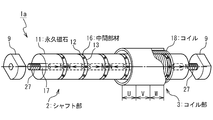
- the shaft motor 1 includes a shaft portion 2 and a coil portion 3.
- the shape of the shaft portion 2 is a rod shape, for example, a columnar shape.
- the shape of the coil part 3 is cylindrical, for example, cylindrical.
- the shaft portion 2 is disposed so as to pass inside the coil portion 3.
- the central axes of the shaft portion 2 and the coil portion 3 are substantially overlapped (hereinafter, the central axis C). And by passing an electric current through the coil part 3, the coil part 3 moves relatively on the shaft part 2 in the direction of the central axis C.
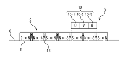
- the shaft portion 2 includes a plurality of permanent magnets 11, a plurality of intermediate members 16, and an outer cylinder 14.
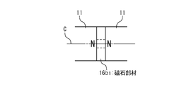
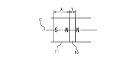
- the plurality of permanent magnets 11 are arranged along the central axis C such that the magnetization direction is opposite to the direction of the central axis C. That is, along the central axis C, the N poles and the S poles are arranged facing each other.
- the permanent magnet 11 has, for example, a substantially cylindrical shape.
- the central axis is the central axis C.
- various kinds of conventionally known permanent magnets can be used, for example, a ferrite magnet or a rare earth magnet.
- the intermediate member 16 is disposed between two adjacent permanent magnets 11. That is, it is sandwiched between two N poles or two S poles.
- the intermediate member 11 has, for example, a substantially cylindrical shape.
- the central axis is the central axis C.
- the saturation magnetic flux density of the intermediate member 16 is larger than the saturation magnetic flux density of the permanent magnet 11. Therefore, the magnetic flux emitted from these two N poles can pass through the inside of the intermediate member 16 sandwiched between the two N poles instead of the permanent magnet 11 and penetrate to the outside. Further, the magnetic fluxes directed to the two S poles can pass through the inside of the intermediate member 16 sandwiched between the two S poles instead of the permanent magnet 11 and penetrate inside.
- the outer cylinder 14 is provided outside the plurality of permanent magnets 11 and the plurality of intermediate members 16 so as to surround (store) them. That is, the outer cylinder 14 has a substantially cylindrical shape.
- the central axis is the central axis C.
- the outer cylinder 14 is made of a nonmagnetic material.
- the coil unit 3 includes a plurality of coils 18.
- the plurality of coils 18 are disposed adjacent to each other along the central axis C so as to surround the shaft portion 2 and not to contact the shaft portion 2.
- the coil 18 is wound in a substantially cylindrical shape.
- the central axis is the central axis C.
- the plurality of coils 18 are supplied with alternating currents having different phases.
- a three-phase coil 18, that is, a U-phase coil 18-1, a V-phase coil 18-2, and a W-phase coil 18-3 An alternating current having a phase shift of (2 ⁇ / 3) is applied.
- a set of U-phase coil 18-1 / V-phase coil 18-2 corresponding to one cycle of permanent magnet 11 / intermediate member 16 / permanent magnet 11 / intermediate member 16 A / W-phase coil 18-3 is provided.
- the shaft portion 2 passes through the inside of the plurality of coils 18.
- the magnetic force lines indicated by the outward arrows pass through the intermediate member 16 between the two N poles, and the magnetic force lines indicated by the inward arrows pass through the intermediate member 16 between the two S poles.
- thrust is generated according to Fleming's left-hand rule between components perpendicular to the axis of the magnetic field generated by the shaft portion. By this thrust, the coil part 3 moves relatively linearly on the shaft part 2 along the central axis C.
- the intermediate member 16 is inserted between the permanent magnets 11 facing each other.
- the saturation magnetic flux density of the intermediate member 16 is larger than the saturation magnetic flux density of the permanent magnet 11. Therefore, the magnetic fluxes between the opposing permanent magnets 11 are not limited to the saturation magnetic flux density of the permanent magnets 11, and both pass mainly through the intermediate member 16 without causing magnetic saturation in the intermediate member 16. It is possible to exit in a direction substantially perpendicular to the central axis C, or to enter from a direction substantially perpendicular to the central axis C. Thereby, the magnetic flux density in the position of the coil part 3 can be increased. Further, since the opposing magnets 11 do not weaken each other's magnetic field, the strength of the magnetic force of each magnet 11 can be fully utilized. Thereby, the thrust of the linear actuator can be increased.
- the force with which the adjacent permanent magnets 11 repel each other can be weakened.
- the N poles and the S poles can be easily coupled to face each other. That is, it is possible to facilitate the assembly of the shaft portion 2 by sandwiching the intermediate member 16 therebetween, and to facilitate the production of the linear actuator.
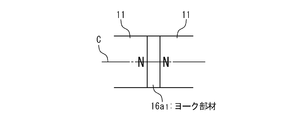
- FIG. 3A and 3B are schematic cross-sectional views showing an example of a specific configuration of the intermediate member according to the first embodiment of the present invention.
- the intermediate member 16 illustrated in FIG. 3A is a yoke member 16a 1 formed of a soft magnetic material (high magnetic permeability material).
- the saturation magnetic flux density of the soft magnetic material is larger than the saturation magnetic flux density of the permanent magnet 11, more preferably larger than twice the saturation magnetic flux density of the permanent magnet 11.
- Soft magnetic materials are exemplified by pure iron (such as electromagnetic soft iron), permalloy, and silicon steel.
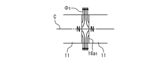
- the magnetic flux lines ⁇ 1 is from the end of the permanent magnet 11 (N pole), it generally exits the perpendicular outward direction to large yoke member 16a 1 and through to the center axis C of the saturation magnetic flux density it can. That is, to derive the magnetic field through the yoke member 16a 1 to the outside, it is possible to increase the magnetic flux density in the direction perpendicular to the center axis C at the position of the coil portion 3. As a result, the thrust of the linear actuator can be increased. For example, other than the insertion of the yoke members 16a 1 under the experimental conditions were the same, an increase of + 8.9% of thrust has been confirmed.
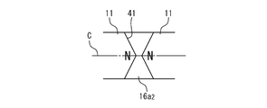
- FIG. 4A and 4B are schematic cross-sectional views showing other examples of the specific configuration of the intermediate member according to the first embodiment of the present invention.
- the intermediate member 16 illustrated in FIG. 4A is a yoke member 16a 2 formed of a soft magnetic material (high magnetic permeability material).
- the saturation magnetic flux density of the soft magnetic material is larger than the saturation magnetic flux density of the permanent magnet 11, more preferably larger than twice the saturation magnetic flux density of the permanent magnet 11.
- Soft magnetic materials are exemplified by pure iron (such as electromagnetic soft iron), permalloy, and silicon steel.
- the yoke member 16a 2 the center axis C of the thickness is thicker with increasing distance from the central axis C.
- the conical recesses 41 centered on the central axis C are provided on two surfaces in contact with the permanent magnet 11.
- magnetic flux lines ⁇ 2 is from the end of the permanent magnet 11 (N pole), it generally exits the perpendicular outward direction to large yoke member 16a 2 passes through the central axis C of the saturation magnetic flux density it can.
- the center axis C direction of the thickness is thicker with increasing distance from the central axis C, also can prevent the concentration of magnetic flux in the yoke member 16a 2 peripheral portion, it is possible to prevent the occurrence of magnetic saturation. That is, to derive the magnetic field through the yoke member 16a 2 to the outside, while preventing magnetic saturation due to the concentration of magnetic flux, it is possible to increase the vertical direction of the magnetic flux to the central axis C at the position of the coil portion 3. As a result, the thrust of the linear actuator can be further increased.
- FIGS. 5A and 5B are schematic cross-sectional views showing still another example of the specific configuration of the intermediate member according to the first embodiment of the present invention.
- the intermediate members 16 shown in FIGS. 5A and 5B are yoke members 16a 3 and 16a 4 formed of a soft magnetic material (high magnetic permeability material), respectively.
- These yoke members 16a 3 and 16a 4 are basically the same as the yoke member 16a 2 (thickness in the direction of the central axis C increases with increasing distance from the central axis C). However, it is different from the recess 41 of the yoke member 16a 2 the shape of the recess 42, 43 around the central axis C.
- the yoke member 16a 3 of Figure 5A has a shape having a recess 42 formed in a curved surface (shape like a concave lens).
- the yoke member 16a 4 in Figure 5B has a shape having a recess 43 formed in the stepped multiple stages. Any shape can obtain the same effect as the shape of FIG. 4A and FIG. 4B.
- 2A and 2B are schematic perspective views showing the configuration of the linear actuator according to the second embodiment of the present invention.
- this figure is the same as that of the first embodiment, and the description thereof is omitted.
- FIG. 6A to 6D are schematic cross-sectional views showing an example of a specific configuration of the intermediate member according to the second embodiment of the present invention.
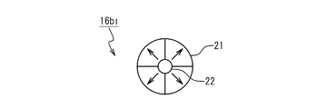
- the intermediate member 16 shown in FIG. 6A is a permanent magnet member 16b 1 formed of a hard magnetic material (high coercive force material), and is, for example, a ferrite magnet or a rare earth magnet.
- FIG. 6B is a plan view of the magnet member 16b 1 disposed between two N poles as viewed from the direction of the central axis C.
- the magnet member 16b 1 has an annular shape having a cylindrical opening 22 at the center.
- the magnet member 16b 1 is formed into an annular shape by combining a plurality of fan-shaped magnets 21. By dividing, it becomes easy to manufacture an annulus having a magnetization direction radially. In the case of FIG. 6B, four fan-shaped magnets 21 are combined.
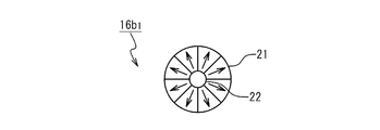
- the present invention is not limited to this number. For example, more fan-shaped magnet members may be combined (example: six in FIG. 6D).
- FIG. 6C is a plan view of the magnet member 16b 1 disposed between the two S poles as viewed from the direction of the central axis C. The magnet member 16b 1 even other magnetization direction opposite to, the same as in the case shown in Figure 6B.
- the magnetic flux state in FIG. 6A is the same as in FIG. 3B. Therefore, a linear actuator using the magnet member 16b 1 in Figure 6A, it is possible to obtain the same effect as the case of FIG. 3A. That is, the magnetic field can be led out through the magnet member 16b 1 and the magnetic flux density in the direction perpendicular to the central axis C at the position of the coil portion 3 can be increased. As a result, the thrust of the linear actuator can be increased.
- an increase magnet volume not only the magnetic flux of the permanent magnet 11, the magnetic flux of the magnet member 16b 1 itself is added.
- the saturation magnetic flux density of the magnet member 16b 1 is generally more limited than that of the soft magnetic material 16a 1 of FIGS. 3A and 3B, and the superiority or inferiority of the performance compared with the case of FIGS. Cannot be determined.
- FIG. 7A to 7C are schematic cross-sectional views showing other examples of the specific configuration of the intermediate member according to the second embodiment of the present invention.
- the intermediate member 16 shown in FIG. 7A is a permanent magnet member 16b 2 formed of a hard magnetic material (high coercive force material), and is, for example, a ferrite magnet or a rare earth magnet.
- the magnet member 16b 2 has a thickness in the direction of the central axis C that increases with distance from the central axis C.
- the conical recesses 51 centered on the central axis C are provided on the two surfaces in contact with the permanent magnet 11.
- two planes viewed magnet member 16b 2 from the central axis C direction is arranged in N machining gap and two S interpolar view is omitted because it is similar to FIG. 6B ⁇ Figure 6D.
- FIG. 7A The state of the magnetic flux lines in FIG. 7A is the same as in FIG. 4B. Therefore, a linear actuator using the magnet member 16b 2 in FIG. 7A can obtain the same effect as the case of FIG. 4B.
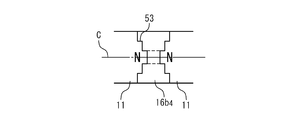
- the intermediate member 16 shown in FIGS. 7B and 7C are magnet members 16b 3 and 16b 4 formed of a hard magnetic material (high holding power material), respectively.
- These magnet members 16b 3 and 16b 4 are basically the same as the magnet member 16b 2 (thickness in the direction of the central axis C increases with increasing distance from the central axis C).
- the shape of the recess 52, 53 around the central axis C it is different from the recess 51 of the magnet member 16b 2 the shape of the recess 52, 53 around the central axis C. That is, the magnet member 16b 3 in FIG. 7B has a shape having a concave portion 52 formed in a curved surface (a shape like a concave lens).
- the magnet member 16b 4 in FIG. 7C has a shape having a recess 53 formed by a plurality of steps. In any shape, the same effect as the shape of FIG. 7A can be obtained.
- FIG. 8 is a schematic cross-sectional view showing the relationship in size between the intermediate member and the permanent magnet according to the second embodiment of the present invention.
- the thickness X of the permanent magnet 11 in the central axis C direction is preferably larger than the thickness Y of the magnet member 16 in the central axis C direction (X> Y). More preferably, X>Y> X / 10. With such a relationship, the magnetic flux density in the direction perpendicular to the central axis C at the position of the coil portion 3 can be further increased.
- the volume of the permanent magnet 11 that mainly generates magnetic flux can be kept large, the magnetic flux component penetrating the coil 3 vertically can be increased, and the thrust of the linear actuator can be further increased.
- the thrust of the linear actuator can be further increased.
- FIG. 9 is a schematic cross-sectional view showing still another example of the specific configuration of the intermediate member according to the second embodiment of the present invention.
- the intermediate member 16 shown in FIG. 9 is a synthetic member 16 c having a shape in which a circular ring formed by combining fan-shaped magnets 21 is further surrounded by a circular ring of the soft magnetic member 23. That is, the intermediate member 16 has a configuration in which the intermediate member of the first embodiment and the intermediate member of the second embodiment are combined.
- the reason why the soft magnetic member 23 is used on the outside is that the portion where the magnetic flux is more likely to concentrate is outside. That is, if the magnet is arranged outside, the magnetic flux of the magnet itself is added, but there is a possibility that the magnetic flux is concentrated in the outer region and magnetic saturation occurs.
- the effects of the present embodiment and the first embodiment can be obtained. Further, the shape thereof may be modified as shown in FIGS. 4A and 4B, FIGS. 5A and 5B, and FIGS. 7A to 7C. In this case, the effects of the present embodiment and the first embodiment are also possible. Can be obtained.
- FIG. 10 is a schematic perspective view showing the configuration of the linear actuator according to the third embodiment of the present invention.
- the linear actuator 1a of the third embodiment is the first embodiment and the second embodiment (FIGS. 2A and 2B) in that the fixed actuator 17 is provided and the outer cylinder 14 is not provided. Different from 2B).
- the fixed shaft member 17 is provided in the shaft portion 2 and penetrates the plurality of permanent magnets 11 and the plurality of intermediate members 16 in the central axis C direction.
- the fixed shaft member 17 is formed of a non-magnetic material so that the magnetic flux does not easily pass through a path other than the coil 3.
- the fixed shaft member 17 has a substantially cylindrical shape (cylindrical bar shape), and the central axis is the central axis C.
- male screws 27 are provided at both ends of the fixed shaft member 17.
- the plurality of permanent magnets 11 and the plurality of intermediate members 16 can be easily fixed by tightening the male screw 27 with the female screw member 9 from both ends of the fixed shaft member 17.
- FIG. 11 is a schematic plan view showing configurations of the permanent magnet 11 and the intermediate member according to the third embodiment of the present invention.
- the permanent magnet 11 and the intermediate member 16 have an annular shape having an opening 25 having the same diameter as that of the fixed shaft member 17 at the center.
- the intermediate member 16 may be as shown in FIGS. 3A and 3B to 9 described in the first and second embodiments, and in that case, the same effect as the first and second embodiments can be obtained. Can be obtained.
- FIG. 12 is a schematic perspective view showing a modification of the configuration of the linear actuator according to the first to third embodiments of the present invention.
- the structure of one cycle of the permanent magnet 11 / intermediate member 16 moves on the shaft member 37.
- the intermediate member 16 similar to that in the first to third embodiments can be used. Thereby, the same effects as those of the above embodiments can be obtained.
- the shape of the cross section perpendicular to the central axis C of the shaft portion 2 and the coil portion 3 is circular.
- the present invention is not limited to this, and the cross-sectional shape perpendicular to the central axis C may be a polygon (not shown). For example, a triangle, a quadrangle, a hexagon, an octagon, or a dodecagon.
- the cross-sectional shape is polygonal, when the mover, for example, the coil part 2 moves, it can be made difficult to rotate in the circumferential direction, and it can be used for applications where relative rotational motion is not preferred. .
- the magnetic field is guided by the action of an intermediate member such as a yoke member or a magnet member.
- the magnetic flux density in the vertical direction can be increased, and the operating thrust of the linear actuator can be increased.
Abstract
A linear actuator is provided with a coil section and a shaft section. The coil section has a plurality of coils wherein alternating currents in phases different from each other flow. The shaft section passes inside the coils. The shaft section is provided with a plurality of permanent magnets and a plurality of intermediate members. The permanent magnets face each other with opposite magnetization directions with respect to the direction of a center axis (C) and are arranged along the center axis (C). The intermediate members are arranged between the permanent magnets, respectively. In order to lead out each magnetic flux of the permanent magnets to the outside, the intermediate members are composed of a soft magnetic material having a relatively high saturation magnetic flux density or a permanent magnet magnetized in the direction perpendicular to the axis.
Description
本発明は、リニアアクチュエータに関し、特にリニア同期モータの原理を用いたリニアアクチュエータに関する。
The present invention relates to a linear actuator, and more particularly to a linear actuator using the principle of a linear synchronous motor.
磁石の磁極同士の吸引力及び反発力を利用したリニアモータであるリニア同期モータが知られている。そのリニア同期モータの一種として、シャフトモーターがある。例えば、株式会社ジイエムシーヒルストンのホームページにシャフトモーターが開示されている(http://www.ghc.co.jp/product/shaft.html)。
A linear synchronous motor, which is a linear motor that uses the attractive force and repulsive force between magnetic poles of a magnet, is known. One type of linear synchronous motor is a shaft motor. For example, a shaft motor is disclosed on the homepage of DMC Hillstone Co., Ltd. (http://www.ghc.co.jp/product/shaft.html).
図1は、そのシャフトモーターの構成を示す概略図である。このシャフトモーター101は、シャフト部102及びコイル部103を具備している。シャフト部102は、複数の永久磁石111及び外筒114を備えている。複数の永久磁石111は、磁気方向が中心軸Cの方向に対して正逆対向し、中心軸Cに沿って配置されている。すなわち、中心軸Cに沿って、N極同士、S極同士が接合されている。そのため、接合部112から強い磁力線が発生している。外筒114は、複数の永久磁石111を一体的に格納する円筒である。一方、コイル部103は、コイル118を備えている。コイル118は、中心軸が共通であり、互いに位相の異なる交流電流が流れる複数のコイル118(例示:U相用、V相用、W相用)を有している。シャフト部102は、それら複数のコイル118の内側を貫通している。このシャフト部102を取り囲む複数のコイル118に電流が流れると磁界が発生し、フレミングの左手の法則により推力が発生する。この推力によって、コイル部103が中心軸Cに沿って直動運動する。
FIG. 1 is a schematic diagram showing the configuration of the shaft motor. The shaft motor 101 includes a shaft portion 102 and a coil portion 103. The shaft portion 102 includes a plurality of permanent magnets 111 and an outer cylinder 114. The plurality of permanent magnets 111 are arranged along the central axis C such that the magnetic direction is opposite to the direction of the central axis C. That is, the north poles and the south poles are joined along the central axis C. Therefore, strong magnetic field lines are generated from the joint 112. The outer cylinder 114 is a cylinder that integrally stores a plurality of permanent magnets 111. On the other hand, the coil unit 103 includes a coil 118. The coil 118 has a common central axis and includes a plurality of coils 118 (for example, for U phase, for V phase, and for W phase) through which alternating currents having different phases flow. The shaft portion 102 passes through the inside of the plurality of coils 118. When a current flows through the plurality of coils 118 surrounding the shaft portion 102, a magnetic field is generated, and thrust is generated according to Fleming's left-hand rule. The coil portion 103 moves linearly along the central axis C by this thrust.
このシャフトモーター101は、コイル118とシャフト部102との間に吸着力が働かない、磁石111の磁束を磁石111の全周で無駄無く有効活用できて高推力である、などの特徴がある。そして、このシャフトモーターは、その機能や特徴を利用して、ボールネジを代替する機械要素として、あるいは、アクチュエータの一つとしてのリニアアクチュエータとして使用することが可能である。
This shaft motor 101 is characterized in that no attracting force acts between the coil 118 and the shaft portion 102, and that the magnetic flux of the magnet 111 can be effectively utilized all around the magnet 111 without waste and has high thrust. The shaft motor can be used as a mechanical element that replaces the ball screw or as a linear actuator as one of the actuators by utilizing its function and characteristics.
関連する技術として、特開2003-70226号公報にリニア同期モータが開示されている。このリニア同期モータは、コイルを有する一次側可動子と、複数の永久磁石を直線に沿って配置した二次側固定子とを備え、コイルに通電することにより可動子を二次側固定子に沿って直線的に移動させる。このリニア同期モータは、複数の永久磁石を隣接して配置すると共に、隣接する永久磁石の磁化方向を可動子の移動方向及び直角方向に90度ずつ異ならせている。
As a related technique, a linear synchronous motor is disclosed in Japanese Patent Application Laid-Open No. 2003-70226. This linear synchronous motor includes a primary side mover having a coil and a secondary side stator in which a plurality of permanent magnets are arranged along a straight line, and energizing the coil makes the mover a secondary side stator. Move along a straight line. In this linear synchronous motor, a plurality of permanent magnets are arranged adjacent to each other, and the magnetization directions of the adjacent permanent magnets are varied by 90 degrees in the moving direction and the perpendicular direction of the mover.
また、特開2007-6545号公報に周期磁界発生装置およびそれを用いたリニアモータ、回転型モータ、揺動モータが開示されている。この周期磁界発生装置は、発生磁界の方向に磁化された主磁極永久磁石と主磁極永久磁石の磁極の向きと異なるように磁化された副磁極永久磁石から構成されるハルバッハ配列構造の界磁極を備えている。この周期磁界発生装置は、主磁極永久磁石の磁界発生側の一部を軟磁性材料で置き換えている。
Also, Japanese Patent Application Laid-Open No. 2007-6545 discloses a periodic magnetic field generator and a linear motor, a rotary motor, and a swing motor using the same. This periodic magnetic field generator has a Halbach array field pole composed of a main magnetic pole permanent magnet magnetized in the direction of the generated magnetic field and a sub magnetic pole permanent magnet magnetized differently from the magnetic pole direction of the main magnetic pole permanent magnet. I have. In this periodic magnetic field generator, a part of the main pole permanent magnet on the magnetic field generation side is replaced with a soft magnetic material.
発明者は、以下の事実を新たに発見した。上記のシャフトモーター101には以下のような問題があると考えられる。第1の問題は、磁石111を対向させて直接接触させて配置するので、対向する磁石111同士が互いに磁界を弱め合っているということである。すなわち、接触面付近の磁石の動作点が、隣接する磁石により発生する磁界の影響により変化し、磁石の性能を十分発揮できない状態にある。また、第2の問題として、磁石111の接触面の磁束は、接触面の両側の磁石111内を通過しなければならず、その磁束の大きさはその磁石111の飽和磁束密度により制限されてしまう。そのため、個々の磁石111の磁力の強さを十分に生かすことができていないと考えられる。第3の問題は、磁石111を対向させて配置するので、隣り合う磁石111が互いに反発し合い、組み立てが難しいということである。特に、推力の向上には磁石111の磁力を高めることが必要であるが、そうなると益々組み立てが困難になることが予想される。第4の問題は、磁石111を固定するために、磁石111を収めるチューブ状の外筒114が必須であることである。そのため、この外筒114の存在により、コイル118と磁石111との間のギャップが増加し、推力が低下する。
The inventor has newly discovered the following facts. The shaft motor 101 is considered to have the following problems. The first problem is that the magnets 111 facing each other are arranged in direct contact with each other, so that the opposing magnets 111 weaken each other's magnetic field. That is, the operating point of the magnet in the vicinity of the contact surface changes due to the influence of the magnetic field generated by the adjacent magnet, and the performance of the magnet is not sufficiently exhibited. As a second problem, the magnetic flux on the contact surface of the magnet 111 must pass through the magnets 111 on both sides of the contact surface, and the magnitude of the magnetic flux is limited by the saturation magnetic flux density of the magnet 111. End up. Therefore, it is considered that the strength of the magnetic force of each magnet 111 cannot be fully utilized. The third problem is that since the magnets 111 are arranged to face each other, the adjacent magnets 111 repel each other and are difficult to assemble. In particular, it is necessary to increase the magnetic force of the magnet 111 in order to improve the thrust, but it is expected that assembly will become increasingly difficult. The fourth problem is that in order to fix the magnet 111, a tube-shaped outer cylinder 114 that houses the magnet 111 is essential. Therefore, due to the presence of the outer cylinder 114, the gap between the coil 118 and the magnet 111 increases, and the thrust decreases.
上記シャフトモーターをリニアアクチュエータとして用いる場合において、その磁石の磁力の強さを十分に活用することができる技術が望まれる。その組み立てを容易にすることが可能な技術が望まれる。コイルと磁石との間のギャップを低減し推力を向上させることが可能な技術が求められる。
When using the shaft motor as a linear actuator, a technique that can fully utilize the magnetic force of the magnet is desired. A technique capable of facilitating the assembly is desired. A technique capable of reducing the gap between the coil and the magnet and improving the thrust is required.
本発明の目的は、磁石の磁力の強さを十分に活用することができるリニアアクチュエータを提供することにある。また、本発明の他の目的は、組み立てを容易にすることが可能なリニアアクチュエータを提供することにある。また、本発明の更に他の目的は、コイルと磁石との間のギャップを低減し推力を向上させることが可能なリニアアクチュエータを提供することにある。
An object of the present invention is to provide a linear actuator that can fully utilize the magnetic force of a magnet. Another object of the present invention is to provide a linear actuator that can be easily assembled. Still another object of the present invention is to provide a linear actuator capable of reducing the gap between the coil and the magnet and improving the thrust.
本発明のリニアアクチュエータは、コイル部と、シャフト部とを具備する。コイル部は、互いに位相の異なる交流電流が流れる複数のコイルを有する。シャフト部は、複数のコイルの内側を通る。シャフト部は、複数の永久磁石と、複数の中間部材とを備える。複数の永久磁石は、磁化方向が中心軸の方向に対して正逆対向し、中心軸に沿って配置されている。複数の中間部材は、複数の永久磁石の各々の間に配置されている。複数の中間部材の各々の飽和磁束密度は、複数の永久磁石の各々の飽和磁束密度よりも大きい。
The linear actuator of the present invention includes a coil portion and a shaft portion. The coil unit includes a plurality of coils through which alternating currents having different phases flow. The shaft portion passes through the inside of the plurality of coils. The shaft portion includes a plurality of permanent magnets and a plurality of intermediate members. The plurality of permanent magnets are arranged along the central axis such that the magnetization direction is opposite to the direction of the central axis. The plurality of intermediate members are disposed between each of the plurality of permanent magnets. The saturation magnetic flux density of each of the plurality of intermediate members is greater than the saturation magnetic flux density of each of the plurality of permanent magnets.
本発明では、対向する永久磁石同士の間に中間部材として、永久磁石よりも飽和磁束密度が高い、軟磁性材料が挿入されている。この中間部材の飽和磁束密度が永久磁石の飽和磁束密度よりも大きいという性質により、対向する永久磁石同士の磁束は、中間部材内において、永久磁石のみで構成された場合よりも高い磁束密度で、いずれも中間部材を通って中心軸に略垂直な方向へ抜ける、又は同方向から入ることができる。これにより、そのコイル部の位置での磁束密度を増加させることができる。すなわち、対向する磁石同士が互いに磁界を弱め合わないので、個々の磁石の磁力の強さを十分に生かすことができる。それにより、リニアアクチュエータの推力を増加させることができる。また、この中間部材を介在させることで、隣合う磁石が互いに反発し合う力を弱めることができる。それにより、シャフト部の組み立てを容易にすることができる。すなわち、リニアアクチュエータの製造を容易にすることが可能となる。
In the present invention, a soft magnetic material having a saturation magnetic flux density higher than that of the permanent magnet is inserted as an intermediate member between the opposing permanent magnets. Due to the property that the saturation magnetic flux density of the intermediate member is larger than the saturation magnetic flux density of the permanent magnet, the magnetic flux between the opposing permanent magnets is higher than that in the case where the intermediate member is composed of only the permanent magnet, Both can pass through the intermediate member in a direction substantially perpendicular to the central axis, or can enter from the same direction. Thereby, the magnetic flux density in the position of the coil part can be increased. That is, since the opposing magnets do not weaken each other's magnetic field, the strength of the magnetic force of each magnet can be fully utilized. Thereby, the thrust of the linear actuator can be increased. Further, by interposing this intermediate member, the force with which the adjacent magnets repel each other can be weakened. Thereby, the assembly of a shaft part can be made easy. That is, it becomes possible to easily manufacture the linear actuator.
本発明では、中間部材として軟磁性材料を用いているので、対向する永久磁石同士の間での磁束の集中による磁気飽和の防止を安価に行うことができる。そのため、リニアアクチュエータの推力の向上を低コストで行うことができる。
In the present invention, since a soft magnetic material is used as the intermediate member, magnetic saturation due to concentration of magnetic flux between the opposing permanent magnets can be prevented at a low cost. Therefore, the thrust of the linear actuator can be improved at a low cost.
本発明のリニアアクチュエータは、複数の中間部材の各々が、磁石材料で形成された中間磁石部材を含む。その場合、中間磁石部材は、磁化方向が中心軸の方向に対して垂直外向き、及び、垂直内向きに、中心軸に沿って交互に配置されていることが好ましい。
本発明では、中間部材により磁束が中心軸に略垂直な方向へと導かれるため,対向する永久磁石同士の間で磁界を弱めあうことなく,さらに中間部在の磁力も加えることで,コイル部での磁束密度を高めることができる。その結果、リニアアクチュエータの推力を増加させることができる。 In the linear actuator of the present invention, each of the plurality of intermediate members includes an intermediate magnet member formed of a magnet material. In that case, it is preferable that the intermediate magnet members are alternately arranged along the central axis so that the magnetization direction is perpendicular outward and perpendicular inward to the direction of the central axis.
In the present invention, since the magnetic flux is guided in the direction substantially perpendicular to the central axis by the intermediate member, the magnetic force of the intermediate portion is further applied without weakening the magnetic field between the opposing permanent magnets. Can increase the magnetic flux density. As a result, the thrust of the linear actuator can be increased.
なお、上記のリニアアクチュエータにおいて、複数の中間部材の各々における中心軸方向の厚みは、複数の永久磁石の各々における中心軸方向の厚みよりも薄いことが好ましい。
本発明では、中間部材の厚みを、永久磁石の厚みよりも薄くすることで、リニアアクチュエータの推力を増加させることができる。 In the linear actuator, the thickness in the central axis direction of each of the plurality of intermediate members is preferably thinner than the thickness in the central axis direction of each of the plurality of permanent magnets.
In the present invention, the thrust of the linear actuator can be increased by making the thickness of the intermediate member thinner than the thickness of the permanent magnet.
上記のリニアアクチュエータにおいて、複数の中間部材の各々は、中間磁石部材を囲み、軟磁性材料で形成されたヨーク部材を更に含むことが好ましい。
本発明では、中間部材として軟磁性材料と磁石材料とを組み合わせて用いている。そのため、対向する永久磁石同士の間での磁束の集中による磁気飽和を防ぎつつ、磁石の体積を増加させて磁束密度を高めつつ、一部を難磁性材料にしてコストを低く抑えることができる。それにより、コイル部での磁束密度を、低いコストでより高めることができる。その結果、コストを抑えつつ、リニアアクチュエータの推力を増加させることができる。 In the above linear actuator, each of the plurality of intermediate members preferably further includes a yoke member that surrounds the intermediate magnet member and is formed of a soft magnetic material.
In the present invention, a soft magnetic material and a magnet material are used in combination as the intermediate member. Therefore, while preventing magnetic saturation due to the concentration of the magnetic flux between the opposing permanent magnets, the volume of the magnet can be increased to increase the magnetic flux density, and part of the material can be made of a hardly magnetic material to keep the cost low. Thereby, the magnetic flux density in a coil part can be raised more at low cost. As a result, the thrust of the linear actuator can be increased while suppressing the cost.
上記のリニアアクチュエータにおいて、複数の中間部材の各々は、中心軸方向の厚みが、前記中心軸から離れるにつれて厚くなることが好ましい。
本発明では、磁束の混み具合が相対的に小さい中心軸付近の中間部材の厚みを薄くし、磁束の集中度合いが相対的に大きい表面付近の厚みを厚くしている。これにより、中間部材内での磁束の集中による磁気飽和の発生を低減することができる。その結果、コイル部での磁束密度をより高めることができる。その結果、リニアアクチュエータの推力を増加させることができる。 In the linear actuator, it is preferable that each of the plurality of intermediate members has a thickness in the central axis direction that increases with distance from the central axis.
In the present invention, the thickness of the intermediate member near the central axis where the degree of magnetic flux crowding is relatively small is reduced, and the thickness near the surface where the concentration of magnetic flux is relatively large is increased. Thereby, generation | occurrence | production of the magnetic saturation by the concentration of the magnetic flux in an intermediate member can be reduced. As a result, the magnetic flux density in the coil portion can be further increased. As a result, the thrust of the linear actuator can be increased.
上記のリニアアクチュエータにおいて、シャフト部は、複数の永久磁石と複数の中間部材とを貫通して固定する固定軸部材を更に備えることが好ましい。
本発明では、永久磁石と中間部材とを貫通して固定する固定軸部材を有しているので、永久磁石を固定するためのチューブ状の外筒が不要である。そのため、コイルと磁石との間のギャップをより小さくすることができる。それにより、コイル部での磁束密度をより高めることができ、リニアアクチュエータの推力を増加させることができる。 In the above linear actuator, it is preferable that the shaft portion further includes a fixed shaft member that penetrates and fixes the plurality of permanent magnets and the plurality of intermediate members.
In this invention, since it has the fixed shaft member which penetrates and fixes a permanent magnet and an intermediate member, the tube-shaped outer cylinder for fixing a permanent magnet is unnecessary. Therefore, the gap between the coil and the magnet can be further reduced. Thereby, the magnetic flux density in a coil part can be raised more and the thrust of a linear actuator can be increased.
上記のリニアアクチュエータにおいて、シャフト部及びコイル部は、中心軸に垂直な断面の形状が多角形であることが好ましい。
本発明では、断面の形状が多角形であるため、コイル部が周方向に回転し難い。そのため、コイル部を中心軸方向に円滑に動作させることが出来る。 In the above linear actuator, the shaft portion and the coil portion preferably have a polygonal cross-sectional shape perpendicular to the central axis.
In the present invention, since the cross-sectional shape is a polygon, the coil portion is difficult to rotate in the circumferential direction. Therefore, the coil portion can be smoothly operated in the central axis direction.
本発明により、リニアアクチュエータにおいて、磁石の磁力の強さを十分に活用することができる。また、リニアアクチュエータにおいて、組み立てを容易にすることが可能となる。また、リニアアクチュエータにおいて、コイルと磁石との間のギャップを低減し推力を向上させることが可能となる。
According to the present invention, the magnetic force of the magnet can be fully utilized in the linear actuator. In addition, the linear actuator can be easily assembled. Further, in the linear actuator, the gap between the coil and the magnet can be reduced and the thrust can be improved.
本発明の前記及びその他の目的、長所及び特徴は、添付の図面を考慮して次の実施の形態の記載によって、より詳細に分かるであろう。
図1は、株式会社ジイエムシーヒルストンのシャフトモーターの構成を示す概略図である。
図2Aは、本発明の第1及び第2の実施の形態に係るリニアアクチュエータの構成を示す概略斜視図である。
図2Bは、本発明の第1及び第2の実施の形態に係るリニアアクチュエータの構成を示す概略斜視図である。
図3Aは、本発明の第1の実施の形態に係る中間部材の具体的構成の一例を示す概略断面図である。
図3Bは、本発明の第1の実施の形態に係る中間部材の具体的構成の一例を示す概略断面図である。
図4Aは、本発明の第1の実施の形態に係る中間部材の具体的構成の他の例を示す概略断面図である。
図4Bは、本発明の第1の実施の形態に係る中間部材の具体的構成の他の例を示す概略断面図である。
図5Aは、本発明の第1の実施の形態に係る中間部材の具体的構成の更に他の例を示す概略断面図である。
図5Bは、本発明の第1の実施の形態に係る中間部材の具体的構成の更に他の例を示す概略断面図である。
図6Aは、本発明の第2の実施の形態に係る中間部材の具体的構成の一例を示す概略断面図である。
図6Bは、本発明の第2の実施の形態に係る中間部材の具体的構成の一例を示す概略断面図である。
図6Cは、本発明の第2の実施の形態に係る中間部材の具体的構成の一例を示す概略断面図である。
図6Dは、本発明の第2の実施の形態に係る中間部材の具体的構成の一例を示す概略断面図である。
図7Aは、本発明の第2の実施の形態に係る中間部材の具体的構成の他の例を示す概略断面図である。
図7Bは、本発明の第2の実施の形態に係る中間部材の具体的構成の他の例を示す概略断面図である。
図7Cは、本発明の第2の実施の形態に係る中間部材の具体的構成の他の例を示す概略断面図である。
図8は、本発明の第2の実施の形態に係る中間部材と永久磁石との大きさの関係を示す概略断面図である。
図9は、本発明の第2の実施の形態に係る中間部材の具体的構成の更に他の例を示す概略断面図である。
図10は、本発明の第3の実施の形態に係るリニアアクチュエータの構成を示す概略斜視図である。
図11は、本発明の第3の実施の形態に係る永久磁石及び中間部材の構成を示す概略平面図である。
図12は、本発明の第1~第3の実施の形態に係るリニアアクチュエータの構成の変形例を示す概略斜視図である。
The above and other objects, advantages, and features of the present invention will be understood in more detail by the following description of embodiments with reference to the accompanying drawings.
FIG. 1 is a schematic view showing the configuration of a shaft motor of GM Hillstone Co., Ltd. FIG. 2A is a schematic perspective view showing the configuration of the linear actuator according to the first and second embodiments of the present invention. FIG. 2B is a schematic perspective view showing the configuration of the linear actuator according to the first and second embodiments of the present invention. FIG. 3A is a schematic cross-sectional view showing an example of a specific configuration of the intermediate member according to the first embodiment of the present invention. FIG. 3B is a schematic cross-sectional view showing an example of a specific configuration of the intermediate member according to the first embodiment of the present invention. FIG. 4A is a schematic cross-sectional view showing another example of the specific configuration of the intermediate member according to the first embodiment of the present invention. FIG. 4B is a schematic cross-sectional view showing another example of the specific configuration of the intermediate member according to the first embodiment of the present invention. FIG. 5A is a schematic cross-sectional view showing still another example of the specific configuration of the intermediate member according to the first embodiment of the present invention. FIG. 5B is a schematic cross-sectional view showing still another example of the specific configuration of the intermediate member according to the first embodiment of the present invention. FIG. 6A is a schematic cross-sectional view showing an example of a specific configuration of the intermediate member according to the second embodiment of the present invention. FIG. 6B is a schematic cross-sectional view showing an example of a specific configuration of the intermediate member according to the second embodiment of the present invention. FIG. 6C is a schematic cross-sectional view showing an example of a specific configuration of the intermediate member according to the second embodiment of the present invention. FIG. 6D is a schematic cross-sectional view showing an example of a specific configuration of the intermediate member according to the second embodiment of the present invention. FIG. 7A is a schematic cross-sectional view showing another example of the specific configuration of the intermediate member according to the second embodiment of the present invention. FIG. 7B is a schematic cross-sectional view showing another example of the specific configuration of the intermediate member according to the second embodiment of the present invention. FIG. 7C is a schematic cross-sectional view showing another example of the specific configuration of the intermediate member according to the second exemplary embodiment of the present invention. FIG. 8 is a schematic cross-sectional view showing the relationship in size between the intermediate member and the permanent magnet according to the second embodiment of the present invention. FIG. 9 is a schematic cross-sectional view showing still another example of the specific configuration of the intermediate member according to the second embodiment of the present invention. FIG. 10 is a schematic perspective view showing the configuration of the linear actuator according to the third embodiment of the present invention. FIG. 11 is a schematic plan view showing configurations of a permanent magnet and an intermediate member according to the third embodiment of the present invention. FIG. 12 is a schematic perspective view showing a modification of the configuration of the linear actuator according to the first to third embodiments of the present invention.
以下、本発明のリニアアクチュエータの実施の形態に関して、添付図面を参照して説明する。
Hereinafter, embodiments of the linear actuator of the present invention will be described with reference to the accompanying drawings.
(第1の実施の形態)
まず、本発明の第1の実施の形態に係るリニアアクチュエータの構成について説明する。
図2A及び図2Bは、本発明の第1の実施の形態に係るリニアアクチュエータの構成を示す概略斜視図である。図中の矢印、「○に点」印(手前側向き)、「丸にバツ」印(奥側向き)は、いずれも磁化方向や磁力線の向きを示している(以下、各図面において同じ)。図2Aに示すように、このシャフトモーター1は、シャフト部2及びコイル部3を具備している。シャフト部2の形状は棒状であり、例えば円柱状である。コイル部3の形状は筒状であり、例えば円筒状である。シャフト部2は、コイル部3の内側を通るように配置されている。シャフト部2及びコイル部3の中心軸は概ね重なっている(以下、中心軸C)。そして、コイル部3に電流を流すことにより、コイル部3は、シャフト部2上をその中心軸C方向に相対的に移動する。 (First embodiment)
First, the configuration of the linear actuator according to the first embodiment of the present invention will be described.
2A and 2B are schematic perspective views showing the configuration of the linear actuator according to the first embodiment of the present invention. The arrows in the figure, “Dotted to ○” (facing the near side), and “Circularly crossing” (facing the back) all indicate the direction of magnetization and the direction of the lines of magnetic force (hereinafter the same in each drawing). . As shown in FIG. 2A, the shaft motor 1 includes ashaft portion 2 and a coil portion 3. The shape of the shaft portion 2 is a rod shape, for example, a columnar shape. The shape of the coil part 3 is cylindrical, for example, cylindrical. The shaft portion 2 is disposed so as to pass inside the coil portion 3. The central axes of the shaft portion 2 and the coil portion 3 are substantially overlapped (hereinafter, the central axis C). And by passing an electric current through the coil part 3, the coil part 3 moves relatively on the shaft part 2 in the direction of the central axis C.
まず、本発明の第1の実施の形態に係るリニアアクチュエータの構成について説明する。
図2A及び図2Bは、本発明の第1の実施の形態に係るリニアアクチュエータの構成を示す概略斜視図である。図中の矢印、「○に点」印(手前側向き)、「丸にバツ」印(奥側向き)は、いずれも磁化方向や磁力線の向きを示している(以下、各図面において同じ)。図2Aに示すように、このシャフトモーター1は、シャフト部2及びコイル部3を具備している。シャフト部2の形状は棒状であり、例えば円柱状である。コイル部3の形状は筒状であり、例えば円筒状である。シャフト部2は、コイル部3の内側を通るように配置されている。シャフト部2及びコイル部3の中心軸は概ね重なっている(以下、中心軸C)。そして、コイル部3に電流を流すことにより、コイル部3は、シャフト部2上をその中心軸C方向に相対的に移動する。 (First embodiment)
First, the configuration of the linear actuator according to the first embodiment of the present invention will be described.
2A and 2B are schematic perspective views showing the configuration of the linear actuator according to the first embodiment of the present invention. The arrows in the figure, “Dotted to ○” (facing the near side), and “Circularly crossing” (facing the back) all indicate the direction of magnetization and the direction of the lines of magnetic force (hereinafter the same in each drawing). . As shown in FIG. 2A, the shaft motor 1 includes a
シャフト部2は、複数の永久磁石11と、複数の中間部材16と、外筒14とを備えている。
複数の永久磁石11は、磁化方向が中心軸Cの方向に対して正逆対向し、中心軸Cに沿って配置されている。すなわち、中心軸Cに沿って、N極同士、S極同士が向かい合って配置されている。永久磁石11は、例えば、略円柱形状を有している。その中心軸は、中心軸Cである。永久磁石11は、従来知られた各種の永久磁石を用いることができ、例えば、フェライト磁石、希土類磁石である。 Theshaft portion 2 includes a plurality of permanent magnets 11, a plurality of intermediate members 16, and an outer cylinder 14.
The plurality ofpermanent magnets 11 are arranged along the central axis C such that the magnetization direction is opposite to the direction of the central axis C. That is, along the central axis C, the N poles and the S poles are arranged facing each other. The permanent magnet 11 has, for example, a substantially cylindrical shape. The central axis is the central axis C. As the permanent magnet 11, various kinds of conventionally known permanent magnets can be used, for example, a ferrite magnet or a rare earth magnet.
複数の永久磁石11は、磁化方向が中心軸Cの方向に対して正逆対向し、中心軸Cに沿って配置されている。すなわち、中心軸Cに沿って、N極同士、S極同士が向かい合って配置されている。永久磁石11は、例えば、略円柱形状を有している。その中心軸は、中心軸Cである。永久磁石11は、従来知られた各種の永久磁石を用いることができ、例えば、フェライト磁石、希土類磁石である。 The
The plurality of
中間部材16は、隣り合う2つの永久磁石11の間に配置されている。すなわち、2つのN極同士、又は2つのS極同士のいずれかに挟まれている。中間部材11は、例えば、略円柱形状を有している。その中心軸は、中心軸Cである。中間部材16の飽和磁束密度は、永久磁石11の飽和磁束密度よりも大きい。そのため、それら2つのN極から出る磁束は、永久磁石11ではなく、2つのN極に挟まれた中間部材16の内部を通り外側へ貫通することができる。また、それら2つのS極へ向かう磁束は、永久磁石11ではなく、2つのS極に挟まれた中間部材16の内部を通り内側へ貫通することができる。
The intermediate member 16 is disposed between two adjacent permanent magnets 11. That is, it is sandwiched between two N poles or two S poles. The intermediate member 11 has, for example, a substantially cylindrical shape. The central axis is the central axis C. The saturation magnetic flux density of the intermediate member 16 is larger than the saturation magnetic flux density of the permanent magnet 11. Therefore, the magnetic flux emitted from these two N poles can pass through the inside of the intermediate member 16 sandwiched between the two N poles instead of the permanent magnet 11 and penetrate to the outside. Further, the magnetic fluxes directed to the two S poles can pass through the inside of the intermediate member 16 sandwiched between the two S poles instead of the permanent magnet 11 and penetrate inside.
外筒14は、複数の永久磁石11及び複数の中間部材16の外側に、それらを囲む(格納する)ように設けられている。すなわち、外筒14は、略円筒形状を有している。その中心軸は、中心軸Cである。外筒14は、非磁性材料で形成されている。
The outer cylinder 14 is provided outside the plurality of permanent magnets 11 and the plurality of intermediate members 16 so as to surround (store) them. That is, the outer cylinder 14 has a substantially cylindrical shape. The central axis is the central axis C. The outer cylinder 14 is made of a nonmagnetic material.
一方、コイル部3は、複数のコイル18を備えている。
複数のコイル18は、シャフト部2を囲み、シャフト部2と接触しないように、中心軸Cに沿って互いに隣接して配置されている。コイル18は、略円筒形状に巻かれている。その中心軸は、中心軸Cである。複数のコイル18は、互いに位相の異なる交流電流を流される。ここでは、図2Bに示すように、3相のコイル18、すなわち、U相のコイル18-1、V相のコイル18-2、W相のコイル18-3を有し、各コイル18に互いに(2π/3)だけ位相のずれた交流電流を流される。また、図示されるように、永久磁石11/中間部材16/永久磁石11/中間部材16の一周期分に対応して、一組のU相のコイル18-1/V相のコイル18-2/W相のコイル18-3が設けられている。 On the other hand, thecoil unit 3 includes a plurality of coils 18.
The plurality ofcoils 18 are disposed adjacent to each other along the central axis C so as to surround the shaft portion 2 and not to contact the shaft portion 2. The coil 18 is wound in a substantially cylindrical shape. The central axis is the central axis C. The plurality of coils 18 are supplied with alternating currents having different phases. Here, as shown in FIG. 2B, a three-phase coil 18, that is, a U-phase coil 18-1, a V-phase coil 18-2, and a W-phase coil 18-3, An alternating current having a phase shift of (2π / 3) is applied. Further, as shown in the figure, a set of U-phase coil 18-1 / V-phase coil 18-2 corresponding to one cycle of permanent magnet 11 / intermediate member 16 / permanent magnet 11 / intermediate member 16 A / W-phase coil 18-3 is provided.
複数のコイル18は、シャフト部2を囲み、シャフト部2と接触しないように、中心軸Cに沿って互いに隣接して配置されている。コイル18は、略円筒形状に巻かれている。その中心軸は、中心軸Cである。複数のコイル18は、互いに位相の異なる交流電流を流される。ここでは、図2Bに示すように、3相のコイル18、すなわち、U相のコイル18-1、V相のコイル18-2、W相のコイル18-3を有し、各コイル18に互いに(2π/3)だけ位相のずれた交流電流を流される。また、図示されるように、永久磁石11/中間部材16/永久磁石11/中間部材16の一周期分に対応して、一組のU相のコイル18-1/V相のコイル18-2/W相のコイル18-3が設けられている。 On the other hand, the
The plurality of
シャフト部2は、それら複数のコイル18の内側を貫通している。そして、2つのN極同士間の中間部材16には外向きの矢印で示される磁力線が、2つのS極同士間の中間部材16には内向きの矢印で示される磁力線が通っている。このシャフト部2を取り囲む複数のコイル18に電流が流れると、シャフト部により発生された磁界のうち、軸に垂直な成分との間で、フレミングの左手の法則により推力が発生する。この推力によって、コイル部3が中心軸Cに沿ってシャフト部2上を相対的に直動運動する。
The shaft portion 2 passes through the inside of the plurality of coils 18. The magnetic force lines indicated by the outward arrows pass through the intermediate member 16 between the two N poles, and the magnetic force lines indicated by the inward arrows pass through the intermediate member 16 between the two S poles. When current flows through the plurality of coils 18 surrounding the shaft portion 2, thrust is generated according to Fleming's left-hand rule between components perpendicular to the axis of the magnetic field generated by the shaft portion. By this thrust, the coil part 3 moves relatively linearly on the shaft part 2 along the central axis C.
本実施の形態では、対向する永久磁石11同士の間に中間部材16が挿入されている。この中間部材16の飽和磁束密度は、永久磁石11の飽和磁束密度よりも大きい。そのため、対向する永久磁石11同士の磁束は、永久磁石11の飽和磁束密度に制限されること無く、中間部材16内で磁気飽和を発生させること無く、いずれも中間部材16内部を主に通って中心軸Cに略垂直な方向へ抜ける、又は、概ね垂直な方向から入ってくることができる。これにより、コイル部3の位置での磁束密度を増加させることができる。また、対向する磁石11同士が互いに磁界を弱め合わないので、個々の磁石11の磁力の強さを十分に生かすことができる。それにより、リニアアクチュエータの推力を増加させることができる。
In the present embodiment, the intermediate member 16 is inserted between the permanent magnets 11 facing each other. The saturation magnetic flux density of the intermediate member 16 is larger than the saturation magnetic flux density of the permanent magnet 11. Therefore, the magnetic fluxes between the opposing permanent magnets 11 are not limited to the saturation magnetic flux density of the permanent magnets 11, and both pass mainly through the intermediate member 16 without causing magnetic saturation in the intermediate member 16. It is possible to exit in a direction substantially perpendicular to the central axis C, or to enter from a direction substantially perpendicular to the central axis C. Thereby, the magnetic flux density in the position of the coil part 3 can be increased. Further, since the opposing magnets 11 do not weaken each other's magnetic field, the strength of the magnetic force of each magnet 11 can be fully utilized. Thereby, the thrust of the linear actuator can be increased.
また、この中間部材16を介在させることで、隣り合う永久磁石11が互いに反発し合う力を弱めることができる。それにより、N極同士及びS極同士を向かい合わせて容易に結合させることができる。すなわち、中間部材16を間に挟むことでシャフト部2の組み立てを容易にすることができ、リニアアクチュエータの製造を容易にすることが可能となる。
Also, by interposing the intermediate member 16, the force with which the adjacent permanent magnets 11 repel each other can be weakened. Thereby, the N poles and the S poles can be easily coupled to face each other. That is, it is possible to facilitate the assembly of the shaft portion 2 by sandwiching the intermediate member 16 therebetween, and to facilitate the production of the linear actuator.
図3A及び図3Bは、本発明の第1の実施の形態に係る中間部材の具体的構成の一例を示す概略断面図である。ここでは、2つのN極に挟まれた中間部材16について説明するが、2つのS極に挟まれた中間部材16も磁束の向き以外は同様である。図3Aに示す中間部材16は、軟磁性材料(高透磁率材料)により形成されたヨーク部材16a1である。この軟磁性材料の飽和磁束密度は、既述のように、永久磁石11の飽和磁束密度よりも大きく、より好ましくは永久磁石11の飽和磁束密度の2倍よりも大きい。軟磁性材料は、純鉄(電磁軟鉄など)、パーマロイ、ケイ素鋼に例示される。
3A and 3B are schematic cross-sectional views showing an example of a specific configuration of the intermediate member according to the first embodiment of the present invention. Here, the intermediate member 16 sandwiched between two N poles will be described, but the intermediate member 16 sandwiched between two S poles is the same except for the direction of magnetic flux. The intermediate member 16 illustrated in FIG. 3A is a yoke member 16a 1 formed of a soft magnetic material (high magnetic permeability material). As described above, the saturation magnetic flux density of the soft magnetic material is larger than the saturation magnetic flux density of the permanent magnet 11, more preferably larger than twice the saturation magnetic flux density of the permanent magnet 11. Soft magnetic materials are exemplified by pure iron (such as electromagnetic soft iron), permalloy, and silicon steel.
図3Bに示すように、磁束線Φ1は、永久磁石11の端部(N極)から、飽和磁束密度の大きいヨーク部材16a1を通って中心軸Cに概ね垂直な外側の方向へ抜けることができる。すなわち、ヨーク部材16a1を通して磁界を外部に導出し、コイル部3の位置での中心軸Cに垂直な方向の磁束密度を増加させることができる。その結果、リニアアクチュエータの推力を増加させることができる。例えば、ヨーク部材16a1の挿入以外は同一とした実験条件の下で、+8.9%の推力の増加が確認されている。
As shown in FIG. 3B, the magnetic flux lines Φ1 is from the end of the permanent magnet 11 (N pole), it generally exits the perpendicular outward direction to large yoke member 16a 1 and through to the center axis C of the saturation magnetic flux density it can. That is, to derive the magnetic field through the yoke member 16a 1 to the outside, it is possible to increase the magnetic flux density in the direction perpendicular to the center axis C at the position of the coil portion 3. As a result, the thrust of the linear actuator can be increased. For example, other than the insertion of the yoke members 16a 1 under the experimental conditions were the same, an increase of + 8.9% of thrust has been confirmed.
加えて、ヨーク部材16a1を間に挟むことで、隣り合う永久磁石11が互いに反発し合う力を弱めることができ、シャフト部2の組み立てを容易にすることができる。それにより、リニアアクチュエータの製造を容易にすることが可能となる。また、高価な材料である永久磁石11の部分が減少するので、リニアアクチュエータのコストダウンを図ることができる。
In addition, by sandwiching the yoke member 16a 1 between them, the force with which the adjacent permanent magnets 11 repel each other can be weakened, and the assembly of the shaft portion 2 can be facilitated. Thereby, it becomes possible to facilitate the production of the linear actuator. Moreover, since the portion of the permanent magnet 11 which is an expensive material is reduced, the cost of the linear actuator can be reduced.
図4A及び図4Bは、本発明の第1の実施の形態に係る中間部材の具体的構成の他の例を示す概略断面図である。ここでは、2つのN極に挟まれた中間部材16について説明するが、2つのS極に挟まれた中間部材16も磁束線の向き以外は同様である。図4Aに示す中間部材16は、軟磁性材料(高透磁率材料)により形成されたヨーク部材16a2である。この軟磁性材料の飽和磁束密度は、既述のように、永久磁石11の飽和磁束密度よりも大きく、より好ましくは永久磁石11の飽和磁束密度の2倍よりも大きい。軟磁性材料は、純鉄(電磁軟鉄など)、パーマロイ、ケイ素鋼に例示される。このヨーク部材16a2は、中心軸C方向の厚みが、中心軸Cから離れるにつれて厚くなっている。すなわち、永久磁石11に接する2つの面に、中心軸Cを中心にした逆円錐形状の凹部41を有している。
4A and 4B are schematic cross-sectional views showing other examples of the specific configuration of the intermediate member according to the first embodiment of the present invention. Here, the intermediate member 16 sandwiched between the two N poles will be described, but the intermediate member 16 sandwiched between the two S poles is the same except for the direction of the magnetic flux lines. The intermediate member 16 illustrated in FIG. 4A is a yoke member 16a 2 formed of a soft magnetic material (high magnetic permeability material). As described above, the saturation magnetic flux density of the soft magnetic material is larger than the saturation magnetic flux density of the permanent magnet 11, more preferably larger than twice the saturation magnetic flux density of the permanent magnet 11. Soft magnetic materials are exemplified by pure iron (such as electromagnetic soft iron), permalloy, and silicon steel. The yoke member 16a 2, the center axis C of the thickness is thicker with increasing distance from the central axis C. In other words, the conical recesses 41 centered on the central axis C are provided on two surfaces in contact with the permanent magnet 11.
図4Bに示すように、磁束線Φ2は、永久磁石11の端部(N極)から、飽和磁束密度の大きいヨーク部材16a2を通って中心軸Cに概ね垂直な外側の方向へ抜けることができる。このとき、中心軸C方向の厚みが中心軸Cから離れるにつれて厚くなっているので、ヨーク部材16a2周辺部でも磁束の集中を防ぐことができ、磁気飽和の発生を防止することができる。すなわち、ヨーク部材16a2を通して磁界を外部に導出し、磁束の集中による磁気飽和を防ぎつつ、コイル部3の位置における中心軸Cに垂直な方向の磁束を増加させることができる。その結果、リニアアクチュエータの推力をより増加させることができる。
As shown in FIG. 4B, magnetic flux lines Φ2 is from the end of the permanent magnet 11 (N pole), it generally exits the perpendicular outward direction to large yoke member 16a 2 passes through the central axis C of the saturation magnetic flux density it can. At this time, since the center axis C direction of the thickness is thicker with increasing distance from the central axis C, also can prevent the concentration of magnetic flux in the yoke member 16a 2 peripheral portion, it is possible to prevent the occurrence of magnetic saturation. That is, to derive the magnetic field through the yoke member 16a 2 to the outside, while preventing magnetic saturation due to the concentration of magnetic flux, it is possible to increase the vertical direction of the magnetic flux to the central axis C at the position of the coil portion 3. As a result, the thrust of the linear actuator can be further increased.
加えて、ヨーク部材16a2を間に挟むことで、隣り合う永久磁石11が互いに反発し合う力を弱めることができ、シャフト部2の組み立てを容易にすることができる。それにより、リニアアクチュエータの製造を容易にすることが可能となる。また、高価な材料である永久磁石11の部分が減少するので、リニアアクチュエータのコストダウンを図ることができる。
In addition, by sandwiching the yoke member 16a 2 between them, the force with which the adjacent permanent magnets 11 repel each other can be weakened, and the assembly of the shaft portion 2 can be facilitated. Thereby, it becomes possible to facilitate the production of the linear actuator. Moreover, since the portion of the permanent magnet 11 which is an expensive material is reduced, the cost of the linear actuator can be reduced.
図5A及び図5Bは、本発明の第1の実施の形態に係る中間部材の具体的構成の更に他の例を示す概略断面図である。図5A、図5Bに示す中間部材16は、それぞれ軟磁性材料(高透磁率材料)により形成されたヨーク部材16a3、16a4である。これらのヨーク部材16a3、16a4は、基本的にはヨーク部材16a2と同じ(中心軸C方向の厚みが、中心軸Cから離れるにつれて厚い)構成である。ただし、中心軸Cを中心にした凹部42、43の形状がヨーク部材16a2の凹部41と異なっている。すなわち、図5Aのヨーク部材16a3は、曲面で形成された凹部42を有する形状(凹レンズのような形状)を有している。一方、図5Bのヨーク部材16a4は、階段状の複数の段で形成された凹部43を有する形状を有している。いずれの形状も、図4A及び図4Bの形状と同様の効果を得ることが出来る。
5A and 5B are schematic cross-sectional views showing still another example of the specific configuration of the intermediate member according to the first embodiment of the present invention. The intermediate members 16 shown in FIGS. 5A and 5B are yoke members 16a 3 and 16a 4 formed of a soft magnetic material (high magnetic permeability material), respectively. These yoke members 16a 3 and 16a 4 are basically the same as the yoke member 16a 2 (thickness in the direction of the central axis C increases with increasing distance from the central axis C). However, it is different from the recess 41 of the yoke member 16a 2 the shape of the recess 42, 43 around the central axis C. That is, the yoke member 16a 3 of Figure 5A has a shape having a recess 42 formed in a curved surface (shape like a concave lens). On the other hand, the yoke member 16a 4 in Figure 5B has a shape having a recess 43 formed in the stepped multiple stages. Any shape can obtain the same effect as the shape of FIG. 4A and FIG. 4B.
(第2の実施の形態)
まず、本発明の第2の実施の形態に係るリニアアクチュエータの構成について説明する。
図2A及び図2Bは、本発明の第2の実施の形態に係るリニアアクチュエータの構成を示す概略斜視図である。第2の実施の形態において、本図に関しては、第1の実施の形態と同様であるので、その説明を省略する。 (Second Embodiment)
First, the configuration of the linear actuator according to the second embodiment of the present invention will be described.
2A and 2B are schematic perspective views showing the configuration of the linear actuator according to the second embodiment of the present invention. In the second embodiment, this figure is the same as that of the first embodiment, and the description thereof is omitted.
図6A~図6Dは、本発明の第2の実施の形態に係る中間部材の具体的構成の一例を示す概略断面図である。ここでは、2つのN極に挟まれた中間部材16について説明するが、2つのS極に挟まれた中間部材16も磁束の向き以外は同様である。図6Aに示す中間部材16は、硬磁性材料(高保持力材料)により形成された永久磁石部材16b1であり、例えば、フェライト磁石、希土類磁石である。
6A to 6D are schematic cross-sectional views showing an example of a specific configuration of the intermediate member according to the second embodiment of the present invention. Here, the intermediate member 16 sandwiched between two N poles will be described, but the intermediate member 16 sandwiched between two S poles is the same except for the direction of magnetic flux. The intermediate member 16 shown in FIG. 6A is a permanent magnet member 16b 1 formed of a hard magnetic material (high coercive force material), and is, for example, a ferrite magnet or a rare earth magnet.
図6Bは2つのN極間に配置される磁石部材16b1を中心軸C方向から見た平面図である。磁石部材16b1は、中央部に円筒状の開口部22を有する円環形状である。磁石部材16b1は、複数の扇型形状の磁石21を組み合わせて円環形状としている。分割することで、放射状に磁化方向を有する円環を製造することが容易になる。図6Bの場合、4つの扇型状の磁石21を組み合わせている。しかし、本発明はこの数に限定されるのもではなく、例えば、更に多くの扇型状の磁石部材を組み合わせても良い(例示:図6Dでは6つ)。一方、図6Cは2つのS極間に配置される磁石部材16b1を中心軸C方向から見た平面図である。この磁石部材16b1も磁化方向が逆のほかは、図6Bに示す場合と同様である。
FIG. 6B is a plan view of the magnet member 16b 1 disposed between two N poles as viewed from the direction of the central axis C. The magnet member 16b 1 has an annular shape having a cylindrical opening 22 at the center. The magnet member 16b 1 is formed into an annular shape by combining a plurality of fan-shaped magnets 21. By dividing, it becomes easy to manufacture an annulus having a magnetization direction radially. In the case of FIG. 6B, four fan-shaped magnets 21 are combined. However, the present invention is not limited to this number. For example, more fan-shaped magnet members may be combined (example: six in FIG. 6D). On the other hand, FIG. 6C is a plan view of the magnet member 16b 1 disposed between the two S poles as viewed from the direction of the central axis C. The magnet member 16b 1 even other magnetization direction opposite to, the same as in the case shown in Figure 6B.
上記図6Aにおける磁束の状態は、図3Bの場合と同様である。従って、図6Aの磁石部材16b1を用いたリニアアクチュエータは、図3Aの場合と同様の効果を得ることが出来る。すなわち、磁石部材16b1を通して磁界を外部に導出し、コイル部3の位置での中心軸Cに垂直な方向の磁束密度を増加させることができる。その結果、リニアアクチュエータの推力を増加させることができる。ただし、この場合、図3A及び図3Bの場合と比較して、磁石体積が増加し、永久磁石11の磁束だけでなく、磁石部材16b1自身の磁束も付加される。ただし、磁石部材16b1の飽和磁束密度は図3A及び図3Bの軟磁性材料16a1のそれよりも制限されることが一般的であり、図3及び図3Bの場合との性能の優劣は一概には決定できない。
The magnetic flux state in FIG. 6A is the same as in FIG. 3B. Therefore, a linear actuator using the magnet member 16b 1 in Figure 6A, it is possible to obtain the same effect as the case of FIG. 3A. That is, the magnetic field can be led out through the magnet member 16b 1 and the magnetic flux density in the direction perpendicular to the central axis C at the position of the coil portion 3 can be increased. As a result, the thrust of the linear actuator can be increased. However, in this case, as compared with the case of FIG. 3A and 3B, an increase magnet volume, not only the magnetic flux of the permanent magnet 11, the magnetic flux of the magnet member 16b 1 itself is added. However, the saturation magnetic flux density of the magnet member 16b 1 is generally more limited than that of the soft magnetic material 16a 1 of FIGS. 3A and 3B, and the superiority or inferiority of the performance compared with the case of FIGS. Cannot be determined.
図7A~図7Cは、本発明の第2の実施の形態に係る中間部材の具体的構成の他の例を示す概略断面図である。ここでは、2つのN極に挟まれた中間部材16について説明するが、2つのS極に挟まれた中間部材16も磁束線の向き以外は同様である。図7Aに示す中間部材16は、硬磁性材料(高保持力材料)により形成された永久磁石部材16b2であり、例えば、フェライト磁石、希土類磁石である。この磁石部材16b2は、中心軸C方向の厚みが、中心軸Cから離れるにつれて厚くなっている。すなわち、永久磁石11に接する2つの面に、中心軸Cを中心にした逆円錐形状の凹部51を有している。なお、2つのN極間及び2つのS極間に配置される磁石部材16b2を中心軸C方向から見た平面図は、図6B~図6Dと同様であるのでその説明を省略する。
7A to 7C are schematic cross-sectional views showing other examples of the specific configuration of the intermediate member according to the second embodiment of the present invention. Here, the intermediate member 16 sandwiched between the two N poles will be described, but the intermediate member 16 sandwiched between the two S poles is the same except for the direction of the magnetic flux lines. The intermediate member 16 shown in FIG. 7A is a permanent magnet member 16b 2 formed of a hard magnetic material (high coercive force material), and is, for example, a ferrite magnet or a rare earth magnet. The magnet member 16b 2 has a thickness in the direction of the central axis C that increases with distance from the central axis C. That is, the conical recesses 51 centered on the central axis C are provided on the two surfaces in contact with the permanent magnet 11. Incidentally, two planes viewed magnet member 16b 2 from the central axis C direction is arranged in N machining gap and two S interpolar view is omitted because it is similar to FIG. 6B ~ Figure 6D.
図7Aにおける磁束線の状態は、図4Bの場合と同様である。従って、図7Aの磁石部材16b2を用いたリニアアクチュエータは、図4Bの場合と同様の効果を得ることが出来る。
The state of the magnetic flux lines in FIG. 7A is the same as in FIG. 4B. Therefore, a linear actuator using the magnet member 16b 2 in FIG. 7A can obtain the same effect as the case of FIG. 4B.
更に、図7B、図7Cに示す中間部材16は、それぞれ硬磁性材料(高保持力材料)により形成された磁石部材16b3、16b4である。これらの磁石部材16b3、16b4は、基本的には磁石部材16b2と同じ(中心軸C方向の厚みが、中心軸Cから離れるにつれて厚い)である。ただし、中心軸Cを中心にした凹部52、53の形状が磁石部材16b2の凹部51と異なっている。すなわち、図7Bの磁石部材16b3は、曲面で形成された凹部52を有する形状(凹レンズのような形状)を有している。一方、図7Cの磁石部材16b4は、階段状の複数の段で形成された凹部53を有する形状を有している。いずれの形状も、図7Aの形状と同様の効果を得ることが出来る。
Further, the intermediate member 16 shown in FIGS. 7B and 7C are magnet members 16b 3 and 16b 4 formed of a hard magnetic material (high holding power material), respectively. These magnet members 16b 3 and 16b 4 are basically the same as the magnet member 16b 2 (thickness in the direction of the central axis C increases with increasing distance from the central axis C). However, it is different from the recess 51 of the magnet member 16b 2 the shape of the recess 52, 53 around the central axis C. That is, the magnet member 16b 3 in FIG. 7B has a shape having a concave portion 52 formed in a curved surface (a shape like a concave lens). On the other hand, the magnet member 16b 4 in FIG. 7C has a shape having a recess 53 formed by a plurality of steps. In any shape, the same effect as the shape of FIG. 7A can be obtained.
図8は、本発明の第2の実施の形態に係る中間部材と永久磁石との大きさの関係を示す概略断面図である。図に示されるように、永久磁石11の中心軸C方向の厚みXは、磁石部材16の中心軸C方向の厚みYよりも大きい(X>Y)ことが好ましい。より好ましくはX>Y>X/10である。このような関係にすることにより、コイル部3の位置での中心軸Cに垂直な方向の磁束密度をより増加させることができる。このような寸法関係によれば、主に磁束を発生させる永久磁石11の体積を大きく保ち、かつコイル3を垂直に貫通する磁束成分を増加し、リニアアクチュエータの推力をより増加させることができる。例えば、磁石部材16b2の挿入及びX>Y>X/10の関係以外は同一とした実験条件の下で、+9.1%の推力の増加が確認されている。
FIG. 8 is a schematic cross-sectional view showing the relationship in size between the intermediate member and the permanent magnet according to the second embodiment of the present invention. As shown in the figure, the thickness X of the permanent magnet 11 in the central axis C direction is preferably larger than the thickness Y of the magnet member 16 in the central axis C direction (X> Y). More preferably, X>Y> X / 10. With such a relationship, the magnetic flux density in the direction perpendicular to the central axis C at the position of the coil portion 3 can be further increased. According to such a dimensional relationship, the volume of the permanent magnet 11 that mainly generates magnetic flux can be kept large, the magnetic flux component penetrating the coil 3 vertically can be increased, and the thrust of the linear actuator can be further increased. For example, under the experimental conditions except relationship was the same insertion and X>Y> X / 10 of the magnet member 16b 2, an increase of + 9.1% of thrust has been confirmed.
図9は、本発明の第2の実施の形態に係る中間部材の具体的構成の更に他の例を示す概略断面図である。図9に示す中間部材16は、扇型状の磁石21を組み合わせた円環を、更に、軟磁性部材23の円環で囲った形状を有する合成部材16cである。すなわち、この中間部材16は、第1の実施の形態の上記中間部材と第2の実施の形態の中間部材とを組み合わせた構成を有している。外側に、軟磁性部材23を用いているのは、磁束がより集中し易い箇所が外側だからである。すなわち、もし外側に磁石を配置するならば、その磁石自身の磁束が追加されるものの,その外側領域で磁束が集中して磁気飽和するおそれがあるからである。
この図に示す構成についても、本実施の形態及び第1の実施の形態の効果を得ることが出来る。また、その形状を、図4A及び図4B、図5A及び図5Bや図7A~図7Cのように変形しても良く、その場合にも、本実施の形態及び第1の実施の形態の効果を得ることが出来る。 FIG. 9 is a schematic cross-sectional view showing still another example of the specific configuration of the intermediate member according to the second embodiment of the present invention. Theintermediate member 16 shown in FIG. 9 is a synthetic member 16 c having a shape in which a circular ring formed by combining fan-shaped magnets 21 is further surrounded by a circular ring of the soft magnetic member 23. That is, the intermediate member 16 has a configuration in which the intermediate member of the first embodiment and the intermediate member of the second embodiment are combined. The reason why the soft magnetic member 23 is used on the outside is that the portion where the magnetic flux is more likely to concentrate is outside. That is, if the magnet is arranged outside, the magnetic flux of the magnet itself is added, but there is a possibility that the magnetic flux is concentrated in the outer region and magnetic saturation occurs.
Also in the configuration shown in this figure, the effects of the present embodiment and the first embodiment can be obtained. Further, the shape thereof may be modified as shown in FIGS. 4A and 4B, FIGS. 5A and 5B, and FIGS. 7A to 7C. In this case, the effects of the present embodiment and the first embodiment are also possible. Can be obtained.
この図に示す構成についても、本実施の形態及び第1の実施の形態の効果を得ることが出来る。また、その形状を、図4A及び図4B、図5A及び図5Bや図7A~図7Cのように変形しても良く、その場合にも、本実施の形態及び第1の実施の形態の効果を得ることが出来る。 FIG. 9 is a schematic cross-sectional view showing still another example of the specific configuration of the intermediate member according to the second embodiment of the present invention. The
Also in the configuration shown in this figure, the effects of the present embodiment and the first embodiment can be obtained. Further, the shape thereof may be modified as shown in FIGS. 4A and 4B, FIGS. 5A and 5B, and FIGS. 7A to 7C. In this case, the effects of the present embodiment and the first embodiment are also possible. Can be obtained.
(第3の実施の形態)
まず、本発明の第3の実施の形態に係るリニアアクチュエータの構成について説明する。
図10は、本発明の第3の実施の形態に係るリニアアクチュエータの構成を示す概略斜視図である。第3の実施の形態のリニアアクチュエータ1aは、固定軸17を有している点及び外筒14を有していない点で第1の実施の形態及び第2の実施の形態(図2A及び図2B)と異なる。 (Third embodiment)
First, the configuration of the linear actuator according to the third embodiment of the present invention will be described.
FIG. 10 is a schematic perspective view showing the configuration of the linear actuator according to the third embodiment of the present invention. The linear actuator 1a of the third embodiment is the first embodiment and the second embodiment (FIGS. 2A and 2B) in that the fixedactuator 17 is provided and the outer cylinder 14 is not provided. Different from 2B).
まず、本発明の第3の実施の形態に係るリニアアクチュエータの構成について説明する。
図10は、本発明の第3の実施の形態に係るリニアアクチュエータの構成を示す概略斜視図である。第3の実施の形態のリニアアクチュエータ1aは、固定軸17を有している点及び外筒14を有していない点で第1の実施の形態及び第2の実施の形態(図2A及び図2B)と異なる。 (Third embodiment)
First, the configuration of the linear actuator according to the third embodiment of the present invention will be described.
FIG. 10 is a schematic perspective view showing the configuration of the linear actuator according to the third embodiment of the present invention. The linear actuator 1a of the third embodiment is the first embodiment and the second embodiment (FIGS. 2A and 2B) in that the fixed
固定軸部材17は、シャフト部2に設けられ、中心軸C方向に、複数の永久磁石11及び複数の中間部材16を貫通している。固定軸部材17は、磁束が通り難いようをコイル3以外の経路に逃がさないように,非磁性体で形成されている。固定軸部材17は、略円柱形状(円柱の棒状)を有し、その中心軸は中心軸Cである。固定軸部材17の両端には、例えばオネジ27が設けてある。そして、そのオネジ27をメネジ部材9で、固定軸部材17の両端から締め付けることにより、複数の永久磁石11及び複数の中間部材16を容易に固定することができる。
The fixed shaft member 17 is provided in the shaft portion 2 and penetrates the plurality of permanent magnets 11 and the plurality of intermediate members 16 in the central axis C direction. The fixed shaft member 17 is formed of a non-magnetic material so that the magnetic flux does not easily pass through a path other than the coil 3. The fixed shaft member 17 has a substantially cylindrical shape (cylindrical bar shape), and the central axis is the central axis C. For example, male screws 27 are provided at both ends of the fixed shaft member 17. The plurality of permanent magnets 11 and the plurality of intermediate members 16 can be easily fixed by tightening the male screw 27 with the female screw member 9 from both ends of the fixed shaft member 17.
図11は、本発明の第3の実施の形態に係る永久磁石11及び中間部材の構成を示す概略平面図である。この場合、永久磁石11及び中間部材16は、中央部に固定軸部材17の直径と同じ直径である開口部25を有する円環形状である。中間部材16については、第1及び第2の実施の形態に記載の図3A、図3B~図9のようにしても良く、その場合にも、第1及び第2の形態と同様の効果を得ることが出来る。
FIG. 11 is a schematic plan view showing configurations of the permanent magnet 11 and the intermediate member according to the third embodiment of the present invention. In this case, the permanent magnet 11 and the intermediate member 16 have an annular shape having an opening 25 having the same diameter as that of the fixed shaft member 17 at the center. The intermediate member 16 may be as shown in FIGS. 3A and 3B to 9 described in the first and second embodiments, and in that case, the same effect as the first and second embodiments can be obtained. Can be obtained.
以上のような構造にすることにより、永久磁石11及び中間部材16を固定するために用いていたシャフト部2の外筒14を用いる必要がなくなる。それにより、永久磁石11とコイル18との間の磁気的な空隙を減少させることができる。その結果、磁束密度の高い位置にコイル18を配置できることができ、リニアアクチュエータの推力を高めることが可能となる。なお、永久磁石11や中間部材16の表面保護用に、空隙に影響を及ぼさない薄い外筒14を用いても良い。
By adopting the above-described structure, it is not necessary to use the outer cylinder 14 of the shaft portion 2 used for fixing the permanent magnet 11 and the intermediate member 16. Thereby, the magnetic gap between the permanent magnet 11 and the coil 18 can be reduced. As a result, the coil 18 can be arranged at a position where the magnetic flux density is high, and the thrust of the linear actuator can be increased. A thin outer cylinder 14 that does not affect the air gap may be used for protecting the surface of the permanent magnet 11 and the intermediate member 16.
なお、第1~第3の実施の形態では、シャフト部2が相対的に長く、コイル部3が相対的に短いため、結果として、コイル部3が可動子のように見えるリニアアクチュエータについて説明している。しかし、この場合でも、シャフト部2を可動子とするリニアアクチュエータとしても良い。
In the first to third embodiments, a linear actuator in which the shaft portion 2 is relatively long and the coil portion 3 is relatively short, and as a result, the coil portion 3 looks like a mover will be described. ing. However, even in this case, a linear actuator having the shaft portion 2 as a mover may be used.
また、第1~第3の実施の形態において、コイル18が中心軸Cの方向に連続的に並んでコイル部3を長くし、永久磁石11及び中間部材16を、それらを貫通する軸部材上で移動する可動子とする構成としても良い。図12は、本発明の第1~第3の実施の形態に係るリニアアクチュエータの構成の変形例を示す概略斜視図である。このリニアアクチュエータでは、U相のコイル18-1/V相のコイル18-2/W相のコイル18-3の組が複数並んだコイル部3内において、例えば、永久磁石11/中間部材16/永久磁石11/中間部材16の一周期分の構造が、軸部材37上を移動する。この場合にも、上記第1~第3の実施の形態と同様の中間部材16を用いることができる。それにより、上記各実施の形態と同様の効果を得ることが出来る。
In the first to third embodiments, the coil 18 is continuously arranged in the direction of the central axis C to lengthen the coil portion 3, and the permanent magnet 11 and the intermediate member 16 are placed on the shaft member passing through them. It is good also as a structure made into the needle | mover which moves by. FIG. 12 is a schematic perspective view showing a modification of the configuration of the linear actuator according to the first to third embodiments of the present invention. In this linear actuator, for example, the permanent magnet 11 / intermediate member 16 / in the coil portion 3 in which a plurality of sets of U-phase coil 18-1 / V-phase coil 18-2 / W-phase coil 18-3 are arranged. The structure of one cycle of the permanent magnet 11 / intermediate member 16 moves on the shaft member 37. Also in this case, the intermediate member 16 similar to that in the first to third embodiments can be used. Thereby, the same effects as those of the above embodiments can be obtained.
また、第1~第3の実施の形態のリニアアクチュエータにおいて、シャフト部2及びコイル部3の中心軸Cに垂直な断面の形状は円形である。しかし、本発明はそれに限定されるものではなく、中心軸Cに垂直な断面の形状は多角形(図示されず)であっても良い。例えば、三角形や四角形や六角形や八角形や十二角形である。その場合、断面の形状が多角形であるため、可動子、例えばコイル部2が移動するとき、周方向に回転し難くすることができ,相対的な回転動作が好ましくない用途に用いることが出来る。
In the linear actuators of the first to third embodiments, the shape of the cross section perpendicular to the central axis C of the shaft portion 2 and the coil portion 3 is circular. However, the present invention is not limited to this, and the cross-sectional shape perpendicular to the central axis C may be a polygon (not shown). For example, a triangle, a quadrangle, a hexagon, an octagon, or a dodecagon. In that case, since the cross-sectional shape is polygonal, when the mover, for example, the coil part 2 moves, it can be made difficult to rotate in the circumferential direction, and it can be used for applications where relative rotational motion is not preferred. .
本発明により、従来のリニアアクチュエータのように隣り合う永久磁石同士が磁界を弱め合うといことが起こらないように、ヨーク部材や磁石部材のような中間部材の作用で磁界を導くことにより、コイル位置において、垂直方向の磁束密度を増加させることができ、リニアアクチュエータの作動推力を増大させることができる。
According to the present invention, in order to prevent the adjacent permanent magnets from weakening each other like a conventional linear actuator, the magnetic field is guided by the action of an intermediate member such as a yoke member or a magnet member. The magnetic flux density in the vertical direction can be increased, and the operating thrust of the linear actuator can be increased.
本発明はいくつかの実施の形態と併せて上述されたが、これらの実施の形態は本発明を説明するために単に提供されたものであることは当業者にとって明らかであり、意義を限定するように添付のクレームを解釈するために頼ってはならない。
Although the present invention has been described above in conjunction with some embodiments, it will be apparent to those skilled in the art that these embodiments are merely provided to illustrate the present invention, and are of limited significance. Do not rely on to interpret the appended claims as such.
また、本発明は上記各実施の形態に限定されず、本発明の技術思想の範囲内において、各実施の形態は適宜変形又は変更され得ることは明らかである。また、各実施の形態の技術は、互いに技術的矛盾が発生しない限り、適宜相互に適用することができる。
Further, the present invention is not limited to the above-described embodiments, and it is obvious that each embodiment can be appropriately modified or changed within the scope of the technical idea of the present invention. In addition, the technology of each embodiment can be applied to each other as appropriate as long as no technical contradiction occurs.
この出願は、2008年11月5日に出願された特許出願番号2008-284380号の日本特許出願に基づいており、その出願による優先権の利益を主張し、その出願の開示は、引用することにより、そっくりそのままここに組み込まれている。
This application is based on Japanese Patent Application No. 2008-284380 filed on Nov. 5, 2008, claiming the benefit of priority by that application, the disclosure of that application should be cited Is incorporated here as it is.
Claims (7)
- 位相の異なる交流電流が流れる複数のコイルを有するコイル部と、
前記複数のコイルの内側を通るシャフト部と
を具備し、
前記シャフト部は、
磁化方向が中心軸の方向に対して正逆対向し、前記中心軸に沿って配置された複数の永久磁石と、
前記複数の永久磁石の各々の間に配置された複数の中間部材と
を備え、
前記複数の中間部材の各々の飽和磁束密度は、前記複数の永久磁石の各々の飽和磁束密度よりも大きい
リニアアクチュエータ。 A coil portion having a plurality of coils through which alternating currents of different phases flow;
A shaft portion passing through the inside of the plurality of coils, and
The shaft portion is
A plurality of permanent magnets whose magnetization direction is opposite to the direction of the central axis and arranged along the central axis;
A plurality of intermediate members disposed between each of the plurality of permanent magnets,
A linear actuator, wherein a saturation magnetic flux density of each of the plurality of intermediate members is greater than a saturation magnetic flux density of each of the plurality of permanent magnets. - 位相の異なる交流電流が流れる複数のコイルを有するコイル部と、
前記複数のコイルの内側を通るシャフト部と
を具備し、
前記シャフト部は、
磁化方向が中心軸の方向に対して正逆対向し、前記中心軸に沿って配置された複数の永久磁石と、
前記複数の永久磁石の各々の間に配置された複数の中間部材と
を備え、
前記複数の中間部材は、磁化方向が前記中心軸の方向に対して垂直外向き、及び、垂直内向きに、前記中心軸に沿って交互に配置された永久磁石である
リニアアクチュエータ。 A coil portion having a plurality of coils through which alternating currents of different phases flow;
A shaft portion passing through the inside of the plurality of coils, and
The shaft portion is
A plurality of permanent magnets whose magnetization direction is opposite to the direction of the central axis and arranged along the central axis;
A plurality of intermediate members disposed between each of the plurality of permanent magnets,
The plurality of intermediate members are permanent magnets that are alternately arranged along the central axis such that the magnetization direction is vertically outward and vertically inward with respect to the direction of the central axis. - 位相の異なる交流電流が流れる複数のコイルを有するコイル部と、
前記複数のコイルの内側を通るシャフト部と
を具備し、
前記シャフト部は、
磁化方向が中心軸の方向に対して正逆対向し、前記中心軸に沿って配置された複数の永久磁石と、
前記複数の永久磁石の各々の間に配置された複数の中間部材と
を備え、
前記複数の中間部材は、磁化方向が前記中心軸の方向に対して垂直外向き、及び、垂直内向きに、前記中心軸に沿って交互に配置された永久磁石と、
その外周に前記複数の永久磁石の各々の飽和磁束密度よりも大きい部材を配置した
リニアアクチュエータ。 A coil portion having a plurality of coils through which alternating currents of different phases flow;
A shaft portion passing through the inside of the plurality of coils, and
The shaft portion is
A plurality of permanent magnets whose magnetization direction is opposite to the direction of the central axis and arranged along the central axis;
A plurality of intermediate members disposed between each of the plurality of permanent magnets,
The plurality of intermediate members include permanent magnets alternately arranged along the central axis such that the magnetization direction is perpendicular outward and perpendicular inward to the direction of the central axis.
A linear actuator in which a member larger than the saturation magnetic flux density of each of the plurality of permanent magnets is disposed on the outer periphery thereof. - 請求の範囲1乃至3のいずれか一項に記載のリニアアクチュエータにおいて、
前記複数の中間部材の各々における前記中心軸方向の厚みは、前記複数の永久磁石の各々における前記中心軸方向の厚みよりも薄い
リニアアクチュエータ。 In the linear actuator according to any one of claims 1 to 3,
The linear actuator has a thickness in the central axis direction in each of the plurality of intermediate members that is thinner than a thickness in the central axis direction in each of the plurality of permanent magnets. - 請求の範囲1乃至4のいずれか一項に記載のリニアアクチュエータにおいて、
前記複数の中間部材の各々は、前記中心軸方向の厚みが、前記中心軸から離れるにつれて厚くなる
リニアアクチュエータ。 In the linear actuator according to any one of claims 1 to 4,
Each of the plurality of intermediate members has a thickness in the central axis direction that increases with increasing distance from the central axis. - 請求の範囲1乃至5のいずれか一項に記載のリニアアクチュエータにおいて、
前記シャフト部は、前記複数の永久磁石と前記複数の中間部材とを貫通して固定する固定軸部材を更に備える
リニアアクチュエータ。 The linear actuator according to any one of claims 1 to 5,
The shaft portion further includes a fixed shaft member that passes through and fixes the plurality of permanent magnets and the plurality of intermediate members. - 請求の範囲1乃至6のいずれか一項に記載のリニアアクチュエータにおいて、
前記シャフト部及び前記コイル部は、前記中心軸に垂直な断面の形状が多角形である
リニアアクチュエータ。 The linear actuator according to any one of claims 1 to 6,
The shaft part and the coil part are linear actuators having a polygonal cross-sectional shape perpendicular to the central axis.
Priority Applications (3)
| Application Number | Priority Date | Filing Date | Title |
|---|---|---|---|
| EP09824731.5A EP2346149A4 (en) | 2008-11-05 | 2009-10-28 | Linear actuator |
| CN200980141588.XA CN102187556B (en) | 2008-11-05 | 2009-10-28 | Linear actuator |
| US13/125,087 US8723375B2 (en) | 2008-11-05 | 2009-10-28 | Linear actuator |
Applications Claiming Priority (2)
| Application Number | Priority Date | Filing Date | Title |
|---|---|---|---|
| JP2008284380A JP5422175B2 (en) | 2008-11-05 | 2008-11-05 | Linear actuator |
| JP2008-284380 | 2008-11-05 |
Publications (1)
| Publication Number | Publication Date |
|---|---|
| WO2010053031A1 true WO2010053031A1 (en) | 2010-05-14 |
Family
ID=42152840
Family Applications (1)
| Application Number | Title | Priority Date | Filing Date |
|---|---|---|---|
| PCT/JP2009/068511 WO2010053031A1 (en) | 2008-11-05 | 2009-10-28 | Linear actuator |
Country Status (5)
| Country | Link |
|---|---|
| US (1) | US8723375B2 (en) |
| EP (1) | EP2346149A4 (en) |
| JP (1) | JP5422175B2 (en) |
| CN (1) | CN102187556B (en) |
| WO (1) | WO2010053031A1 (en) |
Cited By (2)
| Publication number | Priority date | Publication date | Assignee | Title |
|---|---|---|---|---|
| US20140042833A1 (en) * | 2011-05-17 | 2014-02-13 | Ryota Hiura | Linear vernier motor |
| JP5847318B2 (en) * | 2012-09-27 | 2016-01-20 | 富士機械製造株式会社 | Driving device having optical wireless communication device |
Families Citing this family (35)
| Publication number | Priority date | Publication date | Assignee | Title |
|---|---|---|---|---|
| US9325232B1 (en) | 2010-07-22 | 2016-04-26 | Linear Labs, Inc. | Method and apparatus for power generation |
| JP5664079B2 (en) * | 2010-09-28 | 2015-02-04 | 日立金属株式会社 | Actuator |
| MX2013004439A (en) | 2010-10-22 | 2014-07-24 | Linear Labs Inc | An improved magnetic motor. |
| JP5821047B2 (en) * | 2011-04-12 | 2015-11-24 | 多摩川精機株式会社 | Cylindrical linear motor |
| JP5750340B2 (en) * | 2011-09-05 | 2015-07-22 | 山洋電気株式会社 | Electric machine |
| JP5766134B2 (en) * | 2012-02-22 | 2015-08-19 | 三菱電機株式会社 | Shaft type linear motor mover, permanent magnet, linear motor |
| JP5964633B2 (en) * | 2012-03-29 | 2016-08-03 | 山洋電気株式会社 | Tubular linear motor |
| KR101417971B1 (en) * | 2012-09-03 | 2014-07-16 | 연세대학교 산학협력단 | Linear generator and method for generating power using it |
| ITMI20130088A1 (en) * | 2013-01-23 | 2014-07-24 | Gianfausto Zanotti | MAGNETIC DRIVING DEVICE |
| WO2014167720A1 (en) * | 2013-04-12 | 2014-10-16 | 三菱電機株式会社 | Movable element and linear motor |
| WO2014172401A2 (en) * | 2013-04-18 | 2014-10-23 | Nucleus Scientific, Inc. | Permanent magnet linear actuators |
| CA2944552A1 (en) * | 2014-04-16 | 2015-10-22 | Nucleus Scientific, Inc. | Magnetic position coupling and valve mechanism |
| WO2015191045A1 (en) * | 2014-06-10 | 2015-12-17 | The Regents Of The University Of Michigan | Electromagnetic energy transducer |
| WO2015191047A1 (en) | 2014-06-10 | 2015-12-17 | The Regents Of The University Of Michigan | Mechanical amplifier for energy harvester |
| JP2016134984A (en) * | 2015-01-19 | 2016-07-25 | 修二 小畑 | Solenoid drive device |
| JP5870326B1 (en) * | 2015-01-22 | 2016-02-24 | サンテスト株式会社 | Voice coil motor and direct acting servo valve using the voice coil motor |
| JP6631629B2 (en) * | 2015-08-19 | 2020-01-22 | 日立金属株式会社 | Actuator |
| DE102015116881B4 (en) * | 2015-10-05 | 2024-01-25 | Langenstein & Schemann Gmbh | Forming machine, especially forging hammer |
| WO2017163420A1 (en) * | 2016-03-25 | 2017-09-28 | アズビル株式会社 | Conveyance device and storage device |
| CA3021260C (en) * | 2016-04-25 | 2022-11-29 | Yuzen Sustainable Energy Co., Ltd | Electric motor structure |
| CN109642648B (en) * | 2016-08-03 | 2021-12-21 | 阿自倍尔株式会社 | Conveying device |
| WO2018052884A1 (en) | 2016-09-13 | 2018-03-22 | Nucleus Scientific, Inc. | Axial flux motor |
| JP2018113749A (en) * | 2017-01-10 | 2018-07-19 | 橘コンサルタンツ株式会社 | Energy Converter |
| IT201700028120A1 (en) | 2017-03-14 | 2018-09-14 | Arol Spa | IMPROVED ROTARY-LINEAR IMPLEMENTATION GROUP |
| IT201700028116A1 (en) * | 2017-03-14 | 2018-09-14 | Arol Spa | GROUP OF ROTATIVE-LINEAR IMPLEMENTATION |
| KR102420482B1 (en) * | 2017-09-06 | 2022-07-13 | 한국전기연구원 | Electromagnetic energy harvester |
| CN107896020B (en) * | 2017-12-20 | 2024-04-12 | 浙江宝龙机电有限公司 | Driving motor |
| JP7308504B2 (en) * | 2017-12-26 | 2023-07-14 | 橘コンサルタンツ株式会社 | Cylindrical linear motor |
| JP2019122072A (en) * | 2017-12-28 | 2019-07-22 | Kyb株式会社 | Cylindrical linear motor |
| JP2020156259A (en) * | 2019-03-22 | 2020-09-24 | Kyb株式会社 | Cylindrical linear motor |
| JP7185595B2 (en) * | 2019-06-04 | 2022-12-07 | Kyb株式会社 | Cylindrical linear motor |
| DE102021111203A1 (en) | 2021-04-30 | 2022-11-03 | INS GmbH | Electrodynamic energy converter |
| CN114243975B (en) * | 2021-12-17 | 2023-06-06 | 华中科技大学 | Permanent magnet motor rotor structure |
| CN114243970B (en) * | 2022-01-24 | 2023-08-08 | 浙江盘毂动力科技有限公司 | Axial magnetic field motor rotor, axial magnetic field motor and manufacturing method |
| JP2023141505A (en) * | 2022-03-24 | 2023-10-05 | 株式会社デンソー | vernier motor |
Citations (7)
| Publication number | Priority date | Publication date | Assignee | Title |
|---|---|---|---|---|
| JP2001008430A (en) * | 1999-06-16 | 2001-01-12 | Nikon Corp | Motor device, stage device, and aligner |
| JP2003070226A (en) | 2001-08-23 | 2003-03-07 | Shin Etsu Chem Co Ltd | Linear synchronous motor |
| WO2006035835A1 (en) * | 2004-09-29 | 2006-04-06 | Nikon Corporation | Magnetic field generation device, electromagnetic actuator, stage device, exposure device, and device manufacturing method |
| JP2007006545A (en) | 2005-06-21 | 2007-01-11 | Yaskawa Electric Corp | Periodical magnetic filed generator and linear motor employing it, rotatory motor, oscillating motor |
| WO2008013053A1 (en) * | 2006-07-26 | 2008-01-31 | Kabushiki Kaisha Yaskawa Denki | Cylindrical linear motor armature, cylindrical linear motor field pole, and cylindrical linear motor using them |
| JP2008193760A (en) * | 2007-01-31 | 2008-08-21 | Tsubakimoto Chain Co | Linear motor |
| JP2008284380A (en) | 2008-06-24 | 2008-11-27 | Sun Corp | Prize exchange device |
Family Cites Families (14)
| Publication number | Priority date | Publication date | Assignee | Title |
|---|---|---|---|---|
| US4785816A (en) * | 1985-01-14 | 1988-11-22 | Johnson & Johnson Ultrasound Inc. | Ultrasonic transducer probe assembly |
| FR2606951A1 (en) * | 1986-11-13 | 1988-05-20 | Alsthom Cgee | Motor with magnets |
| DE3806760A1 (en) * | 1988-03-02 | 1989-09-14 | Heidelberg Motor Gmbh | ELECTRIC MACHINE |
| EP0580117A3 (en) * | 1992-07-20 | 1994-08-24 | Tdk Corp | Moving magnet-type actuator |
| US6313551B1 (en) * | 2000-02-04 | 2001-11-06 | Nikon Corporation | Magnet array for a shaft-type linear motor |
| JP3890213B2 (en) * | 2001-10-05 | 2007-03-07 | キヤノン株式会社 | Linear motor, stage apparatus and exposure apparatus |
| JP2005237165A (en) * | 2004-02-23 | 2005-09-02 | Konica Minolta Medical & Graphic Inc | Linear motor |
| WO2005124979A1 (en) * | 2004-06-21 | 2005-12-29 | Konica Minolta Medical & Graphic, Inc. | Linear motor and method of producing linear motor |
| JP4811785B2 (en) * | 2005-10-13 | 2011-11-09 | 株式会社安川電機 | Periodic magnetic field generator and linear motor using the same |
| JP2007312449A (en) * | 2006-05-16 | 2007-11-29 | Yaskawa Electric Corp | Periodic magnetic field generator and motor employing the same |
| US7830109B2 (en) * | 2007-04-05 | 2010-11-09 | Wako Giken Co., Ltd | Method of setting the origin of a linear motor |
| US7786631B2 (en) * | 2007-04-05 | 2010-08-31 | Wako Giken Co., Ltd | Linear motor |
| CN100583607C (en) * | 2007-11-19 | 2010-01-20 | 哈尔滨工业大学 | Cylindrical linear motor with detection winding |
| JP5964633B2 (en) * | 2012-03-29 | 2016-08-03 | 山洋電気株式会社 | Tubular linear motor |
-
2008
- 2008-11-05 JP JP2008284380A patent/JP5422175B2/en not_active Expired - Fee Related
-
2009
- 2009-10-28 EP EP09824731.5A patent/EP2346149A4/en not_active Withdrawn
- 2009-10-28 US US13/125,087 patent/US8723375B2/en not_active Expired - Fee Related
- 2009-10-28 WO PCT/JP2009/068511 patent/WO2010053031A1/en active Application Filing
- 2009-10-28 CN CN200980141588.XA patent/CN102187556B/en not_active Expired - Fee Related
Patent Citations (7)
| Publication number | Priority date | Publication date | Assignee | Title |
|---|---|---|---|---|
| JP2001008430A (en) * | 1999-06-16 | 2001-01-12 | Nikon Corp | Motor device, stage device, and aligner |
| JP2003070226A (en) | 2001-08-23 | 2003-03-07 | Shin Etsu Chem Co Ltd | Linear synchronous motor |
| WO2006035835A1 (en) * | 2004-09-29 | 2006-04-06 | Nikon Corporation | Magnetic field generation device, electromagnetic actuator, stage device, exposure device, and device manufacturing method |
| JP2007006545A (en) | 2005-06-21 | 2007-01-11 | Yaskawa Electric Corp | Periodical magnetic filed generator and linear motor employing it, rotatory motor, oscillating motor |
| WO2008013053A1 (en) * | 2006-07-26 | 2008-01-31 | Kabushiki Kaisha Yaskawa Denki | Cylindrical linear motor armature, cylindrical linear motor field pole, and cylindrical linear motor using them |
| JP2008193760A (en) * | 2007-01-31 | 2008-08-21 | Tsubakimoto Chain Co | Linear motor |
| JP2008284380A (en) | 2008-06-24 | 2008-11-27 | Sun Corp | Prize exchange device |
Non-Patent Citations (1)
| Title |
|---|
| See also references of EP2346149A4 * |
Cited By (5)
| Publication number | Priority date | Publication date | Assignee | Title |
|---|---|---|---|---|
| US20140042833A1 (en) * | 2011-05-17 | 2014-02-13 | Ryota Hiura | Linear vernier motor |
| EP2712070A4 (en) * | 2011-05-17 | 2016-03-23 | Mitsubishi Heavy Ind Ltd | Linear vernier motor |
| US10128731B2 (en) | 2011-05-17 | 2018-11-13 | Mitsubishi Heavy Industries, Ltd. | Linear vernier motor |
| JP5847318B2 (en) * | 2012-09-27 | 2016-01-20 | 富士機械製造株式会社 | Driving device having optical wireless communication device |
| JPWO2014049773A1 (en) * | 2012-09-27 | 2016-08-22 | 富士機械製造株式会社 | Driving device having optical wireless communication device |
Also Published As
| Publication number | Publication date |
|---|---|
| EP2346149A4 (en) | 2017-08-09 |
| EP2346149A1 (en) | 2011-07-20 |
| CN102187556B (en) | 2014-06-11 |
| JP2010114980A (en) | 2010-05-20 |
| JP5422175B2 (en) | 2014-02-19 |
| US8723375B2 (en) | 2014-05-13 |
| CN102187556A (en) | 2011-09-14 |
| US20110193425A1 (en) | 2011-08-11 |
Similar Documents
| Publication | Publication Date | Title |
|---|---|---|
| JP5422175B2 (en) | Linear actuator | |
| JP5964633B2 (en) | Tubular linear motor | |
| JP5742804B2 (en) | Rotating electric machine rotor and rotating electric machine | |
| US10128731B2 (en) | Linear vernier motor | |
| WO2012105656A1 (en) | Embedded permanent magnet type rotating electrical machine for vehicle | |
| JP5265615B2 (en) | Permanent magnet embedded rotor | |
| JP5272831B2 (en) | Rotating electric machine | |
| JP2007525937A5 (en) | ||
| US20110163618A1 (en) | Rotating Electrical Machine | |
| JP2014050211A (en) | Permanent magnet rotary electric machine | |
| JP2011239650A5 (en) | ||
| JP2011078202A (en) | Axial gap motor | |
| JP2008148455A (en) | Motor and control method therefor | |
| JP2005328679A (en) | Permanent magnet reluctance type rotating electric machine | |
| JP2007067252A (en) | Hybrid magnet, and electric motor and generator using it | |
| JP2010158140A (en) | Linear motor | |
| JP5589507B2 (en) | Mover and stator of linear drive unit | |
| JP2001112228A (en) | Movable magnet type linear actuator | |
| JP5637458B2 (en) | Linear motor | |
| JP2014103789A (en) | Permanent magnet embedded type motor | |
| JP2012165506A (en) | Axial gap motor | |
| JP2011045198A (en) | Stator for axial-gap motor | |
| JP4556457B2 (en) | Brushless motor | |
| JP2023007907A (en) | Rotary electric machine | |
| JP2019187213A (en) | Cylindrical linear motor |
Legal Events
| Date | Code | Title | Description |
|---|---|---|---|
| WWE | Wipo information: entry into national phase |
Ref document number: 200980141588.X Country of ref document: CN |
|
| 121 | Ep: the epo has been informed by wipo that ep was designated in this application |
Ref document number: 09824731 Country of ref document: EP Kind code of ref document: A1 |
|
| WWE | Wipo information: entry into national phase |
Ref document number: 13125087 Country of ref document: US Ref document number: 2009824731 Country of ref document: EP |
|
| NENP | Non-entry into the national phase |
Ref country code: DE |