WO2010050433A1 - 衛星航法装置 - Google Patents
衛星航法装置 Download PDFInfo
- Publication number
- WO2010050433A1 WO2010050433A1 PCT/JP2009/068333 JP2009068333W WO2010050433A1 WO 2010050433 A1 WO2010050433 A1 WO 2010050433A1 JP 2009068333 W JP2009068333 W JP 2009068333W WO 2010050433 A1 WO2010050433 A1 WO 2010050433A1
- Authority
- WO
- WIPO (PCT)
- Prior art keywords
- code
- carrier
- pseudorange
- delay
- ionospheric delay
- Prior art date
- Legal status (The legal status is an assumption and is not a legal conclusion. Google has not performed a legal analysis and makes no representation as to the accuracy of the status listed.)
- Ceased
Links
Images


Classifications
-
- G—PHYSICS
- G01—MEASURING; TESTING
- G01S—RADIO DIRECTION-FINDING; RADIO NAVIGATION; DETERMINING DISTANCE OR VELOCITY BY USE OF RADIO WAVES; LOCATING OR PRESENCE-DETECTING BY USE OF THE REFLECTION OR RERADIATION OF RADIO WAVES; ANALOGOUS ARRANGEMENTS USING OTHER WAVES
- G01S19/00—Satellite radio beacon positioning systems; Determining position, velocity or attitude using signals transmitted by such systems
- G01S19/01—Satellite radio beacon positioning systems transmitting time-stamped messages, e.g. GPS [Global Positioning System], GLONASS [Global Orbiting Navigation Satellite System] or GALILEO
- G01S19/13—Receivers
- G01S19/32—Multimode operation in a single same satellite system, e.g. GPS L1/L2
-
- G—PHYSICS
- G01—MEASURING; TESTING
- G01S—RADIO DIRECTION-FINDING; RADIO NAVIGATION; DETERMINING DISTANCE OR VELOCITY BY USE OF RADIO WAVES; LOCATING OR PRESENCE-DETECTING BY USE OF THE REFLECTION OR RERADIATION OF RADIO WAVES; ANALOGOUS ARRANGEMENTS USING OTHER WAVES
- G01S19/00—Satellite radio beacon positioning systems; Determining position, velocity or attitude using signals transmitted by such systems
- G01S19/38—Determining a navigation solution using signals transmitted by a satellite radio beacon positioning system
- G01S19/39—Determining a navigation solution using signals transmitted by a satellite radio beacon positioning system the satellite radio beacon positioning system transmitting time-stamped messages, e.g. GPS [Global Positioning System], GLONASS [Global Orbiting Navigation Satellite System] or GALILEO
- G01S19/42—Determining position
- G01S19/43—Determining position using carrier phase measurements, e.g. kinematic positioning; using long or short baseline interferometry
Definitions
- the present invention relates to a satellite navigation apparatus that performs positioning and reference signals based on satellite signals from navigation satellites.
- GNSS Global Navigation Satellite System
- 1PPS Global Positioning System
- L1 waves and L2 waves having different frequencies are used as carrier waves, and each GPS satellite generates a GPS signal by superimposing a pseudo noise code and a navigation message on each carrier wave.
- a GPS signal using the L1 wave is referred to as an L1 signal
- a GPS signal using the L2 wave is referred to as an L2 signal.
- Each GPS satellite broadcasts the L1 signal and the L2 signal synchronously, and the satellite navigation apparatus receives them.
- the satellite navigation apparatus Upon receiving the GPS signal, the satellite navigation apparatus calculates a pseudo distance P for each GPS satellite based on the pseudo noise code, and estimates positioning and a receiver time error based on the pseudo distance P. In this estimation calculation, the accuracy of the pseudo distance affects the accuracy of the positioning result and the like, but since the pseudo distance has an error, a correction process of the pseudo distance is required to perform highly accurate positioning or the like.
- various pseudo distance correction processes have been devised, including a method of smoothing the pseudo distance with the carrier phase and a method of correcting the pseudo distance with the ionospheric delay.
- the ionospheric delay amount of the L1 signal is calculated from the pseudorange of the L1 signal and the pseudorange of the L2 signal, and after smoothing the ionospheric delay amount, the ionosphere is subtracted from the pseudorange of the L1 signal. Delay correction is performed.
- an ionosphere-free code pseudorange is calculated from the pseudorange of the L1 signal and the pseudorange of the L2 signal
- the ionosphere-free carrier phase is calculated from the carrier phase of the L1 signal and the carrier phase of the L2 signal. calculate. Then, the ionosphere-free carrier phase is subtracted from the ionosphere-free code pseudorange, and correction is performed by smoothing.
- the ionospheric delay correction of the pseudo distance is performed by subtracting the carrier smoothed ionospheric delay amount from the carrier smoothed pseudo distance.
- the pseudo-range carrier smoothing by one frequency is set to PRsm (i) for the current smoothing pseudorange, PR (i) for the current observation pseudorange, and PRsm (i-1) for the previous smoothing pseudorange. Then, the time change amount of the observed carrier phase from the previous time to this time is set to ⁇ ADR (i), the weighting coefficient is set to k, and the calculation represented by the equation (1) is performed.
- the carrier smoothing (carrier correction) of the general code ionospheric delay is that the current smoothing ionospheric delay is Ism (i), the ionospheric delay due to the current observation pseudorange is I PR (i), and the previous smoothing ionospheric delay.
- Is Ism (i ⁇ 1) the amount of change in ionospheric delay due to the observed carrier phase from the previous time to this time is ⁇ I ADR (i), and the weighting coefficient is k similarly to the pseudorange, and the equation (2) Performs the operation represented.
- the pseudorange is corrected for the ionosphere delay by subtracting the smoothing pseudorange PRsm (i) by the smoothing ionosphere delay Ism (i). That is, this is equivalent to executing the formula (3) by executing the formula (1) -the formula (2).
- the carrier phase time variation ⁇ ADR (i) is the true distance between the navigation satellite and the receiver (satellite navigation device). Is expressed by the following equation (4) from the time change amount ⁇ r (i) and the time change amount ⁇ I ADR (i) of the ionospheric delay amount.
- Equation (5) PR (i) -I PR (i) and PRsm (i-1) -Ism (i-1) remove the ionospheric delay from the pseudorange including the influence of the ionospheric delay. It becomes a term. Further, ⁇ r (i) is a time change amount of the true distance between the satellite and the receiver not including the ionospheric delay. Therefore, the right side of Equation (5) shows the terms ⁇ PR (i) ⁇ I PR (i) ⁇ with ionospheric delay correction and the terms ⁇ PRsm (i ⁇ 1) ⁇ Ism (i ⁇ 1) ⁇ . ⁇ 2 ⁇ ⁇ I ADR (i) ⁇ is added, and the influence of ionospheric delay cannot be removed.
- the term of ⁇ 2 ⁇ I ADR (i) is always added instead of the term of only the pseudorange despite the ionospheric delay correction. The value will deviate from the true pseudorange. Since such a term is added every time the pseudo distance is calculated, the pseudo distance that should have been corrected is further away from the true pseudo distance.
- the present invention is to realize a satellite navigation apparatus capable of correcting a pseudo distance with high accuracy even by using a pseudo distance correction method combined with carrier smoothing.
- the present invention relates to a satellite navigation apparatus that calculates a code pseudorange based on a navigation signal from a navigation satellite.
- the satellite navigation apparatus includes pseudorange correction means for correcting the code pseudorange by correcting the code pseudorange smoothed based on the carrier phase by the ionospheric delay by the code ionosphere delay.
- the pseudo distance correcting unit corrects the code pseudo distance by making the carrier ionospheric delay included in the carrier phase coincide with the delay direction of the code ionospheric delay.
- the pseudorange correcting means of the satellite navigation apparatus of the present invention specifically uses the carrier ion phase difference due to the first carrier ionospheric delay included in the carrier phase used for smoothing and the code ionospheric delay used for the ionospheric delay as a carrier.
- the carrier ionospheric delay included in the carrier phase is matched with the delay direction of the code ionospheric delay.
- the carrier phase shift direction due to the first carrier ionospheric delay included in the carrier phase and the correction of the second carrier ionospheric delay for carrier correction of the code ionospheric delay
- the signs in the arithmetic expressions of the first carrier ionosphere delay and the second carrier ionosphere delay coincide mathematically.
- the satellite navigation apparatus of the present invention includes positioning calculation means for performing positioning calculation using the code pseudorange corrected by the pseudorange correction means.
- the satellite navigation apparatus of the present invention further includes reference signal generating means for generating a reference clock signal using a clock offset obtained by positioning calculation.
- FIG. 1A is a block diagram showing the main configuration of the satellite navigation apparatus 1 of the present embodiment
- FIG. 1B is a block diagram showing the main configuration of the code pseudorange correction unit 19 shown in FIG. It is.
- the satellite navigation apparatus 1 of the present embodiment includes an L1 receiver 11, an L2 receiver 12, an L1 pseudorange calculator 13, an L1 carrier phase calculator 14, and an L2 pseudorange calculator. 15, an L2 carrier phase calculator 16, a code ionosphere delay calculator 17, a carrier ionosphere delay calculator 18, a code pseudorange corrector 19, and a positioning calculator 20.
- the L1 receiving unit 11 receives and demodulates a navigation signal from the navigation satellite received by the antenna 100, outputs a navigation message or the like to the L1 pseudorange calculating unit 13, and outputs carrier phase information to the L1 carrier phase calculating unit. 14 to output.
- the L2 receiving unit 12 receives and demodulates a navigation signal received from the positioning satellite received by the antenna 100, outputs a navigation message or the like to the L2 pseudorange calculating unit 15, and outputs carrier phase information to the L2 carrier phase calculating unit. 16 is output.
- the L1 pseudo distance calculation unit 13 calculates the L1 code pseudo distance PR L1 (i) at every predetermined timing based on the navigation message or the like.
- the L1 code pseudorange PR L1 (i) is output to the code ionosphere delay calculation unit 17 and the code pseudorange correction unit 19.
- the L2 pseudo distance calculation unit 15 calculates the L2 code pseudo distance PR L2 (i) at the same timing as the information of L1 based on the navigation message or the like.
- the L2 code pseudorange PR L2 (i) is output to the code ionosphere delay calculation unit 17.
- the L1 carrier phase calculation unit 14 calculates the L1 carrier phase ADR L1 (i) at the same timing as the code pseudo distance PR L1 (i) based on the carrier phase information of the L1 signal.
- the L1 carrier phase ADR L1 (i) is output to the carrier ionosphere delay calculation unit 18 and the code pseudorange correction unit 19.
- the L2 carrier phase calculation unit 16 calculates the L2 carrier phase ADR L2 (i) at the same timing as the code pseudo distance PR L2 (i) based on the carrier phase information of the L2 signal.
- the L2 carrier phase ADR L2 (i) is output to the carrier ionosphere delay calculation unit 18.
- the code ionosphere delay calculation unit 17 calculates the L1 code ionosphere delay I PRL1 (i) at each timing using the following equation (6).
- the carrier ionosphere delay calculation unit 18 calculates the time change amount ⁇ I ADRL1 (i) of the carrier ionosphere delay at each timing using the following equation (7).
- ⁇ L1 and ⁇ L2 are the wavelength of the L1 signal and the wavelength of the L2 signal, respectively.
- ⁇ ADR L1 (i) represents a time change amount from the previous time to the current time of the L1 carrier phase ADR L1 (i)
- ⁇ ADR L2 (i) represents a time change from the previous time to the current time of the L2 carrier phase ADR L2 (i). Represents an amount.
- the code ionospheric delay I PRL1 (i) calculated by the code ionospheric delay calculating unit 17 and the carrier ionospheric delay time variation ⁇ I ADRL1 (i) calculated by the carrier ionospheric delay calculating unit 18 are sent to the code pseudorange correcting unit 19. Is output.
- the code pseudorange correction unit 19 includes a code pseudorange carrier smoothing unit 191, a code ionosphere delay carrier correction unit 192, and a code pseudorange ionosphere correction unit 193.
- the code pseudorange correction unit 193 calculates the L1 code pseudorange PR L1 (i) based on the following principle. And correct the result and output to the positioning calculation unit 20.
- the code pseudorange carrier smoothing unit 191 performs carrier smoothing on the L1 code pseudorange PR L1 (i) by using the weighted average represented by the above formula (1). That is, the code pseudorange carrier smoothing unit 191 calculates the post-smoothing L1 code pseudorange PR L1 sm (i) using the following equation (8).
- PR L1 sm (i) is the L1 code pseudorange after the smoothing process at the current timing
- PR L1 sm (i ⁇ 1) is the L1 code pseudorange after the smoothing process at the previous timing
- the code ionosphere delay carrier correction unit 192 corrects the carrier of the code ionosphere delay I PRL1 (i) using the following equation (9). That is, the code ionosphere delay carrier correction unit 192 calculates the code ionosphere delay I ′ L1 sm (i) after carrier correction using the equation (9).
- carrier correction is performed by a calculation different from the general code ionospheric delay carrier smoothing shown in Expression (2). Specifically, when the code ionospheric delay is corrected, the carrier ionospheric delay time variation ⁇ I ADRL1 (i) is added to the code ionospheric delay I ′ L1 sm (i ⁇ 1) after the previous carrier correction. Instead of (general method), an operation of subtracting the time variation ⁇ I ADRL1 (i) of the carrier ionospheric delay is performed.
- This processing is based on the fact that the delay directions of the code ionosphere delay and the carrier ionosphere delay are different. That is, it is noted that the code ionosphere delay acts in the direction in which the pseudorange increases, and the carrier ionosphere delay acts in the direction in which the pseudorange decreases, and the code ionosphere delay I after carrier correction is made so that these directions coincide. 'The sign of the time variation ⁇ I ADRL1 (i) of the carrier ionospheric delay in the calculation formula of L1 sm (i) is inverted.
- the code pseudorange ionosphere delay correction unit 193 uses the smoothed L1 code pseudorange PR L1 sm (i) calculated by Expression (8) as the carrier corrected code ionosphere delay I ′ L1 calculated by Expression (9). Subtract with sm (i).
- the time change amount ⁇ ADR L1 (i) of the L1 carrier phase is the time change of the true distance between the satellite and the receiver.
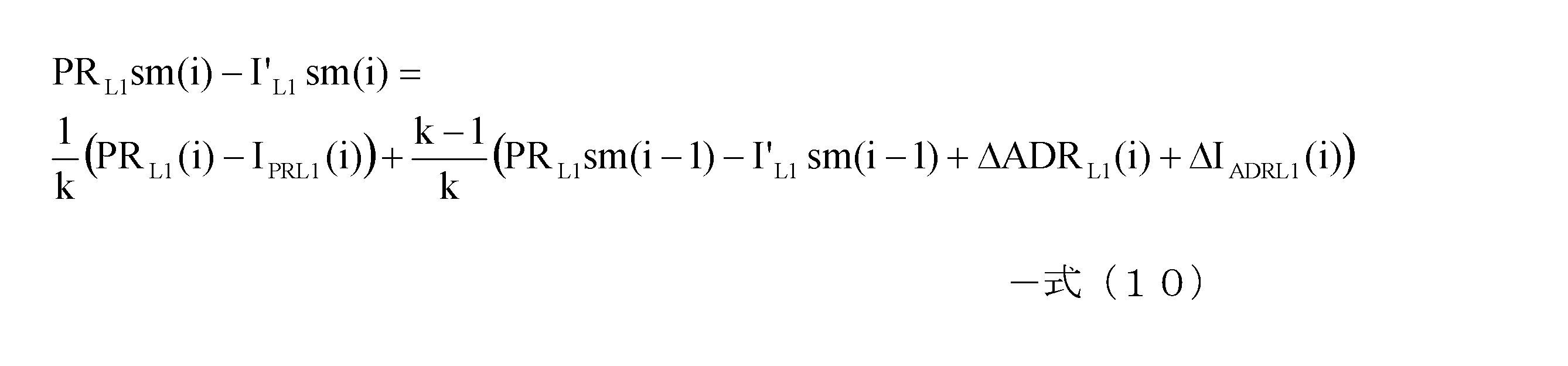
- equation (12) which means that the L1 code pseudorange is corrected by the ionospheric delay with the code ionosphere delay, is obtained.
- the time change amount ⁇ I ADRL1 (i) of the carrier ionosphere delay included in the time change amount ⁇ ADR L1 (i) of the L1 carrier phase corresponding to the first carrier ionosphere delay of the present invention is the second carrier of the present invention. It is canceled by the carrier ionospheric delay time variation ⁇ I ADRL1 (i) included in the carrier correction formula of the code ionospheric delay I PRL1 (i) corresponding to the ionospheric delay.
- the term (1 / k) ⁇ (PR L1 (i) ⁇ I PRL1 (i)) on the right side of the equation (12) indicates that the current L1 code pseudorange PR L1 (i) is the current code ionospheric delay. This corresponds to the ionospheric delay corrected by I PRL1 (i).
- the term ((k ⁇ 1) / k) ⁇ (PR L1 sm (i ⁇ 1) ⁇ I ′ L1 sm (i ⁇ 1)) is expressed as the L1 code pseudorange PR L1 sm ( This corresponds to the correction of i ⁇ 1) by the ionospheric delay I ′ L1 sm (i ⁇ 1) after the previous carrier correction.
- the code pseudorange correction unit 19 is the code pseudorange carrier smoothing unit 191, the code ionosphere delay backside correction unit 192, and the code pseudorange ionosphere delay correction unit 193, and the L1 pseudorange calculation unit 13,
- the carrier phase calculation unit for L1, the pseudorange calculation unit for L2, the carrier phase calculation unit for L2, the code ionosphere delay calculation unit 17, and the carrier ionosphere delay calculation unit 18 are shown as individual functional units, These may be used as one code pseudo distance generation unit to correct the code pseudo distance according to the following flow.
- FIG. 2 is a flowchart showing a correction process flow of the code pseudorange of the satellite navigation apparatus 1 of the present embodiment.
- the code pseudo distance generation unit calculates the L1 code pseudo distance PR L1 (i) and the L2 code pseudo distance PR L2 (i) at every predetermined timing based on the navigation message or the like (S101).
- the code pseudo-range generation unit calculates the L1 carrier phase ADR L1 (i) based on the carrier phase information of the L1 signal, and calculates the L2 carrier phase ADR L2 (i) based on the carrier phase information of the L2 signal ( S102).
- the code pseudo-range generating unit calculates the L1 code ionospheric delay I PRL1 (i) at each timing using the above-described equation (6) (S103). In addition, the code pseudo-range generation unit calculates the time variation ⁇ I ADRL1 (i) of the carrier ionospheric delay at each timing using the above-described equation (7) (S104).
- the code pseudo-range generation unit uses the above-described equations (8), (9), and (10) to change the carrier phase time variation ⁇ ADR L1 , the code ionosphere delay I PRL1 , and the carrier ionosphere delay time variation.
- ⁇ I ADRL1 ionospheric delay correction of the carrier-smoothed L1 code pseudorange PR L1 is performed (S105).
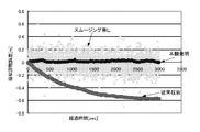
- FIG. 3 is a graph showing the value of the L1 code pseudo distance when the method of the present embodiment is used, when the conventional method is used, and when carrier smoothing is not performed.
- the horizontal axis represents the elapsed time
- the vertical axis represents the pseudorange error from the true pseudorange.
- the code pseudo distance corrected by the ionospheric delay after the carrier smoothing and the carrier correction is true even if time does not vary.
- the code pseudo-range is approximately the same.
- the code pseudo distance calculated in this way is given to the positioning calculation unit 20.
- the positioning calculation unit 20 performs positioning of the own device (receiver) by a known method using the code pseudo distance. Thereby, highly accurate positioning can be performed. Further, by providing the positioning calculation unit 20 with a reference signal generation circuit, it is possible to output a reference signal such as 1 PPS. At this time, since the code pseudo distance with high accuracy is obtained, the clock offset of the own device (receiver) can be acquired with high accuracy, so that a highly accurate reference signal can be generated.
- the code pseudo distance including the ionospheric delay can be corrected with high accuracy, and it is not necessary to use ionosphere-free coupling.
- the code pseudorange can be corrected with high accuracy using the above-described method.
- FIG. 2 is a block diagram showing a main configuration of a satellite navigation apparatus 1 according to the present embodiment, and a block diagram showing a main configuration of a code pseudorange correction unit 19. It is a flowchart which shows the correction
- 1-satellite navigation device 11-L1 receiver, 12-L2 receiver, 13-L1 pseudorange calculator, 14-L1 carrier phase calculator, 15-L2 pseudorange calculator, 16-L2 Carrier phase calculation unit, 17-code ionosphere delay calculation unit, 13-carrier ionosphere delay calculation unit, 19-code pseudorange correction unit, 191-code pseudorange carrier smoothing unit, 192-code ionosphere delay carrier correction unit, 193- Code pseudorange ionosphere delay correction unit, 20-position calculation unit, 100-antenna
Landscapes
- Engineering & Computer Science (AREA)
- Radar, Positioning & Navigation (AREA)
- Remote Sensing (AREA)
- Computer Networks & Wireless Communication (AREA)
- Physics & Mathematics (AREA)
- General Physics & Mathematics (AREA)
- Position Fixing By Use Of Radio Waves (AREA)
Abstract
Description



式(4)を式(3)に代入すると、式(5)となる。

図1(A)は本実施形態の衛星航法装置1の主要構成を示すブロック図であり、図1(B)は図1(A)に示すコード擬似距離補正部19の主要構成を示すブロック図である。
図1に示すように、本実施形態の衛星航法装置1は、L1用受信部11、L2用受信部12、L1用擬似距離算出部13、L1用キャリア位相算出部14、L2用擬似距離算出部15、L2用キャリア位相算出部16、コード電離層遅延算出部17、キャリア電離層遅延算出部18、コード擬似距離補正部19、および測位演算部20を備える。




ΔADRL1(i)=Δr(i)-ΔIADRL1(i) -式(11)
で表される。

図3に示すように、本実施形態の手法を用いることで、キャリアスムージングおよびキャリア補正後の電離層遅延による補正を行ったコード擬似距離は、時間が経過しても、値がバラつくことなく真のコード擬似距離に略一致する。
Claims (4)
- 航法衛星からの航法信号に基づいてコード擬似距離を算出する衛星航法装置であって、
キャリア位相に基づいてスムージングしたコード擬似距離を、コード電離層遅延で電離層遅延補正することで、コード擬似距離の補正を行う擬似距離補正手段を備え、
該擬似距離補正手段は、前記キャリア位相に含まれるキャリア電離層遅延と、前記コード電離層遅延の遅延方向を一致させて、前記コード擬似距離の補正を行う、衛星航法装置。 - 前記擬似距離補正手段は、前記コード擬似距離のスムージングに用いるキャリア位相に含まれる第1のキャリア電離層遅延による前記キャリア位相のズレ方向と、前記電離層遅延に用いるコード電離層遅延をキャリア補正する第2のキャリア電離層遅延の補正方向とを一致させることで、前記キャリア位相に含まれるキャリア電離層遅延と、前記コード電離層遅延の遅延方向を一致させる、請求項1に記載の衛星航法装置。
- 前記擬似距離補正手段により補正されたコード擬似距離を用いて測位演算を行う測位演算手段を備えた、請求項1または請求項2に記載の衛星航法装置。
- 前記測位演算により得られるクロックオフセットを用いて基準クロック信号を発生する基準信号発生手段を備えた、請求項3に記載の衛星航法装置。
Priority Applications (3)
| Application Number | Priority Date | Filing Date | Title |
|---|---|---|---|
| US13/126,434 US8922429B2 (en) | 2008-10-28 | 2009-10-26 | Satellite navigation device |
| CN200980142809.5A CN102197317B (zh) | 2008-10-28 | 2009-10-26 | 卫星导航装置 |
| JP2010535779A JP5483735B2 (ja) | 2008-10-28 | 2009-10-26 | 衛星航法装置 |
Applications Claiming Priority (2)
| Application Number | Priority Date | Filing Date | Title |
|---|---|---|---|
| JP2008-276842 | 2008-10-28 | ||
| JP2008276842 | 2008-10-28 |
Publications (1)
| Publication Number | Publication Date |
|---|---|
| WO2010050433A1 true WO2010050433A1 (ja) | 2010-05-06 |
Family
ID=42128795
Family Applications (1)
| Application Number | Title | Priority Date | Filing Date |
|---|---|---|---|
| PCT/JP2009/068333 Ceased WO2010050433A1 (ja) | 2008-10-28 | 2009-10-26 | 衛星航法装置 |
Country Status (4)
| Country | Link |
|---|---|
| US (1) | US8922429B2 (ja) |
| JP (1) | JP5483735B2 (ja) |
| CN (1) | CN102197317B (ja) |
| WO (1) | WO2010050433A1 (ja) |
Cited By (7)
| Publication number | Priority date | Publication date | Assignee | Title |
|---|---|---|---|---|
| CN102565816A (zh) * | 2010-12-31 | 2012-07-11 | 和芯星通科技(北京)有限公司 | 一种载波平滑伪距分组平滑方法和装置 |
| CN102565813A (zh) * | 2010-12-31 | 2012-07-11 | 和芯星通科技(北京)有限公司 | 一种通过载波平滑进行伪距观测量估计的方法和装置 |
| JP2012211795A (ja) * | 2011-03-31 | 2012-11-01 | Hitachi Zosen Corp | 海面における中周期波の計測方法および計測装置 |
| CN104516006A (zh) * | 2014-11-07 | 2015-04-15 | 中国电子科技集团公司第二十研究所 | 一种基于改进型卡尔曼滤波的载波相位平滑伪距算法 |
| JP2019045499A (ja) * | 2017-09-01 | 2019-03-22 | 末雄 杉本 | 測位装置、測位方法、測位プログラム、測位プログラム記憶媒体、アプリケーション装置、および、測位システム |
| CN111399018A (zh) * | 2020-03-02 | 2020-07-10 | 和芯星通科技(北京)有限公司 | Gnss中载波相位的平滑处理方法和装置 |
| JP2023532394A (ja) * | 2020-05-19 | 2023-07-28 | クゥアルコム・インコーポレイテッド | ユーザ機器測位信号測定および/または送信 |
Families Citing this family (10)
| Publication number | Priority date | Publication date | Assignee | Title |
|---|---|---|---|---|
| US10365375B2 (en) * | 2011-06-29 | 2019-07-30 | Raytheon Company | Method and apparatus for ionosphere depletion detection |
| US9671501B2 (en) * | 2012-09-26 | 2017-06-06 | Trimble Inc. | Global navigation satellite systems (GNSS) positioning using precise satellite data |
| US11061142B2 (en) * | 2013-05-29 | 2021-07-13 | The Boeing Company | Determining ionospheric time delays for global positioning system (GPS) receivers using multiple carrier frequencies |
| EP3137923B1 (en) * | 2014-05-02 | 2021-08-18 | Trimble Inc. | Dead reckoning system based on locally measured movement |
| CN104298860B (zh) * | 2014-09-22 | 2017-04-12 | 中国科学院国家授时中心 | 一种geo卫星转发信号码和载波相位偏差的计算方法 |
| CN104459737A (zh) * | 2014-12-02 | 2015-03-25 | 东南大学 | 一种基于信标实时差分的卫星定位方法 |
| EP3035080B1 (en) * | 2014-12-16 | 2022-08-31 | Trimble Inc. | Navigation satellite system positioning involving the generation of correction information |
| FR3049354B1 (fr) * | 2016-03-25 | 2018-03-16 | Thales | Procede de geopositionnement par satellites et terminal associe |
| CN113534213B (zh) * | 2021-07-26 | 2022-06-10 | 中国电子科技集团公司第五十四研究所 | 一种公里级区域大气相位不一致性高精度建模与修正方法 |
| CN116106936B (zh) * | 2023-04-13 | 2023-07-14 | 中国铁塔股份有限公司 | 坝体的监测信息的生成方法、定位信号传输方法和装置 |
Citations (3)
| Publication number | Priority date | Publication date | Assignee | Title |
|---|---|---|---|---|
| JPH06289116A (ja) * | 1993-02-01 | 1994-10-18 | Magnavox Electron Syst Co | 広域測位システムコード測定値平滑化方法と装置 |
| JP2002196060A (ja) * | 2000-12-25 | 2002-07-10 | Furuno Electric Co Ltd | キャリアスムージングディファレンシャル測位装置 |
| JP2006010573A (ja) * | 2004-06-28 | 2006-01-12 | Furuno Electric Co Ltd | キャリアスムージング測位装置 |
Family Cites Families (5)
| Publication number | Priority date | Publication date | Assignee | Title |
|---|---|---|---|---|
| JP3930187B2 (ja) * | 1999-03-03 | 2007-06-13 | 株式会社日立コミュニケーションテクノロジー | 同期制御方法、受信機、基地局及び移動端末 |
| US6198430B1 (en) * | 1999-03-26 | 2001-03-06 | Rockwell Collins, Inc. | Enhanced differential GNSS carrier-smoothed code processing using dual frequency measurements |
| JP2007278708A (ja) | 2006-04-03 | 2007-10-25 | Japan Radio Co Ltd | 衛星航法装置 |
| JP2008051567A (ja) | 2006-08-23 | 2008-03-06 | Japan Radio Co Ltd | 衛星航法装置 |
| FR2913773B1 (fr) * | 2007-03-16 | 2014-08-01 | Thales Sa | Dispositif de reception de signaux satellitaires comprenant une boucle de phase avec compensation des retards |
-
2009
- 2009-10-26 CN CN200980142809.5A patent/CN102197317B/zh not_active Expired - Fee Related
- 2009-10-26 JP JP2010535779A patent/JP5483735B2/ja not_active Expired - Fee Related
- 2009-10-26 WO PCT/JP2009/068333 patent/WO2010050433A1/ja not_active Ceased
- 2009-10-26 US US13/126,434 patent/US8922429B2/en not_active Expired - Fee Related
Patent Citations (3)
| Publication number | Priority date | Publication date | Assignee | Title |
|---|---|---|---|---|
| JPH06289116A (ja) * | 1993-02-01 | 1994-10-18 | Magnavox Electron Syst Co | 広域測位システムコード測定値平滑化方法と装置 |
| JP2002196060A (ja) * | 2000-12-25 | 2002-07-10 | Furuno Electric Co Ltd | キャリアスムージングディファレンシャル測位装置 |
| JP2006010573A (ja) * | 2004-06-28 | 2006-01-12 | Furuno Electric Co Ltd | キャリアスムージング測位装置 |
Cited By (10)
| Publication number | Priority date | Publication date | Assignee | Title |
|---|---|---|---|---|
| CN102565816A (zh) * | 2010-12-31 | 2012-07-11 | 和芯星通科技(北京)有限公司 | 一种载波平滑伪距分组平滑方法和装置 |
| CN102565813A (zh) * | 2010-12-31 | 2012-07-11 | 和芯星通科技(北京)有限公司 | 一种通过载波平滑进行伪距观测量估计的方法和装置 |
| JP2012211795A (ja) * | 2011-03-31 | 2012-11-01 | Hitachi Zosen Corp | 海面における中周期波の計測方法および計測装置 |
| CN104516006A (zh) * | 2014-11-07 | 2015-04-15 | 中国电子科技集团公司第二十研究所 | 一种基于改进型卡尔曼滤波的载波相位平滑伪距算法 |
| JP2019045499A (ja) * | 2017-09-01 | 2019-03-22 | 末雄 杉本 | 測位装置、測位方法、測位プログラム、測位プログラム記憶媒体、アプリケーション装置、および、測位システム |
| JP7329814B2 (ja) | 2017-09-01 | 2023-08-21 | 末雄 杉本 | 測位装置、測位方法、測位プログラム、測位プログラム記憶媒体、アプリケーション装置、および、測位システム |
| CN111399018A (zh) * | 2020-03-02 | 2020-07-10 | 和芯星通科技(北京)有限公司 | Gnss中载波相位的平滑处理方法和装置 |
| CN111399018B (zh) * | 2020-03-02 | 2022-04-01 | 和芯星通科技(北京)有限公司 | Gnss中载波相位的平滑处理方法和装置 |
| JP2023532394A (ja) * | 2020-05-19 | 2023-07-28 | クゥアルコム・インコーポレイテッド | ユーザ機器測位信号測定および/または送信 |
| JP7505030B2 (ja) | 2020-05-19 | 2024-06-24 | クゥアルコム・インコーポレイテッド | ユーザ機器測位信号測定および/または送信 |
Also Published As
| Publication number | Publication date |
|---|---|
| JP5483735B2 (ja) | 2014-05-07 |
| CN102197317A (zh) | 2011-09-21 |
| US20110205116A1 (en) | 2011-08-25 |
| US8922429B2 (en) | 2014-12-30 |
| JPWO2010050433A1 (ja) | 2012-03-29 |
| CN102197317B (zh) | 2013-06-05 |
Similar Documents
| Publication | Publication Date | Title |
|---|---|---|
| JP5483735B2 (ja) | 衛星航法装置 | |
| CN108241161B (zh) | 用于载波范围模糊度估计的分布式卡尔曼滤波器架构 | |
| CN100437142C (zh) | 基于地基增强系统的电离层延迟误差分离方法及地基增强系统 | |
| JP5968998B2 (ja) | 測位信号検出方法、測位信号検出プログラム、測位信号受信装置、測位装置および情報機器端末 | |
| CN110221325B (zh) | 一种用于伪距差分定位的误差修正方法及装置 | |
| JP2017173327A (ja) | 衛星測位システムを用いた測位方法および測位装置 | |
| JP7329814B2 (ja) | 測位装置、測位方法、測位プログラム、測位プログラム記憶媒体、アプリケーション装置、および、測位システム | |
| CN105527635A (zh) | 一种捕获微弱信号的方法和装置 | |
| WO2015194527A1 (ja) | 変換装置及びプログラム | |
| JP2014085204A (ja) | 精密測位システム、精密測位装置、精密測位方法 | |
| CN110988932A (zh) | 一种提高星载gps接收机实时钟差解算精度的方法 | |
| JP4983699B2 (ja) | Gnss測位装置及び方法 | |
| JP2014238349A (ja) | 測位装置、情報機器端末、測位システム、測位方法、および測位プログラム | |
| JP2009025045A (ja) | 移動体用測位装置 | |
| JP2005069866A (ja) | 相対測位装置 | |
| EP4318047A1 (en) | Position measurement apparatus, position measurement program, and position measurement method | |
| JP2013253814A (ja) | 測位方法、測位プログラム、測位装置、および情報機器端末 | |
| KR20250037490A (ko) | 모션-보상된 신호 처리를 수행하는 방법 및 장치 | |
| KR102231874B1 (ko) | 주파수별 위성항법 보정정보를 산출하는 장치 및 그 방법 | |
| WO2006101078A1 (ja) | 測位装置 | |
| JP2007127579A (ja) | キャリア位相相対測位装置 | |
| JP2007278708A (ja) | 衛星航法装置 | |
| JP7014400B2 (ja) | 測位装置、測位方法、測位プログラム、測位プログラム記憶媒体、アプリケーション装置、および、測位システム | |
| JP7001875B2 (ja) | 測位装置及び補強情報生成装置 | |
| JP2008082819A (ja) | 測位装置および測位方法 |
Legal Events
| Date | Code | Title | Description |
|---|---|---|---|
| WWE | Wipo information: entry into national phase |
Ref document number: 200980142809.5 Country of ref document: CN |
|
| 121 | Ep: the epo has been informed by wipo that ep was designated in this application |
Ref document number: 09823543 Country of ref document: EP Kind code of ref document: A1 |
|
| ENP | Entry into the national phase |
Ref document number: 2010535779 Country of ref document: JP Kind code of ref document: A |
|
| WWE | Wipo information: entry into national phase |
Ref document number: 13126434 Country of ref document: US |
|
| NENP | Non-entry into the national phase |
Ref country code: DE |
|
| 122 | Ep: pct application non-entry in european phase |
Ref document number: 09823543 Country of ref document: EP Kind code of ref document: A1 |