WO2010050388A1 - 切屑回収式切削工具 - Google Patents
切屑回収式切削工具 Download PDFInfo
- Publication number
- WO2010050388A1 WO2010050388A1 PCT/JP2009/068097 JP2009068097W WO2010050388A1 WO 2010050388 A1 WO2010050388 A1 WO 2010050388A1 JP 2009068097 W JP2009068097 W JP 2009068097W WO 2010050388 A1 WO2010050388 A1 WO 2010050388A1
- Authority
- WO
- WIPO (PCT)
- Prior art keywords
- shank
- chip
- blind hole
- main body
- cutting tool
- Prior art date
- Legal status (The legal status is an assumption and is not a legal conclusion. Google has not performed a legal analysis and makes no representation as to the accuracy of the status listed.)
- Ceased
Links
Images



Classifications
-
- B—PERFORMING OPERATIONS; TRANSPORTING
- B23—MACHINE TOOLS; METAL-WORKING NOT OTHERWISE PROVIDED FOR
- B23B—TURNING; BORING
- B23B51/00—Tools for drilling machines
- B23B51/02—Twist drills
-
- B—PERFORMING OPERATIONS; TRANSPORTING
- B23—MACHINE TOOLS; METAL-WORKING NOT OTHERWISE PROVIDED FOR
- B23C—MILLING
- B23C5/00—Milling-cutters
- B23C5/006—Details of the milling cutter body
-
- B—PERFORMING OPERATIONS; TRANSPORTING
- B23—MACHINE TOOLS; METAL-WORKING NOT OTHERWISE PROVIDED FOR
- B23C—MILLING
- B23C5/00—Milling-cutters
- B23C5/02—Milling-cutters characterised by the shape of the cutter
- B23C5/10—Shank-type cutters, i.e. with an integral shaft
-
- B—PERFORMING OPERATIONS; TRANSPORTING
- B23—MACHINE TOOLS; METAL-WORKING NOT OTHERWISE PROVIDED FOR
- B23B—TURNING; BORING
- B23B2251/00—Details of tools for drilling machines
- B23B2251/68—Drills with provision for suction
-
- B—PERFORMING OPERATIONS; TRANSPORTING
- B23—MACHINE TOOLS; METAL-WORKING NOT OTHERWISE PROVIDED FOR
- B23B—TURNING; BORING
- B23B2270/00—Details of turning, boring or drilling machines, processes or tools not otherwise provided for
- B23B2270/30—Chip guiding or removal
-
- B—PERFORMING OPERATIONS; TRANSPORTING
- B23—MACHINE TOOLS; METAL-WORKING NOT OTHERWISE PROVIDED FOR
- B23C—MILLING
- B23C2230/00—Details of chip evacuation
- B23C2230/04—Transport of chips
- B23C2230/045—Transport of chips to the middle of the cutter or in the middle of a hollow cutter
-
- B—PERFORMING OPERATIONS; TRANSPORTING
- B23—MACHINE TOOLS; METAL-WORKING NOT OTHERWISE PROVIDED FOR
- B23C—MILLING
- B23C2230/00—Details of chip evacuation
- B23C2230/08—Using suction
Definitions
- This invention relates to a rotary cutting tool such as a ball end mill.
- the present invention relates to a chip recovery-type cutting tool that allows forced recovery of chips through an air flow inside a main body.
- Patent Document 1 As a conventional example of the above-mentioned cutting tool having a function of forcibly collecting chips, there is one disclosed in Patent Document 1 below.
- a cutting tool unit ball end mill
- a cutting tool having a cutting groove and a chip groove serving as a chip pocket is attached to a cylindrical holder by shrink fitting.
- a suction path is formed between the chip groove and the holder, and cutting is performed while suctioning and collecting chips scraped by the cutting blade through the suction path.
- the cutting tool unit disclosed in Patent Document 1 includes a cutting tool and a holder provided with a main body having no diameter change over the entire length.
- the length of the main body portion of the cutting tool is increased to some extent, and the main body portion is inserted into the hole of the holder, and the insertion portion is tightened with the holder by shrink fitting to connect the two.
- connection between the holder and the main body of the cutting tool depends only on the frictional force of the fitting part between them. For this reason, there is a problem in the holding stability of the main body by the holder, and there is a possibility that the main body is detached from the holder in a process in which a thrust force is applied to the cutting tool.
- the amount of insertion of the main body with respect to the holder is not stable, and the amount of insertion may vary due to slipping during use. Therefore, when the tool after the insertion amount variation is used under the same conditions as before the insertion amount variation, there is a concern that the machining accuracy is lowered.
- the length of the main body inserted into the holder is long, the length of the suction path between the chip groove and the holder is inevitably long. As a result, the suction resistance increases, the intake efficiency decreases, and the chip collection efficiency decreases.
- the holder may become an obstacle and be subject to processing restrictions.
- the object of the present invention is to improve the stability of processing and improve the efficiency of chip recovery, and to make it possible to eliminate processing restrictions due to the shape of the tool as required.
- a chip recovery cutting tool A main body having a shank formed integrally with the effective blade length, and A cutting edge provided at the tip of the main body, Corresponding to the cutting edge, including a chip groove provided on the outer periphery of the effective blade length of the main body,
- the shank extends from the rear end of the shank to the front end side of the main body before the effective blade length, and is provided with a blind hole that is parallel to the axis and opened at the rear end of the shank.
- the chip groove communicates with the blind hole, and the chip scraped by the cutting blade is passed through the chip groove and the blind hole connected to the chip groove, so that the chips scraped by the cutting blade can be
- the chip collecting type cutting tool was placed in the blind hole, taken into the blind hole, and then discharged to the outside through the blind hole.
- the main body portion is composed of a head portion having a cutting edge, a chip groove and the shank, and a shank remaining portion, and the head portion is connected to the shank remaining portion so that the head portion can be replaced.
- the chip groove is arranged symmetrically about the center of rotation, and two strips are provided in the head portion.
- the groove width in the cross section perpendicular to the axis is 0.6D. It is also effective to set to ⁇ 0.8D.
- the present invention can be suitably used for a ball end mill equipped with a ball blade.
- the chip recovery type cutting tool of the present invention is formed integrally with a cutting blade, a chip groove and a shank, provided with a blind hole inside the shank, and formed in the blind hole on the outer periphery of the effective blade length of the main body.
- the chip groove was made to communicate. Therefore, by passing an air current through the chip groove and a blind hole inside the shank, the chips cut by the cutting blade can be placed in the air stream and taken into the blind hole, and the chips can be discharged from the blind hole to the outside. it can.
- the passage area of the chip discharge path is narrowed by inserting a cutting tool into the hole of the holder.
- the tool of the present invention increases the passage area of the portion constituted by the blind hole of the chip discharge passage as compared with the structure of Patent Document 1 by forming the blind hole just before the effective blade length. Can do. Therefore, an increase in airflow resistance (decrease in intake efficiency) is suppressed, and chip collection efficiency is increased.
- This structure can integrate the head part into the shank. Even when the head portion is independent from the shank remaining portion, it can be added to the shank remaining portion with a structure constrained in the axial direction. For this reason, it is possible to improve the holding stability and the positional accuracy of the head portion to stabilize the processing and improve the processing accuracy.
- the head portion and the shank are integrated, it is possible to avoid the shank diameter being larger than the diameter of the effective blade length portion. Therefore, processing restrictions due to the shank (holder) becoming an obstacle can be eliminated.
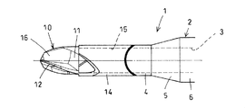
- FIG. 1 The side view which shows embodiment of the chip collection type cutting tool of this invention.
- tip part of the cutting tool of FIG. FIG. 1 is an enlarged sectional view of a portion along the line AA in FIG.
- This chip recovery type cutting tool 1 includes a head portion 10 and a shank remaining portion 2.
- the head portion 10 is formed of a cemented carbide or a material whose surface is coated with a hard material.
- the head portion 10 has a cutting edge 12 on the outer periphery of the front end of the main body portion 11.
- the cutting edge 12 of the illustrated tool is a ball blade having a substantially 1 ⁇ 4 circle in a side view, and the two blades are arranged symmetrically about the center of rotation.
- the main body 11 includes a shank 14 integrated with the effective blade length portion 13 behind the effective blade length portion 13 (that is, the tip side portion of the shank in the figure).
- the blind hole 15 is open to the rear end of the shank 14.
- a chip groove 16 corresponding to each cutting edge 12 is provided on the outer periphery of the effective blade length portion 13.
- the illustrated chip groove 16 is a torsion groove, and the inner diameter thereof is a through-hole provided in the center of the shank remainder. Is equal to the inner diameter of 3.
- the chip grooves 16 are formed to a position where they can be cut through the end walls of the blind holes 15, and the chip grooves 16 are communicated with the blind holes 15.
- the tool provided with two strips on the head portion 10 with the chip grooves 16 arranged symmetrically about the center of rotation has an effective diameter of the tool as D, and the groove width W of the chip grooves 16 in the cross section perpendicular to the axis is 0.6D.
- the passage area of the chip discharge passage can be sufficiently secured while maintaining the required strength of the main body 11.
- the chip discharge path is a passage constituted by the chip groove 16 and the blind hole 15.
- the head portion 10 is connected to the tip of the shank remaining portion 2 to form a chip recovery type cutting tool 1.
- the shank remainder 2 is made of a steel material that is cheaper than the blade material, and has a through hole 3 in the axial center.
- a large-diameter cylindrical part 6 is connected to the rear of the small-diameter cylindrical part 4 via a taper part 5, and a head part 10 is connected to the tip of the small-diameter cylindrical part 4.
- the shank remaining portion 2 has the tip outer diameter equal to the outer diameter of the effective blade length portion 13 of the tool because processing restrictions by the shank remaining portion 2 can be avoided.
- the head part 10 and the shank remaining part 2 are connected by making the outer diameter and inner diameter of the shank 14 included in the head part 10 and the small diameter cylindrical part 4 at the front end side of the shank part equal to each other, Butting is performed with the V-shaped fitting, and the butted portion is brazed and joined.
- connection structures such as screwed connection, shrink fit connection, and bayonet fitting connection can also be used.
- the connecting structure by brazing shown in the drawing is preferable.
- the chip recovery type cutting tool configured as described above is used while being held by a spindle of a processing machine or a tool holder set on the spindle in the same manner as a normal rotary cutting tool.
- the through-hole 3 of the shank remaining part 2 is communicated with the dust collecting chamber via the main shaft and the tool holder.
- the chips generated during processing by passing the air flow from the front end of the main body 11 toward the rear through the through hole 3 of the remaining shank 2, the blind hole 15 communicating with the hole, and the chip groove 16 communicating with the blind hole 15. Is put in the airflow and taken into the blind hole 15, and chips are discharged from the blind hole 15 to the outside and collected in the dust collecting chamber.
- the air flow generated in the shank and in the chip groove can be generated by suction or air blowing. Since the illustrated tool is an end mill, chip collection by suction is suitable. In the case where air injection to the periphery of the processing part is allowed, it is possible to perform pumping and recovery by discharging the injected air through the inside of the shank 2.
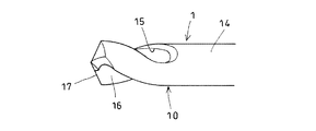
- FIG. 6 shows an example.
- the head portion 10 provided with the drill blade 17 is connected to the tip of the shank remaining portion 2.
- the cutting tools used for the evaluation were the inventive ball end mill having the structure shown in FIG. 1 and the comparative ball end mill.
- Comparison ball end mill A cutting tool provided with a chip groove on the outer periphery (effective diameter is the same as that of the invention) was inserted into the tip of the hollow shank and fixed by shrink fitting. In the test, cutting was performed under the following conditions, and at that time, chips were sucked and collected by a dust collector, and the collection state was examined.
Landscapes
- Engineering & Computer Science (AREA)
- Mechanical Engineering (AREA)
- Milling Processes (AREA)
- Drilling Tools (AREA)
Abstract
本体部(11)に有効刃長部(13)と一体のシャンク(14)を含ませ、そのシャンク(14)の内部に有効刃長部の手前まで延びる止まり穴(15)を設け、有効刃長部(13)の外周の切屑溝(16)を止まり穴(15)に連通させ、切れ刃(12)によって削られた切屑を吸引又は圧送気流に乗せて止まり穴(15)に取り込み、この止まり穴(15)から外部に排出できるようにした。
Description
この発明は、ボールエンドミルなどの回転切削工具に関する。特に、本体部の内部に気流を通して切屑の強制回収を行えるようにした切屑回収式切削工具に関する。
切屑の強制回収機能を有する首記の切削工具の従来例として、下記特許文献1に開示されたものがある。同文献に開示された切削工具ユニット(ボールエンドミル)は、切れ刃と切屑ポケットとなる切屑溝を有する切削工具を筒状ホルダに焼きばめによって取り付けている。そして、前記切屑溝とホルダとの間に吸引路が形成され、その吸引路を通じて切れ刃により削り取られた切屑を吸引回収しながら切削が行われる。
上記特許文献1が開示している切削工具ユニットは、全長に渡って径変化のない本体部を備えた切削工具とホルダを含む。その切削工具の本体部の長さはある程度長くしており、その本体部をホルダの孔に挿入し、その挿入部を焼きばめによりホルダで締付けて両者を連結する。
この切削ユニットにおいて、ホルダと切削工具の本体部の連結は、両者の嵌合部の摩擦力のみに依存する。そのため、ホルダによる本体部の保持安定性に問題があり、切削工具にスラスト力が加わる加工においては、本体部がホルダから外れる虞がある。
また、ホルダに対する本体部の挿入量が安定せず、使用中のスリップにより挿入量の変動も起こりうる。そのために、挿入量変動後の工具が挿入量変動前と同一条件で使用された場合、加工精度が低下する懸念がある。
さらに、ホルダに挿入される本体部の長さが長いため、切屑溝とホルダとの間の吸引路の長さも必然的に長くなる。その結果、吸引の抵抗が大きくなって吸気効率が低下し、切屑の回収効率が低下する。
これらに加え、ホルダが障害物となって加工上の規制を受けることもある。
この発明は、加工の安定向上と切屑の回収効率向上を図り、そして、工具の形状による加工規制も必要に応じて解消可能となすことを課題としている。
上記の課題を解決するため、この発明においては、
切屑回収式切削工具であって、
有効刃長部と一体に形成されたシャンクを有する本体部と、
本体部の先端に設けた切れ刃と、
前記切れ刃に対応し、本体部の有効刃長部の外周に設けた切屑溝を含み、
そのシャンクは、その内部にそのシャンクの後端から本体部の先端側に向って有効刃長部の手前まで延びると共に、軸心と平行であって、シャンクの後端に開放した止まり穴を設け、
前記切屑溝は前記止まり穴に連通しており、前記切屑溝とそれに通じた前記止まり穴に本体部の先端側から後端に向う気流を通すことにより、切れ刃によって削られた切屑が前記気流に乗せて前記止まり穴に取り込み、その後この止まり穴から外部に排出されるようにした切屑回収式切削工具とした。
切屑回収式切削工具であって、
有効刃長部と一体に形成されたシャンクを有する本体部と、
本体部の先端に設けた切れ刃と、
前記切れ刃に対応し、本体部の有効刃長部の外周に設けた切屑溝を含み、
そのシャンクは、その内部にそのシャンクの後端から本体部の先端側に向って有効刃長部の手前まで延びると共に、軸心と平行であって、シャンクの後端に開放した止まり穴を設け、
前記切屑溝は前記止まり穴に連通しており、前記切屑溝とそれに通じた前記止まり穴に本体部の先端側から後端に向う気流を通すことにより、切れ刃によって削られた切屑が前記気流に乗せて前記止まり穴に取り込み、その後この止まり穴から外部に排出されるようにした切屑回収式切削工具とした。
この切削工具において、本体部を、切れ刃、切屑溝および前記シャンクを有するヘッド部と、シャンク残部とで構成し、シャンク残部にヘッド部を付け替え可能に連結すると好ましい。
2枚刃の切削工具では、切屑溝を回転中心対称の配置にしてヘッド部に2条設け、工具の有効径をDとした時に、その切屑溝の軸直角断面での溝幅が0.6D~0.8Dに設定されるのも有効である。
なお、この発明はボール刃を備えたボールエンドミルなどに好適に利用することができる。
この発明の切屑回収式切削工具は、切れ刃、切屑溝およびシャンクを一体で形成し、そのシャンクの内部に止まり穴を設け、その止まり穴に本体部の有効刃長部の外周に形成された切屑溝を連通させた。そのため、前記切屑溝とそれに通じたシャンク内部の止まり穴に気流を通すことで切れ刃によって削られた切屑をその気流に乗せて止まり穴に取り込み、この止まり穴から切屑を外部に排出することができる。
前記特許文献1の構造では、ホルダの孔に切削工具が挿入されることで切屑排出路の通路面積が狭められる。それに対し、この発明の工具は、止まり穴を有効刃長部の手前まで形成したことで、特許文献1の構造に比べて切屑排出路の止まり穴で構成される部分の通路面積を増大させることができる。そのため、気流の抵抗増加(吸気効率の低下)が抑えられて切屑の回収効率が高まる。
この構造は、ヘッド部をシャンクに一体化することが可能である。ヘッド部をシャンク残部から独立させる場合にも、軸方向に拘束される構造にしてシャンク残部に継ぎ足すことができる。そのため、ヘッド部の保持安定性と位置精度を高めて加工の安定化や加工精度の向上を図ることも可能になる。
さらに、ヘッド部とシャンクが一体であるので、シャンク径が有効刃長部の直径より大きくなることを回避できる。そのため、シャンク(ホルダ)が障害物となることによる加工規制もなくすことができる。
1 切屑回収式切削工具
2 シャンク残部
3 貫通孔
4 小径円筒部
5 テーパ部
6 大径円筒部
10 ヘッド部
11 本体部
12 切れ刃
13 有効刃長部
14 シャンク
15 止まり穴
16 切屑溝
17 ドリル刃
D 工具の有効径
d 止まり穴と貫通孔の内径
W 溝幅
2 シャンク残部
3 貫通孔
4 小径円筒部
5 テーパ部
6 大径円筒部
10 ヘッド部
11 本体部
12 切れ刃
13 有効刃長部
14 シャンク
15 止まり穴
16 切屑溝
17 ドリル刃
D 工具の有効径
d 止まり穴と貫通孔の内径
W 溝幅
以下、添付図面の図1~図6に基づいて、この発明の切削工具の実施の形態を説明する。図1~図4は、ボールエンドミルへの適用例を表したものである。この切屑回収式切削工具1は、ヘッド部10とシャンク残部2で構成している。
ヘッド部10は、超硬合金や表面に硬質材をコーティングした素材で形成されている。
このヘッド部10は、本体部11の先端外周に切れ刃12を有する。図示の工具の切れ刃12は、側面視で略1/4円をなすボール刃であり、2枚の刃を回転中心対称に配置している。
このヘッド部10は、本体部11の先端外周に切れ刃12を有する。図示の工具の切れ刃12は、側面視で略1/4円をなすボール刃であり、2枚の刃を回転中心対称に配置している。
本体部11には、有効刃長部13の後方にその有効刃長部13と一体のシャンク14(図のそれはシャンクの先端側部分)を含ませている。そして、そのシャンク14の内部に、シャンク14の後面から本体部11の先端側に向って有効刃長部13の手前まで延びる軸心と平行な止まり穴15を設けている。その止まり穴15は、シャンク14の後端に開放している。
有効刃長部13の外周には、各切れ刃12に対応させた切屑溝16を設けている、図示の切屑溝16は捩れ溝であり、その内径はシャンク残部の中心に設けられた貫通孔3の内径と等しい。この切屑溝16を止まり穴15の端壁に切り抜ける位置まで形成して各切屑溝16を止まり穴15に連通させている。
図のように、切屑溝16を回転中心対称の配置にしてヘッド部10に2条設ける工具は、工具の有効径をDとして、軸直角断面での切屑溝16の溝幅Wを0.6D~0.8Dに設定すると、本体部11の必要強度を維持しながら切屑排出路の通路面積を十分に確保することができる。切屑排出路は、切屑溝16と止まり穴15によって構成される通路である。(ここまで)
このヘッド部10を、シャンク残部2の先端に連結して切屑回収式切削工具1となしている。
シャンク残部2は、刃具用素材に比べて安価な鋼材などで構成されており、軸心部に貫通孔3を有する。例示のシャンク残部2は、小径円筒部4の後方にテーパ部5を介して大径円筒部6を連設しており、小径円筒部4の先端にヘッド部10が連結される。
このシャンク残部2は、先端の外径を工具の有効刃長部13の外径と等しくしたものが、シャンク残部2による加工規制を回避できて好ましい。
ヘッド部10とシャンク残部2の連結は、ヘッド部10に含ませたシャンク14とシャンク残部の先端側小径円筒部4のそれぞれの外径と内径を等しくして、その両者の後端と先端をV字嵌合した状態で突き合わせ、その突合せ部を鑞付け接合して行っている。
ねじ込み連結や焼きばめ連結、バヨネット嵌合の連結といった他の連結構造を採用することもできる。しかし、軸直角断面での止まり穴15の断面積(切屑排出路の断面積)を広く確保できるので図示の鑞付けによる連結構造が好ましい。
以上の如く構成した切屑回収式切削工具は、通常の回転切削工具と同様に、加工機の主軸または主軸にセットされた工具ホルダで保持して使用する。このとき、シャンク残部2の貫通孔3を主軸や工具ホルダを介して集塵室に連通させる。そして、シャンク残部2の貫通孔3、その孔に連通した止まり穴15およびその止まり穴15に連通した切屑溝16に本体部11の先端から後部に向う気流を通すことにより、加工時に発生した切屑をその気流に乗せて止まり穴15に取り込み、この止まり穴15から切屑を外部に排出して集塵室に回収する。
シャンクの内部と切屑溝に発生させる気流は、吸引やエアーの吹き込みによって生じさせることができる。図示の工具は、エンドミルであるので吸引による切屑回収が適している。加工部周辺へのエアー噴射が許容される場合には、噴射したエアーをシャンク2の内部に通して排出することで、圧送回収を行うこともできる。
なお、上記の説明はボールエンドミルを例に挙げて行った。この発明では気流を利用して切屑の強制回収を行うので、ヘッドピースの先端に複数の切れ刃を有するスクエアエンドミル、ラジアスエンドミルまたはドリルに適用することも可能である。図6はその例を示したものである。ドリル刃17を設けたヘッド部10をシャンク残部2の先端に連結している。
この発明の効果の確認のために評価試験を行った。
評価に使用した切削工具は、図1の構造の発明品のボールエンドミルと比較品のボールエンドミルである。
・発明品のボールエンドミル:
ヘッド部をシャンク残部の先端に鑞付け接合した工具有効径D=φ10mm、
止まり穴と貫通孔の内径d=φ9mm
・比較品のボールエンドミル:
外周に切屑溝を設けた切削工具(有効径は発明品と同じ)を中空シャンクの先端に挿入して焼きばめにより固定した。
試験は、下記の条件で切削を行い、そのときに集塵機による切屑の吸引回収を行って回収状況を調べた。
被削材:カーボン
-切削条件-
切削速度Vc:157m/min
一刃当たり送り量fz:0.125/刃
切込みap:3mm
切削幅ae:3mm
ダウンカット
ドライ切削
集塵機能力:発明品1.6kW
比較品1.7kW
評価に使用した切削工具は、図1の構造の発明品のボールエンドミルと比較品のボールエンドミルである。
・発明品のボールエンドミル:
ヘッド部をシャンク残部の先端に鑞付け接合した工具有効径D=φ10mm、
止まり穴と貫通孔の内径d=φ9mm
・比較品のボールエンドミル:
外周に切屑溝を設けた切削工具(有効径は発明品と同じ)を中空シャンクの先端に挿入して焼きばめにより固定した。
試験は、下記の条件で切削を行い、そのときに集塵機による切屑の吸引回収を行って回収状況を調べた。
被削材:カーボン
-切削条件-
切削速度Vc:157m/min
一刃当たり送り量fz:0.125/刃
切込みap:3mm
切削幅ae:3mm
ダウンカット
ドライ切削
集塵機能力:発明品1.6kW
比較品1.7kW
この試験の結果、発明品は安定した加工と、比較品よりも優れた切屑回収がなされることを確認した。
Claims (3)
- 切屑回収式切削工具であって、
有効刃長部(13)と一体に形成されたシャンク(14)を有する本体部(11)と
前記本体部(11)の先端に設けた切れ刃(12)と、
前記切れ刃(12)に対応し、前記本体部(11)の前記有効刃長部(13)の外周に設けた切屑溝(16)を含み、
前記シャンク(14)は、内部に、シャンクの後面から本体部の先端側に向って有効刃長部(13)の手前まで延びると共に、軸心と平行であって、シャンクの後端に開放した止まり穴(15)を有し、
前記切屑溝(16)は、前記止まり穴(15)に連通しており、前記切屑溝(16)とそれに通じた前記止まり穴(15)に本体部の先端側から後端に向う気流を通すことにより、切れ刃(12)によって削られた切屑が前記気流に乗せて前記止まり穴(15)に取り込まれ、その後この止まり穴(15)から外部に排出されるようにした切屑回収式切削工具。 - 前記本体部(11)は、前記切れ刃(12)、前記切屑溝(16)および前記シャンク(14)を有するヘッド部(10)と、シャンク残部(2)とを含み、
前記シャンク残部(2)に前記ヘッド部(10)を着け替え可能に連結した請求項1に記載の切屑回収式切削工具。 - 前記切屑溝(16)を回転中心対称の配置にして前記ヘッド部(10)に2条設け、工具の有効径をDとした時に、その切屑溝(16)の軸直角断面での溝幅(W)を0.6D~0.8Dに設定した請求項1又は2に記載の切屑回収式切削工具。
Applications Claiming Priority (2)
| Application Number | Priority Date | Filing Date | Title |
|---|---|---|---|
| JP2008-278010 | 2008-10-29 | ||
| JP2008278010A JP2010105096A (ja) | 2008-10-29 | 2008-10-29 | 切屑回収式切削工具 |
Publications (1)
| Publication Number | Publication Date |
|---|---|
| WO2010050388A1 true WO2010050388A1 (ja) | 2010-05-06 |
Family
ID=42128753
Family Applications (1)
| Application Number | Title | Priority Date | Filing Date |
|---|---|---|---|
| PCT/JP2009/068097 Ceased WO2010050388A1 (ja) | 2008-10-29 | 2009-10-21 | 切屑回収式切削工具 |
Country Status (2)
| Country | Link |
|---|---|
| JP (1) | JP2010105096A (ja) |
| WO (1) | WO2010050388A1 (ja) |
Cited By (4)
| Publication number | Priority date | Publication date | Assignee | Title |
|---|---|---|---|---|
| DE102013205363A1 (de) * | 2013-03-26 | 2014-10-02 | Kennametal Inc. | Werkzeugkopf sowie Verfahren zur Bearbeitung eines metallischen Werkstücks |
| EP2572849A4 (en) * | 2010-05-21 | 2017-11-08 | Kabushiki Kaisha Miyanaga | Drill bit |
| US20200246923A1 (en) * | 2017-08-03 | 2020-08-06 | Vestas Wind Systems A/S | Mill bit for the manufacture of a wind turbine blade and method of forming same |
| US20220266357A1 (en) * | 2019-08-09 | 2022-08-25 | Kamen Petrov Kamenov | Milling bit with spherical ending for cnc milling of industrial clay |
Families Citing this family (2)
| Publication number | Priority date | Publication date | Assignee | Title |
|---|---|---|---|---|
| JP6400887B2 (ja) * | 2013-06-10 | 2018-10-03 | 株式会社Subaru | 切削工具及び切削工具の製造方法 |
| JP6835194B1 (ja) | 2019-12-12 | 2021-02-24 | 株式会社タンガロイ | 穴あけ工具 |
Citations (5)
| Publication number | Priority date | Publication date | Assignee | Title |
|---|---|---|---|---|
| JPH08141813A (ja) * | 1994-11-22 | 1996-06-04 | Mitsubishi Materials Corp | ドリル |
| JPH08168913A (ja) * | 1992-04-03 | 1996-07-02 | Hitachi Tool Eng Ltd | ボールエンドミル |
| WO2002005990A1 (en) * | 2000-07-14 | 2002-01-24 | Sumitomo Electric Industries, Ltd. | Throw-away cutting tool |
| JP2008173705A (ja) * | 2007-01-17 | 2008-07-31 | Osg Corp | 切削工具ユニット及びその切削工具ユニットに使用される切削工具 |
| WO2008123219A1 (ja) * | 2007-04-02 | 2008-10-16 | Unitac Incorporated | 深穴切削装置 |
Family Cites Families (3)
| Publication number | Priority date | Publication date | Assignee | Title |
|---|---|---|---|---|
| JPH0618732Y2 (ja) * | 1988-09-02 | 1994-05-18 | 東芝タンガロイ株式会社 | ボールエンドミル |
| JPH04269112A (ja) * | 1991-02-19 | 1992-09-25 | Hitachi Tool Eng Ltd | オイルホール付きエンドミル |
| JP2525893Y2 (ja) * | 1992-06-17 | 1997-02-12 | 株式会社牧野フライス製作所 | 切削工具 |
-
2008
- 2008-10-29 JP JP2008278010A patent/JP2010105096A/ja active Pending
-
2009
- 2009-10-21 WO PCT/JP2009/068097 patent/WO2010050388A1/ja not_active Ceased
Patent Citations (5)
| Publication number | Priority date | Publication date | Assignee | Title |
|---|---|---|---|---|
| JPH08168913A (ja) * | 1992-04-03 | 1996-07-02 | Hitachi Tool Eng Ltd | ボールエンドミル |
| JPH08141813A (ja) * | 1994-11-22 | 1996-06-04 | Mitsubishi Materials Corp | ドリル |
| WO2002005990A1 (en) * | 2000-07-14 | 2002-01-24 | Sumitomo Electric Industries, Ltd. | Throw-away cutting tool |
| JP2008173705A (ja) * | 2007-01-17 | 2008-07-31 | Osg Corp | 切削工具ユニット及びその切削工具ユニットに使用される切削工具 |
| WO2008123219A1 (ja) * | 2007-04-02 | 2008-10-16 | Unitac Incorporated | 深穴切削装置 |
Cited By (8)
| Publication number | Priority date | Publication date | Assignee | Title |
|---|---|---|---|---|
| EP2572849A4 (en) * | 2010-05-21 | 2017-11-08 | Kabushiki Kaisha Miyanaga | Drill bit |
| DE102013205363A1 (de) * | 2013-03-26 | 2014-10-02 | Kennametal Inc. | Werkzeugkopf sowie Verfahren zur Bearbeitung eines metallischen Werkstücks |
| US9415450B2 (en) | 2013-03-26 | 2016-08-16 | Kennametal Inc. | Tool head and method for machining a metallic workpiece |
| DE102013205363B4 (de) | 2013-03-26 | 2022-01-05 | Kennametal Inc. | Werkzeugkopf sowie Verfahren zur Bearbeitung eines metallischen Werkstücks |
| US20200246923A1 (en) * | 2017-08-03 | 2020-08-06 | Vestas Wind Systems A/S | Mill bit for the manufacture of a wind turbine blade and method of forming same |
| US11926005B2 (en) * | 2017-08-03 | 2024-03-12 | Vestas Wind Systems A/S | Mill bit for the manufacture of a wind turbine blade and method of forming same |
| US20220266357A1 (en) * | 2019-08-09 | 2022-08-25 | Kamen Petrov Kamenov | Milling bit with spherical ending for cnc milling of industrial clay |
| US12440905B2 (en) * | 2019-08-09 | 2025-10-14 | Kamen Petrov Kamenov | Milling bit with spherical ending for CNC milling of industrial clay |
Also Published As
| Publication number | Publication date |
|---|---|
| JP2010105096A (ja) | 2010-05-13 |
Similar Documents
| Publication | Publication Date | Title |
|---|---|---|
| JP4671968B2 (ja) | ツイストドリル | |
| JP5951113B2 (ja) | 切削液供給穴付3枚刃ドリル | |
| KR101455582B1 (ko) | 칩 흡인 솔리드 드릴 | |
| JP4802095B2 (ja) | ドリル | |
| WO2010050388A1 (ja) | 切屑回収式切削工具 | |
| JP4860631B2 (ja) | ドリル | |
| WO2014118881A1 (ja) | ドリル | |
| TW200800445A (en) | Deep-hole drilling apparatus | |
| CN1332777C (zh) | 用于切屑形成加工的工具 | |
| WO2006132068A1 (ja) | 深孔加工用ドリルヘッド | |
| JP2008093805A (ja) | ドリル | |
| JP5271450B2 (ja) | ドリルビット | |
| CN110023013A (zh) | 麻花钻和用于麻花钻的可更换头部 | |
| US20110067927A1 (en) | Drill Head for Deep-Hole Drilling | |
| JPWO2008068818A1 (ja) | エンドミル | |
| JP5675524B2 (ja) | 切削加工用工具 | |
| JP5218838B2 (ja) | 切屑回収式切削工具 | |
| JP4969255B2 (ja) | ドリルユニット並びにそのドリルユニットに使用されるドリル及びホルダ | |
| US20100247259A1 (en) | Drill bit | |
| JP2015112732A (ja) | ドリルビット | |
| JP4699526B2 (ja) | ドリル | |
| EP4335578A1 (en) | Collet bush and tool driving device | |
| CN103358404B (zh) | 钻削工具及其钻头 | |
| JP4954044B2 (ja) | ドリル | |
| JP4805978B2 (ja) | 切削工具、工作機械および加工方法 |
Legal Events
| Date | Code | Title | Description |
|---|---|---|---|
| 121 | Ep: the epo has been informed by wipo that ep was designated in this application |
Ref document number: 09823500 Country of ref document: EP Kind code of ref document: A1 |
|
| NENP | Non-entry into the national phase |
Ref country code: DE |
|
| 122 | Ep: pct application non-entry in european phase |
Ref document number: 09823500 Country of ref document: EP Kind code of ref document: A1 |