WO2010050147A1 - 電気コネクタ - Google Patents
電気コネクタ Download PDFInfo
- Publication number
- WO2010050147A1 WO2010050147A1 PCT/JP2009/005494 JP2009005494W WO2010050147A1 WO 2010050147 A1 WO2010050147 A1 WO 2010050147A1 JP 2009005494 W JP2009005494 W JP 2009005494W WO 2010050147 A1 WO2010050147 A1 WO 2010050147A1
- Authority
- WO
- WIPO (PCT)
- Prior art keywords
- tine plate
- tine
- contact
- housing
- contacts
- Prior art date
- Legal status (The legal status is an assumption and is not a legal conclusion. Google has not performed a legal analysis and makes no representation as to the accuracy of the status listed.)
- Ceased
Links
Images



Classifications
-
- H—ELECTRICITY
- H01—ELECTRIC ELEMENTS
- H01R—ELECTRICALLY-CONDUCTIVE CONNECTIONS; STRUCTURAL ASSOCIATIONS OF A PLURALITY OF MUTUALLY-INSULATED ELECTRICAL CONNECTING ELEMENTS; COUPLING DEVICES; CURRENT COLLECTORS
- H01R12/00—Structural associations of a plurality of mutually-insulated electrical connecting elements, specially adapted for printed circuits, e.g. printed circuit boards [PCB], flat or ribbon cables, or like generally planar structures, e.g. terminal strips, terminal blocks; Coupling devices specially adapted for printed circuits, flat or ribbon cables, or like generally planar structures; Terminals specially adapted for contact with, or insertion into, printed circuits, flat or ribbon cables, or like generally planar structures
- H01R12/70—Coupling devices
- H01R12/71—Coupling devices for rigid printing circuits or like structures
- H01R12/72—Coupling devices for rigid printing circuits or like structures coupling with the edge of the rigid printed circuits or like structures
- H01R12/722—Coupling devices for rigid printing circuits or like structures coupling with the edge of the rigid printed circuits or like structures coupling devices mounted on the edge of the printed circuits
- H01R12/724—Coupling devices for rigid printing circuits or like structures coupling with the edge of the rigid printed circuits or like structures coupling devices mounted on the edge of the printed circuits containing contact members forming a right angle
Definitions
- the present invention relates to an electrical connector mounted on a circuit board, and more particularly to an electrical connector for aligning tine portions of contacts by a tine plate.
- an electrical connector (hereinafter simply referred to as a connector) that is mounted on a circuit board (hereinafter simply referred to as a substrate) such as a printed wiring board and connects the substrate to another electrical circuit has been widely used.
- This connector mainly includes a contact and a housing that holds the contact.
- the contact includes a tine portion that is inserted into a connection through hole formed in the substrate and a contact portion that contacts a contact of a mating connector that is fitted to each other.
- the contact is usually formed by punching and bending a thin metal plate, and the tine portion projects rearward from the back surface of the housing.
- a tine plate is used to align the tine portions and prevent positional deviation.
- the tine plate is formed with a positioning hole penetrating the tine plate, and the tine portion is passed through the positioning hole. By doing so, it is possible to accurately position the tine portion with respect to the connection hole of the substrate and prevent displacement.
- the contact 130 has a parallel portion 132 including a contact portion that contacts the contact of the mating connector.
- the contact 130 has a drooping portion 134 that bends by approximately 90 ° at a position protruding from the back surface of the housing 120 by a predetermined length and hangs downward.
- the tips 130 of the drooping portion 134 constitute a tine portion 135, and the contacts 130 are arranged so that the tine portion 135 corresponds to the connection hole H of the substrate P.
- the housing 120 uses a tine plate 140 as a means for facilitating the insertion operation of the contact 130 into the connection hole H.
- a tine plate 140 In the tine plate 140, positioning holes 141 corresponding to the connection holes H of the substrate P are formed. By passing the tine portions 135 of the contacts 130 through the positioning holes 141, the positional relationship between the contacts 130 is changed to the connection holes. Aligned to match the sequence of H.
- both the substrate and the tine plate are made of resin, but since they are made of different materials, the coefficients of thermal expansion of the two are different from each other. Therefore, when heat treatment is performed to solder the tine portion to the substrate, due to the difference in thermal expansion between the two, the contact is fixed to the portion fixed to the substrate and the portion located in the through hole of the tine plate. When external forces in different directions are applied, and this external force exceeds the soldering strength of the tine part, there is a possibility that cracking may occur in the soldered part.
- Patent Document 1 discloses a connector with a tine plate that maintains high positional accuracy when inserting a tine portion and can relieve stress during soldering.
- a connector mounted on an automobile may be desired to be reduced in size, in particular, to have a low height because it is mounted in a vehicle interior.
- the tine plate 140 When the tine plate 140 is assembled, if the tine plate 140 is pushed up too much, the tine plate 140 collides with the parallel portion 132S of the lowermost contact 130S. As a result, the tine portion 135S of the lowermost contact 130S may be displaced, and the tine portion 135 may not be inserted into the connection hole H of the substrate P.
- the tine plate 140 moves upward or deforms so as to protrude upward (hereinafter abbreviated as “movement” including both) due to vibration associated with driving the automobile. Then, the tine plate 140 may collide with the parallel part 132S of the lowermost contact 130S. Then, an external force is applied to the lowermost contact 130S. If this external force exceeds the strength of the soldering part M, the soldering part M may be broken. If the soldering portion M is cracked, the reliability of electrical connection between the tine portion 135S of the lowermost contact 130S and the substrate P may be lowered.
- the present invention has been made based on such a technical problem, and an object of the present invention is to provide a connector capable of preventing a tine plate from colliding with a contact.
- the connector of the present invention includes a plurality of contacts, a housing, and a tine plate.
- Each contact includes a contact portion that contacts a contact of a mating connector, a hanging portion that includes a tine portion that is inserted into a connection hole formed in the circuit board, and a bent portion that connects the contact portion and the hanging portion.
- the housing holds a plurality of contacts.
- the tine plate is formed with a plurality of positioning holes through which the hanging portions of the plurality of contacts pass, and aligns the plurality of tine portions at predetermined positions by passing the corresponding hanging portions through the positioning holes.
- the connector of the present invention having the above basic configuration is provided with a tine plate restricting body that prevents the tine plate from moving on the tine plate, and the tine plate restricting body is located above the tine plate below the contact portion. It is characterized by restricting movement to The connector of the present invention prevents the tine plate from colliding with the contact portion of the lowermost contact, because the tine plate restricting body restricts the movement of the tine plate above the contact portion of the contact. it can.
- the connector of the present invention can be applied to both a case where a plurality of contacts are arranged in a single row in the vertical direction of the housing, and a case where a plurality of contacts are arranged in the vertical direction of the housing.
- at least a lowermost contact having the shortest vertical distance from the tine plate to the bent portion is included.
- the tine plate restricting body regulates the movement of the tine plate above the contact portion of the lowermost contact. This is because, when a plurality of contacts are arranged in the vertical direction of the housing, the tine plate may collide with the lowermost contact as described above.
- the tine plate restricting body is formed integrally with the housing. If it does so, since it is not necessary to produce a tine plate restricting body as a separate member from the housing and install it at a predetermined position, the manufacturing cost is hardly increased. However, the present invention does not exclude a form in which the tine plate restricting body is produced as a separate member from the housing and installed at a predetermined position.
- the amount of the lower protrusion is smaller than that on the housing.
- the tine plate restricting body restricts the movement of the tine plate above the tine plate below the bent portion of the lowermost contact.
- the upper part of the positioning hole of the tine plate is tapered. Therefore, if the movement of the tine plate above the parallel portion is restricted, the contact of the tine plate with the parallel portion can be prevented.
- the contact of the tine plate to the parallel part is more reliably prevented, or when the taper is not formed or is small even if it is formed at the upper part of the positioning hole of the tine plate, than the bent part of the lowermost contact. Below, it is effective to regulate the movement of the tine plate.
- the effect can be obtained if at least one tine plate regulating body is formed for one tine plate.
- the length of the tine plate in the width direction is long, it is possible to more reliably prevent the tine plate from contacting the contact portion by providing a plurality of tine plate restrictors along the width direction. .
- a connector capable of preventing the tine plate from colliding with the contact.
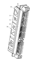
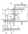
- FIG. 1 is a perspective view of the connector 10 according to the present embodiment as viewed from the rear
- FIG. 2 is a perspective view of the connector 10 as viewed from the front
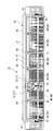
- 3 is a rear view of the connector 10
- FIG. 4 is a bottom view of the connector 10
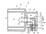
- FIG. 5 is a cross-sectional view of the connector 10
- FIG. 6 is a partial enlarged cross-sectional view of the connector 10
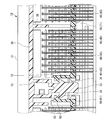
- FIG. It is a front sectional view.
- the connector 10 includes an insulating housing 20, a plurality of conductive contacts 40, and insulating tine plates 60 and 70.
- the housing 20 is positioned at a predetermined position of the substrate with its lower surface in contact with the surface of the substrate (not shown).
- the side on which the substrate is disposed is the lower side, and the opposite side is the upper side.
- the side on which the mating connector (not shown) is fitted is the front, and the side on which the tine plate 60 is arranged is the rear. This definition shall also apply to the present invention.
- the housing 20 holding the plurality of contacts 40 is integrally formed by injection molding of resin.
- the housing 20 includes a fitting portion 21 on the front side to which a mating connector (not shown) is fitted.
- a mating connector (not shown) is fitted in the fitting portion 21, three receiving spaces 24 to 26 partitioned by partition walls 22 and 23 are formed.
- the mating connector is fitted into the connector 10 by being inserted into the receiving spaces 24 to 26.
- the housing 20 includes a cover 27 on the rear side.
- the cover 27 includes an upper wall 28 and a pair of left and right side walls 29 and 30.
- a rear end portion of the contact 40 including the tine portion 45 is disposed inside the cover 27 surrounded by the upper wall 28 and the side walls 29 and 30.
- a support groove 31 is formed on the inner surface of the side wall 29 to support one end located on the outer side in the width direction of the tine plate 60 (the left end in FIG. 3).
- a support groove 32 that supports one end located on the outer side (the right end in FIG. 3) is formed.
- a support piece 33 that supports the other ends of the tine plates 60 and 70 is formed inside the cover 27 (FIG. 7).
- the support piece 33 has a rectangular shape extending downward from the upper wall 28 to a predetermined position.
- the support piece 33 has a lock claw 34 that is engaged with the lock claw 63 of the tine plate 60 on one side in the width direction, and a lock claw that is engaged with the lock claw 73 of the tine plate 70 on the other side in the width direction. 35 is formed.
- a contact holding wall 36 is formed at the boundary between the fitting portion 21 and the cover 27 (FIG. 5).
- the contact 40 is held in the housing 20 by being press-fitted into a holding hole 37 formed in the contact holding wall 36.
- a tine plate restricting body 38 that protrudes from the contact holding wall 36 toward the inside of the cover 27 is formed integrally with the housing 20.
- a plurality of tine plate regulating bodies 38 are provided at predetermined intervals along the width direction of the tine plates 60 and 70 (housing 20). The upper end of the tine plate restricting body 38 is continuous with the upper wall 28 of the cover 27, and the amount of protrusion continuously decreases from the upper end to a predetermined position toward the contact holding wall 36.
- the tine plate restricting body 38 has a constant protruding amount from the contact holding wall 36 from the predetermined position to the lower end (FIG. 5). This protrusion amount is set so that the lower end 38B of the tine plate restricting body 38 and the tine plates 60, 70 interfere in the vertical direction. Further, the amount of protrusion of the tine plate restricting body 38 is continuously reduced toward the contact holding wall 36, and the contact 40 is set around the tine plate restricting body 38 by setting the protrusion from the predetermined position to the lower end. The strength of the tine plate restricting body 38 is ensured as much as possible while securing the working space.
- the contact 40 includes a contact portion 42 that contacts the contact of the mating connector, a hanging portion 44 having a tine portion 45 inserted into the connection hole of the board at the tip, and a bent portion 46 that connects the contacting portion 42 and the hanging portion 44. (FIGS. 5 and 6).
- the contact portion 42 extends substantially parallel to the fitting direction with the mating connector, and the hanging portion 44 extends in a direction substantially orthogonal to the fitting direction.
- the contact 40 is formed by punching a thin metal plate and bending it at approximately 90 ° at the bent portion 46.
- the contact 40 is made of a highly conductive and highly elastic material such as a copper alloy.
- the plurality of contacts 40 are held in the housing 20 by being press-fitted into the contact holding wall 36. In this state, the tine portion 45 of each contact 40 is inserted into the connection hole of the substrate.
- the tine portions 45 of the contacts 40 are arranged in parallel with each other, and the tine portions 45 of all the contacts 40 are arranged so as to correspond to the connection holes of the substrate.
- the tine portion 45 is fixed to the substrate by soldering in the connection hole.
- a plurality of contacts 40 are arranged along the width direction of the housing 20, and a plurality of contacts 40 are arranged along the vertical direction of the housing 20.
- the lowermost contact 40 ⁇ / b> S with the hanging portion 44 (44 ⁇ / b> S) closest to the contact holding wall 36 has a short contact portion 42 ⁇ / b> S (hereinafter referred to as a protruding length) protruding from the back surface of the contact holding wall 36.
- the length of the drooping portion 44S to the tine plate 60 (hereinafter, drooping length) is short.
- the contact 40S has the shortest distance from the tine plate 60 to the contact portion 42S.
- the collision of the tine plate 60 occurs at the contact portion 42S of the lowermost contact 40S.
- the contact 40L having the drooping portion 44 (44L) farthest from the contact holding wall 36 has a long protruding length and a long drooping length.
- the tine plates 60 and 70 are composed of plate bodies 61 and 71 and lock arms 62 and 72 formed at one ends of the plate bodies 61 and 71.
- the lock arms 62 and 72 are provided with lock claws 63 and 73, and the tine plate 60 is positioned below the housing 20 by engaging the lock claws 63 and 73 with the lock claws 34 and 35 of the housing 20. It is supported so as not to cause displacement.
- a plurality of positioning holes 64, 74 penetrating through the upper and lower surfaces of the plate bodies 61, 71 are formed in the same arrangement as the tine portions 45 of the plurality of contacts 40.
- the positioning holes 64 and 74 are usually tapered at the upper end so that the tine portion 45 of the contact 40 can be easily inserted.
- the contacts 40 are press-fitted into the contact holding walls 36 to bring the tine portions 45 into a predetermined alignment state, and then the tine plates 60 are brought into contact with the contacts 40 from below the cover 27. Move closer. At this time, each contact 40 and the corresponding positioning hole 64 (74) are aligned. Even if the position of the tine portion 45 is deviated, the displacement can be corrected by inserting the tine portion 45 through the positioning hole 64 (74). By inserting all the tine portions 45 into the corresponding positioning holes 64 (74), it is possible to align all the tine portions 45 with the connection holes of the substrate. By assembling the tine plates 60, 70 to a predetermined position of the housing 20, the assembly of the tine plates 60, 70 to the housing 20 is completed.
- the connector 10 includes a tine plate restricting body 38.
- the tine plate restricting body 38 has a function of preventing the tine plates 60 and 70 from moving above a predetermined position and colliding with the contact portion 42S of the lowermost contact 40S.
- the lower end 38B of the tine plate restricting body 38 is positioned below the lower surface of the contact portion 42S of the lowermost contact 40S (FIGS. 5 and 6). Therefore, even if the tine plate 60 moves upward, the front end portion of the tine plate 60 interferes with the tine plate restricting body 38 and cannot move beyond the position of the lower end 38B.
- the connector 10 it is possible to prevent the tine plate 60 from colliding with the contact portion 42 ⁇ / b> S of the lowermost contact 40 ⁇ / b> S by erroneously pushing up the tine plate 60 when the tine plate 60 is assembled. Since the lower end 38B of the tine plate restricting body 38 is located below the lower surface of the contact portion 42S of the lowermost contact 40S, the tine plate restricting body 38 is connected to all the contacts 40 disposed above the lowermost contact 40S. The collision of the plate 60 is prevented.
- a taper is formed at the upper end of the positioning hole 64, and even if the upper surface of the tine plate 60 reaches the position of the bent portion 46 ⁇ / b> S, the bent portion 46 ⁇ / b> S fits in the taper, and the bent portion 46 ⁇ / b> S collides with the tine plate 60. do not do. Therefore, if the tine plate 60 having a taper formed at the upper end of the positioning hole 64 is used, the tine plate 60 can be positioned higher, which is effective in reducing the height of the connector 10.
- the position of the lower end 38B of the tine plate restricting body 38 is set to bend the lowermost contact 40S in order to prevent the tine plate 60 and the bent portion 46S from colliding with each other. It is preferable to be lower than the portion 46S.
- the position of the lower end 38B may be applied to the tine plate 60 in which the upper end of the positioning hole 64 is tapered.
- the connector 10 has a tine plate restricting body 38 formed integrally with the housing 20 by injection molding. Therefore, it is not necessary to produce a tine plate restricting body as a separate member, and it is not necessary to install the tine plate restricting body at a predetermined position. Therefore, the connector 10 has a contact portion 42S of the lowermost contact 40S with almost no increase in manufacturing cost. Thus, the tine plate 60 can be prevented from colliding. However, the present invention does not exclude producing the tine plate restricting body 38 as a separate member from the housing 20.
- the connector 10 is provided with four tine plate restricting bodies 38 at the intermediate portion except for both ends in the width direction of the housing 20, but the present invention does not necessarily require providing a plurality of tine plate restricting bodies 38.
- the present invention can prevent the tine plate 60 from colliding with the lowermost contact 40 ⁇ / b> S by providing at least one tine plate restricting body 38 in the intermediate portion of the housing 20. Therefore, the number of tine plate restrictors 38 should be determined as appropriate mainly in accordance with the dimensions of the tine plate 60 and other situations.
- the form of the tine plate regulating body 38 is not limited as long as the tine plate 60 has a function of preventing the tine plate 60 from moving above a predetermined position and colliding with the contact portion 42S of the lowermost contact 40S.
- the connector 10 includes two tine plates 60 and 70, the present invention can be applied to a connector including one tine plate.
- the contact to which the present invention is applied is not limited to the contact 40.
- the contact 40 is bent at 90 ° by the bent portion 46, but the tine plate 60 (70) collides with the contact portion 42 by the tine plate restricting body 38 even if the bending angle is an obtuse or acute angle. Can be prevented.
- the contact 40 is a male contact, but the present invention can also be applied to a female contact.
- the contact portion 42 is not limited to a straight one, and the present invention can also be applied to a curved portion according to the shape of the counterpart contact.
- the connector 10 has a plurality of contacts 40 arranged along the vertical direction of the housing 20, the present invention is not limited to this. Even in the case where the contacts 40 are arranged in a single row in the vertical direction of the housing 20, the tine plate regulating body 38 can be provided to prevent the tine plate 60 (70) from colliding with the contact portion 42. In addition to this, as long as it does not depart from the gist of the present invention, the configuration described in the above embodiment can be selected or changed to another configuration as appropriate.
Landscapes
- Coupling Device And Connection With Printed Circuit (AREA)
Abstract
タインプレート付きのコネクタを低背化しても、タインプレートがコンタクトに衝突するのを防止できるコネクタを提供する。 本発明は、タインプレート(60)から接触部(42)までの上下方向の距離が最も短い最下段コンタクト(40S)を含むコネクタ(10)において、タインプレート(60)の上への移動を妨げるタインプレート規制体(38)が、ハウジングと一体に形成されている。タインプレート規制体(38)は、最下段コンタクト(40S)の接触部(42S)よりも下において、タインプレート(60)と干渉することにより、タインプレート(60)の上への移動を規制する。
Description
本発明は、回路基板に実装される電気コネクタに関するものであり、特にタインプレートによりコンタクトのタイン部を整列させる電気コネクタに関するものである。
従来から、プリント配線基板等の回路基板(以下、単に基板という)に実装され、基板と他の電気回路とを接続する電気コネクタ(以下、単にコネクタという)が広く使われている。このコネクタは、コンタクトと、このコンタクトを保持するハウジングとを主たる構成要素としている。このコンタクトは、基板に形成される接続用の貫通孔に挿入されるタイン部と、互いに嵌合する相手コネクタのコンタクトに接触する接触部とを備えている。コンタクトは、通常、薄い金属板を打ち抜くと共に折り曲げて形成されるものであり、タイン部はハウジングの背面から後方に突出している。このため、コネクタを輸送する最中、あるいは取り扱い中にタイン部が力を受けて位置ずれを起こすおそれがある。タイン部に位置ずれが生ずると、タイン部を基板の貫通孔に正確に挿入することができなくなる。
そこで、タイン部を整列させ、かつ位置ずれを防ぐために、タインプレートが用いられている。タインプレートには、タインプレートを貫通する位置決め孔が形成されており、この位置決め孔にタイン部を貫通させる。そうすることにより、タイン部を基板の接続孔に対して正確に位置決めし、かつ位置ずれを防ぐことができる。
そこで、タイン部を整列させ、かつ位置ずれを防ぐために、タインプレートが用いられている。タインプレートには、タインプレートを貫通する位置決め孔が形成されており、この位置決め孔にタイン部を貫通させる。そうすることにより、タイン部を基板の接続孔に対して正確に位置決めし、かつ位置ずれを防ぐことができる。
図8を参照して、従来のタインプレート付きコネクタ100について説明する。
コンタクト130は、相手コネクタのコンタクトに接触する接触部を含む平行部132を有している。コンタクト130は、ハウジング120の背面から所定長だけ突出した位置でおよそ90°だけ屈曲し、かつ下方へ垂下する垂下部134を有している。垂下部134の先端部分がタイン部135を構成し、このタイン部135が基板Pの接続孔Hと対応するように、コンタクト130は配列されている。コネクタ100を基板Pに取り付ける際には、基板Pの所定位置にハウジング120を配置すると共に、各タイン部135を接続孔Hに挿入してはんだ付け部Mにより固着する。また、ハウジング120には、コンタクト130の接続孔Hへの挿入動作を容易にするための手段としてタインプレート140が使用されている。タインプレート140には、基板Pの接続孔Hに対応する位置決め孔141が形成されており、コンタクト130のタイン部135を各位置決め孔141に貫通させることによってコンタクト130相互間の位置関係が接続孔Hの配列と一致するように整列される。
コンタクト130は、相手コネクタのコンタクトに接触する接触部を含む平行部132を有している。コンタクト130は、ハウジング120の背面から所定長だけ突出した位置でおよそ90°だけ屈曲し、かつ下方へ垂下する垂下部134を有している。垂下部134の先端部分がタイン部135を構成し、このタイン部135が基板Pの接続孔Hと対応するように、コンタクト130は配列されている。コネクタ100を基板Pに取り付ける際には、基板Pの所定位置にハウジング120を配置すると共に、各タイン部135を接続孔Hに挿入してはんだ付け部Mにより固着する。また、ハウジング120には、コンタクト130の接続孔Hへの挿入動作を容易にするための手段としてタインプレート140が使用されている。タインプレート140には、基板Pの接続孔Hに対応する位置決め孔141が形成されており、コンタクト130のタイン部135を各位置決め孔141に貫通させることによってコンタクト130相互間の位置関係が接続孔Hの配列と一致するように整列される。
一般に、基板もタインプレートも共に樹脂製であるが、材質の異なる樹脂で製造されているため、両者の熱膨張率は互いに異なる。従って、タイン部を基板にはんだ付けするために加熱処理を行うと、両者の熱膨張差に起因して、コンタクトが基板に固定された部分と、タインプレートの貫通孔に位置する部分とに互いに異なる向きの外力が作用し、この外力がタイン部のはんだ付け強度を超えるとはんだ付け部に割れが発生するおそれがある。
このような問題に対して、タイン部の挿入時には高い位置精度が維持され、かつはんだ付け時においては応力の緩和を図ることのできるタインプレート付きのコネクタが特許文献1に開示されている。
このような問題に対して、タイン部の挿入時には高い位置精度が維持され、かつはんだ付け時においては応力の緩和を図ることのできるタインプレート付きのコネクタが特許文献1に開示されている。
例えば自動車に搭載されるコネクタは、車室内に搭載されるといった理由から、小型化、特に低背化されることが望まれることがある。コネクタを低背化するには、ハウジング120の最も下側に配置される最下段コンタクト130Sとタインプレート140との上下方向の距離を短くする必要がある(図8)。そのために、以下の課題が生じる場合がある。
タインプレート140を組み付ける際に、タインプレート140を押し上げすぎると、タインプレート140が最下段コンタクト130Sの平行部132Sに衝突してしまう。そうすると、最下段コンタクト130Sのタイン部135Sに位置ずれが生じ、基板Pの接続孔Hにタイン部135を挿入できなくなる場合がある。
また、例えば自動車にコネクタ100を搭載した後には、自動車の運転に伴う振動によって、タインプレート140が上に移動し又は上を凸にする変形(以下、両者を含めて移動と略記する)が生じると、タインプレート140が最下段コンタクト130Sの平行部132Sに衝突することがある。そうすると、最下段コンタクト130Sに外力が加わるが、この外力がはんだ付け部Mの強度を超えると、はんだ付け部Mが割れるおそれがある。はんだ付け部Mが割れると、最下段コンタクト130Sのタイン部135Sと基板Pとの電気的接続の信頼性が低下する場合がある。
タインプレート140を組み付ける際に、タインプレート140を押し上げすぎると、タインプレート140が最下段コンタクト130Sの平行部132Sに衝突してしまう。そうすると、最下段コンタクト130Sのタイン部135Sに位置ずれが生じ、基板Pの接続孔Hにタイン部135を挿入できなくなる場合がある。
また、例えば自動車にコネクタ100を搭載した後には、自動車の運転に伴う振動によって、タインプレート140が上に移動し又は上を凸にする変形(以下、両者を含めて移動と略記する)が生じると、タインプレート140が最下段コンタクト130Sの平行部132Sに衝突することがある。そうすると、最下段コンタクト130Sに外力が加わるが、この外力がはんだ付け部Mの強度を超えると、はんだ付け部Mが割れるおそれがある。はんだ付け部Mが割れると、最下段コンタクト130Sのタイン部135Sと基板Pとの電気的接続の信頼性が低下する場合がある。
本発明は、このような技術的課題に基づいてなされたもので、タインプレートがコンタクトに衝突するのを防ぐことのできるコネクタを提供することを目的とする。
本発明のコネクタは、複数のコンタクトと、ハウジングと、タインプレートとから構成される。各コンタクトは、互いに嵌合される相手コネクタのコンタクトに接触する接触部と、回路基板に形成される接続孔に挿入されるタイン部を含む垂下部と、接触部と垂下部とを繋ぐ屈曲部とを備えている。ハウジングは、複数のコンタクトを保持する。タインプレートは、複数のコンタクトの垂下部が貫通する複数の位置決め孔が形成され、対応する垂下部を位置決め孔に貫通させることにより複数のタイン部を所定位置に整列させる。
以上の基本的な構成を有する本発明のコネクタは、タインプレートの上への移動を妨げるタインプレート規制体が備えられており、このタインプレート規制体は、接触部よりも下でタインプレートの上への移動を規制することを特徴としている。
本発明のコネクタは、タインプレート規制体が、コンタクトの接触部よりも下でタインプレートの上への移動を規制するので、タインプレートが、最下段コンタクトの接触部に衝突するのを防ぐことができる。
以上の基本的な構成を有する本発明のコネクタは、タインプレートの上への移動を妨げるタインプレート規制体が備えられており、このタインプレート規制体は、接触部よりも下でタインプレートの上への移動を規制することを特徴としている。
本発明のコネクタは、タインプレート規制体が、コンタクトの接触部よりも下でタインプレートの上への移動を規制するので、タインプレートが、最下段コンタクトの接触部に衝突するのを防ぐことができる。
本発明のコネクタは、複数のコンタクトがハウジングの上下方向に1列だけ配列される場合に加え、複数のコンタクトがハウジングの上下方向に複数配列される場合の両者に適用できる。後者の場合、タインプレートから屈曲部までの上下方向の距離が最も短い最下段コンタクトが少なくとも含まれる。この形態において、タインプレート規制体は、最下段コンタクトの接触部よりも下で、タインプレートの上への移動を規制することが好ましい。複数のコンタクトがハウジングの上下方向に複数配列される場合、前述したように、最下段コンタクトにタインプレートが衝突するおそれがあるからである。
また、本発明のコネクタにおいて、タインプレート規制体をハウジングと一体に形成することが好ましい。そうすると、ハウジングとは別部材としてタインプレート規制体を作製し、所定位置に設置する必要がないので、製作コストの上昇をほとんど招くことがない。もっとも、本発明は、ハウジングとは別部材としてタインプレート規制体を作製し、所定位置に設置する形態を排除するものでない。
本発明のコネクタにおいて、ハウジングの上下方向に所定長を有し、かつハウジングの前後方向に突出するタインプレート規制体の場合、ハウジングの上に比べて下の突出の量が少ないことが好ましい。そうすることにより、タインプレート規制体の周囲のコンタクトの設置の邪魔にならないように作業空間を確保することができる。
本発明のコネクタにおいて、タインプレート規制体は、最下段コンタクトの屈曲部よりも下で、タインプレートの上への移動を規制することが好ましい。一般に、タインプレートの位置決め孔の上部はテーパ状となっている。そのため、平行部よりも下でタインプレートの上への移動を規制すれば、平行部へのタインプレートの接触を防ぐことができる。ただし、平行部へのタインプレートの接触をより確実に防ぎ、またはタインプレートの位置決め孔の上部にテーパが形成されていないかあるいは形成されていても小さい場合に、最下段コンタクトの屈曲部よりも下において、タインプレートの上への移動を規制することが有効である。
タインプレート規制体は、一つのタインプレートに対して少なくとも一つ形成すれば、その効果を得ることができる。しかし、タインプレートの幅方向の長さが長い場合には、複数のタインプレート規制体を、その幅方向に沿って設けることにより、接触部へのタインプレートの接触をより確実に防ぐことができる。
本発明によれば、タインプレートがコンタクトに衝突するのを防ぐことのできるコネクタが提供される。
以下、添付図面に示す実施の形態に基づいてこの発明を詳細に説明する。
図1は本実施の形態におけるコネクタ10を後方から視た斜視図、図2はコネクタ10を前方から視た斜視図である。また、図3はコネクタ10の背面図、図4はコネクタ10の底面図、図5はコネクタ10の横断面図、図6はコネクタ10の部分拡大横断面図、図7はコネクタ10の部分拡大正断面図である。
コネクタ10は、絶縁性のハウジング20と、複数の導電性のコンタクト40と、絶縁性のタインプレート60、70とを備えている。ハウジング20は、その下面が基板(図示せず)の表面に接触した状態で、基板の所定位置に位置決めされる。なお、ハウジング20において、基板が配置される側を下、その反対側を上とする。また、ハウジング20において、相手コネクタ(図示せず)が嵌合される側を前、タインプレート60が配置される側を後とする。この定義は、本願発明にも適用されるものとする。
図1は本実施の形態におけるコネクタ10を後方から視た斜視図、図2はコネクタ10を前方から視た斜視図である。また、図3はコネクタ10の背面図、図4はコネクタ10の底面図、図5はコネクタ10の横断面図、図6はコネクタ10の部分拡大横断面図、図7はコネクタ10の部分拡大正断面図である。
コネクタ10は、絶縁性のハウジング20と、複数の導電性のコンタクト40と、絶縁性のタインプレート60、70とを備えている。ハウジング20は、その下面が基板(図示せず)の表面に接触した状態で、基板の所定位置に位置決めされる。なお、ハウジング20において、基板が配置される側を下、その反対側を上とする。また、ハウジング20において、相手コネクタ(図示せず)が嵌合される側を前、タインプレート60が配置される側を後とする。この定義は、本願発明にも適用されるものとする。
<ハウジング20>
複数のコンタクト40を保持するハウジング20は、樹脂を射出成形することにより、一体に形成される。
ハウジング20は、図示しない相手コネクタが嵌合される嵌合部21を前側に備えている。嵌合部21には、仕切り壁22、23により仕切られた3つの受容空間24~26が形成されている。相手コネクタは、この受容空間24~26に挿入されることにより、コネクタ10と嵌合される。
複数のコンタクト40を保持するハウジング20は、樹脂を射出成形することにより、一体に形成される。
ハウジング20は、図示しない相手コネクタが嵌合される嵌合部21を前側に備えている。嵌合部21には、仕切り壁22、23により仕切られた3つの受容空間24~26が形成されている。相手コネクタは、この受容空間24~26に挿入されることにより、コネクタ10と嵌合される。
ハウジング20は、カバー27を後側に備えている。カバー27は、上壁28と、左右一対の側壁29、30とから構成される。上壁28と側壁29、30とで囲まれたカバー27の内部に、タイン部45を含むコンタクト40の後端部が配置される。
側壁29の内面には、タインプレート60の幅方向の外側(図3 左端)に位置する一端を支持する支持溝31が形成され、また、側壁30の内面には、タインプレート70の幅方向の外側(図3 右端)に位置する一端を支持する支持溝32が形成されている。
カバー27の内部には、タインプレート60、70の他端を支持する支持片33が形成されている(図7)。支持片33は、上壁28から下方に向けて所定の位置まで延びる矩形状の形状をなしている。支持片33は、幅方向の一方側にタインプレート60のロック爪63と係止されるロック爪34が、また、幅方向の他方側にタインプレート70のロック爪73と係止されるロック爪35が形成されている。
側壁29の内面には、タインプレート60の幅方向の外側(図3 左端)に位置する一端を支持する支持溝31が形成され、また、側壁30の内面には、タインプレート70の幅方向の外側(図3 右端)に位置する一端を支持する支持溝32が形成されている。
カバー27の内部には、タインプレート60、70の他端を支持する支持片33が形成されている(図7)。支持片33は、上壁28から下方に向けて所定の位置まで延びる矩形状の形状をなしている。支持片33は、幅方向の一方側にタインプレート60のロック爪63と係止されるロック爪34が、また、幅方向の他方側にタインプレート70のロック爪73と係止されるロック爪35が形成されている。
嵌合部21とカバー27との境界には、コンタクト保持壁36が形成されている(図5)。コンタクト40は、コンタクト保持壁36に形成される保持孔37に圧入されることにより、ハウジング20に保持される。
コンタクト保持壁36からカバー27の内部に向けて突出するタインプレート規制体38が、ハウジング20に一体に形成されている。タインプレート規制体38は、タインプレート60、70(ハウジング20)の幅方向に沿って所定の間隔を隔てて複数設けられている。タインプレート規制体38は、その上端がカバー27の上壁28と連なり、上端から所定の位置まで、コンタクト保持壁36に向かって、連続的に突出量が減少する。タインプレート規制体38は、この所定位置から下端までは、コンタクト保持壁36からの突出量が一定とされている(図5)。この突出量は、タインプレート規制体38の下端38Bとタインプレート60、70とが、上下方向において干渉するように設定されている。また、タインプレート規制体38の突出量を、コンタクト保持壁36に向かって連続的に減少し、所定位置から下端までは少なく設定することにより、タインプレート規制体38の周囲にコンタクト40を設置する際の作業空間を確保しつつ、できるだけタインプレート規制体38の強度も確保している。
コンタクト保持壁36からカバー27の内部に向けて突出するタインプレート規制体38が、ハウジング20に一体に形成されている。タインプレート規制体38は、タインプレート60、70(ハウジング20)の幅方向に沿って所定の間隔を隔てて複数設けられている。タインプレート規制体38は、その上端がカバー27の上壁28と連なり、上端から所定の位置まで、コンタクト保持壁36に向かって、連続的に突出量が減少する。タインプレート規制体38は、この所定位置から下端までは、コンタクト保持壁36からの突出量が一定とされている(図5)。この突出量は、タインプレート規制体38の下端38Bとタインプレート60、70とが、上下方向において干渉するように設定されている。また、タインプレート規制体38の突出量を、コンタクト保持壁36に向かって連続的に減少し、所定位置から下端までは少なく設定することにより、タインプレート規制体38の周囲にコンタクト40を設置する際の作業空間を確保しつつ、できるだけタインプレート規制体38の強度も確保している。
<コンタクト40>
コンタクト40は、相手コネクタのコンタクトに接触する接触部42と、基板の接続孔に挿入されるタイン部45を先端に有する垂下部44と、接触部42と垂下部44とを繋ぐ屈曲部46とを有している(図5、図6)。コンタクト40は、接触部42が相手コネクタとの嵌合方向と略平行に延びており、垂下部44は当該嵌合方向と略直交する方向に延びている。コンタクト40は、薄い金属板を打ち抜くと共に、屈曲部46においておよそ90°に折り曲げて形成されるものである。コンタクト40は、例えば銅合金のような高導電性かつ高弾性の材料から構成される。
コンタクト40は、相手コネクタのコンタクトに接触する接触部42と、基板の接続孔に挿入されるタイン部45を先端に有する垂下部44と、接触部42と垂下部44とを繋ぐ屈曲部46とを有している(図5、図6)。コンタクト40は、接触部42が相手コネクタとの嵌合方向と略平行に延びており、垂下部44は当該嵌合方向と略直交する方向に延びている。コンタクト40は、薄い金属板を打ち抜くと共に、屈曲部46においておよそ90°に折り曲げて形成されるものである。コンタクト40は、例えば銅合金のような高導電性かつ高弾性の材料から構成される。
複数のコンタクト40は、コンタクト保持壁36に圧入されることにより、ハウジング20に保持される。この状態で、各コンタクト40のタイン部45は、基板の接続孔に挿入される。各コンタクト40のタイン部45は、互いに平行に配列されており、且つ全てのコンタクト40のタイン部45は、基板の接続孔と対応するように配列されている。タイン部45は、接続孔においてはんだ付けにより基板に固着される。
コンタクト40は、ハウジング20の幅方向に沿って複数配列され、また、ハウジング20の上下方向に沿って複数配列されている。ハウジング20の上下方向において、垂下部44(44S)がコンタクト保持壁36から最も近い最下段コンタクト40Sは、コンタクト保持壁36の背面から突出する接触部42Sの長さ(以下、突出長)が短く、かつタインプレート60までの垂下部44Sの長さ(以下、垂下長)が短い。このコンタクト40Sは、タインプレート60から接触部42Sまでの距離が最も短い。タインプレート60の衝突は、この最下段コンタクト40Sの接触部42Sに生ずる。逆に、上下方向において、垂下部44(44L)がコンタクト保持壁36から最も遠いコンタクト40Lは、突出長が長く、かつ垂下長が長い。
<タインプレート60、70>
次に、タインプレート60、70について説明する。
タインプレート60、70は、プレート本体61、71と、プレート本体61、71の一端に形成されるロックアーム62、72とから構成される。ロックアーム62、72にはロック爪63、73が設けてあり、このロック爪63、73とハウジング20のロック爪34、35とを係止させることによって、タインプレート60がハウジング20の下に位置ずれを起こさないように支持される。
プレート本体61、71には、その上下両面に貫通する複数の位置決め孔64、74が、複数のコンタクト40のタイン部45と同じ配列で形成されている。位置決め孔64、74には、通常、コンタクト40のタイン部45を挿入しやすいように、上端にテーパが形成される。
次に、タインプレート60、70について説明する。
タインプレート60、70は、プレート本体61、71と、プレート本体61、71の一端に形成されるロックアーム62、72とから構成される。ロックアーム62、72にはロック爪63、73が設けてあり、このロック爪63、73とハウジング20のロック爪34、35とを係止させることによって、タインプレート60がハウジング20の下に位置ずれを起こさないように支持される。
プレート本体61、71には、その上下両面に貫通する複数の位置決め孔64、74が、複数のコンタクト40のタイン部45と同じ配列で形成されている。位置決め孔64、74には、通常、コンタクト40のタイン部45を挿入しやすいように、上端にテーパが形成される。
タインプレート60、70をハウジング20に組み付ける際には、コンタクト40をコンタクト保持壁36に圧入して、タイン部45を所定の整列状態とした後に、タインプレート60をカバー27の下方からコンタクト40に接近させる。このとき、各コンタクト40と対応する位置決め孔64(74)とを位置合わせする。仮に、タイン部45の位置がずれていても、位置決め孔64(74)に当該タイン部45を挿通することにより、位置ずれを矯正することができる。全てのタイン部45を対応する位置決め孔64(74)に挿通することにより、全てのタイン部45と基板の接続孔との位置合わせを行うことができる。タインプレート60、70を、ハウジング20の所定位置まで押し込むことにより、ハウジング20に対するタインプレート60、70の組み付けは完了する。
以上の構成を有するコネクタ10の特徴部分について、以下説明する。
コネクタ10は、タインプレート規制体38を備えている。このタインプレート規制体38は、タインプレート60、70が、所定の位置よりも上に移動して、最下段コンタクト40Sの接触部42Sと衝突するのを防ぐ機能を有している。
以上の機能を果たすために、タインプレート規制体38は、その下端38Bが、最下段コンタクト40Sの接触部42Sの下面よりも下に位置している(図5、図6)。したがって、タインプレート60が上に移動しようとしても、タインプレート60の前端部分がタインプレート規制体38に干渉して、下端38Bの位置を越えて移動することができない。したがって、コネクタ10によれば、タインプレート60の組み付け時に、誤ってタインプレート60を押し上げすぎて、最下段コンタクト40Sの接触部42Sにタインプレート60が衝突するのを防ぐことができる。タインプレート規制体38は、その下端38Bが、最下段コンタクト40Sの接触部42Sの下面よりも下に位置しているので、最下段コンタクト40Sよりも上に配置される全てのコンタクト40へのタインプレート60の衝突を防ぐことになる。
コネクタ10は、タインプレート規制体38を備えている。このタインプレート規制体38は、タインプレート60、70が、所定の位置よりも上に移動して、最下段コンタクト40Sの接触部42Sと衝突するのを防ぐ機能を有している。
以上の機能を果たすために、タインプレート規制体38は、その下端38Bが、最下段コンタクト40Sの接触部42Sの下面よりも下に位置している(図5、図6)。したがって、タインプレート60が上に移動しようとしても、タインプレート60の前端部分がタインプレート規制体38に干渉して、下端38Bの位置を越えて移動することができない。したがって、コネクタ10によれば、タインプレート60の組み付け時に、誤ってタインプレート60を押し上げすぎて、最下段コンタクト40Sの接触部42Sにタインプレート60が衝突するのを防ぐことができる。タインプレート規制体38は、その下端38Bが、最下段コンタクト40Sの接触部42Sの下面よりも下に位置しているので、最下段コンタクト40Sよりも上に配置される全てのコンタクト40へのタインプレート60の衝突を防ぐことになる。
コネクタ10は、位置決め孔64の上端にテーパが形成され、タインプレート60の上面が屈曲部46Sの位置に達しても、屈曲部46Sはテーパ内に収まるので、屈曲部46Sがタインプレート60と衝突しない。したがって、位置決め孔64の上端にテーパを形成したタインプレート60を用いれば、タインプレート60をより上に位置させることができるので、コネクタ10の低背化に有効である。
一方で、テーパが形成されていないタインプレート60を用いる場合には、タインプレート60と屈曲部46Sとの衝突を防ぐために、タインプレート規制体38の下端38Bの位置を、最下段コンタクト40Sの屈曲部46Sよりも下にすることが好ましい。もちろん、この下端38Bの位置は、位置決め孔64の上端にテーパを形成したタインプレート60に適用してもよいことは言うまでもない。
コネクタ10は、タインプレート規制体38を、射出成形によりハウジング20と一体に形成している。したがって、別部材としてタインプレート規制体を作製する必要がなく、かつ所定位置に設置する作業を要しないので、コネクタ10は、製作コストの上昇をほとんど招くことなく、最下段コンタクト40Sの接触部42Sにタインプレート60が衝突するのを防ぐことができる。ただし、本発明は、タインプレート規制体38を、ハウジング20とは別部材として作製することを排除しない。
コネクタ10は、タインプレート規制体38を、ハウジング20の幅方向の両端を除く中間部分に4つ設けたが、本発明は、複数のタインプレート規制体38を設けることを必須としない。本発明は、ハウジング20の中間部に少なくとも1つのタインプレート規制体38を設けることにより、タインプレート60が最下段コンタクト40Sに衝突するのを防ぐことができる。したがって、タインプレート規制体38の数は、主にタインプレート60の寸法、その他の状況に応じて適宜定めるべきである。もちろん、複数のタインプレート60を設けることにより、タインプレート60が最下段コンタクト40Sに衝突するのを防ぐ効果をより確実に得られることは言うまでもない。
また、タインプレート60が、所定の位置よりも上に移動して、最下段コンタクト40Sの接触部42Sと衝突するのを防ぐ機能を有していれば、タインプレート規制体38の形態を問わない。
コネクタ10は、2つのタインプレート60、70を備えているが、1つのタインプレートを備えたコネクタに本発明を適用できる。
コネクタ10は、2つのタインプレート60、70を備えているが、1つのタインプレートを備えたコネクタに本発明を適用できる。
本発明が適用されるコンタクトはコンタクト40に限らない。コンタクト40は、屈曲部46で90°に折り曲げられているが、この折り曲げの角度は鈍角または鋭角であっても、タインプレート規制体38によりタインプレート60(70)が接触部42に衝突するのを防ぐことができる。また、コンタクト40は、おす型のコンタクトであるが、めす型のコンタクトについても本発明を適用とすることができる。さらに、接触部42は、真直ぐなものに限定されず、相手側のコンタクトの形状に応じて、湾曲しているものについても、本発明を適用することができる。
コネクタ10は、ハウジング20の上下方向に沿ってコンタクト40が複数配列されているが、本発明はこれに限定されない。ハウジング20の上下方向にコンタクト40が1列だけ配列されるものにも、タインプレート規制体38を設けることにより、タインプレート60(70)が接触部42に衝突するのを防ぐことができる。
これ以外にも、本発明の主旨を逸脱しない限り、上記実施の形態で挙げた構成を取捨選択したり、他の構成に適宜変更することが可能である。
これ以外にも、本発明の主旨を逸脱しない限り、上記実施の形態で挙げた構成を取捨選択したり、他の構成に適宜変更することが可能である。
10…コネクタ
20…ハウジング
21…嵌合部、22,23…仕切り壁、24~26…受容空間、27…カバー、28…上壁、
29,30…側壁、31,32…支持溝、33…支持片、34,35…ロック爪
36…コンタクト保持壁、37…保持孔、38…タインプレート規制体
40…コンタクト,40S…最下段コンタクト
42,42S…接触部、44,44S…垂下部、45,45S…タイン部、
46,46S…屈曲部
60,70…タインプレート
61,71…プレート本体、62,72…ロックアーム、63,73…ロック爪
64,74…位置決め孔
20…ハウジング
21…嵌合部、22,23…仕切り壁、24~26…受容空間、27…カバー、28…上壁、
29,30…側壁、31,32…支持溝、33…支持片、34,35…ロック爪
36…コンタクト保持壁、37…保持孔、38…タインプレート規制体
40…コンタクト,40S…最下段コンタクト
42,42S…接触部、44,44S…垂下部、45,45S…タイン部、
46,46S…屈曲部
60,70…タインプレート
61,71…プレート本体、62,72…ロックアーム、63,73…ロック爪
64,74…位置決め孔
Claims (7)
- 互いに嵌合される相手コネクタのコンタクトに接触する接触部と、回路基板に形成される接続孔に挿入されるタイン部を含む垂下部と、前記接触部と前記垂下部とを繋ぐ屈曲部とをそれぞれが有する複数のコンタクトと、
複数の前記コンタクトが保持されるハウジングと、
複数の前記コンタクトの前記垂下部が貫通する複数の位置決め孔が形成され、対応する前記垂下部を前記位置決め孔に貫通させることにより複数の前記タイン部を所定位置に整列させるタインプレートと、を備える電気コネクタであって、
前記タインプレートの上への移動を妨げるタインプレート規制体が備えられ、
前記タインプレート規制体は、前記接触部よりも下で、前記タインプレートの上への移動を規制することを特徴とする電気コネクタ。 - 複数の前記コンタクトは、前記ハウジングの上下方向に複数配列され、前記タインプレートから前記屈曲部までの前記上下方向の距離が最も短い最下段コンタクトを少なくとも含み、
前記タインプレート規制体は、前記最下段コンタクトの前記接触部よりも下で、前記タインプレートの上への移動を規制することを特徴とする請求項1に記載の電気コネクタ。 - 前記タインプレート規制体は、前記ハウジングと一体に形成されることを特徴とする請求項1に記載の電気コネクタ。
- 前記ハウジングの上下方向に所定長を有し、かつ前記ハウジングの前後方向に突出する前記タインプレート規制体は、前記ハウジングの上に比べて下の前記突出の量が少ないことを特徴とする請求項1に記載の電気コネクタ。
- 前記タインプレート規制体は、前記屈曲部よりも下で、前記タインプレートの上への移動を規制することを特徴とする請求項1に記載の電気コネクタ。
- 複数の前記コンタクトは、前記ハウジングの上下方向に複数配列され、前記タインプレートから前記屈曲部までの前記上下方向の距離が最も短い最下段コンタクトを少なくとも含み、
前記タインプレート規制体は、前記最下段コンタクトの前記屈曲部よりも下で、前記タインプレートの上への移動を規制することを特徴とする請求項1に記載の電気コネクタ。 - 複数の前記タインプレート規制体が、前記タインプレートの幅方向に沿って設けられることを特徴とする請求項1に記載の電気コネクタ。
Applications Claiming Priority (2)
| Application Number | Priority Date | Filing Date | Title |
|---|---|---|---|
| JP2008-280513 | 2008-10-30 | ||
| JP2008280513A JP2010108789A (ja) | 2008-10-30 | 2008-10-30 | 電気コネクタ |
Publications (1)
| Publication Number | Publication Date |
|---|---|
| WO2010050147A1 true WO2010050147A1 (ja) | 2010-05-06 |
Family
ID=42128519
Family Applications (1)
| Application Number | Title | Priority Date | Filing Date |
|---|---|---|---|
| PCT/JP2009/005494 Ceased WO2010050147A1 (ja) | 2008-10-30 | 2009-10-20 | 電気コネクタ |
Country Status (2)
| Country | Link |
|---|---|
| JP (1) | JP2010108789A (ja) |
| WO (1) | WO2010050147A1 (ja) |
Citations (8)
| Publication number | Priority date | Publication date | Assignee | Title |
|---|---|---|---|---|
| JPS6098280U (ja) * | 1983-12-13 | 1985-07-04 | 本多通信工業株式会社 | コネクタのコンタクトの端子整列用絶縁体 |
| JPH1041026A (ja) * | 1996-07-22 | 1998-02-13 | Sumitomo Wiring Syst Ltd | 基板用コネクタ |
| JPH11176533A (ja) * | 1997-12-11 | 1999-07-02 | Sumitomo Wiring Syst Ltd | アライメントプレートおよび該アライメントプレートを備えた基板用コネクタ |
| JPH11307201A (ja) * | 1998-04-16 | 1999-11-05 | Amp Japan Ltd | 電気コネクタ |
| JP2004355983A (ja) * | 2003-05-29 | 2004-12-16 | Yamaichi Electronics Co Ltd | Icソケット |
| JP2005123120A (ja) * | 2003-10-20 | 2005-05-12 | Sumitomo Wiring Syst Ltd | 基板用コネクタ |
| JP2006309972A (ja) * | 2005-04-26 | 2006-11-09 | Molex Inc | 基板用コネクタ |
| JP2008226571A (ja) * | 2007-03-12 | 2008-09-25 | Tyco Electronics Amp Kk | アライメントプレートおよび電気コネクタ |
-
2008
- 2008-10-30 JP JP2008280513A patent/JP2010108789A/ja active Pending
-
2009
- 2009-10-20 WO PCT/JP2009/005494 patent/WO2010050147A1/ja not_active Ceased
Patent Citations (8)
| Publication number | Priority date | Publication date | Assignee | Title |
|---|---|---|---|---|
| JPS6098280U (ja) * | 1983-12-13 | 1985-07-04 | 本多通信工業株式会社 | コネクタのコンタクトの端子整列用絶縁体 |
| JPH1041026A (ja) * | 1996-07-22 | 1998-02-13 | Sumitomo Wiring Syst Ltd | 基板用コネクタ |
| JPH11176533A (ja) * | 1997-12-11 | 1999-07-02 | Sumitomo Wiring Syst Ltd | アライメントプレートおよび該アライメントプレートを備えた基板用コネクタ |
| JPH11307201A (ja) * | 1998-04-16 | 1999-11-05 | Amp Japan Ltd | 電気コネクタ |
| JP2004355983A (ja) * | 2003-05-29 | 2004-12-16 | Yamaichi Electronics Co Ltd | Icソケット |
| JP2005123120A (ja) * | 2003-10-20 | 2005-05-12 | Sumitomo Wiring Syst Ltd | 基板用コネクタ |
| JP2006309972A (ja) * | 2005-04-26 | 2006-11-09 | Molex Inc | 基板用コネクタ |
| JP2008226571A (ja) * | 2007-03-12 | 2008-09-25 | Tyco Electronics Amp Kk | アライメントプレートおよび電気コネクタ |
Also Published As
| Publication number | Publication date |
|---|---|
| JP2010108789A (ja) | 2010-05-13 |
Similar Documents
| Publication | Publication Date | Title |
|---|---|---|
| JP6663565B2 (ja) | 基板用コネクタ | |
| EP2685566B1 (en) | Electrical terminal pin | |
| JP5941515B2 (ja) | コネクタ | |
| JP5912632B2 (ja) | コネクタ | |
| EP1851826B1 (en) | Surface mount header assembly having a planar alignment surface | |
| JP2006127974A (ja) | 表面実装型電気コネクタ | |
| US11605913B2 (en) | Connector and manufacturing method of connector | |
| JP5587807B2 (ja) | フローティング型コネクタ | |
| JP4626680B2 (ja) | 保持部材、電子部品、及び電子装置 | |
| JP2007535102A (ja) | プリント配線板との無はんだの電気的な接続のためのピン、圧入工具ならびに無はんだの電気的な接続を形成するための方法 | |
| JP7283971B2 (ja) | 基板用コネクタ、及び基板用コネクタ構造 | |
| EP2073318A1 (en) | Terminal fitting insertion guide structure and electrical connector | |
| KR20230095810A (ko) | 커넥터 및 커넥터 조립체 | |
| WO2010050147A1 (ja) | 電気コネクタ | |
| CN100514756C (zh) | 表面安装底座组件 | |
| JP7082500B2 (ja) | 端子、コネクタ、及び、コネクタ装置 | |
| EP1850421B1 (en) | Reinforcing tab, method of manufacturing the same and structure of connecting connector using the same | |
| WO2015159964A1 (ja) | コネクタ | |
| WO2013137405A1 (ja) | 接続端子およびこれを用いたコネクタ | |
| JP2012243562A (ja) | コネクタ端子及びこのコネクタ端子を含むカードエッジ型コネクタ | |
| JP5511338B2 (ja) | 基板取付体 | |
| JP2007242473A (ja) | 多極コネクタおよび多極コネクタの製造方法、実装方法 | |
| US11005197B2 (en) | Control unit having press-fit structure | |
| JP6441259B2 (ja) | コネクタ | |
| JP4808537B2 (ja) | ディップコネクタ |
Legal Events
| Date | Code | Title | Description |
|---|---|---|---|
| 121 | Ep: the epo has been informed by wipo that ep was designated in this application |
Ref document number: 09823261 Country of ref document: EP Kind code of ref document: A1 |
|
| NENP | Non-entry into the national phase |
Ref country code: DE |
|
| 122 | Ep: pct application non-entry in european phase |
Ref document number: 09823261 Country of ref document: EP Kind code of ref document: A1 |