WO2010047544A2 - 내마모성이 향상된 슬라이딩 베어링 및 그 제조방법 - Google Patents
내마모성이 향상된 슬라이딩 베어링 및 그 제조방법 Download PDFInfo
- Publication number
- WO2010047544A2 WO2010047544A2 PCT/KR2009/006124 KR2009006124W WO2010047544A2 WO 2010047544 A2 WO2010047544 A2 WO 2010047544A2 KR 2009006124 W KR2009006124 W KR 2009006124W WO 2010047544 A2 WO2010047544 A2 WO 2010047544A2
- Authority
- WO
- WIPO (PCT)
- Prior art keywords
- weight
- sliding bearing
- powder
- tin
- copper
- Prior art date
Links
Images
Classifications
-
- C—CHEMISTRY; METALLURGY
- C22—METALLURGY; FERROUS OR NON-FERROUS ALLOYS; TREATMENT OF ALLOYS OR NON-FERROUS METALS
- C22C—ALLOYS
- C22C38/00—Ferrous alloys, e.g. steel alloys
- C22C38/008—Ferrous alloys, e.g. steel alloys containing tin
-
- C—CHEMISTRY; METALLURGY
- C22—METALLURGY; FERROUS OR NON-FERROUS ALLOYS; TREATMENT OF ALLOYS OR NON-FERROUS METALS
- C22C—ALLOYS
- C22C1/00—Making non-ferrous alloys
- C22C1/04—Making non-ferrous alloys by powder metallurgy
-
- C—CHEMISTRY; METALLURGY
- C22—METALLURGY; FERROUS OR NON-FERROUS ALLOYS; TREATMENT OF ALLOYS OR NON-FERROUS METALS
- C22C—ALLOYS
- C22C38/00—Ferrous alloys, e.g. steel alloys
- C22C38/08—Ferrous alloys, e.g. steel alloys containing nickel
-
- C—CHEMISTRY; METALLURGY
- C22—METALLURGY; FERROUS OR NON-FERROUS ALLOYS; TREATMENT OF ALLOYS OR NON-FERROUS METALS
- C22C—ALLOYS
- C22C38/00—Ferrous alloys, e.g. steel alloys
- C22C38/16—Ferrous alloys, e.g. steel alloys containing copper
-
- C—CHEMISTRY; METALLURGY
- C22—METALLURGY; FERROUS OR NON-FERROUS ALLOYS; TREATMENT OF ALLOYS OR NON-FERROUS METALS
- C22C—ALLOYS
- C22C9/00—Alloys based on copper
- C22C9/04—Alloys based on copper with zinc as the next major constituent
-
- F—MECHANICAL ENGINEERING; LIGHTING; HEATING; WEAPONS; BLASTING
- F16—ENGINEERING ELEMENTS AND UNITS; GENERAL MEASURES FOR PRODUCING AND MAINTAINING EFFECTIVE FUNCTIONING OF MACHINES OR INSTALLATIONS; THERMAL INSULATION IN GENERAL
- F16C—SHAFTS; FLEXIBLE SHAFTS; ELEMENTS OR CRANKSHAFT MECHANISMS; ROTARY BODIES OTHER THAN GEARING ELEMENTS; BEARINGS
- F16C33/00—Parts of bearings; Special methods for making bearings or parts thereof
- F16C33/02—Parts of sliding-contact bearings
- F16C33/04—Brasses; Bushes; Linings
- F16C33/06—Sliding surface mainly made of metal
- F16C33/10—Construction relative to lubrication
- F16C33/1025—Construction relative to lubrication with liquid, e.g. oil, as lubricant
- F16C33/103—Construction relative to lubrication with liquid, e.g. oil, as lubricant retained in or near the bearing
-
- F—MECHANICAL ENGINEERING; LIGHTING; HEATING; WEAPONS; BLASTING
- F16—ENGINEERING ELEMENTS AND UNITS; GENERAL MEASURES FOR PRODUCING AND MAINTAINING EFFECTIVE FUNCTIONING OF MACHINES OR INSTALLATIONS; THERMAL INSULATION IN GENERAL
- F16C—SHAFTS; FLEXIBLE SHAFTS; ELEMENTS OR CRANKSHAFT MECHANISMS; ROTARY BODIES OTHER THAN GEARING ELEMENTS; BEARINGS
- F16C33/00—Parts of bearings; Special methods for making bearings or parts thereof
- F16C33/02—Parts of sliding-contact bearings
- F16C33/04—Brasses; Bushes; Linings
- F16C33/06—Sliding surface mainly made of metal
- F16C33/12—Structural composition; Use of special materials or surface treatments, e.g. for rust-proofing
- F16C33/121—Use of special materials
Definitions
- the present invention relates to a sliding bearing with improved wear resistance manufactured in the form of a sintered body, and more particularly, to a bush type sliding bearing for smoothly rotating the shaft inserted therein. More specifically, the present invention relates to a wear-resistant bush-type sliding bearing made of a sintered body, having excellent wear resistance and load resistance, and capable of extending a feeding cycle, and a method of manufacturing the same.
- a bearing is installed in the moving part, and in particular, a shaft-type sliding bearing is generally installed in the shaft rotating part to reduce frictional resistance between the shaft and the shaft hole. Feed it.
- Such a bearing is mainly maintained by densification by dispersing a large amount of soft copper (Cu) particles on the martensite made of iron (Fe), when the lubricating film is broken under high surface pressure and high temperature sliding conditions
- the bearing causes sintering by friction with the shaft made of an iron (Fe) alloy as a counterpart.
- Korean Patent No. 061369 proposes impregnating bearings with lubricants having a viscosity in the range of 260 to 950 cSt. have.
- the lubricating oil impregnated in the bearing is generally easily deteriorated under high temperature and high surface pressure conditions, so that simply lubricating oil does not function properly as lubricating oil. Therefore, in this state, intermetallic contact naturally occurs.
- a wear-resistant sintered body having low friction and high surface pressure characteristics, which exhibits low friction during friction between the shaft and the bearing and does not generate plastic deformation at high surface pressure, has been developed.
- the sliding bearing using the sintered body, it is intended to improve the wear resistance of the bearing and to extend the feeding cycle of the bearing.
- the present invention is a copper (Cu) 7-20% by weight, tin (Sn) 1-7% by weight, carbon (C) 0.2-2.0% by weight, nickel (Ni) 0.3 It provides a sliding bearing formed by sintering a composition for sliding bearing comprising 4 wt%, 0.01 to 0.4 wt% of boron (B) and a residual amount of iron (Fe).
- the sliding bearing according to the present invention is produced in the form of a sintered body by sintering, and is also referred to as a "sliding bearing sintered body".
- the sliding bearing according to the present invention may be a bush type sliding bearing having a body having an inner diameter and inserted into the inner diameter so as to be rotatable.
- the shaft applied to the sliding bearing according to the present invention is not particularly limited in kind, but for example, a shaft formed of iron or steel can be used.
- the sliding bearing composition is 0.02 to 0.6% by weight of chromium (Cr), 0.05 to 0.5% by weight of molybdenum (Mo), 0.01 to 0.3% by weight of vanadium (V), tungsten (W) 0.05 to 0.5% by weight, manganese (Mn) 0.01 to 0.05% by weight and silicon (Si) may further include one or more selected from the group consisting of 0.02 to 0.2% by weight.
- copper (Cu), tin (Sn), carbon (C), nickel, boron (B), iron (Fe), chromium (Cr), molybdenum (Mo) which is a component of the composition for the sliding bearing , Vanadium (V), tungsten (W), manganese (Mn) and silicon (Si) may be used in powder form, and commercially available powders may be purchased and used.
- the components may be used as individual powders, or an alloy powder in which two or more components are present in an alloy form may be purchased. When using alloy powder, the proportion of each component in the alloy powder should be calculated to determine the amount added for each component.
- the tin (Sn) may be included in the form of an alloy (Cu-Sn) powder of copper and tin.
- the alloy of copper and tin is known as bronze.
- Cu copper
- a sufficient amount may be supplied by the copper-tin alloy, but in the case of copper (Cu), a sufficient amount may not be supplied by the copper-tin alloy. have.
- copper powder may be added separately or an alloy of copper and another metal may be added.
- the content of the tin in the copper-tin alloy may be 20 to 50% by weight.
- boron (B) may be provided in the form of carbides such as B 4 C bonded with carbon, or may be provided as a boride in the form of B-Ni combined with nickel (Ni).
- the boron may also be provided as a boride in the form of B-Cr bonded with chromium (Cr), B-Si in combination with silicon (Si).
- the sliding bearing according to the present invention preferably has an appropriate amount of pores during molding and sintering.
- the sliding bearing has 15 to 25% by volume of pores formed therein based on the total volume. You can do that.
- the sliding bearing may include 15 to 25% by volume of lubricating oil therein based on the total volume.
- the lubricant which can be impregnated into the pores it is possible to use a lubricant having a kinematic viscosity in the range of 80 to 1000 cSt at 40 °C and a viscosity index of 150 to 280. More preferably, the sliding bearing may be a lubricant having a kinematic viscosity in the range of 80 to 240 cSt and a viscosity index of 150 to 280.
- the lubricating oil may further include at least one or more wear-resistant extreme pressure additives selected from the group consisting of zinc thio phosphate, amine phosphate, thiocarbamate, sulfur compound, phosphorus compound and boron compound.
- the wear resistant extreme pressure additive may be added by 0.4 to 6.8% by volume based on the total volume of the lubricating oil to be impregnated.
- the lubricating oil may further include at least one solid lubricant selected from the group consisting of graphite, molybdenum disulfide (MoS 2 ), polytetrafluoroethylene, and teflon.
- the solid lubricant may be added by 1.5 to 25% by volume relative to the total volume of the lubricating oil to be impregnated.
- the wear resistant extreme pressure additive and the solid lubricant may be added to the lubricating oil.
- the present invention also provides a method of manufacturing a bush-type sliding bearing, the manufacturing method, 7 to 20% by weight of copper (Cu), 1 to 7% by weight of tin (Sn), carbon (C) 0.2
- the chromium (Cr) 0.02 ⁇ 0.6% by weight, molybdenum (Mo) 0.05 ⁇ 0.5% by weight, vanadium (V) 0.01 ⁇ 0.3% by weight, tungsten W) 0.05 to 0.5% by weight, manganese (Mn) 0.01 to 0.05% by weight and silicon (Si) may further comprise at least one powder selected from the group consisting of.
- the tin (Sn) may be included in the form of an alloy (Cu-Sn) powder of copper and tin.
- the molded article manufacturing step may be a molded article so that the internal porosity of the molded article may be 15 to 25%.
- Sliding bearing according to the present invention can maintain the optimum friction characteristics even under high temperature and high surface pressure, it can exhibit the effect of excellent wear resistance and extending the feeding period.
- the shaft and the bearing driven in contact with each other not only have excellent wear resistance to each other, but also increase the load resistance to improve resistance to plastic deformation.
- the sliding bearing according to the invention can be advantageously applied in particular to shafts formed of iron or steel. This is because the sliding bearing according to the present invention is particularly excellent in slipping with a material made of iron or steel.
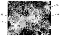
- FIG. 2 is a micrograph showing an example of a sintered compact structure of a wear resistant sliding bearing made of a sintered compact according to an example of the present invention.
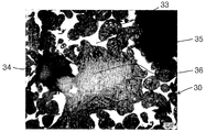
- FIG. 3 is a micrograph showing an example of a sintered compact structure of a wear resistant sliding bearing made of a sintered compact according to an example of the present invention.
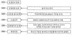
- FIG. 4 is a process chart showing an example of the manufacturing process of the wear-resistant slide bearing made of the sintered compact according to the present invention.
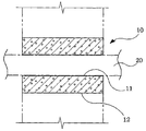
- the bush-type sliding bearing 10 as shown in FIG. 1 has a body 12 having an inner diameter portion 11 formed therein, and the inner diameter portion 11 of the body 12 includes:
- the shaft 20 is rotatably inserted.
- the sliding bearing according to the present invention has 7 to 20% by weight of copper (Cu), 1 to 7% by weight of tin (Sn), 0.2 to 2.0% by weight of carbon (C), and 0.3 to 0.3% by weight of nickel (Ni). It has a sintered body form which is manufactured by sintering the composition for sliding bearing containing 4 weight%, 0.01-0.4 weight% of boron (B), and remainder iron (Fe).
- the sliding bearing composition is 0.02 to 0.6% by weight of chromium (Cr), 0.05 to 0.5% by weight of molybdenum (Mo), 0.01 to 0.3% by weight of vanadium (V), tungsten (W) 0.05 to 0.5% by weight, manganese (Mn) 0.01 to 0.05% by weight and silicon (Si) may further include one or more selected from the group consisting of 0.02 to 0.2% by weight.
- the components are copper (Cu), tin (Sn), carbon (C), nickel, boron (B), iron (Fe), chromium (Cr), molybdenum (Mo), vanadium (V) , Tungsten (W), manganese (Mn) and silicon (Si) are used in powder form, and commercially available powders can be purchased and used.
- the components may be used as individual powders, or an alloy powder in which two or more components are present in an alloy form may be purchased. When using alloy powder, the proportion of each component in the alloy powder should be calculated to determine the amount added for each component.
- the composition for sintering the sliding bearing 10 may prepare the sliding bearing 10 by preparing each component in a powder state at a weight ratio and then molding and sintering the components.
- the sliding bearing according to the present invention may be referred to as a bearing mainly composed of iron (Fe), copper (Cu) and tin (Sn).
- Copper (Cu) is added to the iron (Fe) -based small binder to serve as a binder of the iron (Fe) powder as well as to maintain a low friction properties.
- the content of copper is less than 7% by weight, the low friction property is deteriorated, and when the content of copper is more than 20% by weight, the hardness of the sintered body may be lowered.
- tin (Sn) in order for tin (Sn) to form an intermetallic compound between Cu and Sn in the sintered body, it is effective to add tin (Sn) in the form of a copper-tin (Cu-Sn) alloy. That is, according to an example of the present invention, the tin (Sn) may be included in the form of an alloy (Cu-Sn) powder of copper and tin. As the alloy (Cu-Sn) powder of copper and tin, one having a content of tin (Sn) of about 25 to 50% by weight may be used.
- tin a small amount thereof may be supplied by a copper-tin alloy, but in the case of copper (Cu), a sufficient amount may not be supplied by the copper-tin alloy.
- copper powder may be added separately or an alloy powder of copper and another metal may be added.
- the hardness may be lowered due to a decrease in the content of iron (Fe) particles.
- the total content of the copper (Cu) powder and the copper-tin (Cu-Sn) alloy powder is less than 8% by weight, the densification and alloying of the iron (Fe) particles may be lowered, thereby reducing the rigidity. Therefore, preferably, the sum of the copper (Cu) powder and the copper-tin (Cu-Sn) alloy powder is preferably in the range of 8 to 27% by weight based on the total weight of the powder.
- nickel In the case of nickel (Ni), it may be used as a powder in the form of nickel (Ni) alone, or in the form of an alloy powder together with other components, for example, boron (B), chromium (Cr), and silicon (Si). It may be. When used in the form of alloy powder, the sinterability may be improved.
- chromium (Cr), silicon (Si) which can be decomposed during sintering to provide boron (B) It may be used in the form of an alloy powder with nickel (Ni), and in some cases may be provided in the form of carbides or other borides such as B 4 C. That is, the boron is at least one type selected from the group consisting of boron (B) alone, B 4 C type carbide, B-Ni type boride, B-Cr type boride and B-Si type boride It may be provided as.
- Chromium (Cr) and silicon (Si) form an alloy with the nickel (Ni) and boron (B) to be added in the form of alloy powder.
- the chromium (Cr) is an element for forming microcarbide, and when added in an amount less than 0.02% by weight, the effect is negligible. If it is more than 0.6% by weight, the material may be brittle.
- the silicon (Si) may be mixed with the nickel (Ni), boron (B), chromium (Cr), etc., and may serve to lower the melting temperature of the alloy powder, the silicon (Si) may be added to facilitate powder production. have. In the case of the present invention, it is preferable to add 0.02 to 0.2% by weight to the total weight of the sliding bearing sintering composition.
- Chromium (Cr), molybdenum (Mo), vanadium (V), tungsten (W), manganese (Mn) and silicon (Si) powders are sometimes classified as tool steel powders, which are made of only iron (Fe) particles. As harder particles than martensite, it is added to and dispersed in an alloy based on iron (Fe), thereby reducing plastic deformation of the substrate and enhancing wear resistance.
- the content range of the tool steel powder is determined in consideration of all of the increase in hardness, the effect of wear resistance, and sintering, etc., if less than the content range is less improvement in hardness and wear resistance, while the content exceeds the content range As this increases, the bearing has a characteristic of attacking the relative material, and more seriously, the sintering performance is degraded.
- the plurality of pores 34 formed in the sintered body 30 may act as a space for impregnating the lubricating oil. Such pores are formed in the process of molding and sintering the powder composition. Lubricating oil may be impregnated in the pores 34 so that the bearing may have better lubrication characteristics. Such lubricating oils may further include antiwear additives, and may further include solid lubricants. The lubrication characteristics of the bearing may be improved by the wear resistant extreme pressure additive or the solid lubricant.
- a lubricating oil having a kinematic viscosity in the range of 80 to 1,000 cSt, more preferably about 80 to 240 cSt, and having a viscosity index of 150 to 280 can be used. If the kinematic viscosity is less than 80 cSt, it is too sticky so that the lubricant does not flow well to the friction surface when used in the bearing. If the viscosity exceeds 1,000 cst, the lubricant becomes too thin to stay in the pores. It is advantageous that the viscosity is preferably 240 cSt or less.
- the bearing 10 impregnated with lubricating oil is subjected to extremely harsh conditions, for example, a high surface pressure of about 3 to 8 kgf / mm2 and a 0.5 to Lubricating oil can maintain a constant viscosity even when the temperature rises by using it at a low speed condition of about 8 cm / sec.
- the lubricating oil can be added a wear-resistant extreme pressure additive that reacts with the metal surface to form a thin film.
- the wear resistant extreme pressure additive prevents direct contact between the shaft 20 and the bearing 10 by forming a thin film in response to the surface of the shaft 20.
- the frictional resistance between the shaft 20 and the bearing 10 is significantly reduced, and the frictional resistance between the shaft 20 and the bearing 10 is remarkably reduced.
- By reducing the wear resistance of the bearing 10 is improved.
- the wear-resistant extreme pressure additive for example, zinc dithiophosphate, amine phosphate (Amine Phosphate), thiocarbamates, sulfur compounds (Sulfur Compounds), phosphorus compounds (Phosphorus Compounds) and One or more selected from the group consisting of boron compounds can be used.
- the wear resistant extreme pressure additive may be added by 0.4 to 6.8% by volume relative to the total volume of the lubricating oil to be impregnated.
- the lubricant may further include a solid lubricant.
- the solid lubricant is a lubricant in solid powder or in a solid state which can be lubricated by the internal sliding of the grain crystal itself, the sliding between the particles, and the sliding of the friction surface of the particles.
- Examples of such solid lubricants include graphite, sulfide-based materials such as molybdenum disulfide (MoS 2 ), or resin-based materials such as polytetrafluoroethylene, Teflon, and one or more of them. In order to see the effect of this solid lubricant can be added by 1.5 to 25% by volume relative to the total volume of the lubricating oil impregnated.
- a powder for the sliding bearing composition is prepared. Specifically, 7 to 20% by weight of copper (Cu), 1 to 7% by weight of tin (Sn), 0.2 to 2.0% by weight of carbon (C), 0.3 to 4% by weight of nickel (Ni), and boron (B) 0.01 to 0.4% by weight and the residual amount of iron (Fe) is prepared in a powder state (S10).
- chromium Cr
- Mo molybdenum
- V vanadium
- W tungsten
- Mn Manganese
- Si silicon
- the components may use commercially available powdered products.
- the powder may be commercially available for each component, and may be commercially available as an alloy powder.
- the content of each constituent powder should be calculated in consideration of the content of each component included in the alloy.
- the powder prepared as described above is mixed using a wet or dry mixing method (S20), and then a molded body is manufactured by a pressing process (S30).
- the shape of the molded body there is no particular limitation on the shape of the molded body, and may be molded in accordance with the shape of the sliding material (Sliding).
- sliding material sliding material
- the applied pressure may be about 300 to 5,000 kg / cm 2 .
- the molded body is sintered by heating and sintering at a temperature of 1000 ° C. to 1150 ° C. for 15 to 50 minutes in a vacuum or gas atmosphere to prevent oxidation (S40).
- the sintered body is vacuum impregnated with lubricating oil (S60).
- the molded body was heated and sintered for 25 minutes at a temperature of 1100 ° C. in a gas atmosphere to prepare a sintered body.
- the sintering temperature and the holding time of 1100 ° C. are the sintering temperatures suitable for all of the samples of Examples 1-3 and Comparative Examples 1-7.
- Hardness was measured for the bush-type bearings manufactured in Examples 1-3 and Comparative Examples 1-7.
- the said hardness measurement was measured using the hardness measuring machine used for the hardness measurement of a normal sintered compact. In this case, hardness was measured by distinguishing between the group subjected to carburization heat treatment and the group without carburizing heat treatment at 900 ° C. after sintering in Examples 1-3 and Comparative Examples 1-7. The results are shown in Table 3 below.
- Comparative Example 1 is an alloy for reinforcing the matrix of Fe in the conventional composition, it can be seen that the hardness is very low because there is no Sn for reinforcing Cu.
- Comparative Example 5 also included a Cu-Sn alloy powder and Ni and B powder, but the hardness was increased, but because of the high content of Ni and B, the formation of pores was unstable and brittleness occurred.
- test results show that the hardness after carburizing heat treatment is much higher than before carburizing heat treatment.
- the case after the heat treatment, such as carburizing heat treatment step is excellent in load-bearing force and can prevent plastic deformation even at high surface pressure.
- the frictional wear characteristics of the bush-type sliding bearings manufactured in Examples 1-3 and Comparative Examples 1-7 were tested.
- the friction coefficient was measured using a manufactured tester using the manufactured bearing as a bush and mounting a pin therein. Cycles in which sintering occurred and the coefficient of friction became 0.3 or more were set as the feeding cycle.
- the amount of wear was evaluated by the height difference by measuring the surface roughness inside the bearing after completion of the test.
- the friction wear characteristics test was performed only for the group subjected to carburizing heat treatment at 900 ° C. after sintering among the groups prepared in Examples 1-3 and Comparative Examples 1-7.
- the high surface pressure condition was tested while maintaining a pressure of 10 kg / mm2 higher than 2-5 kg / mm2, which is a general bush use condition, and the speed was 5 cm / sec.
- the operating temperature was maintained at about 50 ° C. in order to grasp the effect of the viscosity of the grease at a constant state, and injected only once before the test using the lithium-based grease as the grease.
- Example 1 of Comparative Example 1 of Table 4 when comparing the test results of Example 1 and Comparative Example 1 of Table 4, even if lubricating oil, wear-resistant extreme pressure additive and a solid lubricant are added to the bearing according to Comparative Example 1 was prepared in Example 1 of the present invention It can be seen that the feeding cycle is shorter than the case where the lubricant, the wear resistant extreme pressure additive and the solid lubricant are not added to the bearing.
- the bearing manufactured by the bearing sintered body according to the present invention not only the friction characteristics of the iron-based shaft are improved, but also the high-strength boride is formed in the Fe particles, which are matrix sintered, and Cu- Since the Sn intermetallic compound is formed, plastic deformation can be prevented even at high surface pressure.
- a certain amount of hard alloy it may be combined with other compositions to further improve hardness and friction performance.
Landscapes
- Chemical & Material Sciences (AREA)
- Engineering & Computer Science (AREA)
- Mechanical Engineering (AREA)
- General Engineering & Computer Science (AREA)
- Materials Engineering (AREA)
- Metallurgy (AREA)
- Organic Chemistry (AREA)
- Oil, Petroleum & Natural Gas (AREA)
- Sliding-Contact Bearings (AREA)
- Powder Metallurgy (AREA)
Abstract
Description
| 성분 | Fe | Cu | Cu30Sn | C | Ni | B | Si | Cr | Mo | V | W | Mn |
| 실시예 1 | Bal. | 15 | 5 | 1 | 0.5 | 0.1 | 0.03 | 0.05 | ||||
| 실시예 2 | Bal. | 10 | 10 | 1 | 1.2 | 0.2 | 0.07 | 0.1 | ||||
| 실시예 3 | Bal. | 10 | 10 | 1 | 1.2 | 0.2 | 0.1 | 0.3 | 0.3 | 0.1 | 0.3 | 0.03 |
| 비교예 1 | Bal. | 20 | 1 | |||||||||
| 비교예 2 | Bal. | 20 | 1 | 1.2 | 0.2 | 0.07 | 0.1 | |||||
| 비교예 3 | Bal. | 30 | 1 | 1.2 | 0.2 | 0.07 | 0.1 | |||||
| 비교예 4 | Bal. | 10 | 10 | 1 | 0.2 | 0.01 | 0.01 | 0.02 | ||||
| 비교예 5 | Bal. | 10 | 10 | 1 | 5 | 0.5 | 0.3 | 0.4 | ||||
| 비교예 6 | Bal. | 10 | 10 | 1 | 0.1 | 0.5 | 0.3 | 0.1 | 0.3 | 0.03 | ||
| 비교예 7 | Bal. | 10 | 10 | 1 | 1.2 | 0.2 | 0.1 | 1.0 | 0.6 | 0.4 | 0.6 | 0.06 |
| 성분 | 소결후 침탄열처리를 한 경우의 경도(HrB) | 소결후 침탄열처리가 안된 경우의 경도(HrB) | 기공율 (부피%) | 비고 |
| 실시예 1 | 90 | 51 | 19.5 | |
| 실시예 2 | 92 | 54 | 19.2 | |
| 실시예 3 | 94 | 59 | 19.7 | |
| 비교예 1 | 76 | 38 | 19.6 | |
| 비교예 2 | 80 | 41 | 21.1 | |
| 비교예 3 | 71 | 33 | 20.0 | |
| 비교예 4 | 86 | 45 | 19.0 | |
| 비교예 5 | 87 | 67 | 29.6 | 취성발생 |
| 비교예 6 | 84 | 45 | 20.9 | |
| 비교예 7 | 90 | 52 | 25.2 |
| 성분 | 윤활유함침여부(부피%) | 마찰계수가 0.3이상이 되는 cycles (급지주기) | 핀 마모량(mm) | 부시마모량(mm) |
| 실시예 1 | 미실시 | 67,000 | 0.21mm | 0.20mm |
| 실시예 2 | 미실시 | 71,000 | 0.19mm | 0.15mm |
| 실시예 3 | 미실시 | 75,000 | 0.23mm | 0.14mm |
| 비교예 1 | 미실시 | 39,000 | 0.35mm | 0.31mm |
| 비교예 2 | 미실시 | 46,000 | 0.31mm | 0.29mm |
| 비교예 3 | 미실시 | 37,000 | 0.29mm | 0.45mm |
| 비교예 4 | 미실시 | 51,000 | 0.30mm | 0.21mm |
| 비교예 5 | - | - | - | - |
| 비교예 6 | 미실시 | 54,000 | 0.37mm | 0.20mm |
| 비교예 7 | 미실시 | 66,000 | 0.42mm | 0.19mm |
| 성분 | 윤활유 함침(부피%) | 내마모극압성 첨가제(부피%) | 고체윤활제(부피%) | 마찰계수가 0.3 이상 되는 cycles | 비고 |
| 실시예 1 | 미실시 | 미첨가 | 미첨가 | 67,000 | |
| 실시(15%, 221cSt) | 미첨가 | 미첨가 | 93,000 | ||
| 실시(15%, 221cSt) | 첨가(2%) | 미첨가 | 108,000 | ||
| 실시(15%, 600cSt) | 첨가(2%) | 미첨가 | 80,000 | ||
| 실시(15%, 221cSt) | 첨가(2%) | 첨가(4%) | 112,000 | ||
| 실시예 2 | 실시(15%, 221cSt) | 첨가(2%) | 첨가(4%) | 121,000 | |
| 비교예 1 | 미실시 | 미첨가 | 미첨가 | 39,000 | |
| 실시(15%, 221cSt) | 미첨가 | 미첨가 | 51,000 | ||
| 실시(15%, 221cSt) | 첨가(2%) | 미첨가 | 61,000 | ||
| 실시(15%, 600cSt) | 첨가(2%) | 미첨가 | 48,000 | ||
| 실시(15%, 221cSt) | 첨가(2%) | 첨가(4%) | 65,000 | ||
| 비교예 2 | 실시(15%, 221cSt) | 첨가(2%) | 첨가(4%) | 78,000 |
Claims (11)
- 전체 중량에 대하여 구리(Cu) 7~20중량%, 주석(Sn) 1~7중량%, 탄소(C) 0.2~ 2.0중량%, 니켈(Ni) 0.3~4중량%, 붕소(B) 0.01~0.4중량% 및 잔량의 철(Fe)을 포함하는 슬라이딩 베어링용 조성물을 소결하여 형성된 슬라이딩 베어링.
- 제 1항에 있어서, 상기 슬라이딩 베어링은 내경부를 구비한 몸체를 가지며, 상기 내경부에는 축이 회전 가능하도록 삽입되는, 부시(bush)타입인 것을 특징으로 하는 슬라이딩 베어링.
- 제 1항에 있어서, 상기 슬라이딩 베어링 조성물은 전체 중량에 대하여 크롬(Cr) 0.02~0.6중량%, 몰리브덴(Mo) 0.05~0.5중량%, 바나듐(V) 0.01~0.3중량%, 텅스텐(W) 0.05~0.5중량%, 망간(Mn) 0.01~0.05중량% 및 실리콘(Si) 0.02~0.2중량%로 이루어진 군에서 선택된 1종 이상을 더 포함하는 것을 특징으로 하는 슬라이딩 베어링.
- 제 1항 내지 제 3항 중 어느 한 항에 있어서,상기 슬라이딩 베어링 조성물에서 상기 주석(Sn)은 구리-주석의 합금(Cu-Sn) 분말형태로 포함되며, 상기 구리-주석의 합금에서 상기 주석의 함량은 20~50중량%인 것을 특징으로 하는 슬라이딩 베어링.
- 제 1항에 있어서, 상기 슬라이딩 베어링은 전체 부피에 대하여 15 내지 25 부피%만큼의 기공이 내부에 형성되어 있는 것을 특징으로 하는 슬라이딩 베어링.
- 제 5항에 있어서, 상기 기공에는 윤활유가 함침되어 있으며, 상기 윤활유는 40℃에서 80~240cSt 범위의 동점도와 150~280의 점도지수를 가지는 것을 특징으로 하는 슬라이딩 베어링.
- 제 6항에 있어서, 상기 윤활유는 아연 티오 인산염, 아민 인산염, 티오카바메이트, 황 화합물, 인 화합물 및 붕소 화합물로 이루어진 군에서 선택된 적어도 1종 이상의 내마모성 극압성 첨가제를 윤활유 총 부피에 대하여 0.4~6.8부피%만큼 포함하는 것을 특징으로 하는 슬라이딩 베어링.
- 제 6항 또는 제 7항에 있어서, 상기 윤활유는 흑연, 이황화몰리브덴(MoS2), 폴리테트라 플루오르 에틸렌 및 테프론으로 이루어진 군에서 선택된 적어도 1종 이상의 고체윤활제를 윤활유의 총 부피에 대하여 1.5~ 25부피%만큼 포함하는 것을 특징으로 하는 슬라이딩 베어링.
- 전체 중량에 대하여 구리(Cu) 7~20중량%, 주석(Sn) 1~7중량%, 탄소(C) 0.2~ 2.0중량%, 니켈(Ni) 0.3~4중량%, 붕소(B) 0.01~0.4중량% 및 잔량의 철(Fe)을 포함하는 슬라이딩 베어링 조성물용 분말을 준비하는 분말 준비단계 (S10);상기 준비된 분말을 혼합하는 분말 혼합단계(S20);상기 혼합된 분말을 가압하여 축 삽입용 내경부가 구비된 부시 타입 베어링의 가압 성형체를 제조하는 성형체 제조단계(S30);상기 성형체를 1000℃ 내지 1150℃의 온도로 15~50분간 가열하면서 소결하여 소결체를 제조하는 소결단계(S40);상기 소결체를 침탄열처리, 질화열처리 및 고주파열처리로 이루어진 군에서 선택된 적어도 1종 이상의 열처리방법으로 처리하여 미세조직을 강화시키는 강화 열처리단계(S50); 및상기 강화된 소결체에 윤활유를 함침시키는 함침단계 (S60);를 포함하는 부시타입 슬라이딩 베어링의 제조방법.
- 제 9항에 있어서, 분말 준비단계에서 전체 중량에 대하여 크롬(Cr) 0.02~0.6중량%, 몰리브덴(Mo) 0.05~0.5중량%, 바나듐(V) 0.01~0.3중량%, 텅스텐(W) 0.05~ 0.5중량%, 망간(Mn) 0.01~0.05중량% 및 실리콘(Si) 0.02~0.2중량%로 이루어진 군에서 선택된 1종 이상의 분말을 더 준비하여 상기 조성물에 포함시키는 것을 특징으로 하는 부시타입 슬라이딩 베어링의 제조방법.
- 제 9 항 또는 제10항에 있어서,상기 슬라이딩 베어링 조성물에서 상기 주석(Sn)은 구리-주석의 합금(Cu-Sn) 분말형태로 포함되며, 상기 구리-주석의 합금에서 상기 주석의 함량은 20~50중량%인 것을 특징으로 하는 슬라이딩 베어링의 제조방법.
Priority Applications (4)
| Application Number | Priority Date | Filing Date | Title |
|---|---|---|---|
| CN200980142126.XA CN102197150B (zh) | 2008-10-23 | 2009-10-22 | 耐磨性得到提高的滑动轴承及其制造方法 |
| US13/125,727 US9631263B2 (en) | 2008-10-23 | 2009-10-22 | Sliding bearing with improved wear resistance and method of manufacturing same |
| EP09822220.1A EP2357258B1 (en) | 2008-10-23 | 2009-10-22 | Sliding bearing with improved wear resistance and method of manufacturing same |
| JP2011533108A JP5378530B2 (ja) | 2008-10-23 | 2009-10-22 | 耐摩耗性が向上した滑り軸受け及びその製造方法 |
Applications Claiming Priority (2)
| Application Number | Priority Date | Filing Date | Title |
|---|---|---|---|
| KR10-2008-0104283 | 2008-10-23 | ||
| KR1020080104283A KR101533458B1 (ko) | 2008-10-23 | 2008-10-23 | 내마모성이 향상된 슬라이딩 베어링 및 그 제조방법 |
Publications (2)
| Publication Number | Publication Date |
|---|---|
| WO2010047544A2 true WO2010047544A2 (ko) | 2010-04-29 |
| WO2010047544A3 WO2010047544A3 (ko) | 2010-07-15 |
Family
ID=42119844
Family Applications (1)
| Application Number | Title | Priority Date | Filing Date |
|---|---|---|---|
| PCT/KR2009/006124 WO2010047544A2 (ko) | 2008-10-23 | 2009-10-22 | 내마모성이 향상된 슬라이딩 베어링 및 그 제조방법 |
Country Status (6)
| Country | Link |
|---|---|
| US (1) | US9631263B2 (ko) |
| EP (1) | EP2357258B1 (ko) |
| JP (1) | JP5378530B2 (ko) |
| KR (1) | KR101533458B1 (ko) |
| CN (1) | CN102197150B (ko) |
| WO (1) | WO2010047544A2 (ko) |
Families Citing this family (18)
| Publication number | Priority date | Publication date | Assignee | Title |
|---|---|---|---|---|
| CN102994879A (zh) * | 2012-11-22 | 2013-03-27 | 宁波市群星粉末冶金有限公司 | 一种粉末冶金的无油润滑轴承及制备方法 |
| CN103008665B (zh) * | 2012-11-25 | 2014-07-09 | 安徽普源分离机械制造有限公司 | 一种旋塞阀阀瓣的制备工艺 |
| CN105009425B (zh) | 2013-03-25 | 2019-01-04 | Ntn株式会社 | 烧结轴承及其制造方法、以及具有该烧结轴承的振动电机 |
| JP6194613B2 (ja) * | 2013-03-29 | 2017-09-13 | 日立化成株式会社 | 摺動部材用鉄基焼結合金およびその製造方法 |
| CN105463243A (zh) * | 2015-11-24 | 2016-04-06 | 无锡市东赫金属制品有限公司 | 滑动轴承合金材料及其制备方法 |
| CN106041096A (zh) * | 2016-06-27 | 2016-10-26 | 滁州帝邦科技有限公司 | 一种水冷箱用耐磨耐腐蚀轴承套制备方法 |
| JP6817094B2 (ja) * | 2016-07-29 | 2021-01-20 | 株式会社ダイヤメット | 鉄銅基焼結含油軸受及びその製造方法 |
| JP6849459B2 (ja) * | 2017-02-02 | 2021-03-24 | 株式会社神戸製鋼所 | 粉末冶金用混合粉末 |
| US10563695B2 (en) * | 2017-04-14 | 2020-02-18 | Tenneco Inc. | Multi-layered sintered bushings and bearings |
| CN107228128A (zh) * | 2017-05-25 | 2017-10-03 | 合肥皖化电泵有限公司 | 一种bcp泵用耐磨自散热导轴承 |
| CN107663615B (zh) * | 2017-09-13 | 2019-05-03 | 湖南屹林材料技术有限公司 | 一种高强度高自润滑铁基合金及制备方法和应用 |
| JP6935503B2 (ja) | 2017-09-20 | 2021-09-15 | 株式会社ダイヤメット | 焼結含油軸受 |
| EP3471510A1 (de) | 2017-10-11 | 2019-04-17 | Gottfried Wilhelm Leibniz Universität Hannover | Vorrichtung zur induktiven erwärmung |
| CN108149061B (zh) * | 2017-12-29 | 2019-11-26 | 中国第一汽车股份有限公司 | 一种用于湿式同步器齿环的铜基粉末冶金摩擦材料 |
| JP2021060077A (ja) * | 2019-10-07 | 2021-04-15 | Ntn株式会社 | 焼結含油軸受 |
| DE102020202739A1 (de) * | 2020-03-04 | 2021-09-09 | Mahle International Gmbh | Gesintertes Lagerbuchsenmaterial, Gleitlager, Brennkraftmaschine und elektrische Maschine |
| DE102020202738A1 (de) * | 2020-03-04 | 2021-09-09 | Mahle International Gmbh | Gleitlager, Verfahren zum Herstellen eines Gleitlagers, Brennkraftmaschine mit Gleitlager sowie elektrische Maschine mit Gleitlager |
| CN111664182A (zh) * | 2020-05-26 | 2020-09-15 | 南京理工大学 | 一种粉末冶金自润滑含油轴承及其制备方法 |
Citations (1)
| Publication number | Priority date | Publication date | Assignee | Title |
|---|---|---|---|---|
| KR100261369B1 (ko) | 1993-10-22 | 2000-07-01 | 세구찌 류이찌 | 미끄럼 베어링 조립체 |
Family Cites Families (8)
| Publication number | Priority date | Publication date | Assignee | Title |
|---|---|---|---|---|
| JP3168538B2 (ja) * | 1997-04-19 | 2001-05-21 | チャン リー ウー | 滑りベアリング及びその製造方法 |
| CN101701322B (zh) | 2003-07-31 | 2014-03-19 | 株式会社小松制作所 | 烧结滑动部件 |
| KR101094758B1 (ko) * | 2004-11-22 | 2011-12-16 | 두산인프라코어 주식회사 | 소결베어링 제조방법 |
| GB2437216A (en) * | 2005-01-31 | 2007-10-17 | Komatsu Mfg Co Ltd | Sintered material, iron-based sintered sliding material and process for producing the same |
| WO2007086621A1 (ja) * | 2006-01-30 | 2007-08-02 | Komatsu Ltd. | 鉄系焼結複層巻ブッシュ、その製造方法及び作業機連結装置 |
| KR101240051B1 (ko) | 2006-11-20 | 2013-03-06 | 두산인프라코어 주식회사 | 내마모성 베어링 및 그 제조방법 |
| JP4886545B2 (ja) | 2007-02-22 | 2012-02-29 | 日立粉末冶金株式会社 | 焼結含油軸受およびその製造方法 |
| CN100473481C (zh) | 2007-08-24 | 2009-04-01 | 包敢锋 | 粉末冶金Fe-Cu-Sn含油轴承及其生产工艺 |
-
2008
- 2008-10-23 KR KR1020080104283A patent/KR101533458B1/ko active IP Right Grant
-
2009
- 2009-10-22 JP JP2011533108A patent/JP5378530B2/ja not_active Expired - Fee Related
- 2009-10-22 US US13/125,727 patent/US9631263B2/en active Active
- 2009-10-22 WO PCT/KR2009/006124 patent/WO2010047544A2/ko active Application Filing
- 2009-10-22 CN CN200980142126.XA patent/CN102197150B/zh not_active Expired - Fee Related
- 2009-10-22 EP EP09822220.1A patent/EP2357258B1/en active Active
Patent Citations (1)
| Publication number | Priority date | Publication date | Assignee | Title |
|---|---|---|---|---|
| KR100261369B1 (ko) | 1993-10-22 | 2000-07-01 | 세구찌 류이찌 | 미끄럼 베어링 조립체 |
Non-Patent Citations (1)
| Title |
|---|
| See also references of EP2357258A4 |
Also Published As
| Publication number | Publication date |
|---|---|
| JP2012506494A (ja) | 2012-03-15 |
| EP2357258A4 (en) | 2016-09-21 |
| JP5378530B2 (ja) | 2013-12-25 |
| US20110243484A1 (en) | 2011-10-06 |
| KR101533458B1 (ko) | 2015-07-03 |
| CN102197150A (zh) | 2011-09-21 |
| CN102197150B (zh) | 2014-09-17 |
| EP2357258B1 (en) | 2018-08-15 |
| WO2010047544A3 (ko) | 2010-07-15 |
| EP2357258A2 (en) | 2011-08-17 |
| KR20100045203A (ko) | 2010-05-03 |
| US9631263B2 (en) | 2017-04-25 |
Similar Documents
| Publication | Publication Date | Title |
|---|---|---|
| WO2010047544A2 (ko) | 내마모성이 향상된 슬라이딩 베어링 및 그 제조방법 | |
| KR101240051B1 (ko) | 내마모성 베어링 및 그 제조방법 | |
| WO2012067378A2 (ko) | 윤활 특성이 향상된 슬라이딩 베어링 | |
| JP3168538B2 (ja) | 滑りベアリング及びその製造方法 | |
| WO2012074276A2 (ko) | 소결 베어링 및 그 제조방법 | |
| KR20080078537A (ko) | 소결 함유 베어링 및 그 제조방법 | |
| CN109702199A (zh) | 一种高熵合金基自润滑含油轴承材料 | |
| CN101370950A (zh) | 铜类烧结滑动部件 | |
| JPH05279772A (ja) | 耐摩耗性摺動合金、摺動部材およびその製造方法 | |
| WO2010071373A2 (ko) | 소결 부시 | |
| DE102010019587B4 (de) | Wälzlager | |
| JPH07118777A (ja) | 摺動部材 | |
| KR100286246B1 (ko) | 미끄럼베어링 및 그 제조방법 | |
| JP4619302B2 (ja) | すべり軸受及びその製造方法 | |
| EP4112208A1 (en) | Bushing manufacturing method, bushing, and excavator | |
| WO2022092468A1 (ko) | 미세조직이 개량된 고력황동 합금이 적용된 고면압용 오일리스 베어링 | |
| JP5595998B2 (ja) | 固溶または固溶及び分散強化金属系自己潤滑性複合材料 | |
| US6833018B1 (en) | Powder metal materials including glass | |
| WO2010140750A1 (ko) | 자기윤활 베어링용 Fe 합금, 그 제조방법 및 이로부터 제조된 자기윤활 베어링 | |
| JPS6119849B2 (ko) | ||
| KR100261059B1 (ko) | 동계 소결합금부재의 제조방법 | |
| JP2020183568A (ja) | 建設機械の関節用ブッシュ | |
| Wiśniewska-Weinert | Tribologiczne właściwości wyrobów wykonanych z siarczkowych nanokompozytów |
Legal Events
| Date | Code | Title | Description |
|---|---|---|---|
| WWE | Wipo information: entry into national phase |
Ref document number: 200980142126.X Country of ref document: CN |
|
| 121 | Ep: the epo has been informed by wipo that ep was designated in this application |
Ref document number: 09822220 Country of ref document: EP Kind code of ref document: A2 |
|
| WWE | Wipo information: entry into national phase |
Ref document number: 2011533108 Country of ref document: JP Ref document number: 13125727 Country of ref document: US |
|
| NENP | Non-entry into the national phase |
Ref country code: DE |
|
| WWE | Wipo information: entry into national phase |
Ref document number: 2009822220 Country of ref document: EP |