WO2010044293A1 - 無線通信装置及び無線通信方法 - Google Patents
無線通信装置及び無線通信方法 Download PDFInfo
- Publication number
- WO2010044293A1 WO2010044293A1 PCT/JP2009/062472 JP2009062472W WO2010044293A1 WO 2010044293 A1 WO2010044293 A1 WO 2010044293A1 JP 2009062472 W JP2009062472 W JP 2009062472W WO 2010044293 A1 WO2010044293 A1 WO 2010044293A1
- Authority
- WO
- WIPO (PCT)
- Prior art keywords
- antenna
- node
- wireless communication
- unit
- nodes
- Prior art date
- Legal status (The legal status is an assumption and is not a legal conclusion. Google has not performed a legal analysis and makes no representation as to the accuracy of the status listed.)
- Ceased
Links
Images




Classifications
-
- H—ELECTRICITY
- H04—ELECTRIC COMMUNICATION TECHNIQUE
- H04B—TRANSMISSION
- H04B7/00—Radio transmission systems, i.e. using radiation field
- H04B7/02—Diversity systems; Multi-antenna system, i.e. transmission or reception using multiple antennas
- H04B7/04—Diversity systems; Multi-antenna system, i.e. transmission or reception using multiple antennas using two or more spaced independent antennas
- H04B7/08—Diversity systems; Multi-antenna system, i.e. transmission or reception using multiple antennas using two or more spaced independent antennas at the receiving station
- H04B7/0802—Diversity systems; Multi-antenna system, i.e. transmission or reception using multiple antennas using two or more spaced independent antennas at the receiving station using antenna selection
- H04B7/0805—Diversity systems; Multi-antenna system, i.e. transmission or reception using multiple antennas using two or more spaced independent antennas at the receiving station using antenna selection with single receiver and antenna switching
- H04B7/0814—Diversity systems; Multi-antenna system, i.e. transmission or reception using multiple antennas using two or more spaced independent antennas at the receiving station using antenna selection with single receiver and antenna switching based on current reception conditions, e.g. switching to different antenna when signal level is below threshold
-
- H—ELECTRICITY
- H04—ELECTRIC COMMUNICATION TECHNIQUE
- H04W—WIRELESS COMMUNICATION NETWORKS
- H04W40/00—Communication routing or communication path finding
- H04W40/02—Communication route or path selection, e.g. power-based or shortest path routing
- H04W40/04—Communication route or path selection, e.g. power-based or shortest path routing based on wireless node resources
- H04W40/06—Communication route or path selection, e.g. power-based or shortest path routing based on wireless node resources based on characteristics of available antennas
Definitions
- the present invention relates to a radio communication apparatus and a radio communication method for selecting an optimum antenna for another node in a network (hereinafter referred to as an ad hoc network) configured only by nodes that can be connected wirelessly without requiring an access point. .
- the optimal communication route is selected and the gateway route is secured among the multiple nodes in the ad hoc network in the changing radio wave condition.
- selection of an antenna to be used in one node having a plurality of antennas is important for securing a gateway route.
- a conventional wireless communication network has a plurality of antennas having directivities in different directions on the transmission side, and selects and transmits the optimum antenna for each communication partner.
- the optimum antenna is selected so that the received signal level on the receiving side is maximized.
- the process of selecting the optimum antenna is performed by a process different from the data transmission (see, for example, Patent Document 1).
- the workstation determines the optimum transmission antenna for each server and stores (fixes) it in the transmission antenna table, it uses the fixed transmission antenna for each server to perform wireless communication. It is carried out. For this reason, even when the radio wave condition between the workstation and the server changes and the wireless quality due to the fixed transmission antenna deteriorates (when the wireless quality is better when another transmission antenna is used), There was a problem of continuing to use poor quality transmission antennas.
- the conventional wireless communication network is likely to cause non-delivery to the server and re-transmission due to the use of a transmission antenna with poor wireless quality, and cannot perform comfortable communication for the user. There was a problem.
- the present invention has been made to solve the above-described problems, and uses the same antenna as the antenna (the antenna having the best radio quality at the time of reception) selected by receiving radio waves from other nodes.
- the present invention provides a wireless communication apparatus and a wireless communication method that can transmit radio waves to the other nodes and perform communication with good wireless quality.
- the wireless communication apparatus selects one antenna according to the radio field strength among a plurality of antennas that transmit and receive radio waves to and from other nodes and antennas that receive radio waves from the other nodes.
- the antenna selection unit, the antenna information association unit for associating the one node with the other node that has received the radio wave by the one antenna selected by the antenna selection unit, and the antenna information association unit And a use antenna determining unit that determines an antenna that transmits a radio wave to another node based on the other node and antenna information.
- the disclosed wireless communication device transmits radio waves to other nodes using the same antenna as the antenna selected by receiving radio waves from other nodes (the antenna having the best radio quality at the time of reception). Therefore, there is an effect that communication with good radio quality can be performed.
- each time the antenna information association unit receives a radio wave from another node the other node is associated with the one antenna.
- the disclosed wireless communication device can transmit radio waves to other nodes by using an optimum antenna for each radio wave reception, and can perform communication with better radio quality.
- each of the antennas used by the antenna determination unit receives radio waves from other nodes based on information on other nodes and antennas associated by the antenna information association unit.
- the appearance frequency of the antenna is calculated, and the antenna to be transmitted is determined based on the appearance frequency.
- the antenna information association unit associates the value of the radio wave intensity at the time of radio wave reception of the antenna with the antenna
- the used antenna determination unit associates the antenna information with the antenna information.
- the antenna to be transmitted is determined based on information on other nodes, antennas, and radio field strengths associated with each other.
- the disclosed wireless communication apparatus can select an antenna having a stable received radio wave intensity.
- the wireless communication method according to the present invention is the wireless communication method by one node having a plurality of antennas for transmitting / receiving radio waves to / from other nodes among the plurality of nodes constituting the ad hoc network.
- An antenna information association step for associating the one antenna with each other, and an antenna to be used for determining an antenna for transmitting radio waves to other nodes based on information on other nodes and antennas associated by the antenna information association step Steps.
- the disclosed wireless communication method transmits radio waves to other nodes using the same antenna as the selected antenna (the antenna having the best radio quality at the time of reception). Therefore, there is an effect that communication with good radio quality can be performed.
- FIG. 1A is a schematic diagram illustrating a main configuration of the wireless ad hoc communication system according to the first embodiment
- FIG. 1B is an explanatory diagram for explaining an antenna of a node illustrated in FIG.
- FIG. 2 is a schematic diagram showing a main configuration of the wireless communication apparatus shown in FIG.
- FIG. 3 is an explanatory diagram illustrating an example of antenna information recorded in the antenna information storage unit illustrated in FIG. 2.
- FIG. 4 is a flowchart showing a processing procedure in the wireless communication apparatus shown in FIG. 5A is an explanatory diagram showing another example of the antenna information recorded in the antenna information storage unit shown in FIG. 2, and FIG. 5B shows the detailed contents of step S11 in the flowchart shown in FIG. It is a flowchart to show.
- 6A is an explanatory diagram illustrating another example of the antenna information recorded in the antenna information storage unit illustrated in FIG. 2, and FIG. 6B illustrates the detailed contents of step S11 in the flowchart illustrated in FIG. It is a flowchart to
- the present invention can also be implemented as a program and method usable on a computer.
- the present invention can be implemented in hardware, software, or software and hardware embodiments.
- the program can be recorded on any computer-readable medium such as a hard disk, CD-ROM, DVD-ROM, optical storage device, or magnetic storage device.
- the program can be recorded on another computer via a network.
- FIG. 1A is a schematic diagram illustrating a main configuration of the wireless ad hoc communication system according to the first embodiment
- FIG. 1B is an explanatory diagram for explaining an antenna of a node illustrated in FIG. 2 is a schematic diagram showing the main configuration of the wireless communication apparatus shown in FIG. 1
- FIG. 3 is an explanatory diagram showing an example of antenna information recorded in the antenna information storage unit shown in FIG. 2, and
- FIG. 4 is shown in FIG. It is a flowchart which shows the process sequence in a radio
- a wireless ad hoc communication system 100 can communicate with an ad hoc network 101 composed of only nodes 10 capable of wireless communication by mutually converting data of different media and protocols as a main configuration. And a server 103 that collects the status of each node 10 and manages the collected information.
- all the nodes 10 are described as the wireless communication devices 11 having a plurality of antennas. However, it is not necessary for all the nodes 10 to be the wireless communication devices 11.
- a node other than the own node which is the device 11 (hereinafter referred to as another node 12) includes one antenna such as a personal computer, a personal digital assistant (PDA), or a mobile phone.
- the node 10 may be used.
- a radio communication device 11 is roughly classified as a part related to the present invention.
- the radio module 2 performs radio wave transmission or reception (transmission / reception) using an antenna 1 and a plurality of antennas 1 as appropriate.
- 2 includes a driver unit 3 that performs hardware control 2, a protocol processing unit 4, and a data processing unit 5 described later.
- the antenna 1 is fixed to the main body of the wireless communication device 11 and includes a plurality of directional antennas having different target directions (main directions). 1B and 2, the wireless communication apparatus 11 includes m antennas 1 (m is a natural number of 2 or more), and the first antenna 1, the second antenna 1,... This is shown as the m-th antenna 1.
- the wireless module 2 is a part that transmits and receives radio waves by appropriately using a plurality of antennas 1 and includes an antenna selection unit 2a, a reception unit 2b, and a transmission unit 2c described later.
- the antenna selection unit 2a selects one antenna 1 from the antennas 1 that have received radio waves from the other nodes 12 according to the radio field intensity (here, the radio field intensity value is the highest value), and Along with a later-described antenna identifier (antenna number) which is information for identifying the antenna 1, the radio wave received by the one antenna 1 is output as a radio signal to the receiving unit 2b.
- the radio field intensity here, the radio field intensity value is the highest value
- antenna identifier an antenna identifier which is information for identifying the antenna 1
- the antenna selection unit 2a receives the own antenna identifier together with the radio signal from the transmission unit 2c, selects one antenna 1 based on the own antenna identifier, and outputs the radio signal to the one antenna 1.
- the reception unit 2b demodulates the radio signal input from the antenna selection unit 2a, converts it into physical layer data, and outputs the data to the driver unit 3 described later.
- the transmission unit 2c receives data (hereinafter referred to as processing data) processed by the data processing unit 5 (to be described later) from the driver unit 3, performs signal processing and modulation processing necessary for the physical layer, and places them on a radio signal. To the antenna selection unit 2a.
- the driver unit 3 performs hardware control of the wireless module 2 and functions as an interface between the wireless module 2 and a protocol processing unit 4 described later.
- the protocol processing unit 4 includes a route determination unit 4a, an antenna information storage unit 4b, a route information storage unit 4c, and a use antenna determination unit 4d which will be described later.
- the antenna information storage unit 4b is a self-antenna identifier that is information for identifying one antenna 1 and information for identifying another node 12 that has received a radio wave and is selected by the antenna selection unit 2a. Other node identifiers are stored in association with each other.
- the antenna information storage unit 4b includes identifiers (A, B, C,%) Assigned to the plurality of other nodes 12 and identifiers assigned to the plurality of antennas 1, respectively. (1, 2, 3,...) Are associated with each other and held as antenna information in the antenna information management table.
- the route information storage unit 4c holds a route management table for storing route information of the next route destination node (other node 12 set as a route) for each other node 12, and this route management table stores The number of relays (hop count) required when communicating with the other node 12 of the communication partner, information on the other node 12 that is the nearest route destination, and the like are recorded.
- Each node 10 (the wireless communication device 11 and the other node 12) configuring the ad hoc network 101 periodically transmits a signal to the other node 10 and responds when there is no response from the other node 10.
- the existence check is performed on the node 10 that has not been detected by an integrated monitoring server (not shown).
- the wireless communication device 11 deletes the information of the other node 12 that has not responded from the antenna information management table and the route management table.
- the route determination unit 4a extracts and processes information from the route control packet based on the data input via the driver unit 3, records the route information in the route information storage unit 4c, and the corresponding own antenna identifier and other information.
- the node identifier is recorded in the antenna information storage unit 4b.
- the route determination unit 4a has a function as an antenna information association unit that associates the other node 12 that has received the radio wave with the one antenna 1 selected by the antenna selection unit 2a and the one antenna 1. .
- the route determination unit 4a when the route determination unit 4a receives radio waves from the same other node 12 a plurality of times, the route determination unit 4a updates the latest recorded antenna identifier corresponding to the other node 12 in the antenna information storage unit 4b. The own antenna identifier is overwritten.
- the route determination unit 4a outputs data to the data processing unit 5, and when the processing data is input from the data processing unit 5, the route determination unit 4a refers to the route management table of the route information storage unit 4c, and sends another node of the transmission destination. 12 is determined.
- the use antenna determination unit 4d refers to the antenna information management table of the antenna information storage unit 4b and refers to the own antenna identifier of the antenna 1 corresponding to the other node 12 of the transmission destination. Is extracted and output to the driver unit 3.
- each antenna 1 receives a radio wave from another node 12 (step S1) and outputs it to the antenna selection unit 2a.
- the antenna selection unit 2a compares the radio field intensity of each antenna 1 (step S2), and selects one antenna 1 having the maximum radio field intensity value (step S3). Then, the antenna selection unit 2a outputs the radio signal received by the selected antenna 1 and the own antenna identifier of the antenna 1 to the reception unit 2b (step S4).
- the reception unit 2b demodulates the radio signal input from the antenna selection unit 2a (step S5), converts it into physical layer data, and outputs the data to the route determination unit 4a via the driver unit 3. *
- the route determination unit 4a extracts and processes information from the route control packet, records the route information in the route information storage unit 4c, and stores antenna information in which the own antenna identifier and another node identifier are associated with each other in the antenna information storage unit 4b. Record (step S6).
- the route determination unit 4a outputs data to the data processing unit 5, and the data processing unit 5 performs predetermined processing on the data (step S7) and outputs processing data to the route determination unit 4a. .
- the route determination unit 4a refers to the route management table of the route information storage unit 4c (step S8), and the destination other node 12 (in this case, The other node 12 that transmitted the radio wave that is the basis of the data is determined (step S9), and the destination information (including the other node identifier) and the processing data are output to the use antenna determining unit 4d.
- the used antenna determination unit 4d refers to the antenna information management table in the antenna information storage unit 4b (step S10).
- the use antenna determination unit 4d extracts the corresponding own antenna identifier based on the other node identifier of the transmission destination, determines the antenna to be used for transmitting the radio wave to the transmission destination (step S11),
- the own antenna identifier, transmission destination information and processing data are output to the transmission unit 2c via the driver unit 3 (step S12).
- the transmission unit 2c performs signal processing and modulation processing necessary for the physical layer on the transmission destination information and the processing data input from the driver unit 3 (step S13), puts them on the radio signal, and the self antenna identifier. To the antenna selection unit 2a.
- the antenna selection unit 2a selects the antenna 1 corresponding to the own antenna identifier based on the own antenna identifier input from the transmission unit 2c (step S14), and outputs a radio signal to the antenna 1.
- the antenna 1 transmits the input radio signal to the corresponding other node 12 (step S15).
- the local antenna identifier of the antenna 1 selected by receiving the radio wave from the other node 12 and the other node identifier of the other node 12 are This antenna information (own antenna identifier, other node identifier) is used to select an antenna to be stored in association with and used for transmission to the other node 12.
- the wireless communication device 11 receives the radio wave from the other node 12 and uses the same antenna 1 as the antenna 1 (antenna 1 having the best radio quality at the time of reception) to select the radio wave to the other node 12. Can be transmitted, and it is possible to perform communication with good radio quality.
- transmission failure to the other node 12 can be suppressed by improving the wireless quality, and the antenna 1 that failed to transmit to the other node 12 can be replaced with another antenna 1. There is an effect that communication traffic such as retransmission can be reduced by using the first antenna 1.
- FIG. 5A is an explanatory diagram showing another example of the antenna information recorded in the antenna information storage unit shown in FIG. 2, and FIG. 5B is a flowchart showing the detailed contents of step S11 of the flowchart shown in FIG. It is. 5, the same reference numerals as those in FIGS. 1 to 4 denote the same or corresponding parts, and the description thereof is omitted.
- the other node identifier and the own antenna identifier associated with the route determination unit 4a are sequentially stored in the antenna information storage unit 4b, and the antenna information storage unit 4b functions as a buffer. Hold until its own antenna identifier reaches a predetermined number.
- the route determination unit 4a receives a radio wave from the same other node 12 a plurality of times
- the other in the antenna information storage unit 4b The latest own antenna identifier is overwritten on the already recorded own antenna identifier corresponding to the node 12.
- the antenna information storage unit 4b associates a plurality of (here, n, where n is a natural number of 1 or more) own antenna identifiers for each other node identifier. Store.
- the antenna 1 used for the other node 12 is determined.
- the importance (weighting) of the latest own antenna identifier in the antenna information storage unit 4b is increased, and the importance of the own antenna identifier is gradually decreased every time it goes back in the past. Then, it can be considered to calculate the appearance frequency of each antenna identifier.
- the frequency of appearance of the latest own antenna identifier may be maximized.
- step S11 in FIG. 4 the step that takes into account the statistical processing described above, which is a feature of the present embodiment, is illustrated in FIG. ).
- the used antenna determination unit 4d compares, based on the other node identifier, the latest own antenna identifier and the own antenna identifier recorded immediately before the latest own antenna identifier among the corresponding own antenna identifiers. Then, it is determined whether or not they match (continuous) (step S101).
- step S101 when it is determined that they match (continuous) (step S101, Yes), the used antenna determination unit 4d extracts the latest own antenna identifier from the corresponding own antenna identifier (step S102). ), And determine the antenna to be used for transmitting radio waves to the destination.
- step S101 If it is determined in step S101 that they do not match (continuous) (No in step S101), the used antenna determination unit 4d determines that the latest own antenna identifier and the latest Each own antenna identifier is weighted from the own antenna identifier up to a predetermined number of own antenna identifiers recorded in the past (step S103).
- the used antenna determination unit 4d determines the self antenna identifier for the latest self antenna identifier and the self antenna identifiers up to a predetermined number recorded in the past from the latest self antenna identifier.
- the appearance frequency for each is calculated (step S104).
- the used antenna determining unit 4d extracts the own antenna identifier having the maximum appearance frequency (step S105), and determines the antenna to be used for transmitting the radio wave to the transmission destination.
- a plurality of own antenna identifiers are stored in association with each other node identifier, and an antenna to be used is determined based on the plurality of own antenna identifiers.
- this embodiment is different from the first embodiment, and has the same effects as those of the first embodiment except for the functions and effects obtained by using a plurality of self-antenna identifiers as determination materials.
- the fluctuation of the radio wave state is caused.
- the effect of antenna selection can be suppressed, and an effect is achieved that a more effective antenna 1 can be selected.
- FIG. 6A is an explanatory diagram showing another example of antenna information recorded in the antenna information storage unit shown in FIG. 2, and FIG. 6B is a flowchart showing detailed contents of step S11 in the flowchart shown in FIG. It is. 6, the same reference numerals as those in FIGS. 1 to 5 denote the same or corresponding parts, and the description thereof will be omitted.
- the antenna information storage unit 4b functions as a buffer and holds the own antenna identifier until it reaches a predetermined number.
- each antenna is stored together with each antenna identifier. 1 also holds the radio wave intensity at the time of radio wave reception (hereinafter referred to as the received radio wave intensity).
- the antenna information storage unit 4b includes a plurality of (here, n, where n is a natural number of 1 or more) self-antenna identifiers for each other node identifier, The received radio wave intensity corresponding to the antenna identifier is stored in association with each other.
- the used antenna determining unit 4d corresponds to the other node identifier of the other node 12 of the transmission destination, and among the received radio wave strengths corresponding to the own antenna identifier, the received radio wave strength corresponding to the latest own antenna identifier and the latest own antenna.
- the strength is calculated, and the antenna 1 to be used for the other node 12 of the transmission destination is determined based on the own antenna identifier that maximizes the received radio wave strength.
- the importance (weighting) of the received radio wave intensity corresponding to the latest own antenna identifier in the antenna information storage unit 4b is increased, and each time it goes back to the past, It is conceivable to calculate the received radio wave strength of each antenna identifier after gradually decreasing the importance of the corresponding received radio wave strength.
- step S11 in FIG. 4 the step (corresponding to step S11 in FIG. 4) that is a feature of the present embodiment and takes the statistical processing described above into consideration is shown in FIG. ).
- the used antenna determination unit 4d compares, based on the other node identifier, the latest own antenna identifier and the own antenna identifier recorded immediately before the latest own antenna identifier among the corresponding own antenna identifiers. Then, it is determined whether or not they match (continuous) (step S201).
- step S201 If it is determined in step S201 that they match (continuous) (step S201, Yes), the used antenna determination unit 4d extracts the latest own antenna identifier from the corresponding own antenna identifier (step S202). ) Determine the antenna 1 to be used for transmitting radio waves to the transmission destination.
- the used antenna determination unit 4d determines that the latest received radio wave intensity corresponding to the corresponding own antenna identifier is the latest Received signal strength corresponding to each antenna identifier for the received signal strength corresponding to the antenna identifier and received signal strength corresponding to the number of recorded antenna identifiers up to a predetermined number recorded in the past from the latest own antenna identifier. Is weighted (step S203).
- the use antenna determining unit 4d selects a predetermined number recorded in the past from the received radio wave strength corresponding to the latest own antenna identifier and the latest own antenna identifier among the received radio wave strengths corresponding to the corresponding own antenna identifier.
- the received radio wave strength for each of the own antenna identifiers is calculated with respect to the received radio wave strength corresponding to the own antenna identifier (step S204).
- the used antenna determining unit 4d extracts the own antenna identifier having the maximum received radio wave intensity (step S205), and determines the antenna 1 used to transmit the radio wave to the transmission destination.
- a plurality of own antenna identifiers and received radio wave strengths corresponding to the own antenna identifiers are stored in association with each other node identifier, and the received radio wave strengths are stored.
- the antenna 1 by determining the antenna 1 to be used for transmitting radio waves to the transmission destination based on the radio wave intensity at the time of radio wave reception by each antenna 1, compared with the second embodiment, There is an effect that the antenna 1 having a stable received radio wave intensity can be selected.
- the second embodiment considers the appearance frequency for each own antenna identifier
- the third embodiment considers the received radio wave strength for each own antenna identifier, and uses the antenna to be used based on each judgment material. Although 1 is determined, the antenna 1 to be used may be determined using these determination materials in combination.
- step S105 of FIG. 5B when there are a plurality of own antenna identifiers having the maximum appearance frequency, it is conceivable that the antenna 1 to be used is narrowed down to one using the received radio wave intensity as a determination material.
- step S205 in FIG. 6B when there are a plurality of own antenna identifiers having the maximum received radio wave intensity, it is conceivable that the antenna 1 to be used is narrowed down to one using the appearance frequency as a criterion. .
Landscapes
- Engineering & Computer Science (AREA)
- Computer Networks & Wireless Communication (AREA)
- Signal Processing (AREA)
- Mobile Radio Communication Systems (AREA)
- Radio Transmission System (AREA)
Abstract
無線通信装置(11)は、他ノード(12)との間で電波を送受信する複数のアンテナ(1)と、他ノード(12)からの電波を受信したアンテナ(1)のうち、電波強度に応じて一のアンテナ(1)を選択するアンテナ選択部(2a)と、アンテナ選択部(2a)により選択された一のアンテナ1により電波が受信された他ノード(12)と当該一のアンテナ(1)とを対応付ける経路決定部(4a)と、経路決定部(4a)により対応付けられた他ノード(12)及びアンテナ(1)の情報に基づき、他ノード(12)に電波を送信するアンテナ(1)を決定する使用アンテナ決定部(4d)と、を備えている。
Description
この発明は、アクセスポイントを必要とせず、無線で接続できるノードのみで構成されたネットワーク(以下、アドホックネットワークと称す)における、他のノードに対する最適なアンテナを選択する無線通信装置及び無線通信方法に関する。
アドホックネットワークにおける複数のノード間では、変化する電波状態の中で、最適な通信ルートを選択し、ゲートウェイの経路を確保している。特に、複数のアンテナを備えた1台のノードにおける、使用するアンテナの選択は、ゲートウェイの経路を確保するうえで重要である。
例えば、従来の無線通信網は、送信側に互いに異なる方向への指向性を持つ複数のアンテナをそなえ、通信相手毎に最適のアンテナを選択して送信する。最適のアンテナは受信側での受信信号レベルが最大となるように選択する。また最適のアンテナを選択する処理をデータ伝送とは別の処理で行なう(例えば、特許文献1参照)。
従来の無線通信網は、ワークステーションが、各サーバーとの最適な送信アンテナをそれぞれ決定し、送信アンテナテーブルに格納(固定)した後は、サーバー毎に固定した送信アンテナを使用して、無線通信を行っている。このため、ワークステーション及びサーバー間の電波状態が変化し、固定された送信アンテナによる無線品質が悪くなった場合(他の送信アンテナを使用した方が無線品質の良い場合)であっても、無線品質の悪い送信アンテナを使用し続けることになるという課題があった。
また、従来の無線通信網は、無線品質の悪い送信アンテナを使用し続けることにより、サーバーへの不達の発生やこれに伴う再送が発生し易くなり、ユーザにとって快適な通信を行なうことができないという課題があった。
この発明は、上述のような課題を解決するためになされたもので、他のノードからの電波を受信し選択したアンテナ(受信時点で無線品質が最も良いアンテナ)と同一のアンテナを使用して、当該他のノードに電波を送信することができ、無線品質の良い通信を行なうことができる無線通信装置及び無線通信方法を提供するものである。
この発明に係る無線通信装置は、他のノードとの間で電波を送受信する複数のアンテナと、前記他のノードからの電波を受信したアンテナのうち、電波強度に応じて一のアンテナを選択するアンテナ選択部と、前記アンテナ選択部により選択された一のアンテナにより電波が受信された前記他のノードと当該一のアンテナとを対応付けるアンテナ情報対応付部と、前記アンテナ情報対応付部により対応付けられた他のノード及びアンテナの情報に基づき、他のノードに電波を送信するアンテナを決定する使用アンテナ決定部と、を備えているものである。これにより、開示の無線通信装置は、他のノードからの電波を受信し選択したアンテナ(受信時点で無線品質が最も良いアンテナ)と同一のアンテナを使用して、当該他のノードに電波を送信することができ、無線品質の良い通信を行なうことができるという効果を奏する。
また、この発明に係る無線通信装置は、前記アンテナ情報対応付部が、他のノードからの電波を受信する度に、前記他のノードと前記一のアンテナとを対応付けるものである。これにより、開示の無線通信装置は、電波受信毎に最適なアンテナを使用して、他のノードに電波を送信することができ、さらに無線品質の良い通信を行なうことができるという効果を奏する。
また、この発明に係る無線通信装置は、前記使用アンテナ決定部が、前記アンテナ情報対応付部により対応付けられた他のノード及びアンテナの情報に基づき、当該他のノードからの電波を受信した各アンテナの出現頻度を演算し、当該出現頻度に基づき、前記送信するアンテナを決定するものである。これにより、開示の無線通信装置は、電波状態の揺らぎによるアンテナ選択の影響を抑制することができ、より有効なアンテナを選択することができるという効果を奏する。
さらに、この発明に係る無線通信装置は、前記アンテナ情報対応付部が、前記アンテナの電波受信時における電波強度の値を、当該アンテナに対応付け、前記使用アンテナ決定部が、前記アンテナ情報対応付部により対応付けられた他のノード、アンテナ及び電波強度の情報に基づき、前記送信するアンテナを決定するものである。これにより、開示の無線通信装置は、受信する電波強度が安定したアンテナを選択することができるという効果を奏する。
また、この発明に係る無線通信方法は、アドホックネットワークを構成する複数のノードのうち、他のノードとの間で電波を送受信する複数のアンテナを備えた一のノードによる無線通信方法において、前記他のノードからの電波を受信したアンテナのうち、電波強度に応じて一のアンテナを選択するアンテナ選択ステップと、前記アンテナ選択ステップにより選択された一のアンテナにより電波が受信された前記他のノードと当該一のアンテナとを対応付けるアンテナ情報対応付ステップと、前記アンテナ情報対応付ステップにより対応付けられた他のノード及びアンテナの情報に基づき、他のノードに電波を送信するアンテナを決定する使用アンテナ決定ステップと、を含む。これにより、開示の無線通信方法は、他のノードからの電波を受信し選択したアンテナ(受信時点で無線品質が最も良いアンテナ)と同一のアンテナを使用して、当該他のノードに電波を送信することができ、無線品質の良い通信を行なうことができるという効果を奏する。
ここで、本発明は多くの異なる形態で実施可能である。したがって、下記の各実施形態の記載内容のみで解釈すべきではない。また、各実施形態の全体を通して同じ要素には同じ符号を付けている。
各実施形態では、主にシステムについて説明するが、いわゆる当業者であれば明らかな通り、本発明はコンピュータで使用可能なプログラム、方法としても実施できる。また、本発明は、ハードウェア、ソフトウェア、又は、ソフトウェア及びハードウェアの実施形態で実施可能である。プログラムは、ハードディスク、CD-ROM、DVD-ROM、光記憶装置又は磁気記憶装置等の任意のコンピュータ可読媒体に記録できる。さらに、プログラムはネットワークを介した他のコンピュータに記録することができる。
(本発明の第1の実施形態)
図1(a)は第1の実施形態に係る無線アドホック通信システムの主要な構成を示す概略図、図1(b)は図1(a)に示すノードのアンテナを説明するための説明図、図2は図1に示す無線通信装置の主要な構成を示す概略図、図3は図2に示すアンテナ情報記憶部に記録されるアンテナ情報の一例を示す説明図、図4は図2に示す無線通信装置における処理手順を示すフローチャートである。
図1(a)は第1の実施形態に係る無線アドホック通信システムの主要な構成を示す概略図、図1(b)は図1(a)に示すノードのアンテナを説明するための説明図、図2は図1に示す無線通信装置の主要な構成を示す概略図、図3は図2に示すアンテナ情報記憶部に記録されるアンテナ情報の一例を示す説明図、図4は図2に示す無線通信装置における処理手順を示すフローチャートである。
図1(a)において、無線アドホック通信システム100は、主要な構成として、無線通信可能なノード10のみで構成されるアドホックネットワーク101と、媒体やプロトコルが異なるデータを相互に変換して通信を可能にするゲートウェイ102と、各ノード10の状態を収集し、収集した情報を管理するサーバー103とから構成される。
なお、本実施形態に係るアドホックネットワーク101は、全てのノード10を、複数のアンテナを備えた無線通信装置11として説明するが、全てのノード10を無線通信装置11にする必要はなく、無線通信装置11である自ノード以外の他のノード(以下、他ノード12と称す)が、パソコン(personal computer)、携帯情報端末(personal digital assistant:PDA)又は携帯電話などの1本のアンテナを備えたノード10であってもよい。
図2において、無線通信装置11は、本発明に関連する部位として、大別すると、アンテナ1、複数のアンテナ1を適宜使用して電波の送信又は受信(送受信)を行なう無線モジュール2、無線モジュール2のハード制御を行なうドライバ部3、後述するプロトコル処理部4及びデータ処理部5を備えている。
アンテナ1は、無線通信装置11の本体に固定され、目的方向(主方向)が異なる複数の指向性アンテナからなる。なお、図1(b)及び図2においては、無線通信装置11がm本(mは2以上の自然数)のアンテナ1を備え、第1のアンテナ1、第2のアンテナ1、・・・、第mのアンテナ1として図示している。無線モジュール2は、複数のアンテナ1を適宜使用して、電波の送受信を行なう部位であり、後述するアンテナ選択部2a、受信部2b及び送信部2cを備えている。
アンテナ選択部2aは、他ノード12からの電波を受信したアンテナ1のうち、電波強度に応じて(ここでは、電波強度の値が最高値である)一のアンテナ1を選択し、当該一のアンテナ1を識別する情報である後述する自アンテナ識別子(アンテナ番号)と共に、当該一のアンテナ1により受信した電波を無線信号として受信部2bに出力する。
また、アンテナ選択部2aは、送信部2cから無線信号と共に自アンテナ識別子が入力され、当該自アンテナ識別子に基づき、一のアンテナ1を選択して、当該一のアンテナ1に無線信号を出力する。
受信部2bは、アンテナ選択部2aから入力された無線信号を復調処理して、物理層のデータに変換し、後述するドライバ部3に出力する。
送信部2cは、ドライバ部3から後述するデータ処理部5により処理されたデータ(以下、処理データと称す)が入力され、物理層として必要な信号処理及び変調処理を行ない、無線信号に乗せて、アンテナ選択部2aに出力する。
ドライバ部3は、無線モジュール2のハード制御を行なうと共に、無線モジュール2と後述するプロトコル処理部4との間のインターフェースとして機能する。
プロトコル処理部4は、後述する経路決定部4a、アンテナ情報記憶部4b、経路情報記憶部4c及び使用アンテナ決定部4dを備えている。
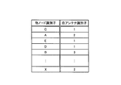
アンテナ情報記憶部4bは、一のアンテナ1を識別する情報である自アンテナ識別子、及び当該一のアンテナ1に電波が受信され、アンテナ選択部2aにより選択された他ノード12を識別する情報である他ノード識別子を対応付けて格納する。
例えば、アンテナ情報記憶部4bは、図3に示すように、複数の他ノード12にそれぞれ割り振られた識別子(A、B、C、・・・)と、複数のアンテナ1にそれぞれ割り振られた識別子(1、2、3、・・・)とをそれぞれ対応付け、アンテナ情報として、アンテナ情報管理テーブルに保持するものである。
経路情報記憶部4cは、他ノード12毎の次の経路先ノード(経路として設定している他ノード12)の経路情報を記憶しておくルート管理テーブルを保持しており、このルート管理テーブルに、通信相手の他ノード12と通信する場合に要する中継回数(ホップ数)や、直近の経路先となる他ノード12の情報などを記録している。
なお、アドホックネットワーク101を構成する各ノード10(無線通信装置11、他ノード12)は、定期的に他のノード10に対して信号を送信し、他のノード10から応答がない場合に、応答がなかったノード10に対して、図示しない統合監視サーバーにより、生存確認を行なう。そして、無線通信装置11は、応答がなかった他ノード12の情報を、アンテナ情報管理テーブル及びルート管理テーブルから削除する。
経路決定部4aは、ドライバ部3を介して入力されたデータに基づき、経路制御パケットから情報を取り出して処理し、経路情報記憶部4cに経路情報を記録すると共に、対応する自アンテナ識別子及び他ノード識別子をアンテナ情報記憶部4bに記録する。すなわち、経路決定部4aは、アンテナ選択部2aにより選択された一のアンテナ1により電波が受信された他ノード12と、当該一のアンテナ1と、を対応付けるアンテナ情報対応付部としての機能を有する。
なお、経路決定部4aは、同一の他ノード12から電波を複数回受信した場合に、アンテナ情報記憶部4bにおける、当該他ノード12に対応する既に記録されている自アンテナ識別子に対して、最新の自アンテナ識別子を上書きするものである。
また、経路決定部4aは、データ処理部5にデータを出力し、データ処理部5から処理データが入力されると、経路情報記憶部4cのルート管理テーブルを参照して、送信先の他ノード12を決定する。
使用アンテナ決定部4dは、経路決定部4aから処理データが入力されると、アンテナ情報記憶部4bのアンテナ情報管理テーブルを参照して、送信先の他ノード12に対応するアンテナ1の自アンテナ識別子を抽出して、ドライバ部3に出力する。
つぎに、本実施形態に係る無線通信装置11による処理手順について、図4を用いて説明する。まず、各アンテナ1は、他ノード12からの電波を受信し(ステップS1)、アンテナ選択部2aに出力する。
アンテナ選択部2aは、各アンテナ1における電波強度を比較し(ステップS2)、電波強度の値が最大値である一のアンテナ1を選択する(ステップS3)。そして、アンテナ選択部2aは、選択したアンテナ1が受信した無線信号及び当該アンテナ1の自アンテナ識別子を受信部2bに出力する(ステップS4)。
受信部2bは、アンテナ選択部2aから入力された無線信号を復調処理して(ステップS5)、物理層のデータに変換し、ドライバ部3を介して、経路決定部4aに出力する。
経路決定部4aは、経路制御パケットから情報を取り出して処理し、経路情報記憶部4cに経路情報を記録すると共に、自アンテナ識別子及び他ノード識別子を対応付けたアンテナ情報をアンテナ情報記憶部4bに記録する(ステップS6)。
また、経路決定部4aは、データ処理部5にデータを出力し、データ処理部5は、当該データに対して、所定の処理を行ない(ステップS7)、経路決定部4aに処理データを出力する。
そして、経路決定部4aは、データ処理部5からの処理データが入力されると、経路情報記憶部4cのルート管理テーブルを参照し(ステップS8)、送信先の他ノード12(ここでは、当該データの基である電波を送信した他ノード12)を決定して(ステップS9)、送信先の情報(他ノード識別子を含む)及び処理データを使用アンテナ決定部4dに出力する。
そして、使用アンテナ決定部4dは、データ処理部5からの送信先の情報及び処理データが入力されると、アンテナ情報記憶部4bのアンテナ情報管理テーブルを参照する(ステップS10)。
そして、使用アンテナ決定部4dは、送信先の他ノード識別子に基づき、該当する自アンテナ識別子を抽出して、送信先に対して電波を送信するために使用するアンテナを決定し(ステップS11)、ドライバ部3を介して、自アンテナ識別子、送信先の情報及び処理データを送信部2cに出力する(ステップS12)。
送信部2cは、ドライバ部3から入力された送信先の情報及び処理データに対して、物理層として必要な信号処理及び変調処理を行ない(ステップS13)、無線信号に乗せて、自アンテナ識別子と共に、アンテナ選択部2aに出力する。
アンテナ選択部2aは、送信部2cから入力された自アンテナ識別子に基づき、当該自アンテナ識別子に対応するアンテナ1を選択し(ステップS14)、当該アンテナ1に無線信号を出力する。アンテナ1は、入力された無線信号を該当する他ノード12に対して送信する(ステップS15)。
以上のように、本実施形態に係る無線通信装置11においては、他ノード12からの電波を受信し選択したアンテナ1の自アンテナ識別子と当該他ノード12の他ノード識別子とを、他ノード12毎に対応付けて記憶し、他ノード12への送信時に使用するアンテナの選択に、このアンテナ情報(自アンテナ識別子、他ノード識別子)を使用する。これにより、無線通信装置11は、他ノード12からの電波を受信し選択したアンテナ1(受信時点で無線品質が最も良いアンテナ1)と同一のアンテナ1を使用して、当該他ノード12に電波を送信することができ、無線品質の良い通信を行なうことができるという作用効果を奏する。
また、本実施形態に係る無線通信装置11においては、無線品質の向上により、他ノード12への送信の失敗を抑制することができ、他ノード12への送信に失敗したアンテナ1に換えて他のアンテナ1を使用することによる再送などの通信トラフィックの低減を図ることができるという作用効果を奏する。
(本発明の第2の実施形態)
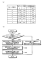
図5(a)は図2に示すアンテナ情報記憶部に記録されるアンテナ情報の他の例を示す説明図、図5(b)は図4に示すフローチャートのステップS11の詳細な内容を示すフローチャートである。図5において、図1~図4と同じ符号は、同一又は相当部分を示し、その説明を省略する。
図5(a)は図2に示すアンテナ情報記憶部に記録されるアンテナ情報の他の例を示す説明図、図5(b)は図4に示すフローチャートのステップS11の詳細な内容を示すフローチャートである。図5において、図1~図4と同じ符号は、同一又は相当部分を示し、その説明を省略する。
本実施形態に係る無線通信装置11においては、経路決定部4aが対応付ける他ノード識別子及び自アンテナ識別子を、順次、アンテナ情報記憶部4bに格納し、アンテナ情報記憶部4bがバッファとして機能して、自アンテナ識別子が所定の数に達するまで保持する。これに対し、前述した第1の実施形態に係る無線通信装置11においては、経路決定部4aが、同一の他ノード12から電波を複数回受信した場合に、アンテナ情報記憶部4bにおける、当該他ノード12に対応する既に記録されている自アンテナ識別子に対して、最新の自アンテナ識別子を上書きするものである。
アンテナ情報記憶部4bは、例えば、図5(a)に示すように、他ノード識別子毎に、複数(ここでは、n個であり、nは1以上の自然数)の自アンテナ識別子を対応付けて格納する。
使用アンテナ決定部4dは、送信先の他ノード12の他ノード識別子に対応する自アンテナ識別子のうち、最新の自アンテナ識別子と当該最新の自アンテナ識別子から過去に記録された所定の数(ここでは、k個(k<=n))までの自アンテナ識別子とを対象にする統計により、当該自アンテナ識別子毎の出現頻度を演算し、当該出現頻度が最大となる自アンテナ識別子に基づき、当該送信先の他ノード12に使用するアンテナ1を決定する。
なお、ここでの統計による処理として、アンテナ情報記憶部4bにおける、最新の自アンテナ識別子の重要度(重み付け)を高くし、1つ過去に遡る毎に、自アンテナ識別子の重要度を徐々に低くしたうえで、各自アンテナ識別子の出現頻度を演算することが考えられる。
また、他の統計処理としては、最新の自アンテナ識別子の記録により、同一の自アンテナ識別子が連続して記録された場合に、当該最新の自アンテナ識別子の出現頻度を最大とすることが考えられる。
つぎに、本実施形態に係る無線通信装置11による処理手順のうち、本実施形態の特徴である、前述した統計処理を考慮したステップ(図4のステップS11に相当)についてのみ、図5(b)を用いて説明する。
まず、使用アンテナ決定部4dは、他ノード識別子に基づき、該当する自アンテナ識別子のうち、最新の自アンテナ識別子と当該最新の自アンテナ識別子の1つ前に記録された自アンテナ識別子とを比較し、一致(連続)しているか否かを判定する(ステップS101)。
ステップS101において、一致(連続)していると判断した場合には(ステップS101、Yes)、使用アンテナ決定部4dは、該当する自アンテナ識別子のうち、最新の自アンテナ識別子を抽出し(ステップS102)、送信先に対して電波を送信するために使用するアンテナを決定する。
また、ステップS101において、一致(連続)していないと判断した場合には(ステップS101、No)、使用アンテナ決定部4dは、該当する自アンテナ識別子のうち、最新の自アンテナ識別子と当該最新の自アンテナ識別子から過去に記録された所定の数までの自アンテナ識別子とを対象にして、各自アンテナ識別子に重み付けを行なう(ステップS103)。
そして、使用アンテナ決定部4dは、該当する自アンテナ識別子のうち、最新の自アンテナ識別子と当該最新の自アンテナ識別子から過去に記録された所定の数までの自アンテナ識別子に対して、自アンテナ識別子毎の出現頻度を演算する(ステップS104)。
そして、使用アンテナ決定部4dは、出現頻度が最大である自アンテナ識別子を抽出し(ステップS105)、送信先に対して電波を送信するために使用するアンテナを決定する。
なお、この第2の実施形態に係る無線通信装置11においては、他ノード識別子毎に複数の自アンテナ識別子を対応付けて格納し、当該複数の自アンテナ識別子に基づき、使用アンテナを決定するところのみが第1の実施形態と異なるところであり、複数の自アンテナ識別子を判断材料とすることによる作用効果以外は、第1の実施形態と同様の作用効果を奏する。
本実施形態においては、複数の自アンテナ識別子に基づき、送信先に対して電波を送信するために使用するアンテナ1を決定することで、第1の実施形態と比較して、電波状態の揺らぎによるアンテナ選択の影響を抑制することができ、より有効なアンテナ1を選択することができるという作用効果を奏する。
(本発明の第3の実施形態)
図6(a)は図2に示すアンテナ情報記憶部に記録されるアンテナ情報の他の例を示す説明図、図6(b)は図4に示すフローチャートのステップS11の詳細な内容を示すフローチャートである。図6において、図1~図5と同じ符号は、同一又は相当部分を示し、その説明を省略する。
図6(a)は図2に示すアンテナ情報記憶部に記録されるアンテナ情報の他の例を示す説明図、図6(b)は図4に示すフローチャートのステップS11の詳細な内容を示すフローチャートである。図6において、図1~図5と同じ符号は、同一又は相当部分を示し、その説明を省略する。
前述した第2の実施形態においては、アンテナ情報記憶部4bがバッファとして機能し、自アンテナ識別子が所定の数に達するまで保持していたが、本実施形態においては、各自アンテナ識別子と共に、各アンテナ1による電波受信時の電波強度(以下、受信電波強度と称す)も保持する。
アンテナ情報記憶部4bは、例えば、図6(a)に示すように、他ノード識別子毎に、複数(ここでは、n個であり、nは1以上の自然数)の自アンテナ識別子と、当該自アンテナ識別子に対応する受信電波強度とを対応付けて格納する。
使用アンテナ決定部4dは、送信先の他ノード12の他ノード識別子に対応し、自アンテナ識別子に対応する受信電波強度のうち、最新の自アンテナ識別子に対応する受信電波強度と当該最新の自アンテナ識別子から過去に記録された所定の数(ここでは、k個(k<=n))までの自アンテナ識別子に対応する受信電波強度とを対象にする統計により、当該自アンテナ識別子毎の受信電波強度を演算し、当該受信電波強度が最大となる自アンテナ識別子に基づき、当該送信先の他ノード12に使用するアンテナ1を決定する。
なお、ここでの統計による処理として、アンテナ情報記憶部4bにおける、最新の自アンテナ識別子に対応する受信電波強度の重要度(重み付け)を高くし、1つ過去に遡る毎に、自アンテナ識別子に対応する受信電波強度の重要度を徐々に低くしたうえで、各自アンテナ識別子の受信電波強度を演算することが考えられる。
つぎに、本実施形態に係る無線通信装置11による処理手順のうち、本実施形態の特徴である、前述した統計処理を考慮したステップ(図4のステップS11に相当)についてのみ、図6(b)を用いて説明する。
まず、使用アンテナ決定部4dは、他ノード識別子に基づき、該当する自アンテナ識別子のうち、最新の自アンテナ識別子と当該最新の自アンテナ識別子の1つ前に記録された自アンテナ識別子とを比較し、一致(連続)しているか否かを判定する(ステップS201)。
ステップS201において、一致(連続)していると判断した場合には(ステップS201、Yes)、使用アンテナ決定部4dは、該当する自アンテナ識別子のうち、最新の自アンテナ識別子を抽出し(ステップS202)、送信先に対して電波を送信するために使用するアンテナ1を決定する。
また、ステップS201において、一致(連続)していないと判断した場合には(ステップS201、No)、使用アンテナ決定部4dは、該当する自アンテナ識別子に対応する受信電波強度のうち、最新の自アンテナ識別子に対応する受信電波強度と当該最新の自アンテナ識別子から過去に記録された所定の数までの自アンテナ識別子に対応する受信電波強度とを対象にして、各自アンテナ識別子に対応する受信電波強度に重み付けを行なう(ステップS203)。
そして、使用アンテナ決定部4dは、該当する自アンテナ識別子に対応する受信電波強度のうち、最新の自アンテナ識別子に対応する受信電波強度と当該最新の自アンテナ識別子から過去に記録された所定の数までの自アンテナ識別子に対応する受信電波強度に対して、自アンテナ識別子毎の受信電波強度を演算する(ステップS204)。
そして、使用アンテナ決定部4dは、受信電波強度が最大である自アンテナ識別子を抽出し(ステップS205)、送信先に対して電波を送信するために使用するアンテナ1を決定する。
なお、この第3の実施形態に係る無線通信装置11においては、他ノード識別子毎に複数の自アンテナ識別子と当該自アンテナ識別子に対応する受信電波強度とを対応付けて格納し、当該受信電波強度に基づき、使用するアンテナ1を決定するところのみが第2の実施形態と異なるところであり、受信電波強度を判断材料とすることによる作用効果以外は、第1の実施形態及び第2の実施形態と同様の作用効果を奏する。
本実施形態においては、各アンテナ1による電波受信時の電波強度に基づき、送信先に対して電波を送信するために使用するアンテナ1を決定することで、第2の実施形態と比較して、受信する電波強度が安定したアンテナ1の選択を行なうことができるという作用効果を奏する。
なお、第2の実施形態は、自アンテナ識別子毎の出現頻度を考慮し、第3の実施形態は、自アンテナ識別子毎の受信電波強度を考慮して、それぞれの判断材料に基づき、使用するアンテナ1を決定しているが、これらの判断材料を併用して、使用アンテナ1を決定してもよい。
すなわち、図5(b)のステップS105において、出現頻度が最大である自アンテナ識別子が複数存在する場合に、受信電波強度を判断材料として、使用するアンテナ1を一つに絞り込むことが考えられる。同様に、図6(b)のステップS205において、受信電波強度が最大である自アンテナ識別子が複数存在する場合に、出現頻度を判断材料として、使用するアンテナ1を一つに絞り込むことが考えられる。
1 アンテナ
2 無線モジュール
2a アンテナ選択部
2b 受信部
2c 送信部
3 ドライバ部
4 プロトコル処理部4a 経路決定部
4b アンテナ情報記憶部
4c 経路情報記憶部
4d 使用アンテナ決定部
5 データ処理部
10 ノード
11 無線通信装置
12 他ノード
100 無線アドホック通信システム
101 アドホックネットワーク
102 ゲートウェイ
103 サーバー
2 無線モジュール
2a アンテナ選択部
2b 受信部
2c 送信部
3 ドライバ部
4 プロトコル処理部4a 経路決定部
4b アンテナ情報記憶部
4c 経路情報記憶部
4d 使用アンテナ決定部
5 データ処理部
10 ノード
11 無線通信装置
12 他ノード
100 無線アドホック通信システム
101 アドホックネットワーク
102 ゲートウェイ
103 サーバー
Claims (5)
- アドホックネットワークを構成する複数のノードのうち、一のノードである無線通信装置において、
他のノードとの間で電波を送受信する複数のアンテナと、
前記他のノードからの電波を受信したアンテナのうち、電波強度に応じて一のアンテナを選択するアンテナ選択部と、
前記アンテナ選択部により選択された一のアンテナにより電波が受信された前記他のノードと当該一のアンテナとを対応付けるアンテナ情報対応付部と、
前記アンテナ情報対応付部により対応付けられた他のノード及びアンテナの情報に基づき、他のノードに電波を送信するアンテナを決定する使用アンテナ決定部と、
を備えている無線通信装置。 - 前記請求項1に記載の無線通信装置において、
前記アンテナ情報対応付部が、他のノードからの電波を受信する度に、前記他のノードと前記一のアンテナとを対応付ける無線通信装置。 - 前記請求項1に記載の無線通信装置において、
前記使用アンテナ決定部が、前記アンテナ情報対応付部により対応付けられた他のノード及びアンテナの情報に基づき、当該他のノードからの電波を受信した各アンテナの出現頻度を演算し、当該出現頻度に基づき、前記送信するアンテナを決定する無線通信装置。 - 前記請求項1乃至3のいずれかに記載の無線通信装置において、
前記アンテナ情報対応付部が、前記アンテナの電波受信時における電波強度の値を、当該アンテナに対応付け、
前記使用アンテナ決定部が、前記アンテナ情報対応付部により対応付けられた他のノード、アンテナ及び電波強度の情報に基づき、前記送信するアンテナを決定する無線通信装置。 - アドホックネットワークを構成する複数のノードのうち、他のノードとの間で電波を送受信する複数のアンテナを備えた一のノードによる無線通信方法において、
前記他のノードからの電波を受信したアンテナのうち、電波強度に応じて一のアンテナを選択するアンテナ選択ステップと、
前記アンテナ選択ステップにより選択された一のアンテナにより電波が受信された前記他のノードと当該一のアンテナとを対応付けるアンテナ情報対応付ステップと、
前記アンテナ情報対応付ステップにより対応付けられた他のノード及びアンテナの情報に基づき、他のノードに電波を送信するアンテナを決定する使用アンテナ決定ステップと、
を含む無線通信方法。
Applications Claiming Priority (2)
| Application Number | Priority Date | Filing Date | Title |
|---|---|---|---|
| JP2008-268827 | 2008-10-17 | ||
| JP2008268827A JP4935794B2 (ja) | 2008-10-17 | 2008-10-17 | 無線通信装置及び無線通信方法 |
Publications (1)
| Publication Number | Publication Date |
|---|---|
| WO2010044293A1 true WO2010044293A1 (ja) | 2010-04-22 |
Family
ID=42106460
Family Applications (1)
| Application Number | Title | Priority Date | Filing Date |
|---|---|---|---|
| PCT/JP2009/062472 Ceased WO2010044293A1 (ja) | 2008-10-17 | 2009-07-08 | 無線通信装置及び無線通信方法 |
Country Status (2)
| Country | Link |
|---|---|
| JP (1) | JP4935794B2 (ja) |
| WO (1) | WO2010044293A1 (ja) |
Cited By (4)
| Publication number | Priority date | Publication date | Assignee | Title |
|---|---|---|---|---|
| JP2017084376A (ja) * | 2012-03-21 | 2017-05-18 | パワーキャスト コーポレイションPowercast Corporation | スイッチ及びアウトレット制御を備えたワイヤレス・センサ・システム、方法、及び装置 |
| US10455663B2 (en) | 2013-10-23 | 2019-10-22 | Powercast Corporation | Automated system for lighting control |
| US10524337B2 (en) | 2015-05-04 | 2019-12-31 | Powercast Corporation | Automated system for lighting control |
| US10979961B2 (en) | 2016-10-07 | 2021-04-13 | Powercast Corporation | Automated system for lighting control |
Families Citing this family (3)
| Publication number | Priority date | Publication date | Assignee | Title |
|---|---|---|---|---|
| WO2013054415A1 (ja) * | 2011-10-13 | 2013-04-18 | 三菱電機株式会社 | 無線端末装置および無線通信システム |
| JP6121935B2 (ja) * | 2014-03-28 | 2017-04-26 | ソフトバンク株式会社 | 基地局制御装置及びプログラム |
| JP6331947B2 (ja) * | 2014-10-09 | 2018-05-30 | トヨタ自動車株式会社 | 無線通信装置および通信方法 |
Citations (6)
| Publication number | Priority date | Publication date | Assignee | Title |
|---|---|---|---|---|
| JPH10276124A (ja) * | 1997-03-28 | 1998-10-13 | Hitachi Ltd | 無線通信網 |
| WO2000016499A1 (en) * | 1998-09-11 | 2000-03-23 | Matsushita Electric Industrial Co., Ltd. | Method of directive transmission and directivity-controlled communication device |
| JP2000138624A (ja) * | 1998-10-29 | 2000-05-16 | Matsushita Electric Ind Co Ltd | 無線通信装置及び送信アンテナ切替方法 |
| JP2001007747A (ja) * | 1999-06-24 | 2001-01-12 | Kdd Corp | 伝送路選択方法および装置 |
| JP2007306341A (ja) * | 2006-05-11 | 2007-11-22 | Toyota Industries Corp | アンテナ切替え方法および無線通信装置 |
| JP2008061080A (ja) * | 2006-09-01 | 2008-03-13 | Alpine Electronics Inc | 車載用通信装置及びアンテナ切替方法 |
Family Cites Families (5)
| Publication number | Priority date | Publication date | Assignee | Title |
|---|---|---|---|---|
| JP2005064671A (ja) * | 2003-08-08 | 2005-03-10 | Advanced Telecommunication Research Institute International | 無線ネットワークのための制御方法及び制御装置 |
| JP2005303903A (ja) * | 2004-04-15 | 2005-10-27 | Advanced Telecommunication Research Institute International | 無線装置、それを備えた無線通信システム、および無線通信方法 |
| JP2005323219A (ja) * | 2004-05-11 | 2005-11-17 | Oki Electric Ind Co Ltd | 無線通信装置及び無線通信ネットワークシステム |
| JP2006166314A (ja) * | 2004-12-10 | 2006-06-22 | Advanced Telecommunication Research Institute International | 無線局位置推定装置及び方法 |
| WO2006137259A1 (ja) * | 2005-06-21 | 2006-12-28 | Pioneer Corporation | 受信装置 |
-
2008
- 2008-10-17 JP JP2008268827A patent/JP4935794B2/ja not_active Expired - Fee Related
-
2009
- 2009-07-08 WO PCT/JP2009/062472 patent/WO2010044293A1/ja not_active Ceased
Patent Citations (6)
| Publication number | Priority date | Publication date | Assignee | Title |
|---|---|---|---|---|
| JPH10276124A (ja) * | 1997-03-28 | 1998-10-13 | Hitachi Ltd | 無線通信網 |
| WO2000016499A1 (en) * | 1998-09-11 | 2000-03-23 | Matsushita Electric Industrial Co., Ltd. | Method of directive transmission and directivity-controlled communication device |
| JP2000138624A (ja) * | 1998-10-29 | 2000-05-16 | Matsushita Electric Ind Co Ltd | 無線通信装置及び送信アンテナ切替方法 |
| JP2001007747A (ja) * | 1999-06-24 | 2001-01-12 | Kdd Corp | 伝送路選択方法および装置 |
| JP2007306341A (ja) * | 2006-05-11 | 2007-11-22 | Toyota Industries Corp | アンテナ切替え方法および無線通信装置 |
| JP2008061080A (ja) * | 2006-09-01 | 2008-03-13 | Alpine Electronics Inc | 車載用通信装置及びアンテナ切替方法 |
Cited By (11)
| Publication number | Priority date | Publication date | Assignee | Title |
|---|---|---|---|---|
| JP2017084376A (ja) * | 2012-03-21 | 2017-05-18 | パワーキャスト コーポレイションPowercast Corporation | スイッチ及びアウトレット制御を備えたワイヤレス・センサ・システム、方法、及び装置 |
| US10638399B2 (en) | 2012-03-21 | 2020-04-28 | Powercast Corporation | Wireless sensor system, method and apparatus with switch and outlet control |
| US11457395B2 (en) | 2012-03-21 | 2022-09-27 | Powercast Corporation | Wireless sensor system, method and apparatus with switch and outlet control |
| US11917519B2 (en) | 2012-03-21 | 2024-02-27 | Powercast Corporation | Wireless sensor system, method and apparatus with switch and outlet control |
| US12369095B2 (en) | 2012-03-21 | 2025-07-22 | Powercast Corporation | Wireless sensor system, method and apparatus with switch and outlet control |
| US10455663B2 (en) | 2013-10-23 | 2019-10-22 | Powercast Corporation | Automated system for lighting control |
| US11102869B2 (en) | 2013-10-23 | 2021-08-24 | Powercast Corporation | Automated system for lighting control |
| US10524337B2 (en) | 2015-05-04 | 2019-12-31 | Powercast Corporation | Automated system for lighting control |
| US11039524B2 (en) | 2015-05-04 | 2021-06-15 | Powercast Corporation | Automated system for lighting control |
| US10979961B2 (en) | 2016-10-07 | 2021-04-13 | Powercast Corporation | Automated system for lighting control |
| US11696211B2 (en) | 2016-10-07 | 2023-07-04 | Powercast Corporation | Automated system for lighting control |
Also Published As
| Publication number | Publication date |
|---|---|
| JP2010098595A (ja) | 2010-04-30 |
| JP4935794B2 (ja) | 2012-05-23 |
Similar Documents
| Publication | Publication Date | Title |
|---|---|---|
| CN111543080B (zh) | 用于网络拓扑管理的系统和方法 | |
| JP4935794B2 (ja) | 無線通信装置及び無線通信方法 | |
| KR101150011B1 (ko) | 가중된 누적형 예상 전송 시간 메트릭을 사용하는 링크품질 라우팅을 위한 시스템 및 방법 | |
| US7948891B2 (en) | Wireless communication apparatus, communication routing control apparatus, communication routing control method and communication system | |
| US20070201427A1 (en) | Apparatus and method for setting multi-path | |
| JP2006518957A (ja) | 無線ネットワークにおける干渉ベースのルーティング | |
| JP3766346B2 (ja) | データリンク伝送制御方法、移動通信システム及びデータリンク伝送制御装置 | |
| CN109302731B (zh) | 无线网络系统与无线网络连线方法 | |
| JP5942329B2 (ja) | 通信方法およびシステム、アクセスネットワーク装置、端末、およびコアネットワーク装置 | |
| JP5725173B2 (ja) | 無線局、ルーティング方法、無線通信システムおよびルーティング用プログラム | |
| TW200845782A (en) | Wireless radio and a handover method of the wireless radio | |
| KR20170056547A (ko) | 다수의 채널들을 통한 데이터 링크 그룹의 루트 형성 및 메시지 송신 | |
| EP3229528B1 (en) | Method, device and system for establishing on-demand route | |
| JP5086176B2 (ja) | 携帯通信端末および無線通信方法 | |
| US9137145B2 (en) | Communication method of hub and transmitting, receiving terminal included in virtual group | |
| US10506510B2 (en) | Method for increasing lifetime of network devices in a multi-hop structured wireless communication system | |
| JP2013207687A (ja) | 通信局、通信制御プログラム及び通信ネットワークシステム | |
| EP3051919B1 (en) | Device and method for wireless communication used in wireless ad hoc network | |
| JP5326977B2 (ja) | 変更通知方法、変更通知装置ならびにプログラム | |
| JP2005287074A (ja) | データリンク伝送制御方法、移動通信システム、基地局、移動局、移動局制御プログラム及びコンピュータ読み取り可能な記録媒体 | |
| JP4344341B2 (ja) | データリンク伝送制御方法、移動通信システム及びデータリンク伝送制御装置 | |
| JP2012015733A (ja) | 通信端末、経路選択方法及び通信方式 | |
| CN115396974B (zh) | 回传链路的数据转发方法、配置方法及设备 | |
| US20140064085A1 (en) | Communication node and communication method | |
| JP4851511B2 (ja) | ルーティング方法並びに前記方法を実行するトランシーバ基地局及びコンピュータプログラム |
Legal Events
| Date | Code | Title | Description |
|---|---|---|---|
| 121 | Ep: the epo has been informed by wipo that ep was designated in this application |
Ref document number: 09820471 Country of ref document: EP Kind code of ref document: A1 |
|
| NENP | Non-entry into the national phase |
Ref country code: DE |
|
| 122 | Ep: pct application non-entry in european phase |
Ref document number: 09820471 Country of ref document: EP Kind code of ref document: A1 |