WO2010044196A1 - 撮影用光学装置 - Google Patents
撮影用光学装置 Download PDFInfo
- Publication number
- WO2010044196A1 WO2010044196A1 PCT/JP2009/004803 JP2009004803W WO2010044196A1 WO 2010044196 A1 WO2010044196 A1 WO 2010044196A1 JP 2009004803 W JP2009004803 W JP 2009004803W WO 2010044196 A1 WO2010044196 A1 WO 2010044196A1
- Authority
- WO
- WIPO (PCT)
- Prior art keywords
- coil
- driving
- drive
- case body
- lens
- Prior art date
- Legal status (The legal status is an assumption and is not a legal conclusion. Google has not performed a legal analysis and makes no representation as to the accuracy of the status listed.)
- Ceased
Links
Images



Classifications
-
- G—PHYSICS
- G03—PHOTOGRAPHY; CINEMATOGRAPHY; ANALOGOUS TECHNIQUES USING WAVES OTHER THAN OPTICAL WAVES; ELECTROGRAPHY; HOLOGRAPHY
- G03B—APPARATUS OR ARRANGEMENTS FOR TAKING PHOTOGRAPHS OR FOR PROJECTING OR VIEWING THEM; APPARATUS OR ARRANGEMENTS EMPLOYING ANALOGOUS TECHNIQUES USING WAVES OTHER THAN OPTICAL WAVES; ACCESSORIES THEREFOR
- G03B5/00—Adjustment of optical system relative to image or object surface other than for focusing
-
- G—PHYSICS
- G02—OPTICS
- G02B—OPTICAL ELEMENTS, SYSTEMS OR APPARATUS
- G02B27/00—Optical systems or apparatus not provided for by any of the groups G02B1/00 - G02B26/00, G02B30/00
- G02B27/64—Imaging systems using optical elements for stabilisation of the lateral and angular position of the image
- G02B27/646—Imaging systems using optical elements for stabilisation of the lateral and angular position of the image compensating for small deviations, e.g. due to vibration or shake
-
- G—PHYSICS
- G03—PHOTOGRAPHY; CINEMATOGRAPHY; ANALOGOUS TECHNIQUES USING WAVES OTHER THAN OPTICAL WAVES; ELECTROGRAPHY; HOLOGRAPHY
- G03B—APPARATUS OR ARRANGEMENTS FOR TAKING PHOTOGRAPHS OR FOR PROJECTING OR VIEWING THEM; APPARATUS OR ARRANGEMENTS EMPLOYING ANALOGOUS TECHNIQUES USING WAVES OTHER THAN OPTICAL WAVES; ACCESSORIES THEREFOR
- G03B2205/00—Adjustment of optical system relative to image or object surface other than for focusing
- G03B2205/0007—Movement of one or more optical elements for control of motion blur
- G03B2205/0023—Movement of one or more optical elements for control of motion blur by tilting or inclining one or more optical elements with respect to the optical axis
Definitions
- the present invention relates to a photographic optical device having a shake correction function for correcting a shake by swinging a lens driving device on which a lens and an image sensor are mounted.
- the optical device described in Patent Document 1 is fixed to a movable portion on which a lens and an image sensor are mounted, a pivot shaft that is fixed to the base of the optical device and contacts the bottom surface of the movable portion, and a base.
- a leaf spring for swingably supporting the movable part and a swinging mechanism for swinging the movable part are provided.
- the camera shake is corrected by the movable portion swinging about the pivot shaft by the driving force of the swing mechanism.
- the swing mechanism is constituted by a drive coil and a drive magnet.
- an object of the present invention is to provide a photographing optical device capable of obtaining a sufficient driving force for swinging a lens driving device on which a lens and an image sensor are mounted.
- a first imaging optical device includes a lens driving device including a lens, an imaging element, and a lens driving mechanism for driving the lens, and changes in the tilt of the lens driving device.
- the swing drive mechanism includes a drive coil and a drive magnet, and a coil mounting member to which the drive coil is attached has a recess or an opening for arranging the drive coil. It is characterized by.
- the coil attachment member to which the drive coil constituting the swing drive mechanism is attached has a recess or an opening for arranging the drive coil. Therefore, the number of turns of the driving coil can be increased by the amount corresponding to the recess of the recess or the thickness of the coil mounting member. Therefore, in the present invention, the driving force of the swing drive mechanism can be improved, and a sufficient drive force for swinging the lens driving device can be obtained.
- the coil attachment member is, for example, a case body that constitutes the outer peripheral surface of the photographing optical device.
- the case body it is preferable that an opening is formed in the case body. If comprised in this way, compared with the case where the recessed part is formed in the case body, the number of turns of the drive coil can be increased.
- the photographing optical device includes a resin coil holder that holds the driving coil, and the driving coil is attached to the opening via the coil holder. If comprised in this way, it will become possible to form a case body with a metal material, for example. That is, it is possible to form the case body from a relatively rigid metal material. Therefore, it is possible to appropriately protect each component disposed inside the case body.
- the driving coil and the coil holder are preferably integrally molded. If comprised in this way, the fixation strength of the drive coil with respect to a coil holder can be raised, and it will become possible to prevent the drive coil from coming off from the coil holder.
- the coil holder is formed with a stepped portion that fits into the opening, and the driving coil is positioned with respect to the case body by fitting the stepped portion into the opening.
- the step portion includes a small diameter portion that abuts on the edge of the opening, and a large diameter portion that expands from the small diameter portion, and includes an outer peripheral surface of the small diameter portion, an outer peripheral surface of the small diameter portion, and an outer peripheral surface of the large diameter portion.
- a step portion is formed by the surface connecting the outer peripheral surface of the small diameter portion, the outer peripheral surface of the small diameter portion abuts on the edge of the opening, and the surface connecting the outer peripheral surface of the small diameter portion and the outer peripheral surface of the large diameter portion is the inside of the case body.
- the case body is preferably formed of a metal material having conductivity. If comprised in this way, it will become possible to make the whole imaging
- the drive coil is attached to the opening of the case body via a resin coil holder, not only can the drive coil be prevented from being damaged or disconnected due to contact with the case body, but the drive coil can also be driven. There is no short circuit of the coil.
- a second imaging optical device includes a lens driving device including a lens, an imaging element, and a lens driving mechanism for driving the lens, and a sensor for detecting a change in the tilt of the lens driving device.
- a shake correction mechanism that corrects shake by swinging the lens drive device based on the detection result of the sensor, and the shake correction mechanism includes a swing drive mechanism that swings the lens drive device,
- the mechanism includes a driving coil and a driving magnet that are arranged to face each other.
- the driving coil includes a winding portion formed by winding a conductive wire in the circumferential direction, and a winding start portion or winding of the driving coil.
- the lead portion is formed by being drawn from the inner peripheral side toward the outer peripheral side so that the end portion intersects the winding portion. of Wherein the parts or openings are formed.
- the coil attachment member to which the drive coil is attached is provided with a recess or an opening for arranging a lead portion formed on the drive coil. Therefore, the lead portion is disposed on the surface of the drive coil opposite to the surface facing the drive magnet (that is, the attachment surface to the coil mounting member), and the lead portion is disposed in the recess or the opening. In the state, the drive coil can be attached to the coil attachment member.
- the drawing part arranged in the recess or the opening part It is possible to increase the number of turns of the drive coil by increasing the thickness of the drive coil by the thickness, and the opposite surface of the drive coil to the drive magnet and the opposite surface of the drive magnet to the drive coil This makes it possible to reduce the gap.
- the present invention it becomes possible to improve the driving force of the swing drive mechanism, and even when the photographic optical device is reduced in size and thickness, it is sufficient to swing the lens drive device. It becomes possible to obtain a sufficient driving force.
- the coil mounting member is a case body that constitutes the outer peripheral surface of the imaging optical device, and the drive coil has a surface on the side where the lead wire is disposed facing the inner peripheral surface of the case body.
- the drive coil has a surface on the side where the lead wire is disposed facing the inner peripheral surface of the case body.
- an opening is formed in the case body.
- a through hole serving as an opening may be formed on the side surface of the case body, so that the case body can be easily manufactured as compared with the case where the concave portion is formed on the inner peripheral surface of the case body. Become.
- the winding part is preferably formed in a rectangular shape composed of a long side part and a short side part, and the height of the opening is preferably larger than the height of the long side part.
- the conductive wire exposed at the opening is connected to the inside of the case body from the gap formed between the opening, that is, the edge of the opening and the lower portion of the long side of the driving coil. It can be pulled back to the circumferential side. Therefore, the conducting wire is not sandwiched between the winding portion of the driving coil and the edge of the opening, and disconnection or damage of the conducting wire can be avoided.
- the width of the opening is preferably narrower than the width of the long side. If comprised in this way, since an opening part should just be formed by the required minimum magnitude
- the first and second imaging optical devices it is possible to obtain a sufficient driving force for swinging the lens driving device on which the lens and the imaging element are mounted.
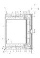
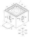
- FIG. 1 is a perspective view of a photographing optical device according to a first embodiment of the present invention.
- FIG. 2 is a cross-sectional view taken along a line EE in FIG. 1. It is a perspective view of the optical device for imaging
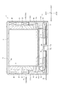
- FIG. 4 is a cross-sectional view taken along a line EE in FIG. 3. It is a figure for demonstrating the relationship between the coil for a drive shown in FIG. 3, and an opening part. It is a figure for demonstrating the connection state of the drive coil shown in FIG.
- FIG. 1 is a perspective view of a photographing optical apparatus 1 according to the first embodiment of the present invention.
- 2 is a cross-sectional view taken along the line EE of FIG.
- the three directions orthogonal to each other are defined as an X direction, a Y direction, and a Z direction.
- the X1 direction side is the “right” side
- the X2 direction side is the “left” side
- the Y1 direction side is the “front” side
- the Y2 direction side is the “rear (rear)” side
- the Z1 direction side is “up”.
- the “side” and the Z2 direction side are the “lower” side.
- the Z direction is the optical axis direction of the photographing optical device 1.
- the photographing optical device 1 of this embodiment is a small and thin camera mounted on a portable device such as a cellular phone, and is formed in a substantially rectangular parallelepiped shape as a whole.
- the photographing optical device 1 includes a lens driving device 2 equipped with a lens and an imaging element (not shown), and a sensor 4 for detecting a change in the tilt of the lens driving device 2. And a support 5 that supports the lens driving device 2 and a rocking drive mechanism 6 that rocks the lens driving device 2.
- the lens driving device 2 is equipped with a lens and an image sensor as described above. Specifically, a lens is mounted on the upper end side of the lens driving device 2, and an imaging element is mounted on the lower end of the lens driving device 2.
- the lens driving device 2 is equipped with a lens driving mechanism for driving the lens in the optical axis direction (vertical direction). This lens driving mechanism is constituted by, for example, a driving coil and a driving magnet.
- the lens driving device 2 is formed in a substantially rectangular parallelepiped shape as a whole.
- the front and rear and left and right side surfaces of the lens driving device 2 are covered with a cover member 9 formed in a substantially square cylindrical shape with a bottom having an open lower end.
- a circular through hole 9a is formed at the bottom of the cover member 9 disposed on the upper end side.
- a flange 9b is formed at the lower end of the cover member 9 so as to expand outward in the front-rear direction and outward in the left-right direction.
- Driving magnets 21 and 22, which will be described later, constituting the swing driving mechanism 6 are fixed to the front and rear and left and right side surfaces of the cover member 9, respectively.
- the cover member 9 of this embodiment is formed of a magnetic material.
- the sensor 4 is a gyroscope for detecting a change in the tilt of the lens driving device 2. That is, the sensor 4 is an angular velocity sensor for detecting the angular velocity of the lens driving device 2.
- the sensor 4 is disposed on the lower side of the lens driving device 2.
- a flexible printed circuit board (FPC) 10 is connected to the sensor 4.
- the FPC 10 is also connected to an image sensor mounted on the lens driving device 2.
- the FPC 10 is drawn on the lower end side of the photographing optical device 1 and pulled out from the left side surface of the photographing optical device 1.
- the senor 4 is arranged inside a sensor cover member 11 formed in a flat and substantially rectangular tube shape with a bottom having an upper end opened.
- a contact surface 11a with which a fulcrum protrusion 15b described later contacts is formed in a flat shape.
- a flange portion 11 b that comes into contact with the flange portion 9 b of the cover member 9 from below is formed so as to spread outward in the front-rear direction and outward in the left-right direction.
- the flange portion 9b and the flange portion 11b are fixed to each other. That is, the sensor cover member 11 is fixed to the lower end of the cover member 9.
- the lens driving device 2, the sensor 4, the cover member 9, and the sensor cover member 11 are supported by the support 5 so as to be swingable. That is, the lens driving device 2, the sensor 4, the cover member 9 and the sensor cover member 11 constitute a movable module 12 that can swing with respect to the support 5.
- the support body 5 includes a base body 15 constituting the lower surface of the photographing optical device 1 and case bodies 16 constituting the front and rear and left and right outer peripheral surfaces of the photographing optical device 1.
- a stopper member 18 for restricting the swing range of the movable module 12 is fixed to the case body 16.
- a leaf spring 17 is fixed to the stopper member 18 to support the movable module 12 in a swingable manner.
- the base body 15 is formed in a substantially rectangular shape.
- a projecting portion 15 a projecting upward is formed at the approximate center of the base body 15.
- a fulcrum protrusion 15b serving as a fulcrum for swinging the movable module 12 is formed on the upper surface of the protrusion 15a.
- the swinging fulcrum of the movable module 12 is disposed below the movable module 12.
- the fulcrum protrusion 15 b is formed in a hemispherical shape, for example, and is in contact with the contact surface 11 a of the sensor cover member 11.
- a fulcrum portion 19 serving as a center of oscillation of the lens driving device 2 is configured by the fulcrum protrusion 15b and the contact surface 11a.
- the case body 16 is formed in a substantially rectangular tube shape with an upper end and a lower end opened. On the front and rear side surfaces and the left and right side surfaces of the upper end side of the case body 16, openings 16 a for disposing drive coils 23 to be described later constituting the swing drive mechanism 6 are formed so as to penetrate the respective side surfaces. ing.
- the opening 16a is formed in a substantially rectangular shape.
- the case body 16 of this embodiment is formed of a nonmagnetic material.
- the case body 16 is formed of a conductive metal material.
- the case body 16a may be formed of a non-conductive metal material.
- the plate spring 17 is formed in a substantially rectangular shape as a whole.
- the four corners of the leaf spring 17 are fixed to the case body 16, and the movable module 12 (specifically, the sensor cover member 11) is fixed to the center portion of the leaf spring 17, and the leaf spring 17 is attached to the case body 16.
- a fixed portion that is fixed, a holding portion that holds the movable module 12, and a spring portion that connects the fixing portion and the holding portion are provided.
- the leaf spring 17 generates a pressurizing force to reliably contact the contact surface 11a of the sensor cover member 11 and the fulcrum protrusion 15b of the base body 15 (that is, the movable module 12 is moved downward). It is fixed to the case body 16 in a bent state so that a biasing force for biasing is generated. Further, the leaf spring 17 of this embodiment is specifically fixed to the case body 16 via a stopper member 18. That is, the four corners of the leaf spring 17 are fixed to the stopper member 18 fixed to the inner peripheral surface of the case body 16.
- the stopper member 18 is fixed to the inner peripheral surface of the lower end surface of the case body 16. Specifically, the stopper member 18 is fixed to the inner peripheral surface of the case body 16 at a position where it can contact the lower surface of the flange portion 11b of the sensor cover member 11, and the stopper member 18 and the flange portion 11b The swing range of the movable module 12 is restricted.
- the oscillating drive mechanism 6 includes drive magnets 21 and 22 and a drive coil 23 disposed opposite to the drive magnets 21 and 22.
- the swing mechanism 6 of this embodiment includes four drive magnets 21, four drive magnets 22, and four drive coils 23.
- the driving magnets 21 and 22 are formed in a substantially rectangular plate shape.
- the driving magnet 21 and the driving magnet 22 are formed to have the same width.
- the thickness of the drive magnet 21 and the thickness of the drive magnet 22 are different as will be described later.
- One drive magnet 21 and one drive magnet 22 are fixed to each of the front and rear side surfaces and the left and right side surfaces of the cover member 9. Specifically, the drive magnets 21 and 22 are fixed to the front and rear side surfaces and the left and right side surfaces of the cover member 9 with the lower surface of the drive magnet 21 and the upper surface of the drive magnet 22 in contact with each other. Yes.
- the cover member 9 is made of a magnetic material, and the cover member 9 functions as a back yoke for the drive magnets 21 and 22.
- the drive magnets 21 and 22 fixed to the left and right side surfaces of the cover member 9 are magnetized so that the magnetic poles formed on the right and left surfaces of the drive magnets 21 and 22 are different.
- the driving magnets 21 and 22 fixed to the left and right side surfaces of the cover member 9 have different magnetic poles formed on the outer surface of the driving magnet 21 and the outer surface of the driving magnet 22 in the left-right direction ( That is, the magnets are magnetized so that the magnetic poles formed on the inner surface of the driving magnet 21 and the inner surface of the driving magnet 22 in the left-right direction are different.
- the left and right outer surfaces of the driving magnet 21 fixed to the left and right side surfaces of the cover member 9 are magnetized to the N pole, and the left and right inner surfaces of the driving magnet 21 are magnetized to the S pole.
- the left and right outer surfaces of the drive magnet 22 fixed to the left and right side surfaces of the cover member 9 are magnetized to the S pole, and the left and right inner surfaces of the drive magnet 22 are magnetized to the N pole. Yes.
- the drive magnets 21 and 22 fixed to the front and rear side surfaces of the cover member 9 are magnetized so that the magnetic poles formed on the front and rear surfaces of the drive magnets 21 and 22 are different.
- the driving magnets 21 and 22 fixed to the front and rear side surfaces of the cover member 9 are attached so that the magnetic poles formed on the outer surface of the driving magnet 21 and the outer surface of the driving magnet 22 in the front and rear direction are different. It is magnetized.
- the outer side surface in the front-rear direction of the driving magnet 21 fixed to the front and rear side surfaces of the cover member 9 is magnetized to the S pole, and the inner side surface in the front-rear direction of the driving magnet 21 is magnetized to the N pole.
- the outer side surface in the front-rear direction of the driving magnet 22 fixed to the front and rear side surfaces of the cover member 9 is magnetized to the N pole, and the inner side surface in the front-rear direction of the driving magnet 22 is magnetized to the S pole. Yes.
- the outer surfaces of the drive magnets 21 and 22 fixed to the left and right side surfaces of the cover member 9 are inclined so as to gradually spread outward in the left and right direction as they go downward.
- 22 are formed so that the shape when viewed from the front-rear direction is substantially trapezoidal.
- the outer surfaces of the driving magnets 21 and 22 fixed to the front and rear side surfaces of the cover member 9 are inclined so as to gradually spread outward in the front and rear direction as they go downward.
- 21 and 22 are formed so that the shape when viewed from the left-right direction is substantially trapezoidal.
- the driving coil 23 is formed by winding a fusion wire including an insulating coating covering the periphery of the conducting wire and a fusion coating further covering the periphery of the insulating coating in an air-core shape (that is, a core such as a bobbin). Air core coil).
- the driving coil 23 is formed by winding a fusion wire in a substantially rectangular shape.
- the driving coil 23 is fixed to the opening 16a of the case body 16 via a resin coil holder 24. That is, the driving coil 23 is fixed to the opening 16 a while being held by the coil holder 24.
- the case body 16 of this embodiment is a coil attachment member to which the drive coil 23 is attached. A film-like seal may be attached so as to cover the opening 16 a from the outside of the case body 16.
- the drive coil 23 and the coil holder 24 are integrally molded. Specifically, the drive coil 23 and the coil holder 24 are integrally formed by insert molding so that the coil holder 24 covers the entire outer periphery of the drive coil 23.
- the coil holder 24 is formed with a stepped portion 24c that is fitted into the opening 16a, and the stepped portion 24c is fitted into the opening 16a, so that the vertical direction and the rightward direction are set.
- the coil holder 24 and the driving coil 23 are positioned and fixed with respect to the case body 16.
- the coil holder 24 includes a small-diameter portion 24a that contacts the edge of the opening 16a and a large-diameter portion 24b that expands from the small-diameter portion 24a.
- a stepped portion 24c is formed by the outer peripheral surface of the small diameter portion 24a, and a flat surface 24d connecting the outer peripheral surface of the small diameter portion 24a and the outer peripheral surface of the large diameter portion 24b. That is, the outer peripheral surface of the small diameter portion 24a contacts the edge of the opening 16a of the case body 16a, and the flat surface 24d connecting the outer peripheral surface of the small diameter portion 24a and the outer peripheral surface of the large diameter portion 24b is the inner peripheral surface of the case body 16a.
- the coil holder 24 and the driving coil 23 are positioned and fixed with respect to the case body 16. Furthermore, in this embodiment, the driving coil 23 is fixed so as not to protrude outward from the case body 16 by such positioning. If necessary, an adhesive may be applied to the edge of the opening 16a to bond and fix the coil holder 24 to the case body 16.
- the drive magnets 21 and 22 and the drive coil 23 are arranged to face each other with a predetermined gap. Specifically, even if the movable module 12 swings with the fulcrum protrusion 15b as a fulcrum, the drive magnets 21 and 22 and the drive coil 23 are prevented from contacting the drive magnets 21 and 22 and the drive coil 23. Are opposed to each other with a predetermined gap.
- the outer surfaces of the drive magnets 21 and 22 fixed to the left and right side surfaces of the cover member 9 are inclined so as to gradually spread outward in the left-right direction as going downward. Since the outer surfaces of the driving magnets 21 and 22 fixed to the front and rear side surfaces are inclined so as to gradually spread outward in the front and rear direction as they go downward, the driving magnets 21 and 22 and the driving coil The gap with 23 becomes narrower as it goes downward.
- the driving coil 23 in the vertical direction is arranged so that the center position is located above the contact surface between the driving magnet 21 and the driving magnet 22.
- the magnets 21 and 22 and the driving coil 23 are arranged to face each other.
- the sensor 4 On the basis of the detection result at 4, current is supplied to the drive coil 23, and the movable module 12 swings around the fulcrum protrusion 15b to correct the shake.
- current is supplied to the drive coil 23 based on the detection result of the sensor 4, and the movable module 12 swings around the fulcrum protrusion 15 a to correct the shake. Is done.
- the lens driving device 2 is oscillated based on the detection result of the sensor 4 by the oscillating driving mechanism 6, the leaf spring 17, the contact surface 11a, and the fulcrum protrusion 15b to correct the shake such as camera shake.
- a shake correction mechanism is configured.
- the opening 16a for arranging the driving coil 23 is formed in the case body 16 to which the driving coil 23 is attached. Therefore, as compared with the case where the driving coil 23 is fixed to the inner peripheral surface of the case body 16 without the opening 16 a being formed in the case body 16, the driving coil 23 is at least as thick as the case body 16. The number of turns can be increased. Therefore, in this embodiment, the driving force of the swing driving mechanism 6 can be improved, and a sufficient driving force for swinging the lens driving device 2 can be obtained.
- the opening of the case body 16 is compared with the case where the driving coil 23 is fixed to the inner peripheral surface of the case body 16 without forming the opening 16a in the case body 16.
- the driving coil 23 is fixed to the portion 16a, for example, the thickness of the driving coil 23 can be increased by 0.3 mm, and the driving force of the swing driving mechanism 6 can be improved by 24%.
- the driving coil 23 is fixed to the opening 16a of the case body 16 via a resin coil holder 24. Therefore, it is possible to insulate between the case body 16 formed of a metal material and the driving coil 23. That is, the case body 16 can be formed of a highly rigid metal material, and the lens driving device 2, the sensor 4, and the like disposed inside the case body 16 can be appropriately protected. Furthermore, if the case body 16a is formed of a conductive metal material, the entire optical imaging device 1 can be electrically shielded. That is, if a wiring material or the like (not shown) is connected to the case body 16 to be electrically connected to the ground, electrical noise that tries to enter the case body 16 from the outside travels through the case body 16 via the wiring material.
- the driving coil 23 Since it flows to the ground, it is not easily affected by external electrical noise. Further, since the driving coil 23 is fixed to the opening 16a of the case body 16 via the resin coil holder 24, the driving coil 23 can be prevented from contacting the case body 16a. Therefore, even if the case body 16 is formed of a conductive metal material and the entire optical imaging device 1 is electrically shielded, the driving coil 23 is not short-circuited.
- the drive coil 23 and the coil holder 24 are integrally molded. Therefore, the fixing strength of the driving coil 23 with respect to the coil holder 24 can be increased, and the driving coil 23 can be prevented from coming off from the coil holder 24.
- the step 24c formed in the coil holder 24 is fitted into the opening 16a, so that the coil holder 24 and the driving coil 23 in the vertical direction and the right direction (left direction, front direction, or rear direction). Is positioned and fixed with respect to the case body 16. For this reason, it is difficult for positional deviation to occur between the driving magnets 21 and 22 and the driving coil 23 that are arranged to face each other. Therefore, in this embodiment, it is possible to improve the driving force of the swing driving mechanism 6 and to ensure driving accuracy. Furthermore, the coil holder 24 includes a small diameter portion 24a that contacts the edge of the opening 16a and a large diameter portion 24b that expands from the small diameter portion 24a.
- a stepped portion 24c is formed by the outer peripheral surface of the small diameter portion 24a, and a flat surface 24d connecting the outer peripheral surface of the small diameter portion 24a and the outer peripheral surface of the large diameter portion 24b. That is, the outer peripheral surface of the small diameter portion 24a contacts the edge of the opening 16a of the case body 16a, and the flat surface 24d connecting the outer peripheral surface of the small diameter portion 24a and the outer peripheral surface of the large diameter portion 24b is the inner peripheral surface of the case body 16a. Since the coil holder 24 and the driving coil 23 are positioned and fixed with respect to the case body 16 by abutting with each other, the position between the driving magnets 21 and 22 and the driving coil 23 that are arranged to face each other is fixed. Not only does the shift hardly occur, but the positioning of the driving magnets 21 and 22 and the driving coil 23 that are opposed to each other can be performed easily and accurately.
- the opening 16a for arranging the drive coil 23 is formed in the case body 16.
- a recess for disposing the driving coil 23 may be formed in the case body 16 so as to be recessed from the inner peripheral surface of the case body 16 toward the outer peripheral surface. Even in this case, the number of turns of the driving coil 23 can be increased by the amount corresponding to the depression of the recess.
- the driving coil 23 is an air-core coil, but the driving coil 23 may be a coil with a bobbin.
- the bobbin may have the same function as the coil holder 24.
- the drive coil 23 and the coil holder 24 are integrally molded.
- the case body 16 and the coil holder 24 may be integrally formed.
- the case body 16, the driving coil 23, and the coil holder 24 may be integrally formed.
- the swing range of the movable module 12 is regulated by the stopper member 18.
- the shape of the coil holder 24 may be changed so that the coil holder 24 has a function of regulating the swing range of the movable module 12. In this case, the stopper member 18 becomes unnecessary.
- the drive magnets 21 and 22 are formed so that the shape when viewed from the front-rear direction or the left-right direction is substantially trapezoidal.
- the drive magnets 21 and 22 may be formed so that the shape thereof is substantially rectangular.
- the shape of the coil holder 24 is changed and tilted with respect to the case body 16, or the case in which the driving coil 23 is tilted and integrally formed with the coil holder 24 is opened in the case body 16.
- the driving coil 23 itself may be tilted by being fitted to the portion 16a.
- FIG. 3 is a perspective view of the photographing optical device 1 according to the second embodiment of the present invention.
- 4 is a cross-sectional view taken along the line EE of FIG.
- FIG. 5 is a view for explaining the relationship between the driving coil 23 and the opening 16a shown in FIG.
- FIG. 6 is a view for explaining the connection state of the drive coil 23 shown in FIG. Since the basic configuration of this embodiment is substantially the same as that of the first embodiment, the same reference numerals are given to the components having common functions, and their descriptions are omitted, and different parts are mainly described. Explained.
- the three directions orthogonal to each other are defined as an X direction, a Y direction, and a Z direction.
- the X1 direction side is the “right” side
- the X2 direction side is the “left” side
- the Y1 direction side is the “front” side
- the Y2 direction side is the “rear (rear)” side
- the Z1 direction side is “up”.
- the “side” and the Z2 direction side are the “lower” side.
- the Z direction is the direction of the optical axis (optical axis direction) of the photographing optical device 1 when it is not swinging.
- the imaging optical device 1 of this embodiment is also a small and thin camera mounted on a portable device such as a mobile phone, as in the first embodiment, and is formed in a substantially rectangular parallelepiped shape as a whole.
- the photographing optical device 1 includes a lens driving device 2 equipped with a lens and an imaging element (not shown), a sensor 4 that detects a change in the tilt of the lens driving device 2, and A support body 5 that supports the lens driving device 2 and a swing drive mechanism 6 that swings the lens drive device 2 are provided.
- the case body 116 in the second embodiment is formed in a substantially rectangular tube shape with an upper end and a lower end opened.
- a base body 15 is fixed to the lower end side of the case body 116.
- an opening 116a for disposing a lead-out portion 123d of a driving coil 123, which will be described later, constituting the swing drive mechanism 6 penetrates the side surfaces. It is formed as follows.
- the opening 116a is formed in a substantially rectangular shape. Further, the height of the opening 116a (the vertical width in FIGS. 4 and 5) is larger than the height (the vertical width in FIG. 5) of a long side portion 123b constituting a driving coil 123 described later.
- the width of the opening 116a (the width in the left-right direction in FIG. 5) is formed larger than the width (the width in the left-right direction in FIG. 5) of a long side portion 123b that constitutes a driving coil 123 described later.
- the case body 116 of this embodiment is formed of a nonmagnetic metal material.
- the stopper member 18 according to the second embodiment is fixed to the inner peripheral surface of the case body 116.
- the two stopper members 18 are provided in the case body at positions where they can contact the upper surface of the flange portion 9b of the cover member 9 and positions where they can contact the lower surface of the flange portion 11b of the sensor cover member 11.
- 116 is fixed to the inner peripheral surface of 116, and the swing range of the movable module 12 is regulated by the stopper member 18 and the flange portions 9b and 11b.
- the swing drive mechanism 6 includes drive magnets 21 and 22 and a drive coil 123 disposed to face the drive magnets 21 and 22.
- the swing drive mechanism 6 of this embodiment includes four drive magnets 21, four drive magnets 22, and four drive coils 123.
- the driving coil 123 is formed by winding a lead wire 126 (see FIG. 6) having an insulating coating and a fusion coating that further covers the insulating coating in an air-core shape (that is, a core such as a bobbin). It is an air-core coil (not provided).
- One driving coil 123 is fixed to each of the front and rear side surfaces and the left and right side surfaces of the case body 116 via an insulating film 25. That is, the driving coil 123 is fixed to the inner peripheral surface of the case body 116 via the film 25.
- the case body 116 of this embodiment is a coil attachment member to which the drive coil 123 is attached.
- the driving coil 123 of this embodiment is formed by winding a conducting wire 126 in a substantially rectangular shape. That is, as shown in FIG. 5, the driving coil 123 includes a winding part 123 a formed by winding a conducting wire 126 in the circumferential direction.
- the winding part 123a is composed of two long side parts 123b and two short side parts 123c.
- a driving coil 123 fixed to the right side surface of the case body 116 (hereinafter, when this driving coil 123 is distinguished from other driving coils 123, it is referred to as “driving coil 123A”.
- a driving coil 123 fixed to the left side surface of the case body 116 (hereinafter, when this driving coil 123 is distinguished from other driving coils 123, it is referred to as “driving coil 123B”).
- the driving coil 123 fixed to the front side surface of the case body 116 and the driving coil 123 fixed to the rear side surface of the case body 116 are configured by a single conductive wire 126.
- the edge part of the conducting wire 126 is connected to the flexible printed circuit board which abbreviate
- the driving coil 123 ⁇ / b> A has a winding start portion of the driving coil 123 ⁇ / b> A from the inner peripheral side so as to intersect the winding portion 123 a (specifically, the long side portion 123 b).
- a drawer portion 123d that is pulled out toward the outer peripheral side is formed.
- the driving coil 123B has an outer periphery from the inner periphery side so that a winding start portion of the driving coil 123B connected to the winding end portion of the driving coil 123A (a so-called one end portion of the connecting wire) intersects the long side portion 123b.
- a drawer portion 123d that is pulled out toward the side is formed.
- the winding start portion of the driving coil 123 crosses the long side portion 123b from the inner peripheral side toward the outer peripheral side.
- a drawer part 123d to be drawn out is formed.
- the driving coil 123 is fixed to the inner peripheral surface of the case body 116.
- the lead-out portion 123d is disposed in the opening 116a so that the surface of the drive coil 123 on which the lead-out portion 123d is formed faces the inner peripheral surface of the case body 116.
- the driving coil 123 is fixed to the inner peripheral surface of the case body 116.
- the driving coil 123 is fixed to the case body 116 so that the short side portion 123c of the driving coil 123 and the vertical direction coincide with each other.
- a notch (not shown) in which the drawing portion 123d is disposed is formed at a position corresponding to the opening 116a.
- the drive magnets 21 and 22 and the drive coil 123 are arranged to face each other with a predetermined gap. Specifically, even if the movable module 12 swings with the fulcrum portion 19 as a fulcrum, the drive magnets 21 and 22 and the drive coil 123 are prevented from coming into contact with each other. Are opposed to each other with a predetermined gap.
- the movable module 12 when no current is supplied to the driving coil 123, the movable module 12 is in a neutral position that is not inclined with respect to the support 5 as shown in FIG.
- the left and right outer surfaces of the drive magnets 21 and 22 fixed to the left and right side surfaces of the cover member 9 are left and right as the movable module 12 is in the neutral position.
- the drive magnets 21 and 22 are formed so that the cross-sectional shape when viewed from the front-rear direction is substantially trapezoidal.
- the front and rear outer surfaces of the drive magnets 21 and 22 fixed to the front and rear side surfaces of the cover member 9 are outward in the front and rear direction as the movable module 12 is in the neutral position.
- the drive magnets 21 and 22 are inclined so as to spread gently.
- the drive magnets 21 and 22 are formed so that the cross-sectional shape when viewed from the left-right direction is substantially trapezoidal.
- the driving coil 123 in the vertical direction is arranged so that the center position is arranged above the contact surface between the driving magnet 21 and the driving magnet 22.
- the magnets 21 and 22 and the driving coil 123 are arranged to face each other.
- a change in the tilt of the lens driving device 2 is detected by the sensor 4 as in the photographic optical device in the first embodiment. Then (that is, when vibration (vibration) of the lens driving device 2 is detected), based on the detection result of the sensor 4, current is supplied to the driving coil 123, and the movable module 12 is centered on the fulcrum 19. And the shake is corrected.
- current is supplied to the driving coil 123 based on the detection result of the sensor 4, and the movable module 12 swings around the fulcrum portion 19. The shake is corrected.
- the lens driving device 2 is swung based on the detection result of the sensor 4 by the fulcrum portion 19 including the contact surface 11a and the fulcrum protrusion 15b, the swing drive mechanism 6, and the leaf spring 17.
- a shake correction mechanism that corrects shakes such as camera shake by moving is configured.
- the opening 116 a for arranging the lead-out portion 123 d formed in the drive coil 123 is formed in the case body 116. Further, the surface of the drive coil 123 on the side where the lead-out portion 123d is formed is opposed to the inner peripheral surface of the case body 116, and the lead-out portion 123d is disposed in the opening 116a.
- a driving coil 123 is fixed to the inner peripheral surface of the case body 116. That is, the lead-out portion 123d is not disposed on the surface of the drive coil 123 that faces the drive magnets 21 and 22.
- the driving coil 123 is made thicker by the thickness of the lead-out portion 123d than in the case where the lead-out portion 123d is disposed on the surface of the drive coil 123 facing the drive magnets 21 and 22.
- the number of turns of the driving coil 123 can be increased, and a gap between the facing surface of the driving coil 123 facing the driving magnets 21 and 22 and the facing surface of the driving magnets 21 and 22 facing the driving coil 123 can be increased. Can be small.
- the drive magnets 21 and 22 are driven.
- the thickness of the driving coil 123 is set so that the surface facing the driving coil 123 does not come into contact with the lead-out portion 123d of the driving coil 123, and the driving magnets 123 and 22 are connected to the driving coil 123. It is necessary to set a gap between the facing surface and the lead-out portion 123d of the driving coil 123.
- the thickness of the driving coil 123 is reduced, and the surface of the driving coil 123 facing the driving magnets 21 and 22 (the portion excluding the drawer portion 123d) and the driving coils of the driving magnets 21 and 22 are reduced.
- the gap between the surface facing 123 is widened.
- the surface of the drive magnets 21 and 22 facing the drive coil 123 and the drive magnet of the drive coil 123 are driven.
- the thickness of the driving coil 123 is set so that the opposing surfaces of the driving magnets 21 and 22 do not come into contact with each other, and the opposing surfaces of the driving magnets 21 and 22 to the driving coil 123 and the driving magnets of the driving coil 123 are set. Since the gap between the opposing surfaces 21 and 22 can be set, the number of turns of the driving coil 123 can be increased by increasing the thickness of the driving coil 123 by the thickness of the lead-out portion 123d. The gap between the facing surface of the coil 123 facing the driving magnets 21 and 22 and the facing surface of the driving magnets 21 and 22 facing the driving coil 123 can be reduced.
- the driving force of the swing drive mechanism 6 can be improved, and even when the photographing optical device 1 is reduced in size and thickness, sufficient for swinging the lens drive device 2. It becomes possible to obtain a sufficient driving force.
- the case body 116 is formed with an opening 116 a that penetrates the side surface of the case body 116. Therefore, for example, the manufacturing of the case body 116 is facilitated as compared with the case where the concave portion for arranging the drawing portion 123d is formed on the inner peripheral surface of the case body 116.
- the height (width in the vertical direction) of the opening 116 a of the case body 116 is formed larger than the height (width in the vertical direction) of the long side portion 123 b that constitutes the driving coil 123. Therefore, as shown in FIG. 5, the conductor 126 exposed at the opening 116a is connected to the lower portion of the opening 116a, that is, the edge portion of the opening 116a and the lower portion of the long side portion 123b of the driving coil 123. The case body 116 can be pulled back from the gap formed therebetween. Therefore, the conducting wire 126 is not sandwiched between the winding portion 123a of the driving coil 123 and the edge of the opening 116a, and disconnection or damage of the conducting wire 126 can be avoided.
- the width (width in the left-right direction) of the opening 116 a of the case body 116 is formed to be narrower than the width (width in the left-right direction) of the long side portion 123 b constituting the drive coil 123. Therefore, as shown in FIG. 5, in the case body 116, the opening 116a can be formed with the minimum necessary size, so that the driving coil 123 is attached to the inner peripheral surface of the case body 116 with a large area. Can be kept stable.
- the opening 116 a for arranging the lead-out portion 123 d of the driving coil 123 is formed on the side surface of the case body 116.
- a recess for arranging the drawer portion 123 d may be formed so as to be recessed from the inner peripheral surface of the case body 116.
- the lead-out portion 123d is formed by being drawn from the inner peripheral side toward the outer peripheral side so that the winding start portion of the driving coil 123 intersects the long side portion 123b.
- a lead-out portion 123d may be formed by being drawn from the inner peripheral side toward the outer peripheral side so that the winding end portion of the driving coil 123 intersects the long side portion 123b.
- the lead-out portion 123d may be formed by being drawn from the inner peripheral side toward the outer peripheral side so that the winding start portion or the winding end portion of the driving coil 123 intersects the short side portion 123c.
- the opening 116a is formed in a substantially rectangular shape, but the opening 116a may be formed in another shape such as a circular shape, an elliptical shape, or a polygonal shape. In the embodiment described above, the opening 116a is formed at the approximate center of the side surface of the case body 116. However, the opening 116a may be formed so as to correspond to the arrangement position of the drawer portion 123d.
- the drive magnets 21 and 22 are attached to the cover member 9, and the drive coil 23 (123) is attached to the case body 16 (116).
- the drive magnets 21 and 22 may be attached to the case body 16 (116) via the yoke, and the drive coil 23 (123) may be attached to the cover member 9.
- the cover member 9 is formed with a recess or an opening for disposing the driving coil 23 (123).
- the cover member 9 is a coil attachment member to which the drive coil 23 (123) is attached. If the case body 16 (116) is made of a magnetic material, the drive magnets 21 and 22 may be directly attached to the case body 16 (116).
- the swing drive mechanism 6 includes two drive magnets 21 and 22 for drive.
- the swing drive mechanism 6 may include one drive magnet having the same function as the drive magnets 21 and 22 instead of the drive magnets 21 and 22. That is, the magnets are magnetized so that the magnetic poles formed on the left and right or front and rear surfaces are different from each other, and are magnetized so that two poles overlapping in the vertical direction are formed on each of the left and right or front and rear surfaces.
- the swing drive mechanism 6 may include a single drive magnet.
- the photographic optical device 1 includes the fulcrum 19 serving as the swing center of the movable module 12 below the movable module 12. May not have the fulcrum portion 19. In this case, a predetermined point on the optical axis and below the leaf spring 17 becomes the swing center of the movable module 12.
- the fulcrum part 19 is arrange
- the photographing optical device 1 is mounted on a portable device such as a cellular phone.
- the imaging optical device 1 may be mounted on a drive recorder that records the driving situation of an automobile.
- a change in the tilt of the lens driving device 2 is detected by the sensor 4 due to vibrations of the automobile during traveling (that is, when a shake (vibration) of the lens driving device 2 is detected).
- Current is supplied to the drive coil 23 based on the detection result of the sensor 4, and the movable module 12 swings around the fulcrum 19 to correct the shake.
- the photographing optical device 1 may be mounted on another device such as a surveillance camera.
Landscapes
- Physics & Mathematics (AREA)
- General Physics & Mathematics (AREA)
- Optics & Photonics (AREA)
- Adjustment Of Camera Lenses (AREA)
- Studio Devices (AREA)
Abstract
レンズおよび撮像素子を搭載したレンズ駆動装置を揺動させるための十分な駆動力を得ることが可能な撮影用光学装置を提供する。具体的には、撮影用光学装置1は、レンズと撮像素子とレンズを駆動するレンズ駆動機構とを搭載したレンズ駆動装置2と、レンズ駆動装置2の傾きの変化を検出するためのセンサ4と、センサ4での検出結果に基づいてレンズ駆動装置2を揺動させて振れを補正する振れ補正機構とを備えている。振れ補正機構は、レンズ駆動装置2を揺動させる揺動駆動機構6を備え、揺動駆動機構6は、駆動用コイル23と駆動用磁石21、22とを備えている。駆動用コイル23が取り付けられるケース体16には、駆動用コイル23を配置するための開口部16aが形成されている。
Description
本発明は、レンズおよび撮像素子を搭載したレンズ駆動装置を揺動させて振れを補正する振れ補正機能を有する撮影用光学装置に関する。
近年、携帯電話等の携帯機器には、撮影用光学装置が搭載されている。携帯機器の場合は、手振れが発生しやすい。そこで、撮影時の手振れを補正することが可能な光学装置が提案されている(たとえば、特許文献1参照)。
この特許文献1に記載の光学装置は、レンズや撮像素子を搭載した可動部と、光学装置の基台に固定されるとともに可動部の底面に当接するピボット軸と、基台に固定されるとともに可動部を揺動可能に支持する板バネと、可動部を揺動させるための揺動機構とを備えている。この光学装置では、揺動機構の駆動力で、可動部がピボット軸を支点に揺動して、手振れが補正されている。なお、この光学装置では、揺動機構は、駆動用コイルと駆動用磁石とによって構成されている。
近年、携帯電話等の携帯機器の市場では、携帯機器の小型化、薄型化の要求が一段と高まっており、その結果、携帯機器に搭載される撮影用光学装置の小型化、薄型化の要求も一段と高まっている。しかしながら、撮影用光学装置が小型化、薄型化すると、レンズや撮像素子を搭載した可動部を揺動させるための駆動用コイルや駆動用磁石の配置スペースが制約されるため、可動部を揺動させるための十分な駆動力を得ることが困難になる。
そこで、本発明の課題は、レンズおよび撮像素子を搭載したレンズ駆動装置を揺動させるための十分な駆動力を得ることが可能な撮影用光学装置を提供することにある。
上記の課題を解決するため、本発明にかかる第一の撮影用光学装置は、レンズと撮像素子とレンズを駆動するレンズ駆動機構とを搭載したレンズ駆動装置と、レンズ駆動装置の傾きの変化を検出するためのセンサと、センサでの検出結果に基づいてレンズ駆動装置を揺動させて振れを補正する振れ補正機構とを備え、振れ補正機構は、レンズ駆動装置を揺動させる揺動駆動機構を備え、揺動駆動機構は、駆動用コイルと駆動用磁石とを備え、駆動用コイルが取り付けられるコイル取付部材には、駆動用コイルを配置するための凹部または開口部が形成されていることを特徴とする。
本発明の撮影用光学装置では、揺動駆動機構を構成する駆動用コイルが取り付けられるコイル取付部材には、駆動用コイルを配置するための凹部または開口部が形成されている。そのため、凹部の窪み分またはコイル取付部材の厚み分だけ駆動用コイルの巻数を増やすことができる。したがって、本発明では、揺動駆動機構の駆動力を向上させることができ、レンズ駆動装置を揺動させるための十分な駆動力を得ることが可能になる。
本発明において、コイル取付部材は、たとえば、撮影用光学装置の外周面を構成するケース体である。また、この場合には、ケース体には、開口部が形成されていることが好ましい。このように構成すると、ケース体に凹部が形成されている場合と比較して、駆動用コイルの巻数を増やすことができる。
本発明において、撮影用光学装置は、駆動用コイルを保持する樹脂製のコイルホルダを備え、開口部に、コイルホルダを介して駆動用コイルが取り付けられていることが好ましい。このように構成すると、たとえば、金属材料でケース体を形成することが可能になる。すなわち、比較的剛性の高い金属材料でケース体を形成することが可能になる。したがって、ケース体の内部に配置される各構成を適切に保護することが可能になる。
本発明において、駆動用コイルとコイルホルダとは一体成型されていることが好ましい。このように構成すると、コイルホルダに対する駆動用コイルの固定強度を上げることができ、コイルホルダからの駆動用コイルの外れを防止することが可能になる。
本発明において、コイルホルダは、開口部に嵌合される段差部が形成されており、段差部が開口部に嵌め合わされることで、駆動用コイルがケース体に対して位置決めされていることが好ましい。さらに、段差部は、開口部の縁部に当接する小径部と、小径部から拡径する大径部とを備え、小径部の外周面と、小径部の外周面と大径部の外周面とを繋ぐ面によって段差部が形成されているとともに、小径部の外周面が開口部の縁部に当接し、小径部の外周面と大径部の外周面とを繋ぐ面がケース体の内周面に当接していることが好ましい。このように構成すると、コイルホルダおよび駆動用コイルがケース体に対して位置決めされて固定することができるので、対向配置される駆動用磁石と駆動用コイルとの間で位置ずれが生じにくい。また、位置合わせが容易、かつ、正確に行える。したがって、揺動駆動機構の駆動力を向上させるとともに、駆動精度を確保することが可能なる。
本発明において、ケース体は、導電性を有する金属材料から形成されていることが好ましい。このように構成すると、撮影用光学装置全体を電気的にシールドする状態にすることが可能となる。また、駆動用コイルは、樹脂製のコイルホルダを介してケース体の開口部に取り付けられていれば、駆動用コイルがケース体に接触することに起因する損傷や断線を防止できるだけでなく、駆動用コイルが短絡することもない。
また、本発明にかかる第二の撮影用光学装置は、レンズと撮像素子とレンズを駆動するレンズ駆動機構とを搭載したレンズ駆動装置と、レンズ駆動装置の傾きの変化を検出するためのセンサと、センサでの検出結果に基づいてレンズ駆動装置を揺動させて振れを補正する振れ補正機構とを備え、振れ補正機構は、レンズ駆動装置を揺動させる揺動駆動機構を備え、揺動駆動機構は、互いに対向配置される駆動用コイルと駆動用磁石とを備え、駆動用コイルは、導線が周方向に巻回されて形成される巻回部と、駆動用コイルの巻き始め部分または巻き終わり部分が巻回部と交差するように内周側から外周側に向かって引き出されて形成される引出し部とを備え、駆動用コイルが取り付けられるコイル取付部材には、引出し部を配置するための凹部または開口部が形成されていることを特徴とする。
本発明の撮影用光学装置では、駆動用コイルが取り付けられるコイル取付部材に、駆動用コイルに形成される引出し部を配置するための凹部または開口部が形成されている。そのため、駆動用コイルの、駆動用磁石との対向面と反対側の面(すなわち、コイル取付部材への取付面)に引出し部を配置するとともに、凹部または開口部の中に引出し部を配置した状態で、コイル取付部材に駆動用コイルを取り付けることができる。したがって、駆動用コイルの、駆動用磁石との対向面に引出し部が配置された状態でコイル取付部材に駆動用コイルが取り付けられる場合と比較して、凹部または開口部に配置される引出し部の厚さ分だけ駆動用コイルを厚くして駆動用コイルの巻回数を増やすことが可能になるとともに、駆動用コイルの駆動用磁石との対向面と駆動用磁石の駆動用コイルとの対向面との隙間を小さくすることが可能になる。その結果、本発明では、揺動駆動機構の駆動力を向上させることが可能になり、撮影用光学装置が小型化、薄型化する場合であっても、レンズ駆動装置を揺動させるための十分な駆動力を得ることが可能になる。
本発明において、たとえば、コイル取付部材は、撮影用光学装置の外周面を構成するケース体であり、駆動用コイルは、引出し線が配置される側の面がケース体の内周面と対向するように、ケース体の内周面に固定されている。この場合には、ケース体には、開口部が形成されていることが好ましい。このように構成すると、たとえば、ケース体の側面に開口部となる貫通孔を形成すれば良いため、ケース体の内周面に凹部を形成する場合と比較して、ケース体の製造が容易になる。
本発明において、巻回部は、長辺部と短辺部とからなる長方形状に形成されており、開口部の高さは、長辺部の高さよりも大きく形成されていることが好ましい。このように構成すると、たとえば、開口部で露出した導線を開口部、すなわち、開口部の縁部分と駆動用コイルの長辺部の下側部分との間に形成された隙間からケース体の内周側に引き戻すことができる。したがって、駆動用コイルの巻回部と開口部の縁との間に導線が挟まれることなくなり、導線の断線や損傷を回避することができる。
本発明において、開口部の幅は、長辺部の幅よりも狭いことが好ましい。このように構成すると、必要最小限の大きさで開口部を形成すればいいため、駆動用コイルは比較的広い面積をもってケース体の内周面に取り付けることができるので、安定した固定状態を保てる。
以上のように、本発明にかかる第一と第二の撮影用光学装置では、レンズおよび撮像素子を搭載したレンズ駆動装置を揺動させるための十分な駆動力を得ることが可能になる。
1 撮影用光学装置
2 レンズ駆動装置
4 センサ
6 揺動駆動機構
16、116 ケース体(コイル取付部材)
16a、116a 開口部
21 駆動用磁石
22 駆動用磁石
23、123 駆動用コイル
123a 巻回部
123d 引出し部
24 コイルホルダ
126 導線
2 レンズ駆動装置
4 センサ
6 揺動駆動機構
16、116 ケース体(コイル取付部材)
16a、116a 開口部
21 駆動用磁石
22 駆動用磁石
23、123 駆動用コイル
123a 巻回部
123d 引出し部
24 コイルホルダ
126 導線
(第一の実施の形態)
(撮影用光学装置の構成)
以下、本発明の第一の実施の形態を図面に基づいて説明する。図1は、本発明の第一の実施の形態にかかる撮影用光学装置1の斜視図である。図2は、図1のE-E断面の断面図である。なお、以下の説明では、図1に示すように、互いに直交する3方向のそれぞれをX方向、Y方向およびZ方向とする。また、図1のX1方向側を「右」側、X2方向側を「左」側、Y1方向側を「前」側、Y2方向側を「後(後ろ)」側、Z1方向側を「上」側、Z2方向側を「下」側とする。本形態では、Z方向は、撮影用光学装置1の光軸方向である。
(撮影用光学装置の構成)
以下、本発明の第一の実施の形態を図面に基づいて説明する。図1は、本発明の第一の実施の形態にかかる撮影用光学装置1の斜視図である。図2は、図1のE-E断面の断面図である。なお、以下の説明では、図1に示すように、互いに直交する3方向のそれぞれをX方向、Y方向およびZ方向とする。また、図1のX1方向側を「右」側、X2方向側を「左」側、Y1方向側を「前」側、Y2方向側を「後(後ろ)」側、Z1方向側を「上」側、Z2方向側を「下」側とする。本形態では、Z方向は、撮影用光学装置1の光軸方向である。
本形態の撮影用光学装置1は、携帯電話等の携帯機器に搭載される小型かつ薄型のカメラであり、全体として略直方体状に形成されている。この撮影用光学装置1は、図1、図2に示すように、図示を省略するレンズおよび撮像素子を搭載したレンズ駆動装置2と、レンズ駆動装置2の傾きの変化を検出するためのセンサ4と、レンズ駆動装置2を支持する支持体5と、レンズ駆動装置2を揺動させる揺動駆動機構6とを備えている。
レンズ駆動装置2には、上述のように、レンズおよび撮像素子が搭載されている。具体的には、レンズ駆動装置2の上端側にレンズが搭載され、レンズ駆動装置2の下端に撮像素子が搭載されている。また、レンズ駆動装置2には、レンズを光軸方向(上下方向)に駆動するためのレンズ駆動機構が搭載されている。このレンズ駆動機構は、たとえば、駆動用のコイルと駆動用の磁石とによって構成されている。
レンズ駆動装置2は、全体として略直方体状に形成されている。このレンズ駆動装置2の前後および左右の側面は、下端が開口する底付きの略四角筒状に形成されたカバー部材9に覆われている。上端側に配置されるカバー部材9の底部には、円形の貫通孔9aが形成されている。また、カバー部材9の下端には、前後方向の外側および左右方向の外側に向かって広がる鍔部9bが形成されている。カバー部材9の前後および左右の側面のそれぞれには、揺動駆動機構6を構成する後述の駆動用磁石21、22が固定されている。なお、本形態のカバー部材9は、磁性材料で形成されている。
センサ4は、レンズ駆動装置2の傾きの変化を検出するためのジャイロスコープである。すなわち、センサ4は、レンズ駆動装置2の角速度を検出するための角速度センサである。このセンサ4は、レンズ駆動装置2の下側に配置されている。このセンサ4には、フレキシブルプリント基板(FPC)10が接続されている。このFPC10は、レンズ駆動装置2に搭載されている撮像素子にも接続されている。FPC10は、撮影用光学装置1の下端側で引き回されて、撮影用光学装置1の左側面から引き出されている。
また、センサ4は、上端が開口する底付きで扁平な略四角筒状に形成されたセンサカバー部材11の内部に配置されている。下端側に配置されるセンサカバー部材11の底部の中心には、後述の支点突起15bが当接する当接面11aが平面状に形成されている。また、センサカバー部材11の上端には、カバー部材9の鍔部9bに下側から当接する鍔部11bが前後方向の外側および左右方向の外側に向かって広がるように形成されている。本形態では、鍔部9bと鍔部11bとが互いに固定されている。すなわち、センサカバー部材11は、カバー部材9の下端に固定されている。
本形態では、レンズ駆動装置2とセンサ4とカバー部材9とセンサカバー部材11とが、支持体5に揺動可能に支持されている。すなわち、レンズ駆動装置2、センサ4、カバー部材9およびセンサカバー部材11によって、支持体5に対して揺動可能な可動モジュール12が構成されている。
支持体5は、撮影用光学装置1の下面を構成するベース体15と、撮影用光学装置1の前後および左右の外周面を構成するケース体16とを備えている。ケース体16には、可動モジュール12の揺動範囲を規制するためのストッパ部材18が固定されている。ストッパ部材18には、可動モジュール12を揺動可能に支持する板バネ17が固定されている。
ベース体15は、略矩形状に形成されている。このベース体15の略中心には、上側に向かって突出する突出部15aが形成されている。また、突出部15aの上面には、可動モジュール12の揺動の支点となる支点突起15bが形成されている。すなわち、本形態では、可動モジュール12の下側に可動モジュール12の揺動の支点が配置されている。この支点突起15bは、たとえば、半球面状に形成されており、センサカバー部材11の当接面11aに当接している。本形態では、支点突起15bと当接面11aとによって、レンズ駆動装置2の揺動中心となる支点部19が構成されている。
ケース体16は、上端および下端が開口する略四角筒状に形成されている。ケース体16の上端側の前後の側面および左右の側面には、揺動駆動機構6を構成する後述の駆動用コイル23を配置するための開口部16aがそれぞれの側面を貫通するように形成されている。この開口部16aは、略矩形状に形成されている。なお、本形態のケース体16は、非磁性材料で形成されている。また、ケース体16は、導電性を有する金属材料で形成されている。なお、ケース体16aは、非導電性からなる金属材料で形成されていても構わない。
板バネ17は、全体として略矩形状に形成されている。板バネ17の4隅はケース体16に固定され、板バネ17の中心部には可動モジュール12(具体的にはセンサカバー部材11)が固定されており、板バネ17は、ケース体16に固定される固定部と、可動モジュール12を保持する保持部と、固定部と保持部とを繋ぐバネ部とを備えている。
なお、板バネ17は、センサカバー部材11の当接面11aとベース体15の支点突起15bとを確実に当接させるための与圧が発生するように(すなわち、可動モジュール12を下方向へ付勢する付勢力が発生するように)、撓んだ状態でケース体16に固定されている。また、本形態の板バネ17は、具体的には、ストッパ部材18を介してケース体16に固定されている。すなわち、ケース体16の内周面に固定されたストッパ部材18に板バネ17の4隅が固定されている。
ストッパ部材18は、ケース体16の下端面の内周面に固定されている。具体的には、ストッパ部材18は、センサカバー部材11の鍔部11bの下面に当接可能な位置で、ケース体16の内周面に固定されており、ストッパ部材18と鍔部11bとによって、可動モジュール12の揺動範囲が規制されている。
揺動駆動機構6は、駆動用磁石21、22と、駆動用磁石21、22に対向配置される駆動用コイル23とを備えている。本形態の揺動機構6は、4個の駆動用磁石21と、4個の駆動用磁石22と、4個の駆動用コイル23とを備えている。
駆動用磁石21、22は、略矩形の板状に形成されている。また、駆動用磁石21と駆動用磁石22とは、幅が同じになるように形成されている。なお、駆動用磁石21の厚さと駆動用磁石22の厚さとは、後述のように、異なっている。
駆動用磁石21および駆動用磁石22は、カバー部材9の前後の側面および左右の側面のそれぞれに1個ずつ固定されている。具体的には、駆動用磁石21の下面と駆動用磁石22の上面とが当接した状態で、カバー部材9の前後の側面および左右の側面のそれぞれに駆動用磁石21、22が固定されている。上述のように、カバー部材9は、磁性材料で形成されており、カバー部材9は、駆動用磁石21、22のバックヨークの機能を果たしている。
本形態では、カバー部材9の左右の側面に固定される駆動用磁石21、22は、駆動用磁石21、22の右面と左面とに形成される磁極が異なるように着磁されている。また、カバー部材9の左右の側面に固定される駆動用磁石21、22は、左右方向における駆動用磁石21の外側面と駆動用磁石22の外側面とに形成される磁極が異なるように(すなわち、左右方向における駆動用磁石21の内側面と駆動用磁石22の内側面とに形成される磁極が異なるように)着磁されている。
たとえば、カバー部材9の左右の側面に固定される駆動用磁石21の左右方向の外側面はN極に着磁され、この駆動用磁石21の左右方向の内側面はS極に着磁されている。また、カバー部材9の左右の側面に固定される駆動用磁石22の左右方向の外側面はS極に着磁され、この駆動用磁石22の左右方向の内側面はN極に着磁されている。
同様に、カバー部材9の前後の側面に固定される駆動用磁石21、22は、駆動用磁石21、22の前面と後面とに形成される磁極が異なるように着磁されている。また、カバー部材9の前後の側面に固定される駆動用磁石21、22は、前後方向における駆動用磁石21の外側面と駆動用磁石22の外側面とに形成される磁極が異なるように着磁されている。
たとえば、カバー部材9の前後の側面に固定される駆動用磁石21の前後方向の外側面はS極に着磁され、この駆動用磁石21の前後方向の内側面はN極に着磁されている。また、カバー部材9の前後の側面に固定される駆動用磁石22の前後方向の外側面はN極に着磁され、この駆動用磁石22の前後方向の内側面はS極に着磁されている。
また、カバー部材9の左右の側面に固定される駆動用磁石21、22の外側面は、下方向に向かうにしたがって左右方向の外側へ緩やかに広がるように傾斜しており、この駆動用磁石21、22は、前後方向から見たときの形状が略台形状になるように形成されている。同様に、カバー部材9の前後の側面に固定される駆動用磁石21、22の外側面は、下方向に向かうにしたがって前後方向の外側へ緩やかに広がるように傾斜しており、この駆動用磁石21、22は、左右方向から見たときの形状が略台形状になるように形成されている。
駆動用コイル23は、導線の周りを被覆する絶縁被膜と、絶縁被膜の周りをさらに被覆する融着被膜とを備える融着線が空芯状に巻回された(すなわち、ボビン等の巻芯を備えていない)空芯コイルである。この駆動用コイル23は、融着線が略長方形状に巻回されて形成されている。
また、駆動用コイル23は、樹脂製のコイルホルダ24を介してケース体16の開口部16aに固定されている。すなわち、駆動用コイル23は、コイルホルダ24に保持された状態で、開口部16aに固定されている。本形態のケース体16は、駆動用コイル23が取り付けられるコイル取付部材である。なお、ケース体16の外側から開口部16aを覆うようにフィルム状のシールが貼り付けられても良い。
本形態では、駆動用コイル23とコイルホルダ24とは、一体成型されている。具体的には、駆動用コイル23の外周面の全周をコイルホルダ24が覆うように、駆動用コイル23とコイルホルダ24とがインサート成型によって一体で形成されている。
コイルホルダ24には、図2に示すように、開口部16aに嵌合される段差部24cが形成されており、この段差部24cが開口部16aに嵌め合わされることで、上下方向および右方向(左方向、前方向または後ろ方向)において、コイルホルダ24および駆動用コイル23がケース体16に対して位置決めされて、固定されている。具体的には、コイルホルダ24は、図2に示すように開口部16aの縁部に当接する小径部24aと、小径部24aから拡径する大径部24bとを備えている。また、小径部24aの外周面と、小径部24aの外周面と大径部24bの外周面とを繋ぐ平面24dによって段差部24cが形成されている。すなわち、小径部24aの外周面がケース体16aの開口部16aの縁部に当接し、小径部24aの外周面と大径部24bの外周面とを繋ぐ平面24dがケース体16aの内周面に当接することによってコイルホルダ24および駆動用コイル23がケース体16に対して位置決めされて、固定されている。さらに、本形態においては、このような位置決めによって駆動用コイル23がケース体16よりも外側に突出しないように固定されている。なお、必要に応じて、開口部16aの縁に接着剤を塗布して、コイルホルダ24をケース体16に接着固定しても良い。
図2に示すように、駆動用磁石21、22と駆動用コイル23とは所定の隙間をあけた状態で対向配置されている。具体的には、支点突起15bを支点として可動モジュール12が揺動しても、駆動用磁石21、22と駆動用コイル23とが接触しないように、駆動用磁石21、22と駆動用コイル23とが所定の隙間をあけた状態で対向配置されている。
上述のように、カバー部材9の左右の側面に固定される駆動用磁石21、22の外側面は、下方向に向かうにしたがって左右方向の外側へ緩やかに広がるように傾斜し、カバー部材9の前後の側面に固定される駆動用磁石21、22の外側面は、下方向に向かうにしたがって前後方向の外側へ緩やかに広がるように傾斜しているため、駆動用磁石21、22と駆動用コイル23との隙間は、下方向に向かうにしたがって狭くなっている。
また、本形態では、図2に示すように、上下方向における駆動用コイル23の中心位置が駆動用磁石21と駆動用磁石22との当接面よりも上側に配置されるように、駆動用磁石21、22と駆動用コイル23とが対向配置されている。
以上のように構成された撮影用光学装置1では、センサ4でレンズ駆動装置2の傾きの変化が検出されると(すなわち、レンズ駆動装置2の振れ(振動)が検出されると)、センサ4での検出結果に基づいて、駆動用コイル23に電流が供給され、可動モジュール12が支点突起15bを中心に揺動して、振れが補正される。具体的には、撮影用光学装置1では、センサ4での検出結果に基づいて、駆動用コイル23に電流が供給され、可動モジュール12が支点突起15aを中心に揺動して、振れが補正される。なお、本形態では、揺動駆動機構6、板バネ17、当接面11aおよび支点突起15bによって、センサ4での検出結果に基づいてレンズ駆動装置2を揺動させて手振れ等の振れを補正する振れ補正機構が構成されている。
(本形態の主な効果)
以上説明したように、本形態では、駆動用コイル23が取り付けられるケース体16に、駆動用コイル23を配置するための開口部16aが形成されている。そのため、ケース体16に開口部16aが形成されずに、ケース体16の内周面に駆動用コイル23が固定される場合と比較して、少なくともケース体16の厚み分だけ駆動用コイル23の巻数を増やすことができる。したがって、本形態では、揺動駆動機構6の駆動力を向上させることができ、レンズ駆動装置2を揺動させるための十分な駆動力を得ることが可能になる。
以上説明したように、本形態では、駆動用コイル23が取り付けられるケース体16に、駆動用コイル23を配置するための開口部16aが形成されている。そのため、ケース体16に開口部16aが形成されずに、ケース体16の内周面に駆動用コイル23が固定される場合と比較して、少なくともケース体16の厚み分だけ駆動用コイル23の巻数を増やすことができる。したがって、本形態では、揺動駆動機構6の駆動力を向上させることができ、レンズ駆動装置2を揺動させるための十分な駆動力を得ることが可能になる。
なお、本願発明者の検討によると、ケース体16に開口部16aが形成されずに、ケース体16の内周面に駆動用コイル23が固定される場合と比較して、ケース体16の開口部16aに駆動用コイル23が固定されると、たとえば、駆動用コイル23の厚みを0.3mm厚くすることができ、揺動駆動機構6の駆動力を24%向上させることができる。
本形態では、駆動用コイル23が樹脂製のコイルホルダ24を介してケース体16の開口部16aに固定されている。そのため、金属材料で形成されるケース体16と駆動用コイル23との間を絶縁することができる。すなわち、剛性の高い金属材料でケース体16を形成することができ、ケース体16の内部に配置されるレンズ駆動装置2やセンサ4等を適切に保護することができる。さらに、ケース体16aが導電性を有する金属材料から形成すれば、撮影用光学装置1全体を電気的にシールドする状態にすることが可能となる。すなわち、ケース体16に図示を省略した配線材などを接続してグランドに導通させれば、外部からケース体16内に侵入しようとする電気ノイズは、ケース体16を伝って配線材を介してグランドに流れるので、外部から受ける電気ノイズの影響を受けにくい。また、駆動用コイル23は、樹脂製のコイルホルダ24を介してケース体16の開口部16aに固定されているため、駆動用コイル23がケース体16aに接触することを防止できる。したがって、ケース体16を導電性を有する金属材料から形成して撮影用光学装置1全体を電気的にシールドしたとしても駆動用コイル23が短絡することもない。
本形態では、駆動用コイル23とコイルホルダ24とが一体成型されている。そのため、コイルホルダ24に対する駆動用コイル23の固定強度を上げることができ、コイルホルダ24からの駆動用コイル23の外れを防止することが可能になる。
本形態では、コイルホルダ24に形成された段差部24cが開口部16aに嵌め合わされることで、上下方向および右方向(左方向、前方向または後ろ方向)において、コイルホルダ24および駆動用コイル23がケース体16に対して位置決めされて、固定されている。そのため、対向配置される駆動用磁石21、22と駆動用コイル23との間で位置ずれが生じにくい。したがって、本形態では、揺動駆動機構6の駆動力を向上させるとともに、駆動精度を確保することが可能なる。さらに、コイルホルダ24は、開口部16aの縁部に当接する小径部24aと、小径部24aから拡径する大径部24bとを備えている。また、小径部24aの外周面と、小径部24aの外周面と大径部24bの外周面とを繋ぐ平面24dによって段差部24cが形成されている。すなわち、小径部24aの外周面がケース体16aの開口部16aの縁部に当接し、小径部24aの外周面と大径部24bの外周面とを繋ぐ平面24dがケース体16aの内周面に当接することによってコイルホルダ24および駆動用コイル23がケース体16に対して位置決めされて、固定されているので、対向配置される駆動用磁石21、22と駆動用コイル23との間で位置ずれが生じにくいだけでなく、対向配置される駆動用磁石21、22と駆動用コイル23の位置合わせが容易、かつ、正確に行える。
(第一の実施の形態の変形例)
上述した第一の実施の形態は、本発明の好適な形態の一例ではあるが、これに限定されるものではなく本発明の要旨を変更しない範囲において種々変形実施が可能である。
上述した第一の実施の形態は、本発明の好適な形態の一例ではあるが、これに限定されるものではなく本発明の要旨を変更しない範囲において種々変形実施が可能である。
上述した形態では、駆動用コイル23を配置するための開口部16aがケース体16に形成されている。この他にもたとえば、ケース体16に、駆動用コイル23を配置するための凹部がケース体16の内周面から外周面に向かって窪むように形成されても良い。この場合であっても、この凹部の窪み分だけ、駆動用コイル23の巻数を増やすことができる。
上述した形態では、駆動用コイル23は、空芯コイルであるが、駆動用コイル23は、ボビン付きのコイルであっても良い。この場合には、コイルホルダ24と同様の機能をボビンに持たせても良い。
上述した形態では、駆動用コイル23とコイルホルダ24とが一体成型されている。この他にもたとえば、ケース体16とコイルホルダ24とが一体成型されても良い。また、ケース体16と駆動用コイル23とコイルホルダ24とが一体成型されても良い。
上述した形態では、ストッパ部材18によって、可動モジュール12の揺動範囲が規制されている。この他にもたとえば、コイルホルダ24の形状を変更して、コイルホルダ24に可動モジュール12の揺動範囲の規制機能を持たせても良い。この場合には、ストッパ部材18は不要になる。
上記した形態では、駆動用磁石21、22は、前後方向、または左右方向から見たときの形状が略台形状になるように形成されている。この他にもたとえば、駆動用磁石21、22は、その形状が略長方形状になるように形成されても良い。この場合には、コイルホルダ24の形状を変化さてケース体16に対して傾かせたり、あるいは、駆動用コイル23を傾かせた状態でコイルホルダ24と一体成型させたものをケース体16の開口部16aに嵌合させて駆動用コイル23自体を傾かせたりしてもよい。
(第二の実施の形態)
(撮影用光学装置の構成)
以下、本発明の第二の実施の形態を図面に基づいて説明する。図3は、本発明の第二の実施の形態にかかる撮影用光学装置1の斜視図である。図4は、図3のE-E断面の断面図である。図5は、図3に示す駆動用コイル23と開口部16aとの関係を説明するための図である。図6は、図3に示す駆動用コイル23の結線状態を説明するための図である。なお、本形態の基本的な構成は、第一の実施の形態と略同様であるため、共通する機能を有する構成には同一の符号を付してそれらの説明を省略し、異なる部分を中心に説明する。
(撮影用光学装置の構成)
以下、本発明の第二の実施の形態を図面に基づいて説明する。図3は、本発明の第二の実施の形態にかかる撮影用光学装置1の斜視図である。図4は、図3のE-E断面の断面図である。図5は、図3に示す駆動用コイル23と開口部16aとの関係を説明するための図である。図6は、図3に示す駆動用コイル23の結線状態を説明するための図である。なお、本形態の基本的な構成は、第一の実施の形態と略同様であるため、共通する機能を有する構成には同一の符号を付してそれらの説明を省略し、異なる部分を中心に説明する。
なお、以下の説明では、図3に示すように、互いに直交する3方向のそれぞれをX方向、Y方向およびZ方向とする。また、図3のX1方向側を「右」側、X2方向側を「左」側、Y1方向側を「前」側、Y2方向側を「後(後ろ)」側、Z1方向側を「上」側、Z2方向側を「下」側とする。本形態では、Z方向は、揺動していないときの撮影用光学装置1の光軸の方向(光軸方向)である。
本形態の撮影用光学装置1も、第一の実施の形態と同様、携帯電話等の携帯機器に搭載される小型かつ薄型のカメラであり、全体として略直方体状に形成されている。この撮影用光学装置1は、図3、図4に示すように、図示を省略するレンズおよび撮像素子を搭載したレンズ駆動装置2と、レンズ駆動装置2の傾きの変化を検出するセンサ4と、レンズ駆動装置2を支持する支持体5と、レンズ駆動装置2を揺動させる揺動駆動機構6とを備えている。
第二の実施の形態におけるケース体116は、上端および下端が開口する略四角筒状に形成されている。このケース体116の下端側には、ベース体15が固定されている。ケース体116の前後の側面および左右の側面の略中心には、揺動駆動機構6を構成する後述の駆動用コイル123の引出し部123dを配置するための開口部116aがそれぞれの側面を貫通するように形成されている。この開口部116aは、略矩形状に形成されている。また、開口部116aの高さ(図4、図5の上下方向の幅)は、後述の駆動用コイル123を構成する長辺部123bの高さ(図5の上下方向の幅)よりも大きく形成されている。また、開口部116aの幅(図5の左右方向の幅)は、後述の駆動用コイル123を構成する長辺部123bの幅(図5の左右方向の幅)よりも大きく形成されている。なお、本形態のケース体116は、非磁性の金属材料で形成されている。
第二の実施の形態にかかるストッパ部材18は、ケース体116の内周面に固定されている。具体的には、カバー部材9の鍔部9bの上面に当接可能な位置およびセンサカバー部材11の鍔部11bの下面に当接可能な位置のそれぞれで、2個のストッパ部材18がケース体116の内周面に固定されており、ストッパ部材18と鍔部9b、11bとによって、可動モジュール12の揺動範囲が規制されている。
揺動駆動機構6は、駆動用磁石21、22と、駆動用磁石21、22に対向配置される駆動用コイル123とを備えている。本形態の揺動駆動機構6は、4個の駆動用磁石21、と、4個の駆動用磁石22と、4個の駆動用コイル123とを備えている。
駆動用コイル123は、絶縁被膜と、この絶縁被膜の周りをさらに被覆する融着被膜とを有する導線126(図6参照)が空芯状に巻回された(すなわち、ボビン等の巻芯を備えていない)空芯コイルである。この駆動用コイル123は、絶縁性のフィルム25を介してケース体116の前後の側面および左右の側面のそれぞれに1個ずつ固定されている。すなわち、駆動用コイル123は、ケース体116の内周面にフィルム25を介して固定されている。本形態のケース体116は、駆動用コイル123が取り付けられるコイル取付部材である。
本形態の駆動用コイル123は、導線126が略長方形状に巻回されて形成されている。すなわち、駆動用コイル123は、図5に示すように、導線126が周方向に巻回されて形成された巻回部123aを備えている。この巻回部123aは、2個の長辺部123bと2個の短辺部123cとから構成されている。
また、本形態では、ケース体116の右側面に固定される駆動用コイル123(以下、この駆動用コイル123を他の駆動用コイル123と区別して表す場合には、「駆動用コイル123A」とする。)と、ケース体116の左側面に固定される駆動用コイル123(以下、この駆動用コイル123を他の駆動用コイル123と区別して表す場合には、「駆動用コイル123B」とする。)とは、図6に示すように、1本の導線126によって構成されている。すなわち、1本の導線126によって2個の巻回部123aが形成されている。
同様に、ケース体116の前側面に固定される駆動用コイル123と、ケース体116の後側面に固定される駆動用コイル123とは、1本の導線126によって構成されている。なお、導線126の端部は、図示を省略するフレキシブルプリント基板に接続されている。
駆動用コイル123Aには、図5、図6に示すように、駆動用コイル123Aの巻き始め部分が巻回部123a(具体的には、長辺部123b)と交差するように内周側から外周側に向かって引き出される引出し部123dが形成されている。また、駆動用コイル123Bには、駆動用コイル123Aの巻き終わり部分に繋がる駆動用コイル123Bの巻き始め部分(いわゆる渡り線の一端部分)が長辺部123bと交差するように内周側から外周側に向かって引き出される引出し部123dが形成されている。同様に、ケース体116の前側面または後側面に固定される駆動用コイル123にも、駆動用コイル123の巻き始め部分が長辺部123bと交差するように内周側から外周側に向かって引き出される引出し部123dが形成されている。
上述のように、駆動用コイル123は、ケース体116の内周面に固定されている。具体的には、駆動用コイル123の引出し部123dが形成される側の面がケース体116の内周面と対向するように、かつ、引出し部123dが開口部116aの中に配置されるように、駆動用コイル123は、ケース体116の内周面に固定されている。また、駆動用コイル123の短辺部123cと上下方向とが一致するように、駆動用コイル123がケース体116に固定されている。なお、フィルム25には、引出し部123dが配置される切欠き部(図示省略)が開口部116aに対応する位置に形成されている。
図4に示すように、駆動用磁石21、22と駆動用コイル123とは所定の隙間をあけた状態で対向配置されている。具体的には、支点部19を支点として可動モジュール12が揺動しても、駆動用磁石21、22と駆動用コイル123とが接触しないように、駆動用磁石21、22と駆動用コイル123とが所定の隙間をあけた状態で対向配置されている。
本形態では、駆動用コイル123に電流が供給されていないときには、図4に示すように、可動モジュール12は、支持体5に対して傾いていない中立位置にある。また、本形態では、カバー部材9の左右の側面に固定される駆動用磁石21、22の左右方向の外側面は、可動モジュール12が中立位置にあるときに、下方向に向かうにしたがって左右方向の外側へ緩やかに広がるように傾斜しており、この駆動用磁石21、22は、前後方向から見たときの断面形状が略台形状になるように形成されている。同様に、カバー部材9の前後の側面に固定される駆動用磁石21、22の前後方向の外側面は、可動モジュール12が中立位置にあるときに、下方向に向かうにしたがって前後方向の外側へ緩やかに広がるように傾斜しており、この駆動用磁石21、22は、左右方向から見たときの断面形状が略台形状になるように形成されている。
また、本形態では、図4に示すように、上下方向における駆動用コイル123の中心位置が駆動用磁石21と駆動用磁石22との当接面よりも上側に配置されるように、駆動用磁石21、22と駆動用コイル123とが対向配置されている。
以上のように構成された第二の実施の形態における撮影用光学装置1も、第一の実施の形態における撮影用光学装置と同様に、センサ4でレンズ駆動装置2の傾きの変化が検出されると(すなわち、レンズ駆動装置2の振れ(振動)が検出されると)、センサ4での検出結果に基づいて、駆動用コイル123に電流が供給され、可動モジュール12が支点部19を中心に揺動して、振れが補正される。具体的には、第二の実施の形態における撮影用光学装置1も、センサ4での検出結果に基づいて、駆動用コイル123に電流が供給され、可動モジュール12が支点部19を中心に揺動して、振れが補正される。なお、本形態では、当接面11aと支点突起15bとからなる支点部19と、揺動駆動機構6と、板バネ17とによって、センサ4での検出結果に基づいてレンズ駆動装置2を揺動させて手振れ等の振れを補正する振れ補正機構が構成されている。
(本形態の主な効果)
以上説明したように、本形態では、駆動用コイル123に形成される引出し部123dを配置するための開口部116aがケース体116に形成されている。また、駆動用コイル123の、引出し部123dが形成される側の面がケース体116の内周面と対向するように、かつ、引出し部123dが開口部116aの中に配置されるように、駆動用コイル123がケース体116の内周面に固定されている。すなわち、駆動用コイル123の、駆動用磁石21、22との対向面には、引出し部123dが配置されていない。
以上説明したように、本形態では、駆動用コイル123に形成される引出し部123dを配置するための開口部116aがケース体116に形成されている。また、駆動用コイル123の、引出し部123dが形成される側の面がケース体116の内周面と対向するように、かつ、引出し部123dが開口部116aの中に配置されるように、駆動用コイル123がケース体116の内周面に固定されている。すなわち、駆動用コイル123の、駆動用磁石21、22との対向面には、引出し部123dが配置されていない。
そのため、駆動用コイル123の駆動用磁石21、22との対向面に引出し部123dが配置される場合と比較して、本形態では、引出し部123dの厚さ分だけ駆動用コイル123を厚くして駆動用コイル123の巻回数を増やすことができるとともに、駆動用コイル123の駆動用磁石21、22との対向面と駆動用磁石21、22の駆動用コイル123との対向面との隙間を小さくすることができる。
すなわち、駆動用コイル123の駆動用磁石21、22との対向面に引出し部123dが配置されていると、支点部19を支点として可動モジュール12が揺動したときに、駆動用磁石21、22の駆動用コイル123との対向面と駆動用コイル123の引出し部123dとが接触しないように、駆動用コイル123の厚さを設定するとともに、駆動用磁石21、22の駆動用コイル123との対向面と駆動用コイル123の引出し部123dとの隙間を設定する必要がある。そのため、駆動用コイル123の厚さは薄くなり、また、駆動用コイル123の駆動用磁石21、22との対向面(引出し部123dを除いた部分)と駆動用磁石21、22の駆動用コイル123との対向面との間の隙間は広くなる。
これに対して、本形態では、支点部19を支点として可動モジュール12が揺動したときに、駆動用磁石21、22の駆動用コイル123との対向面と、駆動用コイル123の駆動用磁石21、22との対向面とが接触しないように、駆動用コイル123の厚さを設定するとともに、駆動用磁石21、22の駆動用コイル123との対向面と駆動用コイル123の駆動用磁石21、22との対向面との隙間を設定することができるため、引出し部123dの厚さ分だけ駆動用コイル123を厚くして駆動用コイル123の巻回数を増やすことができるとともに、駆動用コイル123の駆動用磁石21、22との対向面と駆動用磁石21、22の駆動用コイル123との対向面との隙間を小さくすることができる。
したがって、本形態では、揺動駆動機構6の駆動力を向上させることができ、撮影用光学装置1が小型化、薄型化する場合であっても、レンズ駆動装置2を揺動させるための十分な駆動力を得ることが可能になる。
本形態では、ケース体116に、ケース体116の側面を貫通する開口部116aが形成されている。そのため、たとえば、ケース体116の内周面に引出し部123dを配置するための凹部を形成する場合と比較して、ケース体116の製造が容易になる。
本形態では、ケース体116の開口部116aの高さ(上下方向の幅)は、駆動用コイル123を構成する長辺部123bの高さ(上下方向の幅)よりも大きく形成されている。そのため、図5に示すように、開口部116aで露出した導線126を開口部116aの下側部分、すなわち、開口部116aの縁部分と駆動用コイル123の長辺部123bの下側部分との間に形成された隙間からケース体116の内周側に引き戻すことができる。したがって、駆動用コイル123の巻回部123aと開口部116aの縁との間に導線126が挟まれることなくなり、導線126の断線や損傷を回避することができる。
本形態では、ケース体116の開口部116aの幅(左右方向の幅)は、駆動用コイル123を構成する長辺部123bの幅(左右方向の幅)よりも狭く形成されている。そのため、図5に示すように、ケース体116においては、必要最小限の大きさで開口部116aを形成すれことができるので、駆動用コイル123は広い面積をもってケース体116の内周面に取り付けることができるので、安定した固定状態を保てる。
(第二の実施の形態の変形例)
上述した第二の実施の形態は、本発明の好適な形態の一例ではあるが、これに限定されるものではなく本発明の要旨を変更しない範囲において種々変形実施が可能である。
上述した第二の実施の形態は、本発明の好適な形態の一例ではあるが、これに限定されるものではなく本発明の要旨を変更しない範囲において種々変形実施が可能である。
上述した形態では、駆動用コイル123の引出し部123dを配置するための開口部116aがケース体116の側面に形成されている。この他にもたとえば、引出し部123dを配置するための凹部がケース体116の内周面から窪むように形成されても良い。
上述した形態では、駆動用コイル123の巻き始め部分が長辺部123bと交差するように内周側から外周側に向かって引き出されて引出し部123dが形成されている。この他にもたとえば、駆動用コイル123の巻き終わり部分が長辺部123bと交差するように内周側から外周側に向かって引き出されて引出し部123dが形成されても良い。また、駆動用コイル123の巻き始め部分または巻き終わり部分が短辺部123cと交差するように内周側から外周側に向かって引き出されて引出し部123dが形成されても良い。
上述した形態では、開口部116aは、略矩形状に形成されているが、開口部116aは、円形状、楕円形状あるいは多角形状等の他の形状に形成されても良い。また、上述した形態では、ケース体116の側面の略中心に開口部116aが形成されているが、開口部116aは、引出し部123dの配置位置に対応するように形成されれば良い。
[他の実施の形態]
上述した第一と第二の実施の形態では、駆動用磁石21、22がカバー部材9に取り付けられ、駆動用コイル23(123)がケース体16(116)に取り付けられている。この他にもたとえば、駆動用磁石21、22がヨークを介してケース体16(116)に取り付けられ、駆動用コイル23(123)がカバー部材9に取り付けられても良い。この場合には、カバー部材9に、駆動用コイル23(123)を配置するための凹部または開口部が形成される。また、この場合には、カバー部材9は、駆動用コイル23(123)が取り付けられるコイル取付部材である。なお、ケース体16(116)が磁性材料で形成されているのではあれば、駆動用磁石21、22はケース体16(116)に直接、取り付けられても良い。
上述した第一と第二の実施の形態では、駆動用磁石21、22がカバー部材9に取り付けられ、駆動用コイル23(123)がケース体16(116)に取り付けられている。この他にもたとえば、駆動用磁石21、22がヨークを介してケース体16(116)に取り付けられ、駆動用コイル23(123)がカバー部材9に取り付けられても良い。この場合には、カバー部材9に、駆動用コイル23(123)を配置するための凹部または開口部が形成される。また、この場合には、カバー部材9は、駆動用コイル23(123)が取り付けられるコイル取付部材である。なお、ケース体16(116)が磁性材料で形成されているのではあれば、駆動用磁石21、22はケース体16(116)に直接、取り付けられても良い。
上述した第一と第二の実施の形態では、揺動駆動機構6は、駆動用磁石21、22の2個の駆動用磁石を備えている。この他にもたとえば、揺動駆動機構6は、駆動用磁石21、22に代えて、駆動用磁石21、22と同様の機能を備える1個の駆動用磁石を備えていても良い。すなわち、左右または前後の両面に形成される磁極が異なるように着磁されるとともに、左右または前後の両面のそれぞれにおいて、上下方向で重なる2極の磁極が形成されるように着磁された1個の駆動用磁石を揺動駆動機構6が備えていても良い。
上述した第一と第二の実施の形態では、撮影用光学装置1は、可動モジュール12の下側に可動モジュール12の揺動中心となる支点部19を備えているが、撮影用光学装置1は、支点部19を備えていなくても良い。この場合には、光軸上であって、かつ、板バネ17よりも下側の所定の点が可動モジュール12の揺動中心となる。また、上述した形態では、支点部19は、光軸が通過する位置に配置されているが、支点部19は、光軸からずれた位置に配置されても良い。
上述した第一と第二の実施の形態では、撮影用光学装置1は、携帯電話等の携帯機器に搭載されている。この他にもたとえば、自動車の運転状況を記録するドライブレコーダに、撮影用光学装置1が搭載されても良い。この場合には、走行時の自動車の振動等に起因して、センサ4でレンズ駆動装置2の傾きの変化が検出されると(すなわち、レンズ駆動装置2の振れ(振動)が検出されると)、センサ4での検出結果に基づいて、駆動用コイル23に電流が供給され、可動モジュール12が支点部19を中心に揺動して、振れが補正される。また、撮影用光学装置1は、監視カメラ等のその他の装置に搭載されても良い。
Claims (13)
- レンズと撮像素子と前記レンズを駆動するレンズ駆動機構とを搭載したレンズ駆動装置と、前記レンズ駆動装置の傾きの変化を検出するためのセンサと、前記センサでの検出結果に基づいて前記レンズ駆動装置を揺動させて振れを補正する振れ補正機構とを備え、
前記振れ補正機構は、前記レンズ駆動装置を揺動させる揺動駆動機構を備え、
前記揺動駆動機構は、駆動用コイルと駆動用磁石とを備え、
前記駆動用コイルが取り付けられるコイル取付部材には、前記駆動用コイルを配置するための凹部または開口部が形成されていることを特徴とする撮影用光学装置。 - 前記コイル取付部材は、前記撮影用光学装置の外周面を構成するケース体であることを特徴とする請求項1記載の撮影用光学装置。
- 前記ケース体には、前記開口部が形成されていることを特徴とする請求項2記載の撮影用光学装置。
- 前記駆動用コイルを保持する樹脂製のコイルホルダを備え、
前記開口部に、前記コイルホルダを介して前記駆動用コイルが取り付けられていることを特徴とする請求項3記載の撮影用光学装置。 - 前記駆動用コイルと前記コイルホルダとは一体成型されていることを特徴とする請求項4記載の撮影用光学装置。
- 前記コイルホルダは、前記開口部に嵌合される段差部が形成されており、
当該段差部が前記開口部に嵌め合わされることで、前記駆動用コイルが前記ケース体に対して位置決めされていることを特徴とする請求項4記載の撮影用光学装置。 - 前記段差部は、前記開口部の縁部に当接する小径部と、前記小径部から拡径する大径部とを備え、
前記小径部の外周面と、前記小径部の外周面と前記大径部の外周面とを繋ぐ面によって前記段差部が形成されているとともに、
前記小径部の外周面が前記開口部の縁部に当接し、前記小径部の外周面と前記大径部の外周面とを繋ぐ面が前記ケース体の内周面に当接していることを特徴とする請求項6記載の撮影用光学装置。 - 前記ケース体は、導電性を有する金属材料から形成されていることを特徴とする請求項4に記載の撮影用光学装置。
- レンズと撮像素子と前記レンズを駆動するレンズ駆動機構とを搭載したレンズ駆動装置と、前記レンズ駆動装置の傾きの変化を検出するためのセンサと、前記センサでの検出結果に基づいて前記レンズ駆動装置を揺動させて振れを補正する振れ補正機構とを備え、
前記振れ補正機構は、前記レンズ駆動装置を揺動させる揺動駆動機構を備え、
前記揺動駆動機構は、互いに対向配置される駆動用コイルと駆動用磁石とを備え、
前記駆動用コイルは、導線が周方向に巻回されて形成される巻回部と、前記駆動用コイルの巻き始め部分または巻き終わり部分が前記巻回部と交差するように内周側から外周側に向かって引き出されて形成される引出し部とを備え、
前記駆動用コイルが取り付けられるコイル取付部材には、前記引出し部を配置するための凹部または開口部が形成されていることを特徴とする撮影用光学装置。 - 前記コイル取付部材は、前記撮影用光学装置の外周面を構成するケース体であり、
前記駆動用コイルは、前記引出し線が配置される側の面が前記ケース体の内周面と対向するように、前記ケース体の内周面に固定されていることを特徴とする請求項9記載の撮影用光学装置。 - 前記ケース体には、前記開口部が形成されていることを特徴とする請求項10記載の撮影用光学装置。
- 前記巻回部は、長辺部と短辺部とからなる長方形状に形成されており、
前記開口部の高さは、前記長辺部の高さよりも大きく形成されていることを特徴とする請求項9記載の撮影用光学装置。 - 前記開口部の幅は、前記長辺部の幅よりも狭いことを特徴とする請求項12記載の撮影用光学装置。
Applications Claiming Priority (4)
| Application Number | Priority Date | Filing Date | Title |
|---|---|---|---|
| JP2008-264896 | 2008-10-14 | ||
| JP2008-264897 | 2008-10-14 | ||
| JP2008264896A JP2010096805A (ja) | 2008-10-14 | 2008-10-14 | 撮影用光学装置 |
| JP2008264897A JP2010096806A (ja) | 2008-10-14 | 2008-10-14 | 撮影用光学装置 |
Publications (1)
| Publication Number | Publication Date |
|---|---|
| WO2010044196A1 true WO2010044196A1 (ja) | 2010-04-22 |
Family
ID=42106373
Family Applications (1)
| Application Number | Title | Priority Date | Filing Date |
|---|---|---|---|
| PCT/JP2009/004803 Ceased WO2010044196A1 (ja) | 2008-10-14 | 2009-09-24 | 撮影用光学装置 |
Country Status (1)
| Country | Link |
|---|---|
| WO (1) | WO2010044196A1 (ja) |
Cited By (3)
| Publication number | Priority date | Publication date | Assignee | Title |
|---|---|---|---|---|
| WO2011155316A1 (ja) * | 2010-06-08 | 2011-12-15 | 日本電産サンキョー株式会社 | 振れ補正機能付き光学ユニット |
| JP2016038505A (ja) * | 2014-08-08 | 2016-03-22 | 惠州市大亜湾永昶電子工業有限公司 | レンズ駆動装置 |
| JP2021113949A (ja) * | 2020-01-21 | 2021-08-05 | 日本電産サンキョー株式会社 | 振れ補正機能付き光学ユニット |
Citations (5)
| Publication number | Priority date | Publication date | Assignee | Title |
|---|---|---|---|---|
| JPH056632A (ja) * | 1991-06-28 | 1993-01-14 | Fuji Electric Co Ltd | ヘツドキヤリツジを備える磁気デイスク装置 |
| JPH1031240A (ja) * | 1996-07-15 | 1998-02-03 | Tdk Corp | 可変頂角プリズム装置用可動磁石型揺動アクチュエータ |
| JPH10270160A (ja) * | 1997-03-21 | 1998-10-09 | Mitsubishi Electric Corp | 誘導加熱コイル装置及びその製造方法 |
| JP2006053358A (ja) * | 2004-08-12 | 2006-02-23 | Konica Minolta Photo Imaging Inc | 振れ補正機構及びこれを用いた撮像装置 |
| WO2008029671A1 (en) * | 2006-08-29 | 2008-03-13 | Samsung Yokohama Research Institute Co., Ltd. | Imaging lens unit and imaging device |
-
2009
- 2009-09-24 WO PCT/JP2009/004803 patent/WO2010044196A1/ja not_active Ceased
Patent Citations (5)
| Publication number | Priority date | Publication date | Assignee | Title |
|---|---|---|---|---|
| JPH056632A (ja) * | 1991-06-28 | 1993-01-14 | Fuji Electric Co Ltd | ヘツドキヤリツジを備える磁気デイスク装置 |
| JPH1031240A (ja) * | 1996-07-15 | 1998-02-03 | Tdk Corp | 可変頂角プリズム装置用可動磁石型揺動アクチュエータ |
| JPH10270160A (ja) * | 1997-03-21 | 1998-10-09 | Mitsubishi Electric Corp | 誘導加熱コイル装置及びその製造方法 |
| JP2006053358A (ja) * | 2004-08-12 | 2006-02-23 | Konica Minolta Photo Imaging Inc | 振れ補正機構及びこれを用いた撮像装置 |
| WO2008029671A1 (en) * | 2006-08-29 | 2008-03-13 | Samsung Yokohama Research Institute Co., Ltd. | Imaging lens unit and imaging device |
Cited By (6)
| Publication number | Priority date | Publication date | Assignee | Title |
|---|---|---|---|---|
| WO2011155316A1 (ja) * | 2010-06-08 | 2011-12-15 | 日本電産サンキョー株式会社 | 振れ補正機能付き光学ユニット |
| JP2011257555A (ja) * | 2010-06-08 | 2011-12-22 | Nidec Sankyo Corp | 振れ補正機能付き光学ユニット |
| US8860828B2 (en) | 2010-06-08 | 2014-10-14 | Nidec Sankyo Corporation | Optical unit with shake correcting function |
| JP2016038505A (ja) * | 2014-08-08 | 2016-03-22 | 惠州市大亜湾永昶電子工業有限公司 | レンズ駆動装置 |
| JP2021113949A (ja) * | 2020-01-21 | 2021-08-05 | 日本電産サンキョー株式会社 | 振れ補正機能付き光学ユニット |
| JP7446825B2 (ja) | 2020-01-21 | 2024-03-11 | ニデックインスツルメンツ株式会社 | 振れ補正機能付き光学ユニット |
Similar Documents
| Publication | Publication Date | Title |
|---|---|---|
| JP7057492B2 (ja) | レンズ駆動装置、カメラモジュール、及びカメラ搭載装置 | |
| CN102388330B (zh) | 摄影用光学装置 | |
| JP5755414B2 (ja) | 振れ補正機能付き光学ユニット | |
| JP5475372B2 (ja) | 撮影用光学装置 | |
| WO2012017839A1 (ja) | 振れ補正機能付き光学ユニット | |
| JP2010096805A (ja) | 撮影用光学装置 | |
| JP6145377B2 (ja) | 撮影用光学装置 | |
| WO2012032989A1 (ja) | 振れ補正機能付き光学ユニット | |
| JP2011203476A (ja) | 撮影用光学装置 | |
| JP5112248B2 (ja) | 撮影用光学装置 | |
| JPWO2010044198A1 (ja) | 撮影用光学装置 | |
| JP2011257506A (ja) | 撮影用光学装置およびレンズ駆動装置 | |
| JP5698939B2 (ja) | 振れ補正機能付き光学ユニット | |
| JP2011081288A (ja) | 撮影用光学装置およびこの撮影用光学装置を備える携帯機器 | |
| JP2012037593A (ja) | 撮影用光学装置 | |
| JP7518416B2 (ja) | 光学素子駆動装置、カメラモジュール及びカメラ搭載装置 | |
| JP6122352B2 (ja) | 撮影用光学装置 | |
| JPWO2010044195A1 (ja) | 撮影用光学装置 | |
| WO2010044196A1 (ja) | 撮影用光学装置 | |
| JP6181990B2 (ja) | 撮影用光学装置 | |
| JP6129016B2 (ja) | 撮影用光学装置 | |
| JP2010096806A (ja) | 撮影用光学装置 | |
| JP7223239B2 (ja) | レンズ駆動装置、カメラモジュール、及びカメラ搭載装置 | |
| JP5237747B2 (ja) | 撮影用光学装置 | |
| JP2014186152A (ja) | 撮影用光学装置 |
Legal Events
| Date | Code | Title | Description |
|---|---|---|---|
| 121 | Ep: the epo has been informed by wipo that ep was designated in this application |
Ref document number: 09820375 Country of ref document: EP Kind code of ref document: A1 |
|
| NENP | Non-entry into the national phase |
Ref country code: DE |
|
| 122 | Ep: pct application non-entry in european phase |
Ref document number: 09820375 Country of ref document: EP Kind code of ref document: A1 |