WO2010035536A1 - ヘッドマウントディスプレイ - Google Patents
ヘッドマウントディスプレイ Download PDFInfo
- Publication number
- WO2010035536A1 WO2010035536A1 PCT/JP2009/056241 JP2009056241W WO2010035536A1 WO 2010035536 A1 WO2010035536 A1 WO 2010035536A1 JP 2009056241 W JP2009056241 W JP 2009056241W WO 2010035536 A1 WO2010035536 A1 WO 2010035536A1
- Authority
- WO
- WIPO (PCT)
- Prior art keywords
- image
- image forming
- user
- forming unit
- support member
- Prior art date
- Legal status (The legal status is an assumption and is not a legal conclusion. Google has not performed a legal analysis and makes no representation as to the accuracy of the status listed.)
- Ceased
Links
Images





Classifications
-
- G—PHYSICS
- G02—OPTICS
- G02B—OPTICAL ELEMENTS, SYSTEMS OR APPARATUS
- G02B27/00—Optical systems or apparatus not provided for by any of the groups G02B1/00 - G02B26/00, G02B30/00
- G02B27/01—Head-up displays
- G02B27/017—Head mounted
- G02B27/0176—Head mounted characterised by mechanical features
-
- G—PHYSICS
- G02—OPTICS
- G02B—OPTICAL ELEMENTS, SYSTEMS OR APPARATUS
- G02B26/00—Optical devices or arrangements for the control of light using movable or deformable optical elements
- G02B26/08—Optical devices or arrangements for the control of light using movable or deformable optical elements for controlling the direction of light
- G02B26/10—Scanning systems
Definitions
- the present invention relates to a head mounted display that is used by being mounted on the head.
- HMD head mounted display
- these head mounted displays are arranged in front of the user's eyes and form an image to be recognized by the user, and a support member that makes the image forming unit a position in front of the user's eyes It consists of
- an image is displayed on the image forming unit, or image light is emitted from the image forming unit and incident on the pupil to form an image directly on the retina, thereby allowing the user to recognize the image.
- a rotation mechanism with the axis line directed inward of the head is provided at the position of the back of the head of the support member, and an image forming unit is disposed at the tip of the arm extended from the rotation mechanism toward the front of the head.
- An image forming unit that is movable in the vertical direction in front of the user's eyes is known (for example, see Patent Document 1).
- the image forming unit can be moved to a position desired by the user.
- the image light incident on the user's pupil is the exit pupil of image light with high directivity, such as image light from an LCD with a narrow viewing angle, or laser light scanned two-dimensionally.
- image light incident on the user's pupil is the exit pupil of image light with high directivity, such as image light from an LCD with a narrow viewing angle, or laser light scanned two-dimensionally.
- the visibility of the image by the user may be lowered.
- the exit pupil of the image light and the user's pupil are misaligned even if the image forming unit is moved on the visual axis. As a result, the entire image may not be observed.
- the present invention provides visibility even when the directivity of image light incident on the pupil of the user is high when the user tries to visually recognize the image at a position where the eyeball is up or down. It is an object of the present invention to provide a head mounted display that can be maintained.
- a head mounted display image formation based on image information is projected onto a user's retina to allow the user to visually recognize the image.
- a support member for supporting the image forming unit in the vicinity of the user's eye, the image forming unit being held by the support member via a rotating mechanism,
- the rotation axis of the mechanism is arranged coaxially with the vertical movement axis of the eyeball onto which the image light is projected.
- the support member includes a front portion and left and right temple portions, and the image forming portion is attached to the temple portion and bent from the temple portion into a substantially L shape in plan view. You may make it the structure which faces the said user's eyes.
- the vertical movement axis of the eyeball and the rotation axis can be easily made coaxial, and visibility can be further improved.
- the rotation mechanism has a structure in which the temple portion of the support member is formed in a wide shape to form an insertion hole, and the rotation shaft is inserted into the insertion hole. Good.
- the temple portion can be used as a part of the rotation mechanism, and the configuration of the rotation mechanism can be made simpler.
- the image forming unit includes an image forming main body and a connecting member connected to the image forming main body via the rotation mechanism, and the temple portion of the support member You may make it the structure which provides the attachment part which attaches a connection member detachably.
- the support member and the image forming unit can be separated from each other, and the maintainability of the support member and the image forming unit can be improved.
- the image forming unit may be attached to either the left or right temple unit.
- the temple unit may be provided with a position adjusting mechanism that adjusts the vertical position of the rotating mechanism and / or the horizontal position of the image forming unit.
- an image forming unit that projects image light based on image information onto a retina of a user and makes the user visually recognize the image
- the image forming unit is supported in the vicinity of the eye of the user.
- the image forming unit is held by the support member via a rotation mechanism, and the rotation axis of the rotation mechanism is perpendicular to the eyeball onto which the image light is projected. Since it is arranged on the same axis as the movement axis, visibility can be maintained as much as possible even when the user's eyeball moves vertically.
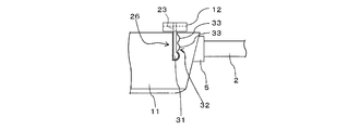
- FIG. 6 is an exploded perspective view showing the vicinity of an image forming unit. It is explanatory drawing which showed the position adjustment mechanism. It is explanatory drawing which showed the position adjustment mechanism. It is explanatory drawing which showed the head mounting unit of the head mounted display which concerns on other embodiment.
- the head-mounted display projects an image light based on image information onto the retina of the user and causes the user to visually recognize the image, and the image forming unit near the eye of the user And a support member for rotatably supporting via a rotation mechanism.
- the rotating shaft of the rotating mechanism is characterized by being arranged coaxially with the vertical motion axis of the eyeball onto which the image light is projected.
- the image forming unit is moved to the user's desired position, image formation is possible.
- the image light emitted from the projection optical system can be incident on the pupil of the user from the direction along the visual axis, and the visibility can be maintained as much as possible.
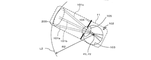
- FIG. 1 shows a side view of image light 101a, 101b, 101c emitted from a projection optical system 100 disposed in front of an eye that emits image light from an image forming unit toward the eyeball.
- the image light incident on the user's pupil is image light with high directivity.
- 1A and 1B show a state in which the rotation axis of the rotation mechanism is arranged near the user's back in the conventional manner
- FIG. 1C shows the rotation axis of the rotation mechanism. It shows a state when it is arranged coaxially with the vertical motion axis of the eyeball.
- the projection optical system 100 disposed in the image forming unit 106 of the head-mounted display shown in FIG. 1A is on a rotation locus L1 separated by a radius R1 around a rotation axis P1 disposed in the vicinity of the user's back of the head. Is configured to move.
- the rotation axis P1 of the projection optical system 100 is not arranged coaxially with the vertical motion axis P2 of the eyeball 102.
- the image lights 101a, 101b, and 101c emitted from the projection optical system 100 disposed in front of the eye pass through the exit pupil 104, form an image on the retina 103 through the lens body 105, and are shown on the right side of FIG. 1A. So that it is recognized as an image by the user.
- the projection optical system 142 disposed in the image forming unit 11 of the head-mounted display shown in FIG. 1C rotates around a rotation axis P3 coaxial with the vertical motion axis P2 of the eyeball 102 with a distance of radius R2. It is configured to move on the locus L2.
- a support member which will be described in detail later, is held via a rotation mechanism, and the rotation axis P3 of the rotation mechanism is arranged coaxially with the vertical motion axis P2 of the eyeball 102.
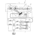
- FIG. 2 is an explanatory diagram showing the overall configuration of the head mounted display A according to the present embodiment.
- the head mounted display A includes a light source unit 1 that emits video light based on a video signal, an optical fiber cable unit 2 that transmits video light emitted from the light source unit 1, and a light receiving unit. And a head-mounted unit 3 for scanning the image light and allowing the user to recognize the image.
- the optical fiber cable portion 2 has a light source side plug 4 formed on one end side and an image forming portion side plug 5 formed on the other end side, and the light source side plug 4 is connected to the light of the light source unit portion 1.
- the image forming unit side plug 5 By inserting the image forming unit side plug 5 into the light receiving jack 7 of the image forming unit 11 provided in the head mounting unit 3, the image light emitted from the light source unit unit 1 is formed into an image. Transmission to the unit 11 is possible.
- the head-mounted unit 3 projects image light onto the user's retina to allow the user to visually recognize the image, and support for supporting the image forming unit 11 in the vicinity of the user's eyes. It consists of the member 10.
- the user can hold the image forming unit 11 in front of the user's eyes by locking the head-mounted unit 3 at three points of both ears and nose column so as to wear glasses.
- the present invention is characterized by the structure of the support member 10 of the head-mounted unit 3, and the support member 10 will be described in detail later.
- the head mounted display A is provided with the light source unit 1 for processing the video signal supplied from the outside and emitting the image light.
- the light source unit 1 is provided with a video signal supply circuit 113 that receives a video signal from the outside and generates each signal as an element for synthesizing the video based on the video signal.
- a signal 114, a horizontal synchronization signal 115, and a vertical synchronization signal 116 are output.
- the light source unit 1 also has an intensity based on the red (R), green (G), and blue (B) video signals 114R, 114G, and 114B transmitted from the video signal supply circuit 113 as video signals.
- An R laser driver 130, a G laser driver 129, and a B laser driver 128 for driving the R laser 123, the G laser 122, and the B laser 121, respectively, are provided so as to emit modulated laser light.
- a collimating optical system 124 provided so as to collimate the laser light emitted from each laser into parallel light, a dichroic mirror 125 for combining the collimated laser lights, and the combined laser light.
- a coupling optical system 126 that guides image light to the optical fiber cable portion 2 is provided.
- a semiconductor laser such as a laser diode or a solid-state laser may be used as the R laser 123, the G laser 122, and the B laser 121.
- the head mounted display A has a collimating optical system 138 for guiding the image light propagated from the light source unit 1 to the horizontal scanning system 139 and the collimated image light in the horizontal direction using the optical scanning element 134.
- a horizontal scanning system 139 that scans, a first relay optical system 140 that guides image light scanned by the horizontal scanning system 139 to the vertical scanning system 141, and a scan that is scanned by the horizontal scanning system 139 and passes through the first relay optical system 140
- a vertical scanning system 141 that scans the incident image light in the vertical direction using a galvano mirror 141a, and a second relay optical so that the image light scanned by the vertical scanning system 141 enters the pupil 144 of the user
- a system 142 projection optical system
- the image light that has been two-dimensionally scanned and entered the user's pupil 144 is projected onto the retina, so that the user can recognize the image by the image light.
- the horizontal scanning system 139 is an optical system that horizontally scans image light in the horizontal direction for each scanning line of an image to be displayed.
- the horizontal scanning system 139 includes an optical scanning element 134 that scans image light in the horizontal direction, and a horizontal scanning control circuit 132 that controls driving of the optical scanning element 134.
- the vertical scanning system 141 is an optical system that vertically scans image light from the first scanning line to the last scanning line for each frame of the image to be displayed.
- the vertical scanning system 141 includes a galvano mirror 141a that performs vertical scanning, and a vertical scanning control circuit 141c that controls driving of the galvano mirror 141a.
- the horizontal scanning system 139 is designed to scan image light at a higher speed, that is, at a higher frequency than the vertical scanning system 141. Further, as shown in FIG. 3, the horizontal scanning system 139 and the vertical scanning system 141 are respectively connected to the video signal supply circuit 113, and are respectively supplied to the horizontal synchronization signal 115 and the vertical synchronization signal 116 output from the video signal supply circuit 113. It is configured to scan image light in synchronization.
- the optical scanning element 134 is used for the horizontal scanning system 139 and the galvano mirror 141a is used for the vertical scanning system 141 so as to scan the image light in the horizontal direction and the vertical direction.
- any drive system such as piezoelectric drive, electromagnetic drive, and electrostatic drive may be used as long as the reflecting surface is swung (rotated) so as to scan light.
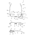
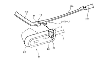
- FIG. 4 is a plan view, a front view, and a left side view of the head-mounted unit 3, and FIG. 5 is an exploded perspective view showing the vicinity of the image forming unit 11.
- the head-mounted unit 3 includes a support member 10 having a substantially glasses shape and an image forming unit 11 that forms an image for the user to recognize. Note that the image forming unit 11 is rotatably held on the support member 10 by a rotation mechanism 27 described later.
- the support member 10 includes a front portion 13 formed so as to be bridged substantially in front of the user's heel when the user wears the head-mounted unit 3, and left and right end portions of the front portion 13 rearward.
- Left and right temple portions 16L and 16R connected to the temple connecting portions 14 and 14 formed by bending toward each other through left and right hinges 15 and 15 are provided.
- Pad feet 17 and 17 extend downward in a substantially central portion of the front portion 13, and the lower ends of the pad feet 17 and 17 are made of resin that is curved in a mountain shape to match the nose column.
- the pad portion 18 is attached.
- left and right temple cells 22L and 22R are attached to the left and right temple portions 16L and 16R, respectively, so that the burden on the ear is reduced when the user wears the head-mounted unit 3. I have to.
- the image forming unit 11 includes an image forming body 24 that houses the horizontal scanning system 139, the vertical scanning system 141, the second relay optical system 142, and the like, and a connecting member for holding the image forming body 24 on the support member 10. 12 with.
- the image forming unit 11 is provided with a light receiving jack 7.
- the light receiving jack 7 has an image forming unit of the optical fiber cable unit 2 for transmitting the image light 101 generated by the light source unit unit 1.
- a side plug 5 is connected.
- a half mirror 21 is disposed at a position substantially opposite to the eyeball of the image forming unit 11.
- the half mirror 21 reflects a part of the image light 101 emitted from the image forming unit 11 via the second relay optical system 142 and transmits a part of the external light, so that the left eyeball of the user Image light 101 and external light can be incident on 102L.
- the image forming unit 11 connects the base portion 19 to the vicinity of the hinge 15 of the left temple portion 16L via a connecting member 12 so as to be freely rotatable, and the left temple portion 16L. It is formed in a substantially L shape in a plan view that is bent at the temple connecting portion 14 to face the user's eyes.
- the connecting member 12 is connected to the image forming main body 24 via a rotating mechanism 27.
- the rotation mechanism 27 has a rotation shaft 23 that is rotatable with respect to the connecting member 12 and that is inserted into the image forming body 24.
- the connecting member 12 is detachably attached to the left temple portion 16L at a position where the vertical movement axis VL of the left eyeball 102L and the left temple portion 16L intersect.
- a mounting portion 25L (see FIG. 5) to be attached to is provided.
- the connecting member 12 to the attachment portion 25L, the image forming portion 11 is held by the support member 10 via the rotation mechanism 27, and the rotation shaft 23 of the rotation mechanism 27 is configured to receive image light. It is arranged coaxially with the vertical motion axis VL of the left eyeball 102L to be projected.
- the vertical movement axis VL of the eyeball is located about 13 mm inward from the top of the cornea to the posterior pole direction. Further, a generally used spectacle lens is disposed at a position of about 12 mm from the top of the cornea to the front of the eyeball axis. Therefore, when the rotation mechanism 27 is disposed at a position about 25 mm rearward from the bent portion of the temple connection portion 14 in the side view of the support member 10, the rotation shaft 23 is substantially coaxial with the vertical motion axis VL. Can be arranged. However, since the position in the vertical direction differs depending on the shape of the user's nose, the height of the ear, and the like, it is preferable to separately provide a mechanism capable of adjusting the position in the vertical direction. In the present embodiment, the position adjustment in the vertical direction will be described later as the position adjustment mechanism 26.
- the connecting member is located at the position where the vertical movement axis VR of the right eyeball 102R and the right temple portion 16R intersect with the right temple portion 16R.
- An attachment portion 25R for detachably attaching 12 is provided.
- the attachment portion 25R has a mirror image symmetrical shape with the attachment portion 25L provided on the left temple portion 16L, and is held by the support member 10 via the rotation mechanism 27 in a state where the image forming portion 11 is reversed left and right.
- the rotation shaft 23 of the rotation mechanism 27 can be arranged coaxially with the vertical motion axis VR of the right eyeball 102R on which the image light is projected.
- the image forming unit 11 can be attached to any of the left and right temple units 16L and 16R, it is possible to appropriately select an eye for recognizing the image according to the user's dominant eye and preference.
- temple parts 16L and 16R are provided with a position adjusting mechanism 26 for adjusting the vertical position and the horizontal position of the image forming part 11.
- the position adjustment mechanism 26 includes a protrusion 31 formed at the tip of the rotation shaft 23, and the protrusion 31 at a plurality of locations within the image forming section 11. And a protrusion receiving portion 32 that fits together.
- the rotation shaft 23 protruded from the rotation mechanism 27 to the image forming unit 11 side is formed in a substantially semicircular shape in sectional view, and a hemispherical protrusion 31 is formed at the tip thereof.
- the protrusion receiving portion 32 is formed by connecting a plurality of hollow hemispherical positioning spaces 33 that can be engaged with the protrusion 31 inside the image forming portion 11 in the vertical and horizontal directions.
- the inner wall surface of the projection receiving portion 32 is formed of a relatively soft synthetic resin material, and the rotation shaft 23 and the projection portion 31 are held in the positioning space 33 to rotate and move in the horizontal and vertical directions. Although the restriction is applied, the projection 31 can be moved to the desired positioning space 33 by applying a force by the user.
- the vertical position and the horizontal direction of the rotation shaft 23 can be appropriately adjusted by engaging the locking position of the protruding portion 31 with the arbitrary positioning space 33 in the protruding portion 32.
- the vertical position of the rotation mechanism 27 and the horizontal position of the image forming unit 11 can be adjusted.
- the protrusion receiving unit 32 may be configured so that only the vertical position adjustment of the rotation mechanism 27 or only the horizontal position adjustment of the image forming unit 11 can be performed.
- the head mounted unit 30 of the head mounted display B has the same basic configuration as the head mounted unit 3 described above, but the configuration of the rotation mechanism is the same. Different. That is, a part or all of the left and right temple parts 16L, 16R of the support member 10 is formed with a wide part 40 that is wide in the vertical direction, and an insertion hole 41 is formed in the wide part 40. The structure is different in that the rotating mechanism 42 is configured by inserting the rotating shaft 23.
- the head mounted display B includes a wide portion 40 formed in the vicinity of the hinge 15 of the left temple portion 16L of the support member 10 and extending vertically downward from the left temple portion 16L.
- the wide portion 40 is provided with an insertion hole 41 through which the rotation shaft 23 projecting from the image forming body 24 can be inserted.
- the rotation shaft 23 is inserted into the insertion hole 41 and the end portion
- the rotation mechanism 42 is configured by screwing the nut 43 into the male screw portion 44 formed in the above.
- the insertion hole 41 is arranged on the same axis as the vertical motion axis VL of the left eyeball 102L, so that the rotation axis 23 of the rotation mechanism 27 can be arranged on the same axis as the vertical movement axis VL.
- the image forming unit is held on the support member via the rotation mechanism, and the rotation axis of the rotation mechanism is coaxial with the vertical motion axis of the eyeball.
- the visibility can be maintained as much as possible even when the user attempts to visually recognize the image at a position where the user has moved the eyeball upward or downward.
Landscapes
- Physics & Mathematics (AREA)
- General Physics & Mathematics (AREA)
- Optics & Photonics (AREA)
Abstract
使用者が眼球を上転又は下転させた位置で画像を視認しようとした場合であっても、視認性を可及的維持することのできるヘッドマウントディスプレイを提供する。
画像情報に基づいた画像光を使用者の網膜に投射して、前記使用者に画像を視認させる画像形成部と、前記画像形成部を前記使用者の眼部近傍で支持するための支持部材とを備えたヘッドマウントディスプレイにおいて、前記画像形成部は、前記支持部材に回動機構を介して保持されており、前記回動機構の回動軸は、前記画像光が投射される眼球の垂直運動軸と同軸上に配置した。
Description
本発明は、頭部に装着して使用するヘッドマウントディスプレイに関する。
近年、使用者の頭部に装着されるタイプの画像表示装置、いわゆるヘッドマウントディスプレイ(Head Mounted Display:HMD)が広く知られている。ヘッドマウントディスプレイは、例えばバーチャルリアリティや個人用シアターとして、既に製品化がなされている。将来的には、その携帯性故に、例えばウェアラブルコンピュータなどの分野においての利用が期待されている。
これらのヘッドマウントディスプレイは、一般的に、使用者の眼前に配設し使用者に認識させるための画像を形成する画像形成部と、同画像形成部を使用者の眼前位置にさせる支持部材とで構成されている。
そして、画像形成部に画像を表示したり、また、画像形成部から画像光を出射して瞳孔に入射させ、網膜に直接結像することで、使用者に画像を認識させるようにしている。
中でも、支持部材の後頭部側面位置に、頭部内方へ軸線を向けた回動機構を設け、この回動機構から頭部前方へ向けて伸延させたアームの先端に画像形成部を配設し、使用者の眼前にて画像形成部を上下方向へ移動可能としたものが知られている(例えば、特許文献1参照。)。
このようなヘッドマウントディスプレイによれば、使用者が所望する位置に画像形成部を移動させることができる。
特開2005-294978号公報
しかしながら、上記従来のヘッドマウントディスプレイでは、使用者の瞳孔へ入射させる画像光を、視野角の狭いLCDからの画像光や、2次元走査されたレーザ光など、指向性の高い画像光の射出瞳が小さい場合、使用者による画像の視認性が低下する場合があった。
具体的には、使用者が眼球を上転させた位置で画像を視認しようとした場合、その視軸上に画像形成部を移動させても、画像光の射出瞳と使用者の瞳孔がずれてしまい、画像全体を観察することができないことがあった。
そこで、本発明は、使用者が眼球を上転又は下転させた位置で画像を視認しようとした場合に、使用者の瞳孔へ入射する画像光の指向性が高くとも、視認性を可及的維持することのできるヘッドマウントディスプレイを提供することを目的とする。
上記目的を達成するために、本発明の一つの観点によれば、ヘッドマウントディスプレイにおいて、画像情報に基づいた画像光を使用者の網膜に投射して、前記使用者に画像を視認させる画像形成部と、前記画像形成部を前記使用者の眼部近傍で支持するための支持部材とを備え、前記画像形成部は、前記支持部材に回動機構を介して保持されており、前記回動機構の回動軸は、前記画像光が投射される眼球の垂直運動軸と同軸上に配置することとした。
このように構成することにより、使用者の眼球が垂直運動した場合であっても、視認性を可及的維持することができる。
また、前記ヘッドマウントディスプレイにおいて、前記支持部材は、フロント部と左右テンプル部とを備え、前記画像形成部は、前記テンプル部に取り付けられ、前記テンプル部から平面視略L字状に屈曲させて前記使用者の眼前に臨ませる構成にしてもよい。
このように構成することにより、眼球の垂直運動軸と、回動軸とを容易に同軸上とすることができ、視認性をより向上させることができる。
また、前記ヘッドマウントディスプレイにおいて、前記回動機構は、前記支持部材のテンプル部を幅広状に形成して挿通孔を穿設するとともに、前記挿通孔に前記回動軸を挿通させる構成にしてもよい。
このように構成することにより、テンプル部を回動機構の一部として使用することができ、回動機構の構成をよりシンプルなものとすることができる。
また、前記ヘッドマウントディスプレイにおいて、前記画像形成部は、画像形成本体と、当該画像形成本体と前記回動機構を介して連結された連結部材とから構成され、前記支持部材のテンプル部に、前記連結部材を着脱自在に取り付ける取り付け部を設ける構成にしてもよい。
このように構成することにより、支持部材と画像形成部とをそれぞれ別体とすることができ、支持部材と画像形成部のメンテナンス性を向上することができる。
また、前記ヘッドマウントディスプレイにおいて、前記画像形成部は、左右のいずれのテンプル部にも取り付け可能とする構成にしてもよい。
このように構成することにより、使用者の利き目や好みに応じて、画像を認識させる眼を適宜選択することができる。
また、前記ヘッドマウントディスプレイにおいて、前記テンプル部に、前記回動機構の上下位置及び/又は前記画像形成部の左右位置、を調整する位置調整機構を備える構成にしてもよい。
このように構成することにより、使用者の眼の垂直運動軸と回動軸とを同軸上とする調整を容易に行うことができる。また、使用者の目の位置に合わせた調整を容易に行うことができる。
本発明によれば、画像情報に基づいた画像光を使用者の網膜に投射して、前記使用者に画像を視認させる画像形成部と、前記画像形成部を前記使用者の眼部近傍で支持するための支持部材とを備え、前記画像形成部は、前記支持部材に回動機構を介して保持されており、前記回動機構の回動軸は、前記画像光が投射される眼球の垂直運動軸と同軸上に配置したため、使用者の眼球が垂直運動した場合であっても、視認性を可及的維持することができる。
1 光源ユニット部
2 光ファイバケーブル部
3 頭部装着ユニット
6 光射出ジャック
7 受光ジャック
10 支持部材
11 画像形成部
12 連結部材
13 フロント部
16 テンプル部
23 回動軸
24 画像形成本体
25 取り付け部
26 位置調整機構
27 回動機構
40 幅広部
41 挿通孔
42 回動機構
101 画像光
102 眼球
103 網膜
138 コリメート光学系
A ヘッドマウントディスプレイ
B ヘッドマウントディスプレイ
P3 回動軸
VL 垂直運動軸
VR 垂直運動軸
2 光ファイバケーブル部
3 頭部装着ユニット
6 光射出ジャック
7 受光ジャック
10 支持部材
11 画像形成部
12 連結部材
13 フロント部
16 テンプル部
23 回動軸
24 画像形成本体
25 取り付け部
26 位置調整機構
27 回動機構
40 幅広部
41 挿通孔
42 回動機構
101 画像光
102 眼球
103 網膜
138 コリメート光学系
A ヘッドマウントディスプレイ
B ヘッドマウントディスプレイ
P3 回動軸
VL 垂直運動軸
VR 垂直運動軸
以下に、本発明の画像表示装置について好適な実施形態について説明する。
本実施形態に係るヘッドマウントディスプレイは、画像情報に基づいた画像光を使用者の網膜に投射して、使用者に画像を視認させる画像形成部と、この画像形成部を使用者の眼部近傍で回動機構を介して回動可能に支持するための支持部材とを備えている。
そして、回動機構の回動軸を、画像光が投射される眼球の垂直運動軸と同軸上に配置し
たことに特徴を有するものである。
たことに特徴を有するものである。
このように構成することで、使用者の瞳孔へ入射する画像光の指向性が高い場合であっても、画像形成部を使用者の所望の位置に移動させた場合であっても、画像形成部の投射光学系から出射する画像光を視軸に沿った方向から使用者の瞳孔へ入射することでき、視認性を可及的に維持可能となる。
従って、ヘッドマウントディスプレイを、「眼球を垂直運動させて所定の方向を注視した際に画像が見え、それ以外の方向を注視した際には画像が見えないようにする」といった用途に使用する場合に、使用者が前記所定の方向を任意の角度に変更しても、画像光を使用者の眼球内に容易に入射させることができ、視認性を確保することができる。
[1.本発明の概念]
まず、本発明の概念について、図1を用いて説明する。図1は画像形成部からの画像光を眼球へ向けて出射する眼前に配設した投射光学系100から出射された画像光101a,101b,101cが、眼球102に入射する様子を側面視で示した説明図であり、使用者の瞳孔へ入射する画像光は、指向性が高い画像光としている。なお、図1A及び図1Bは、従来のように回動機構の回動軸を使用者の後頭部近傍に画像形成部を配置したときの様子を示し、図1Cは回動機構の回動軸を眼球の垂直運動軸と同軸上に配置したときの様子を示している。
まず、本発明の概念について、図1を用いて説明する。図1は画像形成部からの画像光を眼球へ向けて出射する眼前に配設した投射光学系100から出射された画像光101a,101b,101cが、眼球102に入射する様子を側面視で示した説明図であり、使用者の瞳孔へ入射する画像光は、指向性が高い画像光としている。なお、図1A及び図1Bは、従来のように回動機構の回動軸を使用者の後頭部近傍に画像形成部を配置したときの様子を示し、図1Cは回動機構の回動軸を眼球の垂直運動軸と同軸上に配置したときの様子を示している。
図1Aに示すヘッドマウントディスプレイの画像形成部106に配設した投射光学系100は、使用者の後頭部近傍に配設した回動軸P1を中心に半径R1の距離を隔てた回動軌跡L1上を移動するように構成している。
すなわち、図1Aでは、投射光学系100(画像形成部106)の回動軸P1は、眼球102の垂直運動軸P2と同軸上に配設していない。
そして、眼前に配設した投射光学系100から射出された画像光101a,101b,101cは、射出瞳104を通過し、レンズ体105を経て網膜103上で結像され、図1Aの右側に示すように使用者に画像として認識されている。
このような状態において、使用者が眼球102を上転させた位置で画像を視認しようとした場合、図1Bに示すように、画像形成部106を移動させても、画像形成部106の投射光学系100から射出された画像光101a,101b,101cの一部又は全部が瞳孔に入射しない。そのため、使用者は、一部欠失した画像を認識したり、画像が全く見えなかったりすることとなる。
一方、図1Cに示すヘッドマウントディスプレイの画像形成部11に配設した投射光学系142は、眼球102の垂直運動軸P2と同軸の回動軸P3を中心に半径R2の距離を隔てた回動軌跡L2上を移動するように構成している。後に詳述する支持部材に回動機構を介して保持させ、この回動機構の回動軸P3は、眼球102の垂直運動軸P2と同軸上に配置している。
このような構成とすることにより、使用者が眼球102を上転させた位置で画像を視認しようとした場合であっても、画像形成部11を回動軌跡L2に沿って移動させることにより、画像形成部11の投射光学系142から出射される画像光を視軸に沿った方向から使用者の瞳孔へ入射する。そのため、画像光101a,101b,101cは眼球102内に入射し、正面視の場合と同様に鮮明且つ適正な位置に表示させた画像を使用者に認識させることができ、視認性を可及的維持可能なヘッドマウントディスプレイとすることができるのである。
[2.ヘッドマウントディスプレイの全体構成]
次に、本実施形態に係るヘッドマウントディスプレイAの具体的な構成について図面を用いながら説明する。
次に、本実施形態に係るヘッドマウントディスプレイAの具体的な構成について図面を用いながら説明する。
図2は、本実施形態に係るヘッドマウントディスプレイAの全体的な構成を示した説明図である。
図2に示すように、ヘッドマウントディスプレイAは、映像信号に基づいた映像光を射出する光源ユニット部1と、光源ユニット部1から射出された映像光を伝送する光ファイバケーブル部2と、受光した画像光を走査して使用者に画像を認識させるための頭部装着ユニット3とを備えている。
また、光ファイバケーブル部2は、一端側に光源側プラグ4が形成され、また、他端側には画像形成部側プラグ5が形成されており、光源側プラグ4を光源ユニット部1の光射出ジャック6に挿入し、画像形成部側プラグ5を頭部装着ユニット3に備えられた画像形成部11の受光ジャック7に挿入することで、光源ユニット部1から射出された画像光を画像形成部11に伝送可能としている。
頭部装着ユニット3は、画像光を使用者の網膜に投射して、使用者に画像を視認させる画像形成部11と、この画像形成部11を使用者の眼部近傍で支持するための支持部材10とで構成している。
そして、使用者が、この頭部装着ユニット3をメガネをかけるように両耳と鼻柱の3点で係止することで、画像形成部11を使用者の眼前に保持できるようにしている。なお、本願発明は、頭部装着ユニット3の支持部材10の構成に特徴を有するものであり、この支持部材10については、後に詳述する。
次に、ヘッドマウントディスプレイAの電気的及び光学的な構成について図3を用いながら説明する。
ヘッドマウントディスプレイAには、前述のように、外部から供給される映像信号を処理し、画像光を出射するための光源ユニット部1が設けられている。
光源ユニット部1には、外部からの映像信号が入力され、それに基づいて映像を合成するための要素となる各信号を発生する映像信号供給回路113が設けられ、この映像信号供給回路113から映像信号114、水平同期信号115、及び、垂直同期信号116が出力される。
また、光源ユニット部1には、映像信号供給回路113から映像信号として伝達される赤(R),緑(G),青(B)の各映像信号114R,114G,114Bをもとにそれぞれ強度変調されたレーザ光を出射するように、Rレーザ123,Gレーザ122,Bレーザ121を、それぞれ駆動するためのRレーザドライバ130,Gレーザドライバ129,Bレーザドライバ128が設けられている。
さらに、各レーザより出射されたレーザ光を平行光にコリメートするように設けられたコリメート光学系124と、それぞれコリメートされたレーザ光を合波するダイクロイックミラー125と、合波されたレーザ光からなる画像光を光ファイバケーブル部2に導く結合光学系126とが設けられている。
尚、Rレーザ123,Gレーザ122,Bレーザ121として、レーザダイオード等の半導体レーザや固体レーザを利用してもよい。
また、ヘッドマウントディスプレイAには、光源ユニット部1から伝搬された画像光を水平走査系139に導くコリメート光学系138と、コリメートされた画像光を、光走査素子134を利用して水平方向に走査する水平走査系139と、水平走査系139によって走査された画像光を垂直走査系141に導く第1リレー光学系140と、水平走査系139に走査され、第1リレー光学系140を介して入射された画像光を、ガルバノミラー141aを利用して垂直方向に走査する垂直走査系141と、垂直走査系141に走査された画像光を使用者の瞳孔144に入射するように第2リレー光学系142(投射光学系)と、が設けられている。
2次元走査されて使用者の瞳孔144に入射した画像光は網膜上に投影され、これにより使用者はこの画像光による画像を認識することができる。
尚、具体的な一例としては、水平走査系139は、表示すべき画像の1走査線ごとに、画像光を水平方向に水平走査させる光学系である。また、水平走査系139は、画像光を水平方向に走査する光走査素子134と、その光走査素子134の駆動制御を行う水平走査制御回路132とを備えている。
これに対し、垂直走査系141は、表示すべき画像の1フレームごとに、画像光を最初の走査線から最後の走査線に向かって垂直に垂直走査する光学系である。また、垂直走査系141は、垂直走査するガルバノミラー141aと、そのガルバノミラー141aの駆動制御を行う垂直走査制御回路141cとを備えている。
水平走査系139は、垂直走査系141より高速にすなわち高周波数で画像光を走査するように設計されている。また、水平走査系139,垂直走査系141は、図3に示すように、各々映像信号供給回路113に接続され、映像信号供給回路113より出力される水平同期信号115,垂直同期信号116にそれぞれ同期して画像光を走査するように構成されている。
なお、本実施形態においては、水平走査系139に光走査素子134を用い、垂直走査系141にガルバノミラー141aを用いることで水平方向及び垂直方向に画像光を走査するように説明したが、画像光を走査するようにその反射面が揺動(回転)させられるものであれば、圧電駆動、電磁駆動、静電駆動等いずれの駆動方式によるものであってもよいことは言うまでもない。
[3.頭部装着ユニットの具体的構成]
次に、本実施形態の要部を備える頭部装着ユニット3について図4を用いながらさらに詳細に説明する。図4は、頭部装着ユニット3の平面図、正面図、左側面図を示し、図5は、画像形成部11の近傍を示した分解斜視図である。
次に、本実施形態の要部を備える頭部装着ユニット3について図4を用いながらさらに詳細に説明する。図4は、頭部装着ユニット3の平面図、正面図、左側面図を示し、図5は、画像形成部11の近傍を示した分解斜視図である。
頭部装着ユニット3は、略眼鏡形状とした支持部材10と、使用者に認識させるための画像を形成する画像形成部11とを備えている。なお、画像形成部11は、後述する回動機構27により、支持部材10に回動自在に保持されている。
支持部材10は、使用者が頭部装着ユニット3を装着した際に、使用者の瞼の略前方で架け渡されるように形成したフロント部13と、同フロント部13の左右端部を後方へ向けて屈曲して形成したテンプル接続部14,14に左右丁番15,15を介して揺動自在に連結された左右テンプル部16L,16Rとを備えている。
フロント部13の略中央部分には、下方へ向けてパッド足17,17が延出しており、同パッド足17,17の下端部には、鼻柱に合わせて山型に湾曲させた樹脂製のパッド部18が取り付けられている。
また、左右テンプル部16L,16Rには、それぞれ左先セル22L及び右先セル22Rが装着されており、使用者が頭部装着ユニット3を装着した際に、耳への負担が軽減されるようにしている。
画像形成部11は、前述の水平走査系139や垂直走査系141、第2リレー光学系142等を収容した画像形成本体24と、当該画像形成本体24を支持部材10に保持するための連結部材12とを備えている。
この画像形成部11には、受光ジャック7が配設されており、同受光ジャック7には光源ユニット部1にて生成された画像光101を伝送するための光ファイバケーブル部2の画像形成部側プラグ5が接続されている。
画像形成部11の眼球と略対向する位置には、ハーフミラー21が配設されている。このハーフミラー21により、第2リレー光学系142を介して画像形成部11から出射される画像光101の一部を反射させ、また、外光の一部を透過させて、使用者の左眼球102Lへ画像光101と外光とを入射可能としている。
また、画像形成部11は、図4及び図5に示すように、その基部19を左テンプル部16Lの丁番15近傍に連結部材12を介して回動自在に接続すると共に、同左テンプル部16Lからテンプル接続部14部分で屈曲させて使用者の眼前に臨ませた平面視略L字状に形成している。
ここで、連結部材12は、図5に示すように、回動機構27を介して画像形成本体24と連結している。回動機構27は、連結部材12に対して回動自在で、且つ、画像形成本体24に挿入される回動軸23を有している。このように構成することで、眼球の垂直運動軸VLと、回動軸23とを容易に同軸上とすることができ、視認性をより向上させることができる。
また、図4に示した頭部装着ユニット3の平面視において、左テンプル部16Lには、左眼球102Lの垂直運動軸VLと左テンプル部16Lとが交差する位置に、連結部材12を着脱自在に取り付ける取り付け部25L(図5参照)を設けている。
そして、この取り付け部25Lに連結部材12を嵌合させることにより、画像形成部11は支持部材10に回動機構27を介して保持され、回動機構27の回動軸23は、画像光が投射される左眼球102Lの垂直運動軸VLと同軸上に配置される。
通常、眼球の垂直運動軸VLは、角膜頂部から後極方向へ約13mm程内方に位置している。また、一般に使用される眼鏡のレンズは、角膜頂部から眼球軸の前方へ約12mmの位置に配設される。それゆえ、回動機構27は、支持部材10の側面視において、テンプル接続部14の屈曲部から後方へ約25mm程度の部位に配設すると、回動軸23を垂直運動軸VLと略同軸上に配設することができる。ただし、垂直方向の位置については、使用者の鼻の形状や耳の高さ等によりそれぞれ異なるため、垂直方向へ位置調整可能な機構を別途設けるのが好ましい。なお、本実施形態では、後に位置調整機構26として垂直方向への位置調整について説明する。
また、本実施形態における支持部材10では、図4の平面図に示すように、右テンプル部16Rにも、右眼球102Rの垂直運動軸VRと右テンプル部16Rとが交差する位置に、連結部材12を着脱自在に取り付ける取り付け部25Rを設けている。このように構成することで、支持部材10と画像形成部11とをそれぞれ別体とすることができ、支持部材10と画像形成部11のメンテナンス性を向上することができる。
この取り付け部25Rは、左テンプル部16Lに設けた取り付け部25Lと鏡像対称の形状を有しており、画像形成部11を左右反転させた状態で支持部材10に回動機構27を介して保持して、回動機構27の回動軸23を、画像光が投射される右眼球102Rの垂直運動軸VRと同軸上に配置可能としている。このように前記画像形成部11は、左右のいずれのテンプル部16L,16Rにも取り付け可能としたため、使用者の利き目や好みに応じて、画像を認識させる眼を適宜選択することができる。
勿論、画像形成部11が2台ある場合には、左右両側のテンプル部16L,16Rに同時に連結することも可能である。
また、テンプル部16L,16Rには、画像形成部11の上下位置及び左右位置を調整する位置調整機構26を備えている。
具体的には、図6A及び図6Bに示すように、位置調整機構26は、回動軸23の先端部に形成した突起部31と、画像形成部11内部にて突起部31と複数箇所にて嵌合する突起受部32とで構成している。
回動機構27から画像形成部11側へ突出させた回動軸23は、断面視略半円形状に形成されており、その先端部に半球状の突起部31が形成されている。
一方、突起受部32は、画像形成部11の内部に突起部31と係合可能な中空半円球形状の位置決め空間33を上下左右方向に複数連設して形成している。
この突起受部32の内壁面は比較的軟らかい合成樹脂素材にて形成しており、回動軸23や突起部31を位置決め空間33にて包持して回動や左右上下方向への移動を規制するも、使用者が力を加えることで突起部31を所望の位置決め空間33へ移動可能としている。
このような構成によれば、突起部31の係止場所を突起受部32内の任意の位置決め空間33に係合させることで、回動軸23の上下方向及び左右方向を適宜調整することができ、回動機構27の上下位置及び画像形成部11の左右位置を調整することができる。このように使用者の眼の垂直運動軸VL,VRと回動軸23とを同軸上とする調整を容易に行うことができる。また、使用者の目の位置に合わせた調整を容易に行うことができる。なお、回動機構27の上下位置調整のみ、又は画像形成部11の左右位置調整のみを行うことができるように突起受部32を構成するようにしてもよい。
[4.他の実施形態]
次に、本発明に係る他の実施形態について図7を用いながら説明する。
次に、本発明に係る他の実施形態について図7を用いながら説明する。
図7に示すように、他の実施形態に係るヘッドマウントディスプレイBの頭部装着ユニット30は、前述の頭部装着ユニット3と基本的な構成を同じくしているが、回動機構の構成が異なる。すなわち、支持部材10の左右テンプル部16L,16Rの一部または全部を上下方向へ幅広状の幅広部40を形成して同幅広部40に挿通孔41を穿設するとともに、その挿通孔41に回動軸23を挿通させて回動機構42を構成している点で構造を異にしている。
具体的に説明すると、ヘッドマウントディスプレイBは、支持部材10の左テンプル部16Lの丁番15近傍に、左テンプル部16Lから鉛直下方へ向けて形成した幅広部40を備えている。
また、この幅広部40には、画像形成本体24に突設した回動軸23を挿通可能な挿通孔41が穿設されており、この挿通孔41に回動軸23を挿通し、端部に形成した雄ネジ部44へナット43を螺合させることにより、回動機構42を構成している。挿通孔41は左眼球102Lの垂直運動軸VLと同軸上に配置されており、これにより、回動機構27の回動軸23を垂直運動軸VLと同軸上に配置可能としている。このように構成することで、テンプル部16L,16Rを回動機構42の一部として使用することができ、回動機構42の構成をよりシンプルなものとすることができる。
このような回動機構42によっても、使用者の眼球が垂直運動した場合であっても、視認性を可及的維持することのできるヘッドマウントディスプレイとすることができる。
上述してきたように、本実施形態に係るヘッドマウントディスプレイによれば、画像形成部を支持部材に回動機構を介して保持し、回動機構の回動軸を眼球の垂直運動軸と同軸上に配置したことにより、使用者が眼球を上転又は下転させた位置で画像を視認しようとした場合であっても、視認性を可及的維持することができる。
なお、上述した各実施の形態の説明は本発明の一例であり、本発明は上述の実施の形態に限定されることはない。このため、上述した各実施の形態以外であっても、本発明に係る技術的思想を逸脱しない範囲であれば、設計等に応じて種々の変更が可能であることは勿論である。
Claims (6)
- 画像情報に基づいた画像光を使用者の網膜に投射して、前記使用者に画像を視認させる画像形成部と、
前記画像形成部を前記使用者の眼部近傍で支持するための支持部材とを備え、
前記画像形成部は、前記支持部材に回動機構を介して保持されており、前記回動機構の回動軸は、前記画像光が投射される眼球の垂直運動軸と同軸上に配置したヘッドマウントディスプレイ。 - 前記支持部材は、フロント部と左右テンプル部とを備え、
前記画像形成部は、前記テンプル部に取り付けられ、前記テンプル部から平面視略L字状に屈曲させて前記使用者の眼前に臨ませている
ことを特徴とする請求項1に記載のヘッドマウントディスプレイ。 - 前記回動機構は、前記支持部材のテンプル部を幅広状に形成して挿通孔を穿設するとともに、前記挿通孔に前記回動軸を挿通させて構成した
ことを特徴とする請求項1または請求項2に記載のヘッドマウントディスプレイ。 - 前記画像形成部は、画像形成本体と、当該画像形成本体と前記回動機構を介して連結された連結部材とから構成され、
前記支持部材のテンプル部に、前記連結部材を着脱自在に取り付ける取り付け部を設けた
ことを特徴とする請求項1または請求項2に記載のヘッドマウントディスプレイ。 - 前記画像形成部は、左右のいずれのテンプル部にも取り付け可能とした
ことを特徴とする請求項2~4のいずれか1項に記載のヘッドマウントディスプレイ。 - 前記テンプル部に、前記回動機構の上下位置及び/又は前記画像形成部の左右位置、を調整する位置調整機構を備えた
ことを特徴とする請求項2~5のいずれか1項に記載のヘッドマウントディスプレイ。
Applications Claiming Priority (2)
| Application Number | Priority Date | Filing Date | Title |
|---|---|---|---|
| JP2008244993A JP2010078726A (ja) | 2008-09-24 | 2008-09-24 | ヘッドマウントディスプレイ |
| JP2008-244993 | 2008-09-24 |
Publications (1)
| Publication Number | Publication Date |
|---|---|
| WO2010035536A1 true WO2010035536A1 (ja) | 2010-04-01 |
Family
ID=42059545
Family Applications (1)
| Application Number | Title | Priority Date | Filing Date |
|---|---|---|---|
| PCT/JP2009/056241 Ceased WO2010035536A1 (ja) | 2008-09-24 | 2009-03-27 | ヘッドマウントディスプレイ |
Country Status (2)
| Country | Link |
|---|---|
| JP (1) | JP2010078726A (ja) |
| WO (1) | WO2010035536A1 (ja) |
Cited By (1)
| Publication number | Priority date | Publication date | Assignee | Title |
|---|---|---|---|---|
| WO2017113757A1 (zh) * | 2015-12-31 | 2017-07-06 | 北京小鸟看看科技有限公司 | 一种环绕式界面布局方法、三维沉浸式环境下内容切换方法和列表切换方法 |
Families Citing this family (4)
| Publication number | Priority date | Publication date | Assignee | Title |
|---|---|---|---|---|
| JP5589992B2 (ja) * | 2011-08-23 | 2014-09-17 | ブラザー工業株式会社 | ヘッドマウントディスプレイ |
| WO2013027714A1 (ja) * | 2011-08-23 | 2013-02-28 | ブラザー工業株式会社 | ヘッドマウントディスプレイ |
| JP6701673B2 (ja) | 2015-10-30 | 2020-05-27 | セイコーエプソン株式会社 | ヘッドマウントディスプレイ |
| CN107656382B (zh) | 2017-10-19 | 2019-12-27 | 歌尔科技有限公司 | 一种增强现实眼镜 |
Citations (2)
| Publication number | Priority date | Publication date | Assignee | Title |
|---|---|---|---|---|
| JP2005195822A (ja) * | 2004-01-06 | 2005-07-21 | Scalar Corp | 画像表示装置 |
| JP2007163634A (ja) * | 2005-12-12 | 2007-06-28 | Olympus Corp | 情報表示装置 |
-
2008
- 2008-09-24 JP JP2008244993A patent/JP2010078726A/ja active Pending
-
2009
- 2009-03-27 WO PCT/JP2009/056241 patent/WO2010035536A1/ja not_active Ceased
Patent Citations (2)
| Publication number | Priority date | Publication date | Assignee | Title |
|---|---|---|---|---|
| JP2005195822A (ja) * | 2004-01-06 | 2005-07-21 | Scalar Corp | 画像表示装置 |
| JP2007163634A (ja) * | 2005-12-12 | 2007-06-28 | Olympus Corp | 情報表示装置 |
Cited By (2)
| Publication number | Priority date | Publication date | Assignee | Title |
|---|---|---|---|---|
| WO2017113757A1 (zh) * | 2015-12-31 | 2017-07-06 | 北京小鸟看看科技有限公司 | 一种环绕式界面布局方法、三维沉浸式环境下内容切换方法和列表切换方法 |
| US10372289B2 (en) | 2015-12-31 | 2019-08-06 | Beijing Pico Technology Co., Ltd. | Wraparound interface layout method, content switching method under three-dimensional immersive environment, and list switching method |
Also Published As
| Publication number | Publication date |
|---|---|
| JP2010078726A (ja) | 2010-04-08 |
Similar Documents
| Publication | Publication Date | Title |
|---|---|---|
| US8123352B2 (en) | Head mounted display | |
| TWI870411B (zh) | 具有能調節瞳距的機構的雙目型頭戴式顯示系統 | |
| JP5389493B2 (ja) | 眼鏡装着型画像表示装置 | |
| US10718950B2 (en) | Head-mounted display apparatus | |
| EP1544664A1 (en) | Image display device | |
| JP2017068045A (ja) | ウェアラブル装置 | |
| JP6500793B2 (ja) | 取付具、表示システム、及び、取付システム | |
| CN106199963A (zh) | 显示装置及其控制方法以及计算机程序 | |
| JP6281455B2 (ja) | ヘッドマウントディスプレイ | |
| JP2010078726A (ja) | ヘッドマウントディスプレイ | |
| JP5223760B2 (ja) | ヘッドマウントディスプレイ | |
| JP2001305474A (ja) | 頭部装着型映像表示装置 | |
| JP5163535B2 (ja) | ヘッドマウントディスプレイ | |
| JP5267256B2 (ja) | ヘッドマウントディスプレイ | |
| JP2008009326A (ja) | 画像表示装置及び網膜走査型画像表示装置 | |
| JP6274531B2 (ja) | ヘッドマウントディスプレイ | |
| JP2014153388A (ja) | ヘッドマウントディスプレイ | |
| US9091848B2 (en) | Wearable displays with holders that retain displays at particular positions | |
| JP6703513B2 (ja) | 画像表示装置 | |
| JP2020126246A (ja) | 画像表示装置 | |
| WO2013027714A1 (ja) | ヘッドマウントディスプレイ | |
| JP6164231B2 (ja) | ヘッドマウントディスプレイ及び画像表示装置 | |
| JP4022931B2 (ja) | 頭部装着型表示装置 | |
| JPH11133349A (ja) | 頭部装着型表示装置 | |
| JP7643887B2 (ja) | 眼鏡型映像表示装置 |
Legal Events
| Date | Code | Title | Description |
|---|---|---|---|
| 121 | Ep: the epo has been informed by wipo that ep was designated in this application |
Ref document number: 09815954 Country of ref document: EP Kind code of ref document: A1 |
|
| NENP | Non-entry into the national phase |
Ref country code: DE |
|
| 122 | Ep: pct application non-entry in european phase |
Ref document number: 09815954 Country of ref document: EP Kind code of ref document: A1 |