WO2010032426A1 - 薬剤払出装置および薬剤払出方法 - Google Patents
薬剤払出装置および薬剤払出方法 Download PDFInfo
- Publication number
- WO2010032426A1 WO2010032426A1 PCT/JP2009/004578 JP2009004578W WO2010032426A1 WO 2010032426 A1 WO2010032426 A1 WO 2010032426A1 JP 2009004578 W JP2009004578 W JP 2009004578W WO 2010032426 A1 WO2010032426 A1 WO 2010032426A1
- Authority
- WO
- WIPO (PCT)
- Prior art keywords
- card
- tray
- rewrite
- unit
- transporter
- Prior art date
- Legal status (The legal status is an assumption and is not a legal conclusion. Google has not performed a legal analysis and makes no representation as to the accuracy of the status listed.)
- Ceased
Links
Images


Classifications
-
- G—PHYSICS
- G07—CHECKING-DEVICES
- G07F—COIN-FREED OR LIKE APPARATUS
- G07F5/00—Coin-actuated mechanisms; Interlocks
- G07F5/18—Coin-actuated mechanisms; Interlocks specially adapted for controlling several coin-freed apparatus from one place
-
- G—PHYSICS
- G07—CHECKING-DEVICES
- G07F—COIN-FREED OR LIKE APPARATUS
- G07F11/00—Coin-freed apparatus for dispensing, or the like, discrete articles
- G07F11/02—Coin-freed apparatus for dispensing, or the like, discrete articles from non-movable magazines
- G07F11/44—Coin-freed apparatus for dispensing, or the like, discrete articles from non-movable magazines in which magazines the articles are stored in bulk
-
- G—PHYSICS
- G07—CHECKING-DEVICES
- G07F—COIN-FREED OR LIKE APPARATUS
- G07F11/00—Coin-freed apparatus for dispensing, or the like, discrete articles
- G07F11/64—Coin-freed apparatus for dispensing, or the like, discrete articles in which the articles are individually suspended from stationary supports
-
- G—PHYSICS
- G07—CHECKING-DEVICES
- G07F—COIN-FREED OR LIKE APPARATUS
- G07F17/00—Coin-freed apparatus for hiring articles; Coin-freed facilities or services
- G07F17/0092—Coin-freed apparatus for hiring articles; Coin-freed facilities or services for assembling and dispensing of pharmaceutical articles
-
- G—PHYSICS
- G07—CHECKING-DEVICES
- G07F—COIN-FREED OR LIKE APPARATUS
- G07F9/00—Details other than those peculiar to special kinds or types of apparatus
- G07F9/002—Vending machines being part of a centrally controlled network of vending machines
-
- G—PHYSICS
- G16—INFORMATION AND COMMUNICATION TECHNOLOGY [ICT] SPECIALLY ADAPTED FOR SPECIFIC APPLICATION FIELDS
- G16H—HEALTHCARE INFORMATICS, i.e. INFORMATION AND COMMUNICATION TECHNOLOGY [ICT] SPECIALLY ADAPTED FOR THE HANDLING OR PROCESSING OF MEDICAL OR HEALTHCARE DATA
- G16H10/00—ICT specially adapted for the handling or processing of patient-related medical or healthcare data
- G16H10/60—ICT specially adapted for the handling or processing of patient-related medical or healthcare data for patient-specific data, e.g. for electronic patient records
- G16H10/65—ICT specially adapted for the handling or processing of patient-related medical or healthcare data for patient-specific data, e.g. for electronic patient records stored on portable record carriers, e.g. on smartcards, RFID tags or CD
-
- G—PHYSICS
- G16—INFORMATION AND COMMUNICATION TECHNOLOGY [ICT] SPECIALLY ADAPTED FOR SPECIFIC APPLICATION FIELDS
- G16H—HEALTHCARE INFORMATICS, i.e. INFORMATION AND COMMUNICATION TECHNOLOGY [ICT] SPECIALLY ADAPTED FOR THE HANDLING OR PROCESSING OF MEDICAL OR HEALTHCARE DATA
- G16H20/00—ICT specially adapted for therapies or health-improving plans, e.g. for handling prescriptions, for steering therapy or for monitoring patient compliance
- G16H20/10—ICT specially adapted for therapies or health-improving plans, e.g. for handling prescriptions, for steering therapy or for monitoring patient compliance relating to drugs or medications, e.g. for ensuring correct administration to patients
- G16H20/13—ICT specially adapted for therapies or health-improving plans, e.g. for handling prescriptions, for steering therapy or for monitoring patient compliance relating to drugs or medications, e.g. for ensuring correct administration to patients delivered from dispensers
-
- A—HUMAN NECESSITIES
- A61—MEDICAL OR VETERINARY SCIENCE; HYGIENE
- A61J—CONTAINERS SPECIALLY ADAPTED FOR MEDICAL OR PHARMACEUTICAL PURPOSES; DEVICES OR METHODS SPECIALLY ADAPTED FOR BRINGING PHARMACEUTICAL PRODUCTS INTO PARTICULAR PHYSICAL OR ADMINISTERING FORMS; DEVICES FOR ADMINISTERING FOOD OR MEDICINES ORALLY; BABY COMFORTERS; DEVICES FOR RECEIVING SPITTLE
- A61J2205/00—General identification or selection means
- A61J2205/30—Printed labels
-
- A—HUMAN NECESSITIES
- A61—MEDICAL OR VETERINARY SCIENCE; HYGIENE
- A61J—CONTAINERS SPECIALLY ADAPTED FOR MEDICAL OR PHARMACEUTICAL PURPOSES; DEVICES OR METHODS SPECIALLY ADAPTED FOR BRINGING PHARMACEUTICAL PRODUCTS INTO PARTICULAR PHYSICAL OR ADMINISTERING FORMS; DEVICES FOR ADMINISTERING FOOD OR MEDICINES ORALLY; BABY COMFORTERS; DEVICES FOR RECEIVING SPITTLE
- A61J7/00—Devices for administering medicines orally, e.g. spoons; Pill counting devices; Arrangements for time indication or reminder for taking medicine
- A61J7/0069—Trays for holding or distributing medicines
Definitions
- the present invention relates to a medicine dispensing apparatus and a medicine dispensing method for dispensing a medicine stored in a cassette or the like to a transporter.
- FIG. 12 is an overall configuration diagram of a conventional medicine dispensing apparatus 100 (see, for example, Patent Document 1).
- the medicine dispensing device 100 includes a cassette 102 containing a medicine 104, a shelf 103 for storing the cassette, and a device 105 for taking out the medicine.
- the shelf 103 is divided into a large number of vertical and horizontal, and a plurality of cells 123 are formed. Each cell 123 stores a cassette 102 filled with a medicine 104.
- One cassette 102 is filled with, for example, several tens of medicines 104 of the same type.
- the apparatus 105 has an extraction unit 106 for taking out the medicine from the cassette 102.
- the take-out unit 106 is controlled by a predetermined control device and moves in the direction of the arrow 12A in the figure and the arrow 13A in the figure.
- the take-out unit 106 is positioned with respect to the cassette 102 containing the desired medicine 104 on the rear surface 3B of the storage shelf.
- the extraction unit 106 has a unit similar to a known robot arm (not shown). The robot arm takes out the medicine 104 from the cassette 102 and pays it out to the payout tray 141.
- the payout tray 141 is divided into a plurality of regions by a partition plate 142.
- the drug to be dispensed is dispensed to each area according to the application category.
- the dispensing tray 141 from which the medicine 104 has been dispensed is transported to an application place, for example, a ward.
- each tray needs to display information identifying the patient. This is to ensure that the stored medicine or the like is correctly delivered to the patient or used correctly for the patient.
- a display label as a display means for identifying a tray that is a transporter.
- the display label is obtained by printing patient identification information or the like on a name tag paper or an adhesive label.
- the label is manually attached to the side of the tray and removed manually when the tray is finished.
- a rewrite card that can be repeatedly written is used for attaching and removing the display label due to a large work load (for example, Patent Document 2).
- FIG. 13 shows a conventional medicine dispensing apparatus 200 that automatically attaches a card as a display member to a tray in a detachable manner.
- the medicine dispensing device 200 includes a card attachment / detachment transfer unit 210 and a writing unit 220.
- the card attaching / detaching / transferring unit 210 transfers the rewrite card 201 to / from the tray T between the tray T and the writing unit 220.
- the writing means 220 writes patient identification information on the rewrite card 201.
- the writing unit 220 is connected to the card attachment / detachment transfer unit 210.
- the rewrite card 201 attached to the tray T is removed by the card attaching / detaching / transferring means 210.
- the removed rewritable card 201 is sent between the rubber roller 212 and the plastic roller of the card attaching / detaching and transferring means 210 and transferred to the writing means 220.
- the transferred rewritable card 201 is printed by the writing means 220 and then sent again along the rubber roller 212 and the plastic roller, and attached to the tray T by the card attaching / detaching transferring means 210.
- each tray T is transported with the rewrite card 201 before printing attached, and temporarily stops at the card attachment / detachment transfer means 210.
- the card attachment / detachment transfer means 210 removes the rewrite card 201 from the tray T and transfers it to the writing means 220.
- the rewrite card 201 printed by the writing means 220 is transferred again by the card attaching / detaching transferring means 210 and attached to the stopped tray T.
- the tray T being transported must wait at the card attachment / detachment transfer means 210 until the rewrite card 201 is printed and returned, the waiting time of the tray T becomes long, and the transport efficiency of the tray T is improved. Getting worse. As a result, the medicine dispensing efficiency of the entire apparatus is deteriorated.
- An object of the present invention is to provide a medicine dispensing apparatus and a medicine dispensing method that improve the efficiency of medicine dispensing by shortening the waiting time of the transporter.
- a medicine dispensing apparatus is a medicine dispensing apparatus for dispensing a stored medicine to a portable device to which a card on which desired information is displayed can be attached, and includes a transport unit and a card supply unit. And a card attachment part and a card creation part.
- the transport unit sequentially transports a plurality of transporters.
- a card supply part supplies the 1st card
- the card attachment unit acquires the second card attached to the plurality of transporters and attaches the second card to the second transporter transported after the first transporter.
- the card creation unit displays patient identification information on the first card and the second card.
- the card attached to the first transporter transported first is acquired and desired information is written, and the desired information is written to the first card supplied from the card supply unit to the first transporter.
- Write and install And it attaches after acquiring and writing the 2nd card
- the drug is a drug that can be a subject of prescription, and includes, for example, injections, internal medicines, ointments, patches, suppositories, and the like.
- the patient identification information includes, for example, the patient name, ID number, sex, date of birth, department name, ward name, room number, and the like.
- the card supply unit for example, a card stocker storing a plurality of cards may be provided, or the first first card is held in a card holding part such as a card attachment unit or a card creation unit. You may let them.
- the second transporter includes all transporters transported after the first transporter transported first.
- the second card includes a card attached to the first transporter and all cards attached to the second transporter transported thereafter.
- the first card to be attached to the first transporter that has been transported first is prepared in advance by writing information necessary until the first transporter is transported.
- curd can be efficiently attached with respect to the 1st carrying device conveyed.
- the second transporter transported second the second card acquired from the first transporter is acquired and necessary information is written, and the second transporter is transported.
- the card acquired from the second transporter that has been transported first can be efficiently attached to the transporter (second transporter) transported after the third one.
- the waiting time of the carrying device when the card is attached is shortened, the carrying efficiency of the carrying device is improved, and as a result, the medicine dispensing efficiency can be improved.
- the carrying device to which the card attaching unit is to be attached the second card is not limited to the carrying device that has been transported next to the carrying device that acquired the second card, and after or after that. It may be a later transporter. In this way, the interval from when the second card is acquired to when it is attached can be determined flexibly according to the card creation time in the card creation unit, the transport speed of the transporter, and the like.
- the medicine dispensing device is the medicine dispensing device according to the first invention, wherein the card attachment unit acquires the second card from the first carrier and supplies it to the card creation unit. At about the same time, the first card is attached to the first carrier. The card attachment unit also obtains the second card from the second carrier and attaches the second card obtained previously to the second carrier almost simultaneously with the supply to the card creation unit.
- the card (first card) is attached to the first transporter almost simultaneously with the acquisition of the next card (second card) from the first transporter transported first.
- the created card is attached to the second transporter almost simultaneously with the acquisition of the next card (another second card) from the second transporter transported after the first transporter.
- the medicine dispensing device according to the third invention is the medicine dispensing device according to the first or second invention, and the card is a rewrite card.
- the rewritable card is, for example, a leuco-type card in which a leuco dye in the recording layer and a developer react and combine to form a color, or a so-called cloudy rewritable card.
- the leuco-type rewrite card utilizes the property of being colored (dye and developer are combined) when heated and cooled rapidly at high temperature, and erased (dye and developer are separated) when heated and cooled slowly at low temperature. Information can be rewritten.
- a rewritable card that can be rewritten is used.
- the card inserted into the transporter can be used in the state of being attached to the transporter as it is when the medicine is dispensed next time, so that the trouble of inserting the card again can be saved.
- a medicine dispensing device is the medicine dispensing device according to any one of the first to third inventions, wherein the card supply unit is a card storage unit for storing a spare card, The card creation unit obtains the first card from the card storage unit.
- a card storage unit is provided as a new card supply source.
- curd (1st card
- the medicine dispensing device according to the fifth invention is the medicine dispensing device according to the fourth invention, wherein the card creation unit cannot obtain the second card from the first carrier or the second carrier. A second card is obtained from the card storage unit.
- the second card is supplied from the card storage unit in an emergency in which a new card cannot be obtained.
- a card is selectively supplied from the card storage unit when a new card cannot be acquired from the transporter or when acquisition fails.
- a medicine dispensing method is a medicine dispensing method for dispensing a stored medicine with respect to a portable device to which a card on which desired information is displayed can be attached.
- the transport step the plurality of transporters are transported sequentially.
- the first card attached to the first transporter that is transported first among the plurality of transporters is supplied.
- the attaching step the second card attached to the plurality of transporters is acquired, and the second card is attached to the second transporter transported after the first transporter.
- patient identification information is written to the first card and the second card.
- the first card to be attached to the first transporter that has been transported first is prepared in advance by writing information necessary until the first transporter is transported.
- curd can be efficiently attached with respect to the 1st carrying device conveyed.
- the second transporter transported second the second card acquired from the first transporter is acquired and necessary information is written, and the second transporter is transported.
- the card acquired from the second transporter that has been transported first can be efficiently attached to the transporter (second transporter) transported after the third one.
- the waiting time of the carrying device when the card is attached is shortened, the carrying efficiency of the carrying device is improved, and as a result, the medicine dispensing efficiency can be improved.
- the medicine dispensing efficiency can be improved by reducing the waiting time of the transporter.
- medicine is a drug that can be a subject of prescription, and includes, for example, injections, internal medicines, ointments, patches, suppositories, and the like.
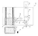
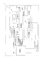
- FIG. 1 shows the appearance of a drug dispensing device 1 according to this embodiment.
- the drug dispensing device 1 performs a drug dispensing process according to patient identification information, drug application information, prescription information, and the like. As shown in FIG. 2, the medicine dispensing apparatus 1 also collects a rewrite card RC before rewriting (hereinafter referred to as a pre-print rewrite card RC) from each tray (carrying device) T that is carried in, and at the same time, performs card processing.
- a rewrite card RC after rewriting (hereinafter referred to as a rewrite card RC after printing) is automatically attached by the unit 10 (FIG. 2).
- the identification information and prescription information of each patient are transmitted from the electronic medical chart system 300 to a management device 310 such as a server.
- Patient identification information includes, for example, the patient's name, ID number, gender, date of birth, department name, ward name, room number, etc., and the contents are in the rewrite card RC, tray label, application label, prescription, etc. Is displayed.
- the drug application information includes the name and dose of the drug applied to the patient, the date and time when the drug is applied, and the contents are mainly displayed on the application label.
- the prescription information is the contents described in the prescription, and includes, in addition to the patient identification information, the name of the medicine to be prescribed and its dose, the application date and time, the single application amount, the application method, and the like. Note that these pieces of information are not strictly divided, and may be partially or entirely duplicated.
- identification information of each patient, medication application information, prescription information, and the like are transmitted to the management device 310.
- Each tray T to be transported is a container of A4 or A3 size.
- a rewrite card RC before printing is attached to the card holder 4 (FIG. 3) on each tray T before conveyance.
- the card holder 4 is attached to one end surface of the tray T on the card processing unit 10 side, as shown in FIG. As shown in the figure, the card holder 4 is formed such that the upper part is inclined toward the card processing unit 10 with respect to the vertical surface of the tray T.
- the card holder 4 has an opening at the top, and the rewrite card RC is inserted through the opening. Note that the card holder 4 may be opened on the side so that the rewrite card RC can be inserted from the side.
- Rewrite card RC is a rewritable card.
- the rewrite card is, for example, a leuco card that develops color by reacting and combining the leuco dye of the recording layer and the developer, or a so-called cloudy rewrite card.
- the leuco-type rewrite card utilizes the property of being colored (dye and developer are combined) when heated and cooled rapidly at high temperature, and erased (dye and developer are separated) when heated and cooled slowly at low temperature. Information can be rewritten. Instead of the rewrite card, another card-like object whose display can be changed may be used.
- the rewrite card RC is mainly printed with patient identification information.
- the medicine dispensing apparatus 1 includes, as main components, a tray supply unit 2, a medicine dispensing unit 3, a tray transport path P, a label / prescription issuing unit 6 (FIG. 7), a completion tray stacking unit 7, and a card. And a processing unit 10. Further, the medicine dispensing device 1 includes a device control unit 5 and a management device 310 (FIG. 8) as a control unit, and controls each unit.
- the tray supply unit 2 sends out the stacked trays T one by one to the tray conveyance path P in response to a command from the device control unit 5 of the medicine dispensing device 1.
- the tray T is transported in the direction of the arrow in FIG. 1 along the tray transport path P, and temporarily stops at a predetermined position near the medicine dispensing unit 3.
- the medicine dispensing unit 3 is arranged on the downstream side of the tray supply unit 2 so as to face the conveyance path P.
- the medicine dispensing unit 3 includes medicine storage means such as a cassette for storing medicine and a drawer, and pick-up means for automatically taking out medicine from the medicine storage means and dispensing it into the tray T.
- the medicine is put in a container such as an ampoule, a vial, a plastic bottle, a kit, or a bag, and is stored in advance in the medicine storage means.
- the pickup means is composed of a robot arm or the like.
- the pick-up means picks up a drug in accordance with a command from the apparatus control unit 5 based on the identification information and prescription information of each patient, and dispenses it to the tray T.
- the card processing unit 10 is arranged on the downstream side of the medicine dispensing unit 3 so as to face the conveyance path P (conveyance unit), takes out the rewrite card RC before printing on the tray T, and automatically puts the rewrite card RC after printing on the tray T. Install it.
- the card processing unit 10 includes a handling mechanism (card attachment unit) 20, a card transfer mechanism (card supply unit) 30, a card position regulation mechanism 40, a card printing mechanism (card creation unit) 50, and a card stocker (card supply). Part (card storage part) 70. The detailed configuration of the card processing unit 10 will be described in detail later.
- the label / prescription issuing unit 6 is disposed above the card processing unit 10 as shown in FIG.
- the label / prescription issuing unit 6 normally prints application labels and prescriptions.
- the label / prescription issuing unit 6 also selectively prints a tray label instead of the card RC when the card processing unit 10 generates an error and puts it in the tray T. Similar to the rewrite card RC, patient identification information is mainly printed on the tray label. In addition to the patient identification information, the application information of the medicine is printed on the application label. When the tray label and the enforcement label are issued together, they may be printed on a single sheet that can be divided, or may be printed on separate sheets.
- the completed tray stacking unit 7 loads and holds a tray T to which a medicine, a rewrite card RC (or tray label) after printing, an application label, a prescription, and the like are supplied.
- the loaded tray T is carried out by a cart.
- the medicine in the tray T carried out by the cart is prescribed to the patient through a drug inspection process.
- the medicine dispensing device 1 includes a device control unit 5 (FIG. 8) and a management device 310 that function as a control unit.
- the apparatus control unit 5 is a computer that controls the medicine dispensing apparatus 1, and includes a tray supply unit 2, a medicine dispensing unit 3, a tray conveyance path P, a label / prescription issuing unit 6, a completed tray stacking unit 7, and a card processing unit. 10 etc. are controlled.
- the management device 310 is a computer that controls the medicine dispensing device 1.
- the management device 310 receives identification information of each patient, medication application information, prescription information, and the like from the electronic medical record system 300. Based on the request or the like, a rewrite card RC, tray label, application label, prescription issuance command or rewrite card RC supply command is issued.
- the medicine dispensing device 1 focusing on the configuration and control of each mechanism of the card processing unit 10 which is a characteristic part of the present invention.
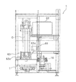
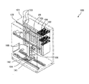
- FIG. 2 is a diagram schematically showing the card processing unit 10.
- the card processing unit 10 prints patient identification information on the pre-print rewrite card RC, and automatically attaches the post-print rewrite card RC to the tray T on which the medicine is loaded.
- the card processing unit 10 provides means for more reliably detaching the rewrite card RC from the tray T and reducing the time during which the tray T is stopped as much as possible.
- the card processing unit 10 includes a handling mechanism 20, a card transfer mechanism 30, a card position regulation mechanism 40, a card printing mechanism 50, and a card stocker 70.
- the handling mechanism 20 is arranged facing the tray conveyance path P.
- the handling mechanism 20 acquires the pre-print rewrite card RC inserted into the card holder 4 of the tray T, and attaches the post-print rewrite card RC held by the card transfer mechanism 30 to the tray T.
- the card transfer mechanism 30 is arranged behind the handling mechanism 20.
- the card transfer mechanism 30 holds the rewrite card RC, reverses the front and back as necessary, and inserts or removes the rewrite card RC from the card printing mechanism 50.
- the card position regulating mechanism 40 is arranged in an L shape with respect to the handling mechanism 20 as shown in FIG.
- the card position regulating mechanism 40 positions the planar rewrite card RC so as to sandwich both sides and corners of the rewrite card RC placed along a substantially horizontal direction.
- the card printing mechanism 50 is arranged so as to be connected to the card position adjusting mechanism 40, and together with the card position adjusting mechanism 40, forms a transfer path for the rewrite card RC parallel to the tray transport path P.
- the card printing mechanism 50 prints patient identification information on a pre-print rewrite card RC, and creates a post-print rewrite card RC attached to the tray T.
- the card stocker 70 is arranged following the card printing mechanism 50, and forms a transfer path for the rewrite card RC parallel to the tray transport path P together with the card position regulating mechanism 40 and the card printing mechanism 50.
- the card stocker 70 stores a plurality of pre-print rewrite cards RC, and supplies the pre-print rewrite cards RC to the card printing mechanism 50 as necessary.
- the card stocker 70 supplies a pre-print rewrite card RC1 (first card) attached to the tray T1 (first transporter) that is transported first after the medicine dispensing device 1 is started.
- the card stocker 70 also fails to acquire the pre-print rewrite card RC (second card) from the tray T1 or the tray T2 (second transporter) transported after the tray T1, or when acquisition fails. For example, a pre-print rewrite card RC (second card) attached to the next tray T2 is supplied.
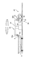
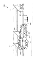
- the handling mechanism 20 includes an arm 21, a pair of card gripping portions 22a and 22b, a pair of support portions 23a and 23b, a pair of guide portions 24a and 24b, a vertical rotation shaft 25, A first card sensor (card detection unit) 26 and a third card sensor 27 are included.
- the center of the arm 21 is supported by a vertical rotation shaft 25, and card holding portions 22a and 22b are formed at both ends.
- the card gripping portions 22a and 22b are provided at both ends of the arm 21, and are formed so as to sandwich the edge portion of the rewrite card RC.
- the card gripping portions 22a and 22b are also formed so as to incline toward the vertical rotation shaft 25 in accordance with the card holder 4 of the tray T.
- the support portions 23a and 23b support the card gripping portions 22a and 22b, and are formed to be movable up and down along the guide portions 24a and 24b together with the card gripping portions 22a and 22b, as indicated by arrows in FIG.
- the support portions 23a and 23b are also formed so as to incline toward the vertical rotation shaft 25, similarly to the card gripping portions 22a and 22b.
- the guide portions 24 a and 24 b support the support portions 23 a and 23 b on the arm 21.
- the guide portions 24a and 24b are also formed so as to incline toward the vertical rotation shaft 25 as with the card gripping portions 22a and 22b and the support portions 23a and 23b.
- the vertical rotation shaft 25 supports the center of the arm 21 and has an axis substantially perpendicular to the apparatus installation surface.
- the vertical rotation shaft 25 is formed to be rotatable about the same axis as indicated by the arrow in FIG.
- the first card sensor 26 is provided so as to face the conveyance path P.
- the first card sensor 26 is, for example, a photoelectric sensor having a light projecting / receiving element.
- the first card sensor 26 mainly checks the presence or absence of the rewrite card RC in the card holder 4.
- the first card sensor 26 senses, for example, the rewrite card RC in the card holder 4. For example, when there is no pre-print rewrite card RC in the card holder 4 or the card gripping portions 22a and 22b fail to remove the pre-print rewrite card RC in the card holder 4 and drop it. Or when the rewritable card RC is dropped before being inserted into the card holder 4 can be detected.
- the third card sensor 27 can detect a case where the card gripping portions 22 a and 22 b have missed and dropped the pre-printing rewrite card RC in the card holder 4.
- the first and third card sensors 26 and 27 send an error signal to the apparatus control unit 5 when the rewrite card RC cannot be detected.
- the apparatus control unit 5 issues a tray label print request to the management device 310 or a supply request for the pre-print rewrite card RC.
- the handling mechanism 20 operates as follows.
- a drive unit such as a motor is driven, and the support units 23a and 23b are lowered along the guide units 24a and 24b.
- the card gripping portions 22a and 22b that are lowered together with the support portions 23a and 23b are arranged so that the pre-printing rewrite card RC stored in the card holder 4 of the tray T and the post-printing rewrite card RC held by the card transfer mechanism 30 respectively. Hold it.
- the support portions 23a and 23b rise along the guide portions 24a and 24b.
- the vertical rotation shaft 25 rotates 180 degrees. After this rotation, the support portions 23a and 23b are lowered. Then, the card gripping portion 22a passes the rewrite card RC before printing to the card transfer mechanism 30, and the card gripping portion 22b inserts the rewrite card RC after printing into the card holder 4 of the tray T.
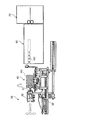
- the card transfer mechanism 30 includes a card holding part 31, a support part 32, a horizontal rotation shaft 33, an upper and lower guide part 34, and a front and rear guide part 35.
- the card holding unit 31 is formed to be rotatable about the horizontal rotation shaft 33 and holds the rewrite card RC.
- the support part 32 is formed so as to support the card holding part 31 above the card position regulating mechanism 40.
- the support portion 32 is further formed to move up and down by an up and down guide portion 34 and to be movable back and forth by a front and back guide portion 35.
- the horizontal rotation shaft 33 has an axis substantially parallel to the apparatus installation surface, and is formed to be rotatable around the same axis.
- the vertical guide portion 34 is formed so as to guide the support portion 32 in the vertical direction of FIG.
- the front / rear guide part 35 is formed to guide the support part 32 in the front / rear direction of FIG. 5, that is, in the forward / backward direction with respect to the card printing mechanism 50.
- the card transfer mechanism 30 operates as follows. As shown in FIGS. 3 and 5, the card holding unit 31 receives the pre-printing rewrite card RC held by the card holding units 22 a and 22 b of the handling mechanism 20 in an inclined state. The card holding unit 31 is driven and rotated about the horizontal rotation shaft 33 to bring the rewritable card RC into a horizontal state, and then the support unit 32 is lowered by the driven upper and lower guide units 34, whereby the rewritable card is driven. RC is set in the card position adjusting mechanism 40.
- the second card sensor 42 (FIG. 6) of the card position regulating mechanism 40 senses the pre-printing rewrite card RC.
- the second card sensor 42 transmits a card detection signal to the device controller 5.
- the device controller 5 issues a command to the card transfer mechanism 30.
- the apparatus controller 5 also reverses the front and back of the pre-print rewrite card RC by the card transfer mechanism 30 when necessary.
- the card holding unit 31 releases the holding of the pre-print rewrite card RC, and the pre-print rewrite card RC is positioned by the card position adjusting mechanism 40. After holding the pre-printed rewrite card RC whose position has been corrected by the card holding unit 31, the card position correction is released.
- the support unit 32 In the state where the card holding unit 31 holds the rewrite card RC before printing horizontally, the support unit 32 is raised by the driven vertical guide unit 34. Furthermore, the support part 32 advances toward the card printing mechanism 50 by the driven front and rear guide part 35. After the card holding unit 31 releases the holding of the pre-print rewrite card RC, the pre-print rewrite card RC is inserted into the card printing mechanism 50 as indicated by a virtual line in FIG.
- the card printing mechanism 50 ejects the card, and the card holding unit 31 holds the rewrite card RC after printing.
- the support portion 32 is retracted by the driven front / rear guide portion 35 to remove the rewritable card RC from the card printing mechanism 50 after printing.
- the support portion 32 is lowered by the driven vertical guide portion 34, and sets the rewrite card RC after printing to the card position adjusting mechanism 40.
- the card holding unit 31 releases the holding of the rewritable card RC after printing, and the rewritable card RC after printing is positioned by the card position regulating mechanism 40. After the rewritten post-printing rewritten card RC is held by the card holding unit 31, the card position correction is released.
- the card holding unit 31 is driven and rotated around the horizontal rotation shaft 33 to hold the rewritable card RC after printing in an inclined state as shown in FIG. 4 from the horizontal state, and to the card holding units 22a and 22b of the handling mechanism 20. hand over.
- the front / back direction when the rewritten card RC is passed to the handling mechanism 20 and the front / back direction of the pre-printed rewrite card RC when inserted into the card printing mechanism 50 are determined in advance.
- the card transfer mechanism 30 rotates the horizontal rotation shaft 33 based on information on the front and back directions determined in advance and a signal from the second card sensor 42, and reverses the rewrite card RC as necessary.
- the card position adjusting mechanism 40 includes first position adjusting parts 41a and 41a, second position adjusting parts 41b and 41b, and a second card sensor.
- the first position setting parts 41a and 41a are arranged in a plan view so as to sandwich the corners of the rewrite card RC placed along the substantially horizontal direction. Position in the left / right and front / rear direction. Furthermore, the second position restricting portions 41b and 41b perform the left and right positioning of the rewrite card RC in a plane so as to sandwich the long side of the rewrite card RC.
- the second card sensor 42 is a photoelectric sensor having a light projecting / receiving element.
- a three color (red, blue, green) LED light source is used for the light projecting element, and the detection object is irradiated with spot light.
- This is a color sensor that performs color discrimination by analyzing a color component of light received by reflection from the light.
- the second card sensor 42 senses the rewrite card RC and transmits a signal to the device controller 5.
- the device control unit 5 determines the presence and front / back direction of the rewrite card RC from the transmitted signal.
- the second card sensor 42 is a CCD camera, and the presence and the front / back direction of the rewrite card RC may be determined by recognizing the image obtained by the device control unit 5.
- Card printing mechanism 50 The card printing mechanism 50 prints predetermined information on the rewrite card RC based on the patient identification information in accordance with a command from the apparatus control unit 5, and creates a rewritten card RC after printing.
- the card printing mechanism 50 includes, for example, a heat energy application unit such as a heat roller or a thermal head inside, and applies heat energy at a predetermined temperature to the information display surface of the inserted rewrite card RC, thereby providing an information display surface. It is a device that erases and writes information. Such a rewritable card printing apparatus is well known, and therefore, detailed description thereof is omitted.
- Card stocker 70 The card stocker 70 stores a plurality of rewrite cards RC.
- the device controller 5 outputs a rewrite card RC supply request to the management device 310, and the management device 310 issues a rewrite card RC supply request command to the card printing mechanism 50 in response to the request.
- the card stocker 70 supplies the rewrite card RC to the card printing mechanism 50.
- the card stocker 70 supplies the pre-printing rewrite card RC1 attached to the tray T1 that is transported first after the medicine dispensing apparatus 1 starts operating. Furthermore, when the card stocker 70 cannot acquire the pre-print rewrite card RC2 from the tray T1 or the tray T2 or fails to acquire it, the pre-print rewrite card RC2 attached to the tray T2 to be transported next time. Supply.
- the label / prescription issuing unit 6 includes a label printing mechanism 61 that prints tray labels and application labels, a prescription printing mechanism 62 that prints prescriptions, and an input mechanism that inputs the printed prescriptions and labels. 63.
- the label printing mechanism 61 is arranged above the card processing unit 10 and normally issues an application label that describes drug application information. When an error occurs in the card processing unit 10, it displays patient identification information in addition to the application label. Print a tray label to replace the rewritten card RC.
- the prescription printing mechanism 62 is disposed above the label printing mechanism 61 as shown in FIG.
- the prescription printing mechanism 62 issues a prescription corresponding to the patient's prescription information to each tray T.
- the input mechanism 63 moves the pocket portion 63a up and down.
- the pocket portion 63a receives the prescription from the prescription printing mechanism 62, receives the application label from the label printing mechanism 61, and puts it into the tray T.
- the pocket portion 63a also moves up and down in response to a command from the device control unit 5 that has received an error signal, as will be described later, and a tray label printed with patient identification information from the label printing mechanism 61 in the same manner as the rewrite card RC. Receive it and put it in the tray T.
- Label printing mechanism 61 Usually, the label printing mechanism 61 prints the applied label in response to a print command from the management device 310. After printing, the applied label is primarily held in the label pocket 61a from the discharge port of the label printing mechanism 61, and then placed in the pocket portion 63a of the loading mechanism 63. The application label is supplied to all trays T.
- the label pocket 61a temporarily holds an application label issued while the pocket portion 63a of the loading mechanism 63 receives a prescription from the prescription printing mechanism 62.
- the label printing mechanism 61 prints a tray label used in place of the rewrite card RC in response to the occurrence of an error in the card processing unit 10 in addition to the normal issuance of an application label.
- the label printing mechanism 61 in this case operates in response to a tray label issuance command from the management device 310, as will be described later.
- the tray label is manually attached to the tray T at the time of drug inspection after the tray T is carried out.
- the tray label is printed with patient identification information.
- both labels are primarily held in the label pocket 61 a from the discharge port of the label printing mechanism 61. Thereafter, both labels are put into the pocket portion 63 a of the input mechanism 63 and supplied to the tray T.
- the application label is supplied to the tray T by the same process as described above. During this time, the printing of the tray label is completed, and thereafter, it is primarily held in the label pocket 61a from the discharge port of the label printing mechanism 61. Thereafter, the tray label is put in the pocket portion 63 a of the input mechanism 63 and supplied to the tray T.
- Prescription printing mechanism 62 The prescription printing mechanism 62 issues a prescription sheet on which patient prescription information is printed. The issued prescription is put into the pocket portion 63a of the loading mechanism 63 and is loaded into the trays T of all patients.
- the throwing mechanism 63 has a guide part G extending in the vertical direction in FIG. 7 and a pocket part 63a that moves up and down along the guide part G.
- the pocket portion 63a of the loading mechanism 63 is disposed so as to face the label printing mechanism 61 and the prescription printing mechanism 62, and moves up and down along the guide portion G by a driving source such as a motor.
- the pocket portion 63a receives the label and the prescription from the label printing mechanism 61 and the prescription printing mechanism 62, and puts them into the tray T.
- FIG. 8 is a control block diagram showing the relationship among the device control unit 5, the card processing unit 10, the label / prescription issuing unit 6, and the management device 310 of the medicine dispensing device 1.
- the device control unit 5 controls the operation of each mechanism of the card processing unit 10 and the label / prescription issuing unit 6.
- the device control unit 5 commands the operation based on a predetermined condition judgment, particularly for the label printing mechanism 61 and the loading mechanism 63 of the label / prescription issuing unit 6.
- the device control unit 5 receives the rewrite card from the sensor of the card processing unit 10 (the first card sensor 26 of the handling mechanism 20, the third card sensor 27 and the second card sensor 42 of the card position regulating mechanism 40). A signal for sensing RC is received. The apparatus control unit 5 also receives an error signal from the card processing unit 10 and transmits a rewrite card RC supply request and a tray label print request to the management apparatus 310.
- the management apparatus 310 receives patient identification information, medicine application information, prescription information, and the like from the electronic medical chart system 300 (FIG. 1), and issues a command to the medicine dispensing apparatus 1 based on these information.
- the management device 310 causes the card stocker 70 to supply the rewrite card RC via the card printing mechanism 50 in response to the rewrite card RC supply request from the device control unit 5.
- the management device 310 also outputs a print command for the rewrite card RC to the card printing mechanism 50.
- the management device 310 outputs an operation command to the label printing mechanism 61 in response to a tray label printing request from the device control unit 5 to print the tray label.
- the management device 310 Normally, the management device 310 outputs an operation command for printing the applied label to the label printing mechanism 61. Further, the management device 310 outputs an operation command for printing a prescription corresponding to the prescription information to the prescription printing mechanism 62.
- the management device 310 transmits and receives barcode information and patient identification information (link information) to and from the device control unit 5. Specifically, the management device 310 receives the barcode information (tray identification information) of the tray T read by the barcode reader (not shown) of the medicine dispensing unit 3 via the device control unit 5. The management apparatus 310 generates link information that associates the barcode information with the patient identification information and the drug information based on the patient prescription information, and transmits the link information to the apparatus control unit 5. The device control unit 5 stores the link information in the memory. The device control unit 5 also transmits a medicine dispensing instruction to the medicine dispensing unit 3.
- the device control unit 5 of the medicine dispensing device 1 starts conveying the tray T1 in response to the dispensing start signal.
- the device control unit 5 issues a card supply request to the management device 310, and the management device 310 sends the rewrite card RC 1 to the card printing mechanism 50 to the card stocker 70 via the card printing mechanism 50 of the card processing unit 10. Issue a supply command.
- printing of the rewrite card RC1 attached to the tray T1 that is first transported after the medicine dispensing device 1 is activated can be started in advance.
- the apparatus controller 5 also receives a signal for detecting the rewrite card RC from the first and third card sensors 26 and 27 of the handling mechanism 20 and the second card sensor 42 of the card position regulating mechanism 40.
- the device control unit 5 determines that there is no pre-print rewrite card RC because it has not received these signals, issues a card supply request to the management device 310, and the management device 310 prints the card in the card processing unit 10.
- a command for supplying the rewrite card RC to the card printing mechanism 50 is issued to the card stocker 70 via the mechanism 50. With this control, the card can be stably supplied even in an unexpected situation such as when a new rewrite card RC cannot be acquired from the tray T or when acquisition fails.
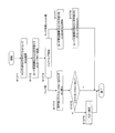
- FIG. 9A and FIG. 9B show that the rewrite card RC2 before printing is acquired from the tray T1 that is loaded first and printed by the payout start signal from the management device 310. At substantially the same time, a series of processing flow is shown in which the printed rewrite card RC1 is attached to the tray T1, and the printed rewrite card RC2 is attached to the subsequently conveyed tray T2.
- the rewrite card RC1 (first card) attached to the tray T1 (first transporter) that is first carried in is transferred from the card stocker 70 while the tray T1 is being transported to the card processing unit 10. Supplied and printed.
- the rewrite card RC2 (second card) before printing, which is mounted in advance on each tray T, patient identification information corresponding to the medicine dispensed to the subsequent tray T2 (second transporter) is printed. Will be. That is, each tray T is attached with the post-print rewrite card RC on which the identification information of the patient corresponding to the medicine dispensed is already printed at the same time that the pre-print rewrite card RC that has been attached is extracted. . As a result, the waiting time of the tray T is shortened, and the conveyance efficiency is improved.
- the processing of the tray T1 and the processing of the tray T2 following the tray T1 are described.
- the tray T2 includes all the trays T following the tray T1, and both It shall be processed similarly.
- the tray T1 and the tray T2 are sequentially conveyed and processed in parallel.
- the following processing flow is an example, and the present invention is not limited to this.
- the tray T1 is processed as follows.
- drug information used for drug dispensing is created based on patient prescription information.
- Step S101 In response to a dispensing start signal from the management device 310, the device controller 5 of the medicine dispensing device 1 starts conveying the tray T1. At the same time, the device control unit 5 issues a card supply request to the management device 310, and the management device 310 sends the rewrite card RC 1 to the card printing mechanism 50 to the card stocker 70 via the card printing mechanism 50 of the card processing unit 10. Issue a supply command.
- Step S102 The tray T1 arrives at the medicine dispensing unit 3 from the tray supply unit 2.
- Step S103 The barcode information (tray identification information) of the tray T1 is read by the barcode reader (not shown) of the medicine dispensing unit 3 and transmitted to the management device 310.
- Step S104 In the management device 310, link information that associates the barcode information with the medicine information is created and transmitted to the device control unit 5 of the medicine dispensing device 1, and the device control unit 5 links to its own memory. Store information.
- Step S105 The medicines are sequentially dispensed to the tray T1 based on the medicine information of the patient.
- Step S106 When the medicine dispensing immediately before the card processing unit 10 is completed, the barcode on the tray T1 is read by the barcode reader 71 and transmitted to the management device 310. In addition, a supply command for the rewrite card RC1 is issued.
- Step S107 The card printing data is created based on the patient identification information corresponding to the barcode information in the management device 310, and the card printing data is output from the management device 310 to the card printing mechanism 50, and the rewrite card RC. Is printed.
- Step S108 On the other hand, the rewritten card RC1 after printing is extracted from the card printing mechanism 50 by the card transfer mechanism 30.
- the post-printing rewrite card RC1 is subjected to position regulation by the card position regulation mechanism 40 after the card transfer mechanism 30 releases the holding of the rewrite card RC1.
- Step S109 Card replacement processing is performed by the card processing unit 10 (steps S1071 to S1078), and the rewritable card RC1 after printing is attached to the tray T1.
- Step S110 After printing, the tray T1 to which the rewrite card RC1 is attached is carried out.
- the tray T2 carried in after the tray T1 is processed as follows, as shown in FIG.
- Step S201 The tray T2 is carried into the medicine dispensing unit 3 from the tray supply unit 2.
- Step S202 The barcode information (tray identification information) of the tray T2 is read by the barcode reader (not shown) of the medicine dispensing unit 3 and transmitted to the management device 310.
- Step S203 In the management apparatus 310, link information that associates the barcode information (tray identification information) with the medicine information is created and transmitted to the apparatus control section 5 of the medicine dispensing apparatus 1, and the apparatus control section 5 Store link information in its own memory.
- Step S204 The medicines are sequentially dispensed to the tray T2 based on the medicine information of the patient.
- Step S205 In the medicine dispensing unit 3, when the medicine dispensing immediately before the card processing unit 10 is completed, the barcode information on the tray T2 is read by the barcode reader 71 and transmitted to the management device 310. At this time, a command for issuing the rewrite card RC2 is issued.
- Step S206 In the management device 310, card printing data is created based on the patient identification information corresponding to the barcode information.
- Step S207 The card processing unit 10 issues a rewrite card RC2 attached to the tray T2 (steps S1001 to S1011).
- Step S208 Card replacement processing is performed by the card processing unit 10, and the rewritten card RC2 after printing is attached to the tray T2. This card replacement process is performed in the same manner as the card replacement process in steps S1071 to S1078 described later.
- Step S209 After printing, the tray T2 to which the rewrite card RC2 is attached is carried out.
- FIG. 10 shows a flow of card replacement processing by the card processing unit 10.
- Step S1071 The rewrite card RC2 before printing in the card holder 4 of the tray T1 is gripped by one card gripping portion 22a of the handling mechanism 20 of the card processing unit 10.
- Step S1072 At the same time, the post-printing rewrite card RC1 held in the card transfer mechanism 30 is gripped by the other card gripping portion 22b of the handling mechanism 20.
- Step S1073 The handling mechanism 20 rotates 180 degrees.
- the card gripping portion 22a moves to the card position regulating mechanism 40 side, and the card gripping portion 22b moves to the tray T1 side.
- Step S1074 On the tray T1 side, the rewritable card RC1 after printing is inserted into the card holder 4 of the tray T1 by the card gripping portion 22b.
- Step S1075 The rewrite card RC1 is detected by the first card sensor 26 and transmitted to the device control unit 5. If the rewrite card RC1 is not detected, the process proceeds to step S1076.
- Step S1076 The apparatus control unit 5 transmits an error signal.
- the case where the error signal is transmitted is, for example, a case where the post-print rewrite card RC1 cannot be attached to the tray T1 by the handling mechanism 20.
- the apparatus control unit 5 causes the label printing mechanism 61 to issue a label instead of the rewrite card RC1 via the management apparatus 310.
- Step S1077 On the other hand, on the card position regulating mechanism 40 side, the pre-print rewrite card RC2 is delivered from the card gripping portion 22a to the card transfer mechanism 30.
- Step S1078 The rewrite card RC2 before printing is set in the card position adjusting mechanism 40 by the card transfer mechanism 30.
- FIG. 11 shows a flow of card issuance processing by the card processing unit 10.
- Step S1001 When the second card sensor 42 of the card position adjusting mechanism 40 senses the rewrite card RC2 set in the card position adjusting mechanism 40, a signal is transmitted to the device controller 5. If the rewrite card RC2 is detected, the process proceeds to step S1002, and if the rewrite card RC2 is not detected, the process proceeds to step S1006.
- Step S1002 The device controller 5 further determines the front and back of the rewrite card RC2 from the signal from the second card sensor 42. If the front / back direction of the rewrite card RC2 is not as prescribed, the process proceeds to step S1003, and if it is as prescribed, the process proceeds to step S1004.
- Step S1003 The card transfer mechanism 30 reverses the front and back of the rewrite card RC2, and sets the card position adjusting mechanism 40 again.
- Step S1004 After the card transfer mechanism 30 releases the holding of the rewrite card RC2, the position of the rewrite card RC2 is regulated by the card position regulating mechanism 40.
- Step S1005 The pre-printing rewrite card RC2 whose position is regulated is gripped by the card transfer mechanism 30 and inserted into the card printing mechanism 50.
- Step S1006 On the other hand, if the rewrite card RC2 is not detected by the second card sensor 42, the device control unit 5 outputs a supply request for the rewrite card RC to the management device 310.
- the management device 310 issues a rewrite card RC supply command to the card printing mechanism 50 in response to the request. In response to this command, the card stocker 70 supplies a spare rewrite card RC to the card printing mechanism 50.
- Step S1007 If the spare rewrite card RC2 cannot be supplied from the card stocker 70, the process proceeds to step S1008, and if the rewrite card RC2 is supplied, the process proceeds to step 1009.
- Step S1008 The card processing unit 10 transmits an error signal to the device control unit 5.
- the case where the error signal is transmitted is a case where the rewrite card RC is not supplied from the card stocker 70.
- the apparatus control unit 5 Upon receiving this error signal, the apparatus control unit 5 causes the label printing mechanism 61 to issue a tray label instead of the rewrite card RC2 via the management apparatus 310.
- Step S1009 The card printing mechanism 50 prints the card printing data created by the management device 310 on the rewrite card RC2.
- Step S1010 After the printing, the rewrite card RC2 is extracted from the card printing mechanism 50 by the card transfer mechanism 30.
- Step S1011 After the card transfer mechanism 30 releases the holding of the rewritten card RC2 after printing, the position of the rewritten card RC2 after printing is regulated by the card position regulating mechanism 40. Thereafter, the rewritable card RC2 after printing is transferred to the handling mechanism 20 by the card transfer mechanism 30 (proceeds to step S1072 in FIG. 10).
- the rewrite card RC1 to be attached to the tray T1 that has been transported first is written with information necessary until the tray T1 is transported.
- the rewrite card RC1 can be efficiently attached to the tray T1.
- the rewrite card RC2 acquired from the tray T1 is acquired, necessary information is written, and the tray T2 is prepared in advance until the tray T2 is transported, thereby efficiently.
- the rewrite card RC2 can be attached.
- the rewrite card RC2 acquired from the previously conveyed tray T2 can be efficiently attached to the third and subsequent trays T2.
- the waiting time of the transporter when the rewrite card RC is attached is shortened, the transport efficiency of the transporter is improved, and as a result, the medicine dispensing efficiency can be improved.
- the rewrite card RC2 is obtained from the tray T1 and printed almost simultaneously with the rewrite card RC1 attached to the previously transported tray T1. Similarly, when the rewritable card RC2 after printing is attached to the tray T2 conveyed after the tray T1, another rewritable card RC2, which is the next card, is obtained from the tray T2, printed, and printed. Mount on the tray T2. Thereby, the rewrite card RC can be obtained efficiently and reliably.
- a card stocker 70 that stores and supplies a plurality of cards is provided as a supply source of a new rewrite card RC. Accordingly, since the rewrite card RC1 can be prepared and prepared in advance for the tray T1 that is transported first, the waiting time of the tray T1 can be shortened. In addition, since the rewrite card RC2 can be supplied from the card stocker 70 in an emergency in which a new rewrite card RC2 cannot be obtained, a new card supply source can be reserved in advance and a shortage of cards can be prevented.
- the rewrite card RC is a rewrite card
- the rewrite card RC is used as it is as the pre-print rewrite card RC at the next payout. it can.
- the rewrite card RC1 attached to the tray T1 that is transported first is supplied from the card stocker 70.
- the rewrite card RC1 may be set in advance in the handling mechanism 20, the card transfer mechanism 30, the card position regulating mechanism 40, or the like, and supplied from these mechanisms.
- the tray T2 to which the rewrite card RC2 is attached is attached to the tray T2 next to the tray T2 that has acquired the rewrite card RC2.
- the rewrite card RC2 may be attached to the tray T2 transported two times later or the tray T2 transported later.
- the interval from when the rewrite card RC2 is acquired to when it is attached can be determined flexibly according to the processing time in the card printing mechanism 50, the transport speed of the tray T, and the like.
- control unit 5 and the management device 310 are provided as the control unit, but the present invention is not limited to this mode. Some or all of the respective controls may be performed by the other device, or a single device may be provided separately or integrally to perform all the controls.
- the positions of the first card sensor 26 and the third card sensor 27 of the handling mechanism 20 of the card processing unit 10 and the position of the second card sensor 42 of the card position adjusting mechanism 40 are not limited to those of the above embodiment.
- the number of card sensors may be one or three or more. Further, the device control unit 5 may determine the presence / absence of the rewrite card RC before printing or the rewrite card RC after printing based on signals from a plurality of card sensors at different positions.
- the present invention is useful as a medicine dispensing apparatus and a medicine dispensing method because it has the effect of improving the efficiency of medicine dispensing by shortening the waiting time of the transporter.
Landscapes
- General Physics & Mathematics (AREA)
- Physics & Mathematics (AREA)
- Health & Medical Sciences (AREA)
- Engineering & Computer Science (AREA)
- Medical Informatics (AREA)
- Public Health (AREA)
- Primary Health Care (AREA)
- Epidemiology (AREA)
- General Health & Medical Sciences (AREA)
- Chemical & Material Sciences (AREA)
- Medicinal Chemistry (AREA)
- Bioinformatics & Cheminformatics (AREA)
- Medical Preparation Storing Or Oral Administration Devices (AREA)
- Basic Packing Technique (AREA)
Priority Applications (2)
| Application Number | Priority Date | Filing Date | Title |
|---|---|---|---|
| US13/119,354 US8650838B2 (en) | 2008-09-19 | 2009-09-14 | Drug delivery device and drug delivery method |
| EP09814271.4A EP2327389A4 (en) | 2008-09-19 | 2009-09-14 | PHARMACEUTICAL DISPENSER AND METHOD FOR THE DISPOSAL OF PHARMACEUTICALS |
Applications Claiming Priority (2)
| Application Number | Priority Date | Filing Date | Title |
|---|---|---|---|
| JP2008-241836 | 2008-09-19 | ||
| JP2008241836A JP5350724B2 (ja) | 2008-09-19 | 2008-09-19 | 薬剤払出装置および薬剤払出方法 |
Publications (1)
| Publication Number | Publication Date |
|---|---|
| WO2010032426A1 true WO2010032426A1 (ja) | 2010-03-25 |
Family
ID=42039276
Family Applications (1)
| Application Number | Title | Priority Date | Filing Date |
|---|---|---|---|
| PCT/JP2009/004578 Ceased WO2010032426A1 (ja) | 2008-09-19 | 2009-09-14 | 薬剤払出装置および薬剤払出方法 |
Country Status (4)
| Country | Link |
|---|---|
| US (1) | US8650838B2 (enExample) |
| EP (1) | EP2327389A4 (enExample) |
| JP (1) | JP5350724B2 (enExample) |
| WO (1) | WO2010032426A1 (enExample) |
Cited By (1)
| Publication number | Priority date | Publication date | Assignee | Title |
|---|---|---|---|---|
| TWI856138B (zh) * | 2019-07-23 | 2024-09-21 | 日商湯山製作所股份有限公司 | 卡片安裝裝置、卡片裝卸裝置、卡片夾以及托盤輸送裝置 |
Families Citing this family (6)
| Publication number | Priority date | Publication date | Assignee | Title |
|---|---|---|---|---|
| JP6690541B2 (ja) * | 2014-09-24 | 2020-04-28 | 株式会社湯山製作所 | 薬剤払出装置 |
| CN105667846A (zh) * | 2016-03-21 | 2016-06-15 | 天津森雅医疗设备科技有限公司 | 一种摆药设备及其摆药方法 |
| CN105644819A (zh) * | 2016-03-21 | 2016-06-08 | 天津森雅医疗设备科技有限公司 | 一种派药系统及其派药方法 |
| GB2561347A (en) * | 2017-04-07 | 2018-10-17 | Medi Clear Ltd | Methods and apparatus for automatically filling dispensing containers |
| EP3636240A1 (en) * | 2018-10-09 | 2020-04-15 | MEDI-Clear Ltd | Methods and apparatus for automatically filling dispensing containers |
| US20200115074A1 (en) * | 2018-10-10 | 2020-04-16 | Medi-Clear Ltd | Methods and Apparatus for Automatically Filling Dispensing Containers |
Citations (4)
| Publication number | Priority date | Publication date | Assignee | Title |
|---|---|---|---|---|
| JPH06127184A (ja) * | 1992-10-21 | 1994-05-10 | Ricoh Co Ltd | カードの処理方法 |
| JPH0951922A (ja) * | 1995-06-09 | 1997-02-25 | Yuyama Seisakusho:Kk | 医薬品類の搬送方法及び装置 |
| JP2005161736A (ja) * | 2003-12-04 | 2005-06-23 | Hitachi Omron Terminal Solutions Corp | カード取扱装置 |
| JP2005279268A (ja) * | 2005-03-22 | 2005-10-13 | Yuyama Manufacturing Co Ltd | 薬剤払出装置 |
Family Cites Families (10)
| Publication number | Priority date | Publication date | Assignee | Title |
|---|---|---|---|---|
| US5604692A (en) * | 1994-07-19 | 1997-02-18 | Yuyama; Shoji | Method of controlling drug conveyor system |
| US5988858A (en) * | 1995-06-09 | 1999-11-23 | Kabushiki Kaisha Yuyama Seiksakusho | Method and apparatus for delivering drugs |
| JPH10198736A (ja) * | 1997-01-13 | 1998-07-31 | Yuyama Seisakusho:Kk | 医薬品処理システム |
| JP3737697B2 (ja) | 2000-11-30 | 2006-01-18 | 株式会社湯山製作所 | 搬器表示部材の書込み装置 |
| US8025314B2 (en) * | 2002-05-15 | 2011-09-27 | Target Brands, Inc. | Medication packaging and labeling system |
| US6892512B2 (en) * | 2002-08-07 | 2005-05-17 | Medco Health Solutions, Inc. | Automated prescription filling system/method with automated labeling and packaging system/method automated order consolidation system/method |
| WO2005105619A1 (ja) * | 2004-04-30 | 2005-11-10 | Yuyama Mfg. Co., Ltd. | 薬品供給システム |
| JP4432717B2 (ja) | 2004-10-12 | 2010-03-17 | パナソニック株式会社 | 注射薬自動払出装置 |
| JP4679168B2 (ja) * | 2004-11-08 | 2011-04-27 | 株式会社湯山製作所 | 脱着装置、表示変更装置、並びに、投薬システム |
| US7912578B1 (en) * | 2006-06-27 | 2011-03-22 | Frankel Mark E | System and method for conveying pharmaceuticals from an automated machine |
-
2008
- 2008-09-19 JP JP2008241836A patent/JP5350724B2/ja active Active
-
2009
- 2009-09-14 WO PCT/JP2009/004578 patent/WO2010032426A1/ja not_active Ceased
- 2009-09-14 EP EP09814271.4A patent/EP2327389A4/en not_active Withdrawn
- 2009-09-14 US US13/119,354 patent/US8650838B2/en active Active
Patent Citations (4)
| Publication number | Priority date | Publication date | Assignee | Title |
|---|---|---|---|---|
| JPH06127184A (ja) * | 1992-10-21 | 1994-05-10 | Ricoh Co Ltd | カードの処理方法 |
| JPH0951922A (ja) * | 1995-06-09 | 1997-02-25 | Yuyama Seisakusho:Kk | 医薬品類の搬送方法及び装置 |
| JP2005161736A (ja) * | 2003-12-04 | 2005-06-23 | Hitachi Omron Terminal Solutions Corp | カード取扱装置 |
| JP2005279268A (ja) * | 2005-03-22 | 2005-10-13 | Yuyama Manufacturing Co Ltd | 薬剤払出装置 |
Cited By (1)
| Publication number | Priority date | Publication date | Assignee | Title |
|---|---|---|---|---|
| TWI856138B (zh) * | 2019-07-23 | 2024-09-21 | 日商湯山製作所股份有限公司 | 卡片安裝裝置、卡片裝卸裝置、卡片夾以及托盤輸送裝置 |
Also Published As
| Publication number | Publication date |
|---|---|
| US8650838B2 (en) | 2014-02-18 |
| EP2327389A1 (en) | 2011-06-01 |
| JP5350724B2 (ja) | 2013-11-27 |
| JP2010069159A (ja) | 2010-04-02 |
| US20110162323A1 (en) | 2011-07-07 |
| EP2327389A4 (en) | 2014-04-23 |
Similar Documents
| Publication | Publication Date | Title |
|---|---|---|
| JP5350724B2 (ja) | 薬剤払出装置および薬剤払出方法 | |
| CN103619252B (zh) | 采血管自动准备系统 | |
| AU2003269946B2 (en) | System for labeling a medicine container with a folded label | |
| JP2009036643A (ja) | ラックへの試験管投入パターンの制御装置 | |
| USRE43549E1 (en) | Writing device for display members on drug carrier | |
| JP2834595B2 (ja) | 検体採取用試験管準備方法及び装置 | |
| CN101971221A (zh) | 用于配药的自动标签校验系统和方法 | |
| WO2018188182A1 (zh) | 采血管准备装置 | |
| JP5807239B2 (ja) | 薬品自動払出装置 | |
| JP5208640B2 (ja) | 薬剤払出装置および薬剤払出方法 | |
| JP2010069162A (ja) | リライト装置 | |
| JP2002102210A (ja) | 採血管準備装置 | |
| JP2010069173A (ja) | カード処理装置 | |
| JP2009036642A (ja) | 試験管用ラックの制御装置 | |
| JP4966798B2 (ja) | 採血管自動準備装置 | |
| JP2005132565A (ja) | 薬剤払出機用印刷装置 | |
| JP2005279268A (ja) | 薬剤払出装置 | |
| HK1195472B (en) | Automatic preparation system for blood collection tube |
Legal Events
| Date | Code | Title | Description |
|---|---|---|---|
| 121 | Ep: the epo has been informed by wipo that ep was designated in this application |
Ref document number: 09814271 Country of ref document: EP Kind code of ref document: A1 |
|
| WWE | Wipo information: entry into national phase |
Ref document number: 2009814271 Country of ref document: EP |
|
| WWE | Wipo information: entry into national phase |
Ref document number: 13119354 Country of ref document: US |
|
| NENP | Non-entry into the national phase |
Ref country code: DE |