WO2010029613A1 - ホログラム装置及び記録方法 - Google Patents
ホログラム装置及び記録方法 Download PDFInfo
- Publication number
- WO2010029613A1 WO2010029613A1 PCT/JP2008/066242 JP2008066242W WO2010029613A1 WO 2010029613 A1 WO2010029613 A1 WO 2010029613A1 JP 2008066242 W JP2008066242 W JP 2008066242W WO 2010029613 A1 WO2010029613 A1 WO 2010029613A1
- Authority
- WO
- WIPO (PCT)
- Prior art keywords
- recording
- address
- page
- angle
- recorded
- Prior art date
- Legal status (The legal status is an assumption and is not a legal conclusion. Google has not performed a legal analysis and makes no representation as to the accuracy of the status listed.)
- Ceased
Links
Images










Classifications
-
- G—PHYSICS
- G11—INFORMATION STORAGE
- G11B—INFORMATION STORAGE BASED ON RELATIVE MOVEMENT BETWEEN RECORD CARRIER AND TRANSDUCER
- G11B7/00—Recording or reproducing by optical means, e.g. recording using a thermal beam of optical radiation by modifying optical properties or the physical structure, reproducing using an optical beam at lower power by sensing optical properties; Record carriers therefor
- G11B7/007—Arrangement of the information on the record carrier, e.g. form of tracks, actual track shape, e.g. wobbled, or cross-section, e.g. v-shaped; Sequential information structures, e.g. sectoring or header formats within a track
- G11B7/00772—Arrangement of the information on the record carrier, e.g. form of tracks, actual track shape, e.g. wobbled, or cross-section, e.g. v-shaped; Sequential information structures, e.g. sectoring or header formats within a track on record carriers storing information in the form of optical interference patterns, e.g. holograms
- G11B7/00781—Auxiliary information, e.g. index marks, address marks, pre-pits, gray codes
-
- G—PHYSICS
- G11—INFORMATION STORAGE
- G11B—INFORMATION STORAGE BASED ON RELATIVE MOVEMENT BETWEEN RECORD CARRIER AND TRANSDUCER
- G11B7/00—Recording or reproducing by optical means, e.g. recording using a thermal beam of optical radiation by modifying optical properties or the physical structure, reproducing using an optical beam at lower power by sensing optical properties; Record carriers therefor
- G11B7/08—Disposition or mounting of heads or light sources relatively to record carriers
- G11B7/083—Disposition or mounting of heads or light sources relatively to record carriers relative to record carriers storing information in the form of optical interference patterns, e.g. holograms
-
- G—PHYSICS
- G03—PHOTOGRAPHY; CINEMATOGRAPHY; ANALOGOUS TECHNIQUES USING WAVES OTHER THAN OPTICAL WAVES; ELECTROGRAPHY; HOLOGRAPHY
- G03H—HOLOGRAPHIC PROCESSES OR APPARATUS
- G03H1/00—Holographic processes or apparatus using light, infrared or ultraviolet waves for obtaining holograms or for obtaining an image from them; Details peculiar thereto
- G03H1/26—Processes or apparatus specially adapted to produce multiple sub- holograms or to obtain images from them, e.g. multicolour technique
- G03H1/2645—Multiplexing processes, e.g. aperture, shift, or wavefront multiplexing
- G03H1/265—Angle multiplexing; Multichannel holograms
-
- G—PHYSICS
- G11—INFORMATION STORAGE
- G11B—INFORMATION STORAGE BASED ON RELATIVE MOVEMENT BETWEEN RECORD CARRIER AND TRANSDUCER
- G11B7/00—Recording or reproducing by optical means, e.g. recording using a thermal beam of optical radiation by modifying optical properties or the physical structure, reproducing using an optical beam at lower power by sensing optical properties; Record carriers therefor
- G11B7/007—Arrangement of the information on the record carrier, e.g. form of tracks, actual track shape, e.g. wobbled, or cross-section, e.g. v-shaped; Sequential information structures, e.g. sectoring or header formats within a track
- G11B7/00772—Arrangement of the information on the record carrier, e.g. form of tracks, actual track shape, e.g. wobbled, or cross-section, e.g. v-shaped; Sequential information structures, e.g. sectoring or header formats within a track on record carriers storing information in the form of optical interference patterns, e.g. holograms
Definitions
- the present invention relates to a hologram apparatus, a recording method, and a reproducing method for hologram angle multiplex recording of a hologram recording medium (hereinafter simply referred to as a recording medium) capable of recording or reproducing information by irradiating a light beam such as an optical disk or an optical card.
- a recording medium capable of recording or reproducing information by irradiating a light beam such as an optical disk or an optical card.
- the present invention relates to a method for recording data defining address information of an angle multiplexed hologram group (book).
- a recording medium capable of recording two-dimensional data obtained by converting data to be recorded such as images and text, address information, and the like into a two-dimensional pixel pattern (page) with high density and its hologram device have attracted attention.
- the feature of this hologram is that the wavefront of signal light carrying two-dimensional data is recorded on a recording medium using an optical interference pattern with coherent reference light as a diffraction grating (hologram). That is, the optical paths of the reference light and the signal light are spatially separated from each other, and the two are crossed in the recording medium by the interference means to record two-dimensional data as a hologram.
- the angle at which the reference light intersects the signal light within the recording medium (the crossing angle, and the incidence angle when the recording medium surface is used as a reference when the signal light is irradiated perpendicularly to the surface of the recording medium)
- the holograms (pages) that are different for each crossing angle can be recorded in the same unit recording area by angle multiplex recording.
- the recording medium 2 When performing angle multiplex recording in which a plurality of holograms are recorded in the same unit recording area, the image is stopped at the intersection angle ⁇ 1 for the time required for recording, then changed to the intersection angle ⁇ 2 and stopped, and moved to the intersection angle ⁇ 3 and stopped. Then, means for repeating the operation of sequentially writing the holograms HG1 to HGm, that is, an optical deflecting device is required.
- Each page includes information (page address information) for specifying the page corresponding to the incident angle of the reference light. In general, the interval of crossing angles, that is, the angle interval ⁇ is kept constant.
- Patent Document 1 the same key page (page corresponding to the reference angle) is continuously recorded in the vicinity of the reference angle of the reference light, and fixed by degrading the angle selectivity of the key page. It has been proposed to read out the key page at the reference light incident angle.
- the recording medium is warped, the surface is shaken, the recording medium is reattached to the recording apparatus, the recording medium is attached to another recording apparatus, etc. If there is an angular displacement, etc., the SN ratio of the reconstructed image deteriorates due to deviation from the reference light incident angle suitable for the modulation pattern in which the address information is recorded. In some cases, crosstalk with the user page occurs. However, it is difficult to read the address information.
- the signal light ReSB reproduced by irradiation of the reference light RB at a predetermined angle onto the recording medium can be obtained as shown in FIG.
- the modulation pattern MP is imaged to obtain address information.
- a two-dimensional data modulation pattern of the same address information is recorded within an angle at which a predetermined angle selectivity is guaranteed.
- the modulation pattern is reproduced, a phenomenon that a plurality of holograms are overlapped in the direction of moving the reference beam of angle multiplexing due to the surface shake of the recording medium (arrow in FIG. 4) occurs.
- the optical ReSB is shaken, and it becomes difficult to reproduce the pattern DMP with the same modulation pattern overlapped.
- the problem to be solved by the present invention is, for example, to provide a hologram apparatus and a recording / reproducing method capable of increasing the access speed and the data reproducing speed.
- the recording method of the present invention includes a holding device for movably holding a recording medium, and both optical paths of coherent reference light and signal light modulated with two-dimensional data according to information to be recorded in the recording medium. And an optical deflecting device that changes the crossing angle of the reference light at a predetermined angular interval so that the optical interference pattern of the reference light and the signal light is a hologram.
- a recording method in a hologram apparatus for performing multiple recording in a unit recording area of a recording medium Recording user pages including arbitrary information to be recorded in the unit recording area at first angular intervals; Recording an address page including address information necessary for access to the unit recording area,
- the address page has only one-dimensional data whose value does not change in the moving direction in the moving range of the reproduced image due to the surface shake of the recording medium.
- the recording apparatus of the present invention includes a holding device that holds the recording medium movably, and both optical paths of the coherent reference light and the signal light modulated with two-dimensional data according to the information to be recorded in the recording medium.
- An optical deflecting device that changes the crossing angle of the reference light at a predetermined angular interval so as to cross each other, wherein the optical interference pattern of the reference light and the signal light is a hologram, and the unit of the page for each angular interval.
- the moving range of the reproduced image due to the surface shake of the recording medium has a modulation pattern having only one-dimensional data whose value does not change in the moving direction.
- signal crosstalk at the time of page reading is obtained by using address information as a modulation pattern of one-dimensional data such as a barcode that extends in the direction in which the reproduced image moves in angle-multiplexed reference light incident angle deflection. Even if this occurs, the address information can be read with a certain quality.
- FIG. 3 is a schematic partial cross-sectional view of a recording medium for explaining an angle multiplex recording step in the method according to the embodiment of the present invention.
- FIG. 3 is a schematic partial cross-sectional view of a recording medium for explaining an angle multiplex recording step in the method according to the embodiment of the present invention.
- FIG. 3 is a schematic partial cross-sectional view of a recording medium for explaining an angle multiplex recording step in the method according to the embodiment of the present invention.
- FIG. 3 is a schematic partial cross-sectional view of a recording medium for explaining an angle multiplex recording step in the method according to the embodiment of the present invention. It is a schematic fragmentary sectional view of the recording medium explaining the angle multiplexing recording step in the method of another embodiment by the present invention. It is a schematic fragmentary sectional view of the recording medium explaining the angle multiplexing recording step in the method of another embodiment by the present invention. It is a schematic fragmentary sectional view of the recording medium explaining the angle multiplexing recording step in the method of another embodiment by the present invention. It is a schematic fragmentary sectional view of the recording medium explaining the angle multiplexing recording step in the method of another embodiment by the present invention. 6 is a flowchart illustrating a method of reproducing from a recording medium on which angle multiplexing recording is performed in the method according to the embodiment of the present invention.
- a hologram apparatus for recording and reproducing information on a disk-shaped recording medium will be described.
- the present embodiment can be used in any hologram recording form without being restricted by this hologram apparatus configuration.
- FIG. 6 is a block diagram of an example of a hologram device.
- the hologram apparatus includes a reference light deflection drive circuit MD, a spindle motor 22 that is rotated by a turntable that detachably supports a disk of the recording medium 2, a pickup 23 that reads a signal from the recording medium 2 by a light beam, and the pickup.
- a pickup drive unit 24 that holds and moves in the radial direction R of the recording medium, a light source drive circuit 25, a spatial light modulator drive circuit 26, a reproduction light signal detection circuit 27, and a pickup drive unit 24 connected to the pickup drive unit 24.
- Pickup position detection circuit 31 that detects a signal
- slider servo circuit 32 that is connected to the pickup drive unit 24 and supplies a predetermined signal thereto
- medium rotation angle detection that detects the rotation angle of a recording medium having a known optical pickup configuration
- a rotational position detecting circuit 34 for generating a preamble signal is connected to the spindle motor 22 and a spindle servo circuit 35 supplies a predetermined signal thereto.
- the hologram apparatus includes a control circuit 37.
- the control circuit 37 includes a reference light deflection drive circuit MD, a light source drive circuit 25, a spatial light modulator drive circuit 26, a reproduction light signal detection circuit 27, a pickup position detection circuit 31, and a slider.
- the servo circuit 32, the medium rotation angle detection sensor 33, the rotation position detection circuit 34, and the spindle servo circuit 35 are connected. Based on the signals from these circuits, the control circuit 37 controls the radius and tangential position of the pickup via these drive circuits.
- the control circuit 37 is composed of a microcomputer equipped with various memories 38 and controls the entire apparatus. Various control signals are output according to the operation input by the user from the operation unit 39 and the current operation state of the apparatus.
- the display unit 40 is connected to the display unit 40 for generating and displaying the operation status and the like to the user.
- the control circuit 37 controls the hologram recording / reproducing sequence.
- the control circuit 37 executes processing such as encoding of data to be recorded on the hologram input from the outside, and supplies a predetermined signal to the spatial light modulator driving circuit 26.
- the light source drive circuit 25 connected to the hologram recording / reproducing laser light source LD adjusts the output of the laser light source LD so that the intensity of both emitted light beams is strong during hologram recording and weak during reproduction.
- the control circuit 37 controls to form hologram unit recording areas at predetermined intervals so that holograms to be recorded can be recorded at predetermined intervals (multiple intervals), and so as to record at predetermined angular intervals in the unit recording areas. Control various elements.
- control circuit 37 performs demodulation and error correction processing based on the signal from the reproduction optical signal detection circuit 27 connected to the image sensor mounted on the pickup 23, and is recorded on the recording medium 2 Control various elements to restore dimensional data. Further, the control circuit 37 performs a decoding process on the restored data and outputs reproduced data.
- the control circuit 37 generates a slider drive signal based on the position signal from the operation unit or the pickup position detection circuit 31, and supplies this to the slider servo circuit 32.
- the slider servo circuit 32 moves the pickup 23 in the radial direction of the disk via the pickup drive unit 24 in accordance with the drive current generated by the slider drive signal.
- the medium rotation angle detection sensor 33 detects a detection mark DM (see FIG. 7) attached to the inner peripheral side of the recording medium 2 and supplies the output to the rotation position detection circuit 34. .
- the rotational position detection circuit 34 generates a rotational position signal and supplies it to the control circuit 37.
- the control circuit 37 determines the position of the unit recording area in the track direction from the rotation position signal.
- the control circuit 37 generates a spindle drive signal, supplies it to the spindle servo circuit 35, controls the spindle motor 22, and rotates the recording medium 2.
- the reference light deflection drive circuit MD controls a later-described light deflecting device mounted on the pickup 23 so that the reference light is recorded on the signal light modulated by two-dimensional data according to the information to be recorded.
- the crossing angle of the reference light is changed at a predetermined angular interval so as to cross each other.
- the hologram formation time can be secured with the relative position of the light spot relative to the moving recording medium at the time of recording, and the position and angle of the reference light at the time of reproduction can be determined.
- the recording medium 2 to which the rotation angle detection mark DM is attached is, for example, a translucent material that can store an optical interference pattern such as a photopolymer, a photo-anisotropic material, a photorefractive material, a hole burning material, or a photochromic material.
- a light-sensitive material is used, and both sides are covered with a protective layer.
- the mark DM for detecting the rotation angle is formed on the surface or interface of the protective layer by, for example, printing or transferring pits or the like like an optical disk such as a CD.
- FIG. 8 shows a schematic configuration of the pickup 23.
- the pickup 23 includes a recording optical system and a reproducing optical system, and these are arranged in a housing.
- the pickup includes a laser light source LD connected to the light source driving circuit 25, a collimator lens CL, a half mirror prism HP, a polarization beam splitter PBS, a reflective spatial light modulator SLM connected to the spatial light modulator driving circuit 26, a first one.
- the galvanometer mirror GM is composed of a 4f optical system 4f) composed of a pair of coaxial irradiation lenses.
- the signal optical system of the recording optical system includes a laser light source LD, a collimator lens CL, a half mirror prism HP, a polarizing beam splitter PBS, a reflective spatial light modulator SLM, and a first objective lens OBA.
- the reference optical system of the recording optical system includes a laser light source LD, a collimator lens CL, a half mirror prism HP, a reference light aperture RAP, and a light deflecting device 10.
- the reproduction optical system includes a reference optical system common to the recording optical system (laser light source LD, collimator lens CL, half mirror prism HP, reference light aperture RAP, and light deflector 10), a second objective lens OBB, an image sensor IS, Includes a signal light aperture SAP.
- a reference optical system common to the recording optical system laser light source LD, collimator lens CL, half mirror prism HP, reference light aperture RAP, and light deflector 10
- a second objective lens OBB an image sensor IS
- the wavelength of the laser light source LD is a wavelength at which a translucent photosensitive material capable of preserving the optical interference pattern of the recording medium 2 reacts.
- the collimator lens CL has a collimating function for converting coherent light diverging from the laser light source LD into parallel light.
- the half mirror prism HP generates a light beam for reference light and signal light by separating the light from the parallel light in the direction.
- the pair of first objective lens OBA and second objective lens OBB are arranged on a straight line so that their focal points coincide with each other.
- the common focus of the pair of objective lenses OBA and OBB is removed, and the recording medium 2 is disposed on the first objective lens OBA side in the vicinity thereof.
- the signal light aperture SAP functions as an aperture.
- the reflective spatial light modulator SLM has a function of electrically transmitting incident light for each pixel in a reflective liquid crystal panel having a plurality of pixel electrodes divided in a matrix.
- the spatial light modulator SLM modulates the light beam so as to have a distribution based on page data to be recorded from the spatial light modulator driving circuit 26 (information pattern of two-dimensional data such as a bright and dark dot pattern on a plane). Signal light is generated. Also, it has a shutter function that does not reflect all the signal light at the time of reproduction according to the signal from the spatial light modulator driving circuit 26.
- a DMD Digital Micromirror Device
- the DMD parallels a part of incident light for each pixel mirror. It has a spatial modulation function of deflecting, and only the necessary spatially modulated signal light can be supplied to the first objective lens OBA by electrical control.
- a transmissive spatial light modulator may be disposed between the mirror and the first objective lens OB by disposing a mirror at the position of the polarization beam splitter PBS. it can.
- the image sensor IS is composed of an array such as a charge coupled device (CCD) and a complementary metal oxide semiconductor device (CMOS).
- CCD charge coupled device
- CMOS complementary metal oxide semiconductor device
- the reference light aperture RAP has an axial opening, and the axial opening restricts the input light beam to be converted into an appropriate diameter to generate the reference light RB.
- the galvanometer mirror GM is driven by a reference light deflection drive circuit MD that controls an actuator that drives the rotating shaft.
- a galvano mirror GM driven by a stepping motor is rotated at a constant angular interval by the reference light deflection drive circuit MD.
- the reference light deflection drive circuit MD can perform fine adjustment by changing the reference light incident angle by a minute angle interval with the galvanometer mirror GM.
- the 4f optical system 4f is a telecentric optical system having a confocal lens configuration, and the focal planes at both ends are in an image-forming relationship between an object and an image.
- the recording medium 2 is arranged at the lens focal point (conjugate point) at the other end. Therefore, in the 4f optical system, light reflected in any direction from the galvanometer mirror GM is guided to a specific point on the recording medium (a conjugate point on the optical axis).
- the optical deflecting device is a mechanism that deflects the reference light irradiated to the recording medium for changing the irradiation angle of the reference light around the recording position of the hologram when performing angle multiplexing recording of the hologram. is there.
- the present invention is not limited to this, and other optical deflecting devices can be used as long as the mechanism changes the angle of the reference light irradiated onto the recording medium.
- the coherent light beam emitted from the laser light source LD becomes parallel light by the collimator lens CL, and is separated into reference light and signal light by the half mirror prism HP.
- the signal light beam is reflected by the half mirror prism HP, passes through the polarization beam splitter PBS, and enters the spatial light modulator SLM displaying a modulation pattern by a signal from the spatial light modulator drive circuit 26.
- the incident light is spatially modulated to generate and reflect the signal light SB.
- the signal light SB returns to the polarization beam splitter PBS, and the signal light SB is reflected to the first objective lens OBA.
- the signal light SB is collected by the first objective lens OBA and enters the recording medium 2.
- the light beam for reference light passes through the half mirror prism HP, is then aperture-limited by the reference light aperture RAP, becomes reference light RB, and enters the galvanometer mirror GM.
- the reference light RB deflected by the galvanometer mirror GM crosses the signal light SB collected by the first objective lens OBA at a certain point (unit recording area) in the recording medium 2 through the 4f optical system 4f. By this operation, an optical interference pattern is generated in the recording medium 2 and a hologram is recorded.
- all the spatial light modulators SLM are set in a transmission state so that the signal light is not reflected on the first objective lens OBA and is not incident on the recording medium 2.
- the reference light RB is incident on the galvanometer mirror GM and the 4f optical system 4f in the same manner as in recording, and only the reference light RB is selected with a deflection angle and incident on the recording medium 2. Only the hologram corresponding to the intersection angle selected by the reference beam RB irradiation is reproduced.
- the reproduced signal light ReSB from the reproduced hologram is imaged on the image sensor IS by the second objective lens OBB.
- the reproduced image is read by the reproduction optical signal detection circuit 27, and the recorded signal is reproduced.
- the hologram apparatus controls the rotation of the recording medium so that a plurality of unit recording areas to be recorded can be sequentially recorded and reproduced at a predetermined interval (shift multiplex interval in the track direction T) in each of the recording and reproducing steps. Control is performed so that angle multiplex recording can be performed at predetermined angle intervals in units of pages in each recording area.
- the shift movement step is performed according to the flowchart shown in FIG.
- the recording medium 2 is inserted and fixed to the spindle of the hologram apparatus. Thereafter, the target incident angle of the reference light is fixed (the optical deflecting device is stopped) according to the target address instruction by the data recording (or reproduction) command from the control circuit 37 (step S1), and the medium rotation angle detection sensor 33 is set. Is started (step S2), the recording medium 2 is rotated to the target angular position of the target address information in the recording medium 2, and stopped there (step S3).
- the pickup position detection circuit 31 and the slider servo circuit 32 are activated, and the pickup 23 is moved in the radial direction R to the target radial position on the recording medium 2 of the target address information (step S4), and stops there (step S4). Shift movement).
- the target address information is already recorded on the page, after the shift movement, only the reference light is irradiated with reduced intensity, and if the address information can be read from the current page, the address information is verified. If it cannot be read, fine adjustment is performed for each of the rotation of the recording medium and the movement of the pickup, and the process of re-reading by reference light irradiation and re-checking of the address information is repeated repeatedly to complete the address information verification. Inspection can also be performed (inspection process).
- step S5 After the shift movement, an angle multiplexing recording or reproducing process is executed in the unit recording area at the target position (step S5). Then, the continuation or end of the angle multiplexing recording or reproduction process is determined (step S6). If it is continued, the process returns to step S2, another target address instruction is given, and if the recording is finished, the process is ended.
- shift movement and angle multiplexing steps are sequentially performed, and the unit recording areas to be recorded are repeated so as to overlap at a predetermined interval, thereby forming a plurality of unit recording areas (shift multiplex recording) in the track direction T.
- a plurality of unit recording areas so-called books (portions indicated by ⁇ ) are aligned at predetermined intervals on a track (broken line) of the recording medium 2.
- a plurality of books adjacent to each other for example, BS1 is grouped as a group (shelf) and further divided into BS2, BS3, BS4 and shelves, and as address information, for example, in each recording medium of shelves BS1 to BS4 It can be recorded on a representative address page in a book at a specific rotation angle and radial position (shelf address information). This specific address page is also recorded at a specific angular position in the book.
- the address page can record a specific rotation angle and a radial position in each recording medium of the book (unit recording area) (book address information).
- book address information information specifying the page corresponding to the incident angle of the reference beam RB in the unit recording area can be recorded on the address page (page address information).
- the address information includes the position information of the rotation angle position and the radial position (track position) on the recording medium disc, and the page address information for specifying the page corresponding to the incident angle of the reference light RB in the unit recording area. Is included.
- arbitrary information such as an image and text to be recorded in the unit recording area is recorded as a user page at a predetermined angular position in the book.
- the user page also includes at least page address information.
- index information index page
- index page such as what data is recorded on which book and which page is recorded on the recording medium.
- the address page includes a modulation pattern including address information necessary for accessing the unit recording area.
- address information necessary for accessing the unit recording area.
- arbitrary information such as images and text can also be included in the modulation pattern as a user area in the address page.
- FIG. 23 is a front view showing a modulation pattern of a page including address information to be recorded by the angle multiplex recording hologram in the method of the embodiment.
- the modulation pattern of the address information is a barcode-like (one-dimensional code) modulation pattern (reproduction image movement) extending in the direction (arrow) in which the reproduction image moves in angle-multiplexed reference light incident angle deflection. Pattern with no data in the direction and at least one data in the vertical direction of movement).
- a modulation pattern of address information that is resistant to surface shake. That is, a user page including arbitrary information to be recorded in the unit recording area of the recording medium 2 is recorded at a predetermined interval, and an address page including address information necessary for accessing the unit recording area is recorded.
- the reproduced image due to the surface shake of the recording medium it has a modulation pattern having only one-dimensional data whose value does not change in the moving direction.
- the address page may be a display pattern in which the same bar code pattern continues intermittently as shown in FIG.
- the display pattern is a barcode-like modulation pattern extending in the direction in which the reproduction image moves in the angle-multiplexed reference beam angle deflection if the resolution in the reproduction image movement direction can be reduced and the data can be retained. It need not be a dimensional barcode.
- the number of bits of address information can be increased by using an address information display pattern in which a plurality of two-dimensional barcodes are combined as shown in FIGS.
- the reference beam deflection drive circuit MD controls the deflection angle of the galvanometer mirror GM, and the incident angle of the reference beam RB is set to the specified angle ⁇ n (for example, the initial value of the first page of the book).
- the reference light RB and the recording light SB are not irradiated to the designated recording area C.
- the spatial light modulator driving circuit controls the spatial light modulator SLM, the address page modulation pattern is displayed on it, and the light source is turned on.
- both optical paths of the reference light RB and the recording light SB intersect the designated recording area C in the recording medium 2 (step S11), and are in a relatively stationary state.
- an address page hologram corresponding to the designated angle ⁇ n is formed in the designated recording area C, and this address information is recorded.
- the signal light is blocked and the intensity of only the reference light is reduced and irradiated to reproduce the data from the current address page, and check whether there is an error in the reproduced data. (Inspection process)
- the reference beam deflection drive circuit MD changes the deflection angle of the galvanometer mirror GM to set the incident angle of the reference beam RB to a predetermined angle ⁇ n + 1, that is, from the angular position of the address page.
- the light RB is rotated by a predetermined address page angle interval ts (step S12), and the display of the spatial light modulator is controlled to be switched to the modulation pattern of the user page, so as to be relatively stationary.
- a hologram of a user page corresponding to the designated angle ⁇ n + 1 is formed in the designated recording area C.
- the reference beam deflection drive circuit MD changes the deflection angle of the galvanometer mirror GM, and rotates the reference beam RB from the angular position of the first user page by the next user page angle interval td. (Step S13), and control for switching the display of the spatial light modulator to the modulation pattern of the next user page is performed to make the state relatively stationary. As a result, the hologram of the next user page is formed in the designated recording area C.
- the user page recording process is repeated until the total angle interval ts of the reference light RB reaches the maximum angle ⁇ M (capacity), whereby a plurality of user pages are sequentially recorded in one book. That is, it is determined whether or not the incident angle of the reference light RB is the maximum angle (step S14). If it is not the maximum angle ⁇ M, the process returns to step S13, and if it is the maximum angle, the process ends.
- a plurality of user pages including arbitrary information to be recorded in the unit recording area are set as user page angular intervals td. While recording at (first angular interval), an address page ( ⁇ n) including address information necessary for accessing the unit recording area is an address page larger than the user page angular interval td from the adjacent user page ( ⁇ n + 1). Recording is performed at an angular interval ts (second angular interval).
- first angular interval an address page ( ⁇ n) including address information necessary for accessing the unit recording area is an address page larger than the user page angular interval td from the adjacent user page ( ⁇ n + 1). Recording is performed at an angular interval ts (second angular interval).
- the address page angle interval ts is preferably set to be equal to or greater than the surface deflection angle width Wv of the surface of the recording medium. This is to avoid the influence of the surface shake of the recording medium due to the overlap between the address page and the user page at the time of reading. As a result, it is possible to prevent the SN ratio of the reproduced image from being deteriorated and to prevent crosstalk between the two, and the address information can be reliably read out.
- the surface deflection angle width of the surface of the recording medium is a width obtained by converting the moving distance before and after the surface deflection of the reproduced image formed on the light receiving surface of the image sensor into the accuracy of the incident angle of the reference light by the optical deflector.
- the user page angle interval td need not be a constant angle (the address page and the adjacent data page only need to be separated).
- the address page is recorded within the address page allowable angle range VR around a predetermined angle ⁇ n which is equal to or smaller than the surface deflection angle width Wv of the surface of the recording medium. This is to avoid the influence of the surface shake of the recording medium of the address page itself at the time of reading.
- the address page is recorded at the top of the group of user pages.
- the user page is recorded at the top and then the address page is recorded. It can also be recorded between user pages.
- the address page can also be recorded after the last page of the group of user pages.
- the present invention is not limited to this, and a plurality of address pages are recorded in one unit recording area (book).
- the second address page can be recorded in the same book at the position of the separate address page incident designated angle ⁇ x in addition to the address page incident designated angle ⁇ n of the reference light RB.
- the page address information in the book can be further finely divided, so that the target page in the book can be searched.
- the address page can be recorded so that the crossing angle of the reference beam is different for each unit recording area.
- the search for each unit recording area can be speeded up.
- the address page incidence designation angle ⁇ y in a separate unit recording area Cy.
- the address page can be recorded at the position.
- three address pages can be recorded as a group of adjacent address pages.
- the address information of a plurality of address pages in the address page group is the same data, and the third angular interval in which the interval between adjacent address pages is smaller than the user page angular interval td within the address page allowable angle range VR. Recorded in ta. Since the address page allowable angle range VR is equal to or smaller than the surface deflection angle width Wv of the surface of the recording medium, the third angle interval ta is also equal to or smaller than the surface deflection angle width Wv and is arranged around the predetermined angle ⁇ n of the address page. It is preferable.
- the reference light deflection drive circuit MD shown in FIG. 6 changes the deflection angle of the galvanometer mirror GM shown in FIG. 8 and intermittently in the angle range of 2 ⁇ ta including the specified angle ⁇ n with respect to the incident angle of the reference light RB.
- the incident angle of the reference light RB is changed by the third angle range ta and is stationary
- the reference light RB and the recording light SB are continuously applied to the designated recording area C.
- the recording light SB is modulated into light having a modulation pattern including the same address information by the spatial light modulator SLM. According to this, a plurality of the same address pages are recorded closer to the user page interval.
- reproduced signal light can be obtained even if there is a deviation from the incident angle ⁇ n of the reference light to some extent. Therefore, for example, when searching for an address page with an incident angle ⁇ n, it can be read at high speed.
- the address page of the target book (unit recording area) is reached by the initial shift movement as described in FIG.
- the reference light deflection drive circuit MD controls the deflection angle of the galvanometer mirror GM according to the target address information, thereby changing the incident angle of the reference light RB by a constant angle (ts, td) (step S21).
- the control circuit 37 calculates the incident angle from the currently accessed address page to the read start user page, and the reference light deflection drive circuit MD sets the deflection angle of the galvanometer mirror GM. Control is performed so as to change by a predetermined interval.
- the reproduction signal beam ReSB having sufficient luminance corresponding to the address page is generated.
- the image sensor IS receives the reproduction signal light ReSB corresponding to the page by the image sensor IS, and transmits data to the control circuit 37 via the reproduction light signal detection circuit 27 based on the light reception signal from now on (step). S22).
- the control circuit 37 performs address information collation between the target address information and the acquired page address (already recorded) (step S23), and if it cannot be read, the reference light deflection drive circuit MD causes the galvanomirror GM.
- step S24 If the fine adjustment is performed to change the reference light incident angle by a minute angle interval (step S24), the process of re-reading by reference light irradiation and the re-checking of the address information is repeated to complete the address information verification. Page reading is started (step S25).
- control circuit 37 determines whether or not the currently accessed user page is the last user page to be reproduced based on the acquired page address information. In the case of the last user page, the control circuit 37 A series of playback processing is completed.
- FIG. 18 shows the relationship between the intensity of the reproduction signal obtained in the reproduction step and the incident angle of the reference light for reproduction.
- the address page angle interval ts between the address page ( ⁇ n) and its adjacent user page ( ⁇ n + 1) is set wider than a predetermined user page angle interval td for recording the user page (ts> td).
- the reproduction light signal detection circuit 27 addresses the address data recorded on the user page based on the light reception signal from the image sensor IS. It can be reliably played from the page.
- FIG. 19 shows the reproduction signal intensity and reproduction reference light incident angle obtained in the reproduction step of the modification shown in FIG. 16 (when address pages are recorded as a group of three adjacent address pages instead of one). Shows the relationship. According to this, since the address page is recorded with the same three address pages as a group at the third angular interval ta smaller than the surface wobbling angle width Wv, as shown in the figure, it is more than the reproduction signal intensity of the user page. It can be seen that the reproduction signal strength of a large address page can be obtained. As a result, as an effect of the present embodiment, one-dimensional address data can be read even if crosstalk, and the address data can be reproduced with substantially the same signal intensity in the surface shake range.
- FIG. 20 is a combination of the modification example shown in FIG. 16 and the modification example shown in FIG. 14, and the second address at the position of the separate address page incidence designation angle ⁇ x in addition to the address page incidence designation angle ⁇ n of the reference light RB.
- regeneration step at the time of recording a page in the same one book, and the reproduction reference light incident angle is shown.
- the page address information in the book can be further finely divided, so that the target page in the book can be searched.
- FIG. 21 shows a combination of the modification shown in FIG. 16 and the modification shown in FIG. 15, and separately assigns the address page incident designation angle ⁇ n of the reference light RB to the unit recording area C of the book A within the same recording medium.
- the address page is recorded at a different reference light incident angle position for each book, for example, only the first book A in a data unit in which a plurality of books are clustered (book shelf) has different reference light incident angles at different reference light incident angles. Since the address reproduction signal is not reproduced at the reference light incident angle of book B, it can be seen that high-speed search of the target page only in book A is possible.
- ⁇ Search method> An example is shown as a search method. For example, if the reference light incident angles (at the time of recording) on the address pages of all books (at least the same track) are set to be the same in the recording medium 2 on which the shelves BS1 to BS4 are recorded on the track shown in FIG. When searching the book address information of both shelves in the shelves BS1 and BS3 on the same track, the target book address information can be acquired at high speed by rotating the recording medium. For example, FIG. 22 shows such a case (when the reference light incident angles of the address page A of the first book A of the shelf BS1 and the address page B of the first book B of the BS3 are the same and different from the reference light incident angles of other pages). FIG.
- FIG. 18 shows the relationship between the reproduction signal intensity obtained in the reproduction step described with reference to FIGS. 9 and 17 and the amount of movement of the recording medium rotation angle.
- ss represents the distance between the first book A on the shelf BS1 and the first book B on the BS3
- bs represents the shift multiplex distance between adjacent books. Since the address page reference light incident angle in which the address information is recorded is different from the user page reference light incident angle, the reproduction signal SN of the reproduction signal is not obtained even if the search is performed at the address page recording angle during the search. The ratio is improved. From FIG. 22, since the book A and B signals are not reproduced, the SN ratio of the address reproduction signal is improved. As can be seen from FIG. 22, since the user page data is not reproduced at the address page reference light incident angles of the books A and B, the high-speed search of the target page only in the books A and B is possible.
Landscapes
- Optical Recording Or Reproduction (AREA)
- Holo Graphy (AREA)
Abstract
本発明の記録方法は、記録媒体を可動に保持する保持装置、並びに、可干渉性の参照光と記録すべき情報に応じて2次元データで変調された信号光の両光路を記録媒体内において交差させるように、参照光の交差角を所定の角度間隔で変化させる光偏向装置を含み、参照光及び信号光の光学干渉パターンをホログラムとして、角度間隔ごとにページ単位で記録媒体の単位記録領域に多重記録するホログラム装置における記録方法であって、単位記録領域に記録すべき任意情報を含むユーザページを第1角度間隔で記録するステップと、単位記録領域へのアクセスに必要なアドレス情報を含むアドレスページを記録するステップと、を含み、アドレスページは、記録媒体の面振れによる再生像の移動範囲においては、その移動方向には値が変化しない一次元のデータのみを有する変調パターンを有する。
Description
本発明は光ディスク、光カードなどの光束の照射により情報の記録又は再生可能なホログラム記録媒体(以下、単に記録媒体という)のホログラム角度多重記録のためのホログラム装置や記録方法、再生方法に関し、特に、角度多重ホログラム群(ブック)のアドレス情報を規定するデータを記録する方法に関する。
画像やテキストなどの記録すべきデータやアドレス情報などを2次元の画素パターン(ページ)に変換した2次元データを高密度で記録できる記録媒体とそのホログラム装置が注目されている。このホログラムの特徴は、2次元データを担持する信号光の波面を、可干渉性の参照光との光学干渉パターンを回折格子(ホログラム)として、記録媒体へ記録することにある。すなわち、参照光及び信号光の光路を互いに空間的に分離して、干渉手段により両者を記録媒体内で交差させホログラムとして、2次元データを記録する。
また、ホログラム記録においては、記録媒体内において、信号光に対する参照光の交差する角度(交差角度、また記録媒体表面に垂直に信号光を照射した場合など記録媒体表面基準にする場合は入射角度ともいう場合もある)を僅かずつ変更し、すなわち一定交差間隔を維持することによって、同一単位記録領域に交差角度ごとに異なるホログラム(ページ)を角度多重記録できる。
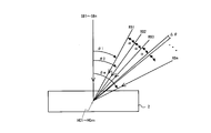
図1に示すように、たとえば、記録媒体2の表面へ垂直入射する信号光SB1~SBmに対して参照光RB1~RBmの交差角度θ1~θm(入射角度)を変化させながら、記録媒体2の同一単位記録領域に複数のホログラムを記録する角度多重記録を行う時、交差角度θ1で記録に要する時間だけ静止し、その後、交差角度θ2まで変化させて静止し、交差角度θ3まで移動して静止し、順次、ホログラムHG1~HGmを書き込むという動作を繰り返す手段、すなわち、光偏向装置が必要である。各ページには参照光の入射角に対応した該ページを特定するための情報(ページアドレス情報)が含まれる。交差角度の間隔すなわち角度間隔αは一定としておくことが一般的である。
また、一般に、ホログラム角度多重記録における再生において、記録媒体の移動、参照光の入射角を微調整しながら再生光を受光するので、アドレス情報を得るまでに参照光サーチを繰り返さなければならないため迅速なランダムアクセスが困難であり、データの再生速度の高速化が望まれている。
例えば、従来のホログラム装置において、記録時に参照光の交差角を可変制御する際の角度間隔αに対し、参照光の交差角をサーチング角度付近で連続的に変化させる際に、角度範囲Δθを、角度間隔αよりも狭小な値、すなわちΔθ<αとなるように設定する方法がある(特許文献1、参照)。
特開2007-240581号公報
特許文献1の先行技術では、同一のキーページ(基準角度に対応するページ)を参照光の基準角度近傍で連続的に記録し、キーページの角度選択性をあえて劣化させることにより、固定された参照光入射角度でキーページの読み出しすることを提案している。
しかし、参照光を一定角度に固定してキーページのサーチを試みた場合、記録媒体の反り、面振れ、または記録装置への記録媒体の再装着、記録媒体の他の記録装置への装着などで生じる角度変位等があると、アドレス情報が記録されている変調パターンに適合した参照光入射角度からはずれてしまうため再生像のSN比が劣化する、場合によってはユーザページとのクロストークが発生しアドレス情報の読み出しが困難となっていた。
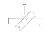
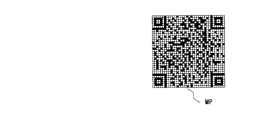
たとえば、図2に示すように、記録媒体が理想状態で一定であるとすると、記録媒体への所定角度での参照光RB照射によって再生された信号光ReSBにより、図3に示すように、所望の変調パターンMPが結像しアドレス情報が得られるが、特許文献1の先行技術によっても、同一のアドレス情報の2次元データ変調パターンを、所定の角度選択性が保証されている角度内で記録、もしくは連続的に記録した場合、その変調パターンを再生しようとすると、記録媒体の面振れ(図4の矢印)によって、角度多重の参照光移動方向に複数のホログラムが重なる現象が起こり、再生信号光ReSBが振れ、図5に示すように、例え同一の変調パターンの重なったパターンDMPとなり再生することは困難となる。
そこで、本発明の解決しようとする課題には、アクセス速度や、データの再生速度の高速化を可能にするホログラム装置及び記録再生方法を提供することが一例として挙げられる。
本発明の記録方法は、記録媒体を可動に保持する保持装置、並びに、可干渉性の参照光と記録すべき情報に応じて2次元データで変調された信号光の両光路を前記記録媒体内において交差させるように、前記参照光の交差角を所定の角度間隔で変化させる光偏向装置を含み、前記参照光及び前記信号光の光学干渉パターンをホログラムとして、前記角度間隔ごとにページ単位で前記記録媒体の単位記録領域に多重記録するホログラム装置における記録方法であって、
前記単位記録領域に記録すべき任意情報を含むユーザページを第1角度間隔で記録するステップと、
前記単位記録領域へのアクセスに必要なアドレス情報を含むアドレスページを記録するステップと、を含み、
前記アドレスページは、前記記録媒体の面振れによる再生像の移動範囲においては、その移動方向には値が変化しない一次元のデータのみを有することを特徴とする。
前記単位記録領域に記録すべき任意情報を含むユーザページを第1角度間隔で記録するステップと、
前記単位記録領域へのアクセスに必要なアドレス情報を含むアドレスページを記録するステップと、を含み、
前記アドレスページは、前記記録媒体の面振れによる再生像の移動範囲においては、その移動方向には値が変化しない一次元のデータのみを有することを特徴とする。
本発明の記録装置は、記録媒体を可動に保持する保持装置、並びに、可干渉性の参照光と記録すべき情報に応じて2次元データで変調された信号光の両光路を前記記録媒体内において交差させるように、前記参照光の交差角を所定の角度間隔で変化させる光偏向装置を含み、前記参照光及び前記信号光の光学干渉パターンをホログラムとして、前記角度間隔ごとにページ単位で前記記録媒体の単位記録領域に多重記録するホログラムの記録装置であって、
前記単位記録領域に記録すべき任意情報を含むユーザページを第1角度間隔で記録するとともに、前記単位記録領域へのアクセスに必要なアドレス情報を含むアドレスページを記録し、前記アドレスページは、前記記録媒体の面振れによる再生像の移動範囲においては、その移動方向には値が変化しない一次元のデータのみを有する変調パターンを有することを特徴とする。
前記単位記録領域に記録すべき任意情報を含むユーザページを第1角度間隔で記録するとともに、前記単位記録領域へのアクセスに必要なアドレス情報を含むアドレスページを記録し、前記アドレスページは、前記記録媒体の面振れによる再生像の移動範囲においては、その移動方向には値が変化しない一次元のデータのみを有する変調パターンを有することを特徴とする。
本発明によれば、アドレス情報を角度多重の参照光入射角度偏向において再生像が移動する方向に延在したバーコード状などの1次元データの変調パターンとすることでページ読み取り時の信号クロストークが生じてもアドレス情報の読み出しがある程度の品位で可能となる。
2 記録媒体
22 スピンドルモータ
23 ピックアップ
24 ピックアップ駆動部
25 光源駆動回路
26 空間光変調器駆動回路
27 再生光信号検出回路
31 ピックアップ位置検出回路
32 スライダサーボ回路
33 媒体回転角検知センサ
34 回転位置検出回路
35 スピンドルサーボ回路
37 制御回路
MD 参照光偏向駆動回路
4f 4f光学系
GM ガルバノミラー
CL コリメータレンズ
IS イメージセンサ
LD レーザ光源
OBA 第1対物レンズ
OBB 第2対物レンズ
PBS 偏光ビームスプリッタ
RB 参照光
SB 信号光
SLM 空間光変調器
22 スピンドルモータ
23 ピックアップ
24 ピックアップ駆動部
25 光源駆動回路
26 空間光変調器駆動回路
27 再生光信号検出回路
31 ピックアップ位置検出回路
32 スライダサーボ回路
33 媒体回転角検知センサ
34 回転位置検出回路
35 スピンドルサーボ回路
37 制御回路
MD 参照光偏向駆動回路
4f 4f光学系
GM ガルバノミラー
CL コリメータレンズ
IS イメージセンサ
LD レーザ光源
OBA 第1対物レンズ
OBB 第2対物レンズ
PBS 偏光ビームスプリッタ
RB 参照光
SB 信号光
SLM 空間光変調器
以下に本発明の実施形態としてホログラム装置の一例を図面を参照しつつ説明する。
<ホログラム装置>
実施形態としてディスク形状の記録媒体の情報を記録及び再生するホログラム装置を説明する。ただし、本実施形態はこのホログラム装置構成に縛られることなく、どのホログラム記録形態においても使用することが可能である。
実施形態としてディスク形状の記録媒体の情報を記録及び再生するホログラム装置を説明する。ただし、本実施形態はこのホログラム装置構成に縛られることなく、どのホログラム記録形態においても使用することが可能である。
図6はホログラム装置の一例のブロック図である。
ホログラム装置は、参照光偏向駆動回路MDと、記録媒体2のディスクを着脱自在に支持するターンテーブルで回転させるスピンドルモータ22と、記録媒体2から光ビームによって信号を読み出すピックアップ23と、該ピックアップを保持し記録媒体の半径方向Rに移動させるピックアップ駆動部24と、光源駆動回路25と、空間光変調器駆動回路26と、再生光信号検出回路27と、ピックアップ駆動部24に接続されピックアップの位置信号を検出するピックアップ位置検出回路31と、ピックアップ駆動部24に接続されこれに所定信号を供給するスライダサーボ回路32と、公知の光ピックアップ構成を有する記録媒体の回転角を検出する媒体回転角検知センサ33と、該媒体回転角検知センサに接続され記録媒体2の回転位置信号を生成する回転位置検出回路34と、スピンドルモータ22に接続されこれに所定信号を供給するスピンドルサーボ回路35とを備えている。
ホログラム装置は制御回路37を有しており、制御回路37は参照光偏向駆動回路MD、光源駆動回路25、空間光変調器駆動回路26、再生光信号検出回路27、ピックアップ位置検出回路31、スライダサーボ回路32、媒体回転角検知センサ33、回転位置検出回路34、並びにスピンドルサーボ回路35に接続されている。制御回路37はこれら回路からの信号に基づいて、これら駆動回路を介してピックアップに関する半径及び接線方向の位置の制御などを行う。制御回路37は、各種メモリ38を搭載したマイクロコンピュータからなり装置全体の制御をなすものであり、操作部39からの使用者による操作入力及び現在の装置の動作状況に応じて各種の制御信号を生成するとともに、使用者に動作状況などを表示する表示部40に接続されている。また、制御回路37はホログラムの記録再生シーケンスを制御する。
記録時、制御回路37は外部から入力されたホログラム記録すべきデータの符号化などの処理を実行し、所定信号を空間光変調器駆動回路26に供給する。ホログラム記録再生用レーザ光源LDに接続された光源駆動回路25は、射出する両光束の強度をホログラム記録時には強く再生時には弱くするように、レーザ光源LDの出力調整を行う。
制御回路37は、記録すべきホログラムを所定間隔(多重間隔)で記録できるようにホログラム単位記録領域を所定間隔で形成するように制御するとともに、単位記録領域において所定角度間隔で記録できるように、各種要素を制御する。
再生時、制御回路37は、ピックアップ23に搭載されたイメージセンサに接続された再生光信号検出回路27からの信号に基づいて復調及び誤り訂正処理をなすことにより、記録媒体に記録されていた2次元データを復元するように、各種要素を制御する。更に、制御回路37は、復元したデータに対して復号処理を施し、再生データを出力する。
制御回路37は、操作部又はピックアップ位置検出回路31からの位置信号に基づいてスライダ駆動信号を生成し、これをスライダサーボ回路32に供給する。スライダサーボ回路32はピックアップ駆動部24を介して、そのスライダ駆動信号による駆動電流に応じピックアップ23をディスク半径方向に移送せしめる。
記録再生時共通して、媒体回転角検知センサ33は、記録媒体2の内周側に付された検知用マークDM(図7参照)を検出し、その出力を回転位置検出回路34に供給する。回転位置検出回路34は回転位置信号を生成し、それを制御回路37に供給する。制御回路37は回転位置信号からトラック方向における単位記録領域の位置を判別する。制御回路37はスピンドル駆動信号を生成し、それをスピンドルサーボ回路35に供給し、スピンドルモータ22を制御して、記録媒体2を回転駆動する。
参照光偏向駆動回路MDは、ピックアップ23に搭載された後述する光偏向装置を制御して、参照光を、記録すべき情報に応じて2次元データで変調された信号光に対して、記録媒体内において交差させるように、参照光の交差角を所定の角度間隔で変化させる。
これらにより、記録時の運動している記録媒体に対する光スポットの相対位置を一定としてホログラムの形成時間を確保でき、再生時の参照光の位置や、角度を確定できる。
回転角検知用のマークDMを付された記録媒体2は、例えば、フォトポリマや、光異方性材料や、フォトリフラクティブ材料や、ホールバーニング材料、フォトクロミック材料など光学干渉パターンを保存できる透光性の光感応材料が用いられ、両面を保護層で覆う構造がとられている。回転角検知用のマークDMは保護層表面又は界面に例えば印刷またはCD等の光ディスク同様にピットなどの転写により形成されている。
<光ピックアップ>
図8はピックアップ23の概略構成を示す。ただし本実施形態はこれらのピックアップ構成に縛られることなくどのホログラム記録形態においても使用することが可能である。ピックアップ23は、記録光学系、再生光学系を含み、これらは筐体内に配置されている。
図8はピックアップ23の概略構成を示す。ただし本実施形態はこれらのピックアップ構成に縛られることなくどのホログラム記録形態においても使用することが可能である。ピックアップ23は、記録光学系、再生光学系を含み、これらは筐体内に配置されている。
ピックアップは、光源駆動回路25に接続されたレーザ光源LD、コリメータレンズCL、ハーフミラープリズムHP、偏光ビームスプリッタPBS、空間光変調器駆動回路26に接続された反射型の空間光変調器SLM、第1対物レンズOBA、信号光アパーチャーSAP、第2対物レンズOBB、再生光信号検出回路27に接続されたイメージセンサIS、参照光アパーチャーRAP、参照光偏向駆動回路MDに接続された光偏向装置10(ガルバノミラーGM、1対の同軸の照射レンズからなる4f光学系4f)から構成されている。
記録光学系の信号光学系は、レーザ光源LD、コリメータレンズCL、ハーフミラープリズムHP、偏光ビームスプリッタPBS、反射型の空間光変調器SLM、及び第1対物レンズOBAを含む。
記録光学系の参照光学系は、レーザ光源LD、コリメータレンズCL、ハーフミラープリズムHP、参照光アパーチャーRAP、及び光偏向装置10を含む。
再生光学系は、記録光学系と共通の参照光学系(レーザ光源LD、コリメータレンズCL、ハーフミラープリズムHP、参照光アパーチャーRAP、及び光偏向装置10)と第2対物レンズOBB、イメージセンサIS、信号光アパーチャーSAPを含む。
レーザ光源LDの波長は、記録媒体2の光学干渉パターンを保存できる透光性の光感応材料が反応する波長である。コリメータレンズCLはレーザ光源LDからの発散する可干渉光を平行光に変換するコリメート機能を有する。ハーフミラープリズムHPは平行光からに方向に分離して、参照光及び信号光用の光束を生成する。
一対の第1対物レンズOBA及び第2対物レンズOBBは互いの焦点が一致するように直線上に配置されている。一対の対物レンズOBA、OBBの共通焦点を外して、その近傍の第1対物レンズOBA側に記録媒体2が配置される。当該共通焦点にピンホールをおいて、信号光アパーチャーSAPが絞りの機能をなす。
反射型空間光変調器SLMは、マトリクス状に分割された複数の画素電極を有する反射型の液晶パネルなどで電気的に入射光を画素ごとに透過又は反射状態とする機能を有する。この空間光変調器SLMは空間光変調器駆動回路26からの記録すべきページデータ(平面上の明暗ドットパターンなどの2次元データの情報パターン)に基づいた分布を有するように光ビームを変調して、信号光を生成する。また空間光変調器駆動回路26からの信号に応じて再生時の信号光をすべて反射させないシャッタ機能も有する。なお、反射型の空間光変調器の例として複数の画素ミラーのマトリクスを有するDMD(Digital Micromirror Device)(登録商標)を用いることもでき、DMDは画素ミラー毎に入射光の一部を平行に偏向する空間変調機能を有し、電気的制御により必要な空間変調された信号光のみ第1対物レンズOBAへ供給することができる。また、透過型液晶パネルの空間光変調器を用いる場合は、偏光ビームスプリッタPBSの位置に鏡を配置して当該鏡と第1対物レンズOBの間に透過型空間光変調器を配置することもできる。
イメージセンサISは電荷結合装置(CCD)や相補型金属酸化膜半導体装置(CMOS)などのアレイからなる。
<光偏向装置>
参照光用光学系として、図8に示すように、参照光アパーチャーRAPは軸上開口を備え、軸上開口は入力光束を開口制限して適度な径に変換し参照光RBを生成する。
参照光用光学系として、図8に示すように、参照光アパーチャーRAPは軸上開口を備え、軸上開口は入力光束を開口制限して適度な径に変換し参照光RBを生成する。
ガルバノミラーGMは、その回転軸を駆動するアクチュエータを制御する参照光偏向駆動回路MDによって、駆動される。参照光偏向駆動回路MDにより例えばスッッテピングモータ駆動のガルバノミラーGMを一定角度間隔で回動される。本実施例では、参照光偏向駆動回路MDによりガルバノミラーGMで参照光入射角を微小角度間隔だけ変化させる微調整を行うことができる。
4f光学系4fは共焦点のレンズ構成であり両端の焦点面が互いに物体と像の結像関係にあるテレセントリック光学系であり、一方端のレンズ焦点(共役点)にガルバノミラーGMの回転軸が配置され他方端のレンズ焦点(共役点)に記録媒体2が配置される。よって、4f光学系では、ガルバノミラーGMから、どの方向に反射した光も、記録媒体上の特定の点(光軸上の共役点)へと導かれる。このように、光偏向装置は、ホログラムの角度多重記録を行う際に、参照光の照射角度を、ホログラムの記録位置を中心として変更するための、記録媒体へ照射する参照光を偏向する機構である。図は一例として焦点距離の等しい場合の4f光学系を示したが、これには限定されず、記録媒体へ照射する参照光の角度を変更する機構であれば他の光偏向装置も用い得る。
<ホログラム装置動作>
図8によりホログラム装置の概略動作を説明する。
図8によりホログラム装置の概略動作を説明する。
記録工程において、図8Aに示すように、レーザ光源LDから放射された可干渉性光束はコリメータレンズCLで平行光となりハーフミラープリズムHPで参照光及び信号光用に分離される。
信号光用光束はハーフミラープリズムHP反射後、偏光ビームスプリッタPBSを経て、空間光変調器駆動回路26からの信号により変調パターンを表示している空間光変調器SLMに入射する。空間光変調器SLMで、入射光が空間的に変調され信号光SBが生成されて反射され、偏光ビームスプリッタPBSに戻り、信号光SBが第1対物レンズOBAへ反射される。信号光SBは第1対物レンズOBAにより集光され記録媒体2に入射する。
参照光用光束はハーフミラープリズムHP通過後、参照光アパーチャーRAPで開口制限され参照光RBとなり、ガルバノミラーGMに入射する。ガルバノミラーGMで偏向された参照光RBは、4f光学系4fを経て、第1対物レンズOBAにより集光された信号光SBと記録媒体2内のある一点(単位記録領域)で交差する。この操作により記録媒体2内に光学干渉パターンを生じホログラムが記録される。
再生工程において、図8Bに示すように、空間光変調器SLMを全て透過状態とし信号光が第1対物レンズOBAへ反射されずに、記録媒体2に入射しないようにする。参照光RBは記録時同様にガルバノミラーGM及び4f光学系4fに入射し、参照光RBのみ偏向角度を選択し記録媒体2に入射させる。参照光RB照射で選択された交差角度に対応したホログラムのみが再生される。再生されたホログラムからの再生信号光ReSBは、第2対物レンズOBBによりイメージセンサIS上に結像する。この再生像を再生光信号検出回路27で読み取り、記録した信号が再生される。
ホログラム装置は、記録及び再生工程それぞれにおいて、記録すべき単位記録領域の複数を所定間隔(トラック方向Tにてシフト多重間隔)で逐次記録及び再生できるように、記録媒体を回転制御するとともに、単位記録領域の各々においてページ単位で所定角度間隔で角度多重記録できるように、制御される。
<シフト移動>
実施形態のホログラム装置において単位記録領域ごとの角度多重記録の前後に、シフト移動動作が行われるので、これを先に簡単に説明する。
実施形態のホログラム装置において単位記録領域ごとの角度多重記録の前後に、シフト移動動作が行われるので、これを先に簡単に説明する。
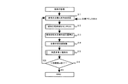
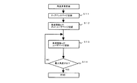
例えば、シフト移動ステップは図9に示すフローチャートに従って行われる。
まず、図8及び図9に示すように記録媒体2をホログラム装置のスピンドルに挿入固定する。その後、制御回路37からのデータ記録(又は再生)指令による目標アドレス指示に応じて、参照光の目標入射角度を固定(光偏向装置停止)し(ステップS1)、そして、媒体回転角検知センサ33を起動して(ステップS2)、目標のアドレス情報の記録媒体2における目標角度位置まで記録媒体2を回転し、そこで停止する(ステップS3)。つぎに、ピックアップ位置検出回路31及びスライダサーボ回路32を起動して、目標のアドレス情報の記録媒体2における目標半径位置までピックアップ23を半径方向Rにて移動し(ステップS4)、そこで停止する(シフト移動)。なお、ここで、目標のアドレス情報がページに既に記録されている場合は、シフト移動の後に、参照光のみ強度を低下させて照射し現在のページからアドレス情報が読み取れればアドレス情報の照合を行い、読み取れない場合は記録媒体の回転及び又はピックアップの移動のそれぞれについて微調整を行って再度参照光の照射による再度読み取りと再度アドレス情報照合を行う工程を繰り返しアドレス情報照合を完了するシフト移動の検査を行うこともできる(検査工程)。
シフト移動の後に、目標位置における単位記録領域にて角度多重の記録又は再生の工程を実行する(ステップS5)。そして、角度多重の記録又は再生の工程の継続又は終了を判別して(ステップS6)、継続であればステップS2へ戻り、他の目標アドレス指示を行い、記録終了であれば終了する。
これらシフト移動と角度多重のステップを順次行い、記録すべき単位記録領域を所定間隔で重なるように繰り返し、トラック方向Tに複数の単位記録領域(シフト多重記録)を形成する。
例えば、図7に示すように、記録媒体2のトラック(破線)上に所定間隔で複数の単位記録領域いわゆるブック(○で示す部分)が整列される。また、複数のブックを近接するもの同士例えばBS1を一群(シェルフ)としてまとめ、さらにBS2、BS3、BS4とシェルフごとに区分けして、アドレス情報として、例えば、シェルフBS1~BS4の各々の記録媒体における特定回転角度及び半径位置のブックの中の代表アドレスページに記録できる(シェルフアドレス情報)。この特定のアドレスページもブック内の特定角度位置に記録する。また、アドレスページには、ブック(単位記録領域)の各々の記録媒体における特定回転角度及び半径位置が記録できる(ブックアドレス情報)。アドレスページには、もちろん、単位記録領域内の参照光RBの入射角に対応したページを特定する情報が記録できる(ページアドレス情報)。このように、アドレス情報には、記録媒体ディスク上の回転角度位置及び半径位置(トラック位置)の位置情報や、単位記録領域内の参照光RBの入射角に対応したページを特定するページアドレス情報が含まれる。
アドレスページの他に、記録媒体において、単位記録領域に記録すべき画像やテキストなどの任意情報をブック内の所定角度位置にユーザページとして記録される。ユーザページにも少なくともページアドレス情報が含まれる。また、記録媒体には、どのシェルフどのブックどのページにどんなデータが記録されている等のインデックス情報(インデックスページ)も記録される。
このように、アドレスページには単位記録領域へのアクセスに必要なアドレス情報を含む変調パターンが含まれる。なお、アドレスページにも画像やテキストなどの任意情報をユーザエリアとして変調パターンに含ませることもできる。
<変調パターン>
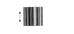
図23は、実施形態の方法における角度多重記録ホログラムで記録するアドレス情報を含むページの変調パターンを示す正面図である。
図23は、実施形態の方法における角度多重記録ホログラムで記録するアドレス情報を含むページの変調パターンを示す正面図である。
本実施形態においては、アドレス情報の変調パターンは、角度多重の参照光入射角度偏向において再生像が移動する方向(矢印)に延在したバーコード状(一次元コード)の変調パターン(再生像移動方向にはデータがなく、移動方向垂直方向には少なくとも1つのデータがあるパターン)とする。このように、クロストーク方向(再生像移動方向)の解像度を下げ一次元とすることで、面振れにも強いアドレス情報の変調パターンの再生が可能となる。すなわち、記録媒体2の単位記録領域に記録すべき任意情報を含むユーザページを所定間隔で記録するとともに、単位記録領域へのアクセスに必要なアドレス情報を含むアドレスページを記録し、アドレスページは、記録媒体の面振れによる再生像の移動範囲においては、その移動方向には値が変化しない一次元のデータのみを有する変調パターンを有することとする。
その他の実施形態としては、アドレスページは、図24に示すように、バーコードの同一パターンが断続的に続く表示パターンでもよい。また、アドレスページは、図25に示すように、別個のバーコードパターンが複数存在する表示パターンでも隣接アドレス情報パターンとクロストークが生じても読み取りが可能な範囲であれば、本発明の効果は維持できる。すなわち、再生像移動方向の解像度を下げデータを保持できれば、表示パターンは角度多重の参照光角度偏向において再生像が移動する方向に延在したバーコード状の変調パターンであるが、必ずしも単純な1次元バーコードである必要はない。
図24、図25に示すような、複数の2次元バーコードを組み合わせたアドレス情報表示パターンとすることでアドレス情報のビット数を増やすことができる。
<角度多重工程:記録>
まず、ホログラム装置の角度多重工程(ステップS5)における角度多重記録を、一例として、記録媒体の空白な単位記録領域に1つのアドレスページを先頭に続けて十分に単位記録領域の容量を超える量の一連のユーザページを記録する場合について図10に示すフローチャートで説明する。
まず、ホログラム装置の角度多重工程(ステップS5)における角度多重記録を、一例として、記録媒体の空白な単位記録領域に1つのアドレスページを先頭に続けて十分に単位記録領域の容量を超える量の一連のユーザページを記録する場合について図10に示すフローチャートで説明する。
当初のシフト移動で、参照光偏向駆動回路MDがガルバノミラーGMの偏向角を制御して、参照光RBの入射角を指定角度θn(例えば、ブックの先頭ページの初期値)に設定してあり、参照光RBおよび記録光SBは、指定記録領域Cに対して照射されない。
目標位置における単位記録領域にピックアップの光照射位置が確定した後、空間光変調器駆動回路が空間光変調器SLMを制御しこれにアドレスページの変調パターンが表示されかつ、光源がオンとされ、図11に示すように、指定記録領域Cに参照光RBおよび記録光SB両光路を記録媒体2内において交差させ(ステップS11)、相対的に静止した状態とする。これにより、指定記録領域Cには、指定角度θnに対応するアドレスページのホログラムが形成され、このアドレス情報が記録される。なお、ここで、データ記録の後に、信号光を遮断して参照光のみの強度を低下させて照射し現在のアドレスページからデータを再生し、再生データにエラーがあるかどうかの検査を行うこともできる(検査工程)。
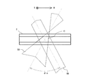
次に、参照光偏向駆動回路MDは、図12に示すように、ガルバノミラーGMの偏向角を変更させ参照光RBの入射角を所定角度θn+1に設定し、すなわち、アドレスページの角度位置から参照光RBを所定のアドレスページ角度間隔tsだけ回動する(ステップS12)と共に、空間光変調器の表示をユーザページの変調パターンに切り替える制御を行い、相対的に静止した状態とする。これにより、指定記録領域Cには、指定角度θn+1に対応するユーザページのホログラムが形成される。
次に、参照光偏向駆動回路MDは、図13に示すように、ガルバノミラーGMの偏向角を変更させ、初回のユーザページの角度位置から参照光RBを次のユーザページ角度間隔tdだけ回動する(ステップS13)と共に、空間光変調器の表示を次のユーザページの変調パターンに切り替える制御を行い、相対的に静止した状態とする。これにより、指定記録領域Cには、次のユーザページのホログラムが形成される。
その後に、ユーザページの記録処理を参照光RBの角度間隔ts合計が最大角度θM(容量)までステップS13を繰り返すことにより、複数のユーザページが順次1ブック内に多重記録される。すなわち、参照光RBの入射角が最大角度か否かを判別して(ステップS14)、最大角度θMでなければステップS13へ戻り、最大角度であれば終了する。
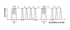
この実施形態では、角度間隔ごとにページ単位で記録媒体の単位記録領域に多重記録するホログラム装置における記録方法において、単位記録領域に記録すべき任意情報を含むユーザページの複数をユーザページ角度間隔td(第1角度間隔)で記録する一方で、単位記録領域へのアクセスに必要なアドレス情報を含むアドレスページ(θn)は、隣接するユーザページ(θn+1)からユーザページ角度間隔tdより大なるアドレスページ角度間隔ts(第2角度間隔)で離間させて、記録する。ここで、注意することは、図13に示すように、かかるアドレスページ角度間隔tsが記録媒体の表面の面振れ角度幅Wv以上に設定されることが好ましい。読み取り時のアドレスページとユーザページの重なりによる記録媒体の面振れの影響を回避するためである。これにより、再生像のSN比劣化防止、両者のクロストーク防止が可能となり、アドレス情報の読み出しが確実となる。ここで記録媒体の表面の面振れ角度幅とはイメージセンサ受光面において結像された再生像の面振れ前後の移動距離を光偏向装置による参照光の入射角度の精度に換算した幅である。
また、ユーザページ角度間隔tdは一定の角度である必要はない(アドレスページと隣接するデータページが離れていればよい)。
さらに、アドレスページが記録媒体の表面の面振れ角度幅Wv以下の所定角度θnを中心にアドレスページ許容角度範囲VR内にて記録されることが好ましい。読み取り時のアドレスページ自体の記録媒体の面振れの影響を回避するためである。
また、この実施形態ではアドレスページは、ユーザページの群の先頭に記録されているが、他の変形例では、ユーザページを先頭に記録して、次にアドレスページを記録して、アドレスページがユーザページの群に挟まれて記録されるようにすることもできる。また、ユーザページの群の最終ページ後にもアドレスページは記録できる。
さらなる他の変形例としては、例えば、図7に示すように、単位記録領域の一群(シェルフ)において、代表アドレスページにそれぞれの単位記録領域へのアクセスに必要なアドレス情報を記録して、代表アドレスページを記録する参照光の交差角を、ユーザページを記録する参照光の交差角とは異ならしめ、代表アドレスページ同士を記録する参照光の交差角は同一とすることもできる。これにより、単位記録領域の一群(シェルフ)ごとのサーチを高速化できる。
また、この実施形態ではアドレスページは単位記録領域(ブック)の1つにおいて1つだけ記録されているが、これに限定されず、アドレスページは、単位記録領域(ブック)の1つにおいて複数記録することもできる。例えば、図14に示すように、参照光RBのアドレスページ入射指定角度θnに加えて別個のアドレスページ入射指定角度θxの位置に2番目のアドレスページを同一のブック内に記録できる。これにより、ブック内のページアドレス情報をさらに細かく分割できるためブック内の目的ページのサーチが可能となる。
さらに、アドレスページを、単位記録領域ごとに参照光の交差角が異なるように記録することもできる。これにより、単位記録領域ごとのサーチが高速化できる。例えば、図15に示すように、同一の記録媒体2内において、1つの単位記録領域Cに参照光RBのアドレスページ入射指定角度θnに加えて別個の単位記録領域Cyにアドレスページ入射指定角度θyの位置にアドレスページを記録できる。もちろん、別個の単位記録領域Cyにアドレスページ入射指定角度θnで記録も可能である。
さらなる他の変形例としては、例えば、図16に示すように、アドレスページの3つを隣接したアドレスページの一群として、記録できる。この場合、アドレスページ群内の複数のアドレスページのアドレス情報が同一のデータであり、アドレスページ許容角度範囲VR内にて、隣接アドレスページの間隔がユーザページ角度間隔tdより小なる第3角度間隔taで記録される。アドレスページ許容角度範囲VRは記録媒体の表面の面振れ角度幅Wv以下なので、第3角度間隔taも面振れ角度幅Wv以下であり、アドレスページの所定角度θnを中心に配置されるようにすることが好ましい。
すなわち、図6に示す参照光偏向駆動回路MDは、図8に示すガルバノミラーGMの偏向角を変化させて、参照光RBの入射角について指定角度θnを含む2・taの角度範囲で間欠的に変化させる。参照光RBの入射角が第3角度範囲taごと変化させ静止している間、参照光RBおよび記録光SBは、指定記録領域Cに対して照射し続けられる。このとき、記録光SBは、空間光変調器SLMによって同一アドレス情報を含むような変調パターンの光に変調されている。これによれば、同一のアドレスページ複数がユーザページの間隔より近接して記録された状態となる。このアドレスページ群を再生する際には、ある程度参照光の入射角θnから偏倚があっても再生信号光が得られる。よって、例えば、入射角θnのアドレスページをサーチする時にこれを高速に読み出すことができる。
<角度多重工程:再生>
次に、ホログラム装置の角度多重工程(ステップS5)における角度多重再生を、一例として、記録媒体の単位記録領域に1つのアドレスページを先頭に続けてユーザページを記録したものの特定のユーザページ再生の場合について図17に示すフローチャートで説明する。
次に、ホログラム装置の角度多重工程(ステップS5)における角度多重再生を、一例として、記録媒体の単位記録領域に1つのアドレスページを先頭に続けてユーザページを記録したものの特定のユーザページ再生の場合について図17に示すフローチャートで説明する。
制御回路37からのデータ再生指令による目標アドレス指示(例えば、ブックアドレス及びページアドレス)に応じて、図9に説明したような当初のシフト移動で、目標ブック(単位記録領域)のアドレスページに到達した時点で、目標のアドレス情報により参照光偏向駆動回路MDがガルバノミラーGMの偏向角を制御することにより、参照光RBの入射角を一定角度(ts、td)で変化させる(ステップS21)。ここで、読み出したページアドレス情報に基づき、制御回路37は現時点でアクセスしているアドレスページから読み出し開始ユーザページまでの入射角を計算し、参照光偏向駆動回路MDによりガルバノミラーGMの偏向角を所定間隔だけ変化するように制御する。これにより、ブックにおいては、参照光RBの入射角が記録時の指定角度に対してある程度の範囲で合えば、アドレスページに対応した十分な輝度の再生信号光ReSBが生じる。これにより、イメージセンサISは、ページに対応した再生信号光ReSBをイメージセンサISで受光し、これからの受光信号に基づいて再生光信号検出回路27を介し、制御回路37へデータを送信する(ステップS22)。ここで、制御回路37は、目標のアドレス情報と取得したページアドレス(既に記録されている)とのアドレス情報照合を行い(ステップS23)、読み取れない場合は参照光偏向駆動回路MDによりガルバノミラーGMで参照光入射角を微小角度間隔だけ変化させる微調整を行って(ステップS24)、再度参照光の照射による再度読み取りと再度アドレス情報照合を行う工程を繰り返し、アドレス情報照合を完了すれば、ユーザページの読み出し開始する(ステップS25)。
その後、制御回路37は、取得したページアドレス情報に基づき、現時点でアクセスしているユーザページが再生すべき最後のユーザページか否かを判断し、最後のユーザページの場合、制御回路37は、一連の再生処理を終了する。
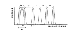
図18に上記再生ステップで得られた再生信号の強度と再生用参照光入射角度との関係を示す。図に示すように、アドレスページ(θn)とその隣接ユーザページ(θn+1)のアドレスページ角度間隔tsは、ユーザページを記録する所定のユーザページ角度間隔tdよりも広く設定されて(ts>td)、さらに、アドレスページ角度間隔tsを面振れ値Wvよりも大きくしてあるので、再生光信号検出回路27は、イメージセンサISからの受光信号に基づいてユーザページへの記録されたアドレスデータをアドレスページから確実に再生することができる。
図19に、図16に示す変形例(アドレスページを1つでなく隣接した3つのアドレスページの一群として記録した場合)の上記再生ステップで得られた再生信号の強度と再生用参照光入射角度との関係を示す。これによれば、アドレスページについては面振れ角度幅Wvより小の第3角度間隔taで3つの同じアドレスページを群とし記録しているので、図示のように、ユーザページの再生信号強度よりも大なるアドレスページの再生信号強度を得ることができることが分かる。これにより、本実施例の効果として1次元のアドレスデータであればクロストークしても読み取ることが可能となり、また面振れ範囲においてほぼ同一の信号強度でアドレスデータが再生できるようになる。
図20は、図16に示す変形例と図14に示す変形例とを組み合わせて、参照光RBのアドレスページ入射指定角度θnに加えて別個のアドレスページ入射指定角度θxの位置に2番目のアドレスページを同一の1つのブック内に記録した場合の上記再生ステップで得られた再生信号の強度と再生用参照光入射角度との関係を示す。これにより、ブック内のページアドレス情報をさらに細かく分割できるためブック内の目的ページのサーチが可能となることが分かる。
図21は、図16に示す変形例と図15に示す変形例とを組み合わせて、同一の記録媒体内において、ブックAの単位記録領域Cに参照光RBのアドレスページ入射指定角度θnを、別個のブックBの単位記録領域Cyにアドレスページ入射指定角度θyの位置にアドレスページを記録した場合の上記再生ステップで得られた再生信号の強度と再生用参照光入射角度との関係を示す。これにより、ブックごとに異なる参照光入射角度位置にアドレスページを記録するので、例えば、複数のブックを固まり(ブックシェルフ)としたデータ単位の先頭のブックAのみ異なる参照光入射角度でブックアドレス情報が記録され、ブックBの参照光入射角度ではアドレス再生信号が再生されないため、ブックAのみ内の目的ページの高速サーチが可能となることが分かる。
<サーチ方法>
サーチ方法として一例を示す。例えば、図7に示すトラック上にシェルフBS1~BS4が記録された記録媒体2において全ブック(少なくとも同一トラック)のアドレスページへの参照光入射角度(記録時)を同一に設定しておけば、同一トラック上のシェルフBS1及びBS3において、両シェルフのブックアドレス情報をサーチする場合、記録媒体を回転移動させることで目的のブックアドレス情報を高速に取得できる。例えば、図22はかかる場合(シェルフBS1の先頭ブックAのアドレスページA及びBS3の先頭ブックBのアドレスページBの参照光入射角度が同一で、他のページの参照光入射角度とは異なる場合)の上記図9及び図17で説明した再生ステップで得られた再生信号強度と記録媒体回転角度移動量との関係を示す。なお、図22中、ssはシェルフBS1の先頭ブックAとBS3の先頭ブックBのとの間の距離を、bsは隣接ブックのシフト多重距離を示す。アドレス情報が記録されているアドレスページ参照光入射角度とユーザページ参照光入射角度が異なるので、サーチ中、アドレスページ記録用角度で行ってもユーザページの再生信号強度がでないので、再生信号のSN比がよくなる。図22から、ブックA及びB信号が再生されないので、アドレス再生信号のSN比がよくなる。図22から、ブックA及びBのアドレスページ参照光入射角度ではユーザページのデータが再生されないため、ブックA及びBのみ内の目的ページの高速サーチが可能となることが分かる。
サーチ方法として一例を示す。例えば、図7に示すトラック上にシェルフBS1~BS4が記録された記録媒体2において全ブック(少なくとも同一トラック)のアドレスページへの参照光入射角度(記録時)を同一に設定しておけば、同一トラック上のシェルフBS1及びBS3において、両シェルフのブックアドレス情報をサーチする場合、記録媒体を回転移動させることで目的のブックアドレス情報を高速に取得できる。例えば、図22はかかる場合(シェルフBS1の先頭ブックAのアドレスページA及びBS3の先頭ブックBのアドレスページBの参照光入射角度が同一で、他のページの参照光入射角度とは異なる場合)の上記図9及び図17で説明した再生ステップで得られた再生信号強度と記録媒体回転角度移動量との関係を示す。なお、図22中、ssはシェルフBS1の先頭ブックAとBS3の先頭ブックBのとの間の距離を、bsは隣接ブックのシフト多重距離を示す。アドレス情報が記録されているアドレスページ参照光入射角度とユーザページ参照光入射角度が異なるので、サーチ中、アドレスページ記録用角度で行ってもユーザページの再生信号強度がでないので、再生信号のSN比がよくなる。図22から、ブックA及びB信号が再生されないので、アドレス再生信号のSN比がよくなる。図22から、ブックA及びBのアドレスページ参照光入射角度ではユーザページのデータが再生されないため、ブックA及びBのみ内の目的ページの高速サーチが可能となることが分かる。
Claims (17)
- 記録媒体を可動に保持する保持装置、並びに、可干渉性の参照光と記録すべき情報に応じて2次元データで変調された信号光の両光路を前記記録媒体内において交差させるように、前記参照光の交差角を所定の角度間隔で変化させる光偏向装置を含み、前記参照光及び前記信号光の光学干渉パターンをホログラムとして、前記角度間隔ごとにページ単位で前記記録媒体の単位記録領域に多重記録するホログラム装置における記録方法であって、
前記単位記録領域に記録すべき任意情報を含むユーザページを第1角度間隔で記録するステップと、
前記単位記録領域へのアクセスに必要なアドレス情報を含むアドレスページを記録するステップと、を含み、
前記アドレスページは、前記記録媒体の面振れによる再生像の移動範囲においては、その移動方向には値が変化しない一次元のデータのみを有する変調パターンを有することを特徴とする記録方法。 - 前記アドレスページを、隣接する前記ユーザページから前記第1角度間隔より大なる第2角度間隔で離間させて、前記第2角度間隔が前記記録媒体の表面の面振れ角度幅以上であることを特徴とする請求項1に記載の記録方法。
- 前記アドレスページが前記記録媒体の表面の面振れ角度幅以下の角度範囲内にて記録されることを特徴とする請求項1又は2に記載の記録方法。
- 前記アドレスページは、前記ユーザページの群に挟まれて記録されることを特徴とする請求項1~3のいずれか1に記載の記録方法。
- 前記アドレスページは、前記ユーザページの群の先頭に記録されることを特徴とする請求項1~3のいずれか1に記載の記録方法。
- 前記単位記録領域の複数において、それぞれの前記アドレスページは前記単位記録領域の複数からなる群の内のいずれかの単位記録領域へのアクセスに必要なアドレス情報を含む代表アドレスページであり、前記代表アドレスページを記録する前記参照光の交差角は前記ユーザページを記録する前記参照光の交差角とは異なること、前記代表アドレスページ同士を記録する前記参照光の交差角は同一であること、を特徴とする請求項1~5のいずれか1に記載の記録方法。
- 前記アドレスページは、前記単位記録領域の1つにおいて複数に記録されることを特徴とする請求項1~6のいずれか1に記載の記録方法。
- 前記アドレスページは、前記単位記録領域ごとに前記参照光の交差角が異なるように記録されることを特徴とする請求項1~7のいずれか1に記載の記録方法。
- 前記アドレスページは、前記角度範囲内にて、アドレス情報が同一のデータであるアドレスページの複数が第1角度間隔より小なる第3角度間隔で隣接したアドレスページ群として、記録されることを特徴とする請求項1~7のいずれか1に記載の記録方法。
- 記録媒体を可動に保持する保持装置、並びに、可干渉性の参照光と記録すべき情報に応じて2次元データで変調された信号光の両光路を前記記録媒体内において交差させるように、前記参照光の交差角を所定の角度間隔で変化させる光偏向装置を含み、前記参照光及び前記信号光の光学干渉パターンをホログラムとして、前記角度間隔ごとにページ単位で前記記録媒体の単位記録領域に多重記録するホログラムの記録装置であって、
前記単位記録領域に記録すべき任意情報を含むユーザページを第1角度間隔で記録するとともに、前記単位記録領域へのアクセスに必要なアドレス情報を含むアドレスページを記録し、前記アドレスページは、前記記録媒体の面振れによる再生像の移動範囲においては、その移動方向には値が変化しない一次元のデータのみを有する変調パターンを有することを特徴とする記録装置。 - 前記アドレスページを、隣接する前記ユーザページから前記第1角度間隔より大なる第2角度間隔で離間させて、前記第2角度間隔が前記記録媒体の表面の面振れ角度幅以上であることを特徴とする請求項10に記載の記録装置。
- 前記アドレスページは、前記ユーザページの群に挟まれて記録されることを特徴とする請求項10~11のいずれか1に記載の記録装置。
- 前記アドレスページは、前記ユーザページの群の先頭に記録されることを特徴とする請求項10~11のいずれか1に記載の記録装置。
- 前記単位記録領域の複数において、それぞれの前記アドレスページは前記単位記録領域の複数からなる群の内のいずれかの単位記録領域へのアクセスに必要なアドレス情報を含む代表アドレスページであり、前記代表アドレスページを記録する前記参照光の交差角は前記ユーザページを記録する前記参照光の交差角とは異なること、前記代表アドレスページ同士を記録する前記参照光の交差角は同一であること、を特徴とする請求項10~13のいずれか1に記載の記録装置。
- 前記アドレスページは、前記単位記録領域の1つにおいて複数に記録されることを特徴とする請求項10~14のいずれか1に記載の記録装置。
- 前記アドレスページは、前記単位記録領域ごとに前記参照光の交差角が異なるように記録されることを特徴とする請求項10~15のいずれか1に記載の記録装置。
- 前記アドレスページは、前記角度範囲内にて、アドレス情報が同一のデータであるアドレスページの複数が第1角度間隔より小なる第3角度間隔で隣接したアドレスページ群として、記録されることを特徴とする請求項10~16のいずれか1に記載の記録装置。
Priority Applications (1)
| Application Number | Priority Date | Filing Date | Title |
|---|---|---|---|
| PCT/JP2008/066242 WO2010029613A1 (ja) | 2008-09-09 | 2008-09-09 | ホログラム装置及び記録方法 |
Applications Claiming Priority (1)
| Application Number | Priority Date | Filing Date | Title |
|---|---|---|---|
| PCT/JP2008/066242 WO2010029613A1 (ja) | 2008-09-09 | 2008-09-09 | ホログラム装置及び記録方法 |
Publications (1)
| Publication Number | Publication Date |
|---|---|
| WO2010029613A1 true WO2010029613A1 (ja) | 2010-03-18 |
Family
ID=42004882
Family Applications (1)
| Application Number | Title | Priority Date | Filing Date |
|---|---|---|---|
| PCT/JP2008/066242 Ceased WO2010029613A1 (ja) | 2008-09-09 | 2008-09-09 | ホログラム装置及び記録方法 |
Country Status (1)
| Country | Link |
|---|---|
| WO (1) | WO2010029613A1 (ja) |
Cited By (1)
| Publication number | Priority date | Publication date | Assignee | Title |
|---|---|---|---|---|
| WO2015011745A1 (ja) * | 2013-07-22 | 2015-01-29 | 日立コンシューマエレクトロニクス株式会社 | 光情報記録媒体、光情報記録方法および光情報再生方法 |
Citations (3)
| Publication number | Priority date | Publication date | Assignee | Title |
|---|---|---|---|---|
| JP2006155831A (ja) * | 2004-11-30 | 2006-06-15 | Fujitsu Ltd | ホログラム記録媒体及びホログラム記録再生装置 |
| JP2007240581A (ja) * | 2006-03-06 | 2007-09-20 | Fujitsu Ltd | ホログラム記録装置 |
| JP2008097701A (ja) * | 2006-10-11 | 2008-04-24 | Sony Corp | 光ディスク装置及びディスクチルト補正方法、並びに光ディスク |
-
2008
- 2008-09-09 WO PCT/JP2008/066242 patent/WO2010029613A1/ja not_active Ceased
Patent Citations (3)
| Publication number | Priority date | Publication date | Assignee | Title |
|---|---|---|---|---|
| JP2006155831A (ja) * | 2004-11-30 | 2006-06-15 | Fujitsu Ltd | ホログラム記録媒体及びホログラム記録再生装置 |
| JP2007240581A (ja) * | 2006-03-06 | 2007-09-20 | Fujitsu Ltd | ホログラム記録装置 |
| JP2008097701A (ja) * | 2006-10-11 | 2008-04-24 | Sony Corp | 光ディスク装置及びディスクチルト補正方法、並びに光ディスク |
Cited By (1)
| Publication number | Priority date | Publication date | Assignee | Title |
|---|---|---|---|---|
| WO2015011745A1 (ja) * | 2013-07-22 | 2015-01-29 | 日立コンシューマエレクトロニクス株式会社 | 光情報記録媒体、光情報記録方法および光情報再生方法 |
Similar Documents
| Publication | Publication Date | Title |
|---|---|---|
| EP1833048B1 (en) | Hologram recorder and hologram recording method | |
| US7209270B2 (en) | Method and apparatus for phase correlation holographic drive | |
| JP5081741B2 (ja) | 光情報記録装置、光情報記録方法、光情報記録再生装置および光情報記録再生方法 | |
| JP4574183B2 (ja) | ホログラム記録媒体 | |
| JP2009087448A (ja) | ホログラム記録再生装置及びホログラム記録再生方法 | |
| JP2006085834A (ja) | 光情報記録装置及び光情報再生装置 | |
| JP4295636B2 (ja) | ホログラム記録方法 | |
| JP4521055B2 (ja) | 記録再生方法、記録媒体及び記録再生装置 | |
| JP5125351B2 (ja) | 光情報記録再生装置 | |
| US8472298B2 (en) | Optical information recording and reproducing apparatus and optical information recording method | |
| JP2009080890A (ja) | 光情報記録再生装置及び光学的に情報を記録再生する方法 | |
| JPH1152827A (ja) | 3次元ホログラフィックデータ格納システム | |
| US9336811B2 (en) | Information recording apparatus, information reproducing apparatus and recording media | |
| JP2005310308A (ja) | ホログラム記録再生装置及びホログラム記録再生方法 | |
| WO2010029608A1 (ja) | ホログラム装置及び記録方法 | |
| US20080101196A1 (en) | Apparatus and method for record and/or reproduce holographic information | |
| WO2010029613A1 (ja) | ホログラム装置及び記録方法 | |
| US20090268267A1 (en) | Hologram recording carrier and hologram apparatus | |
| JP4738935B2 (ja) | ホログラム記録方法およびホログラム記録装置 | |
| JP6894110B2 (ja) | ホログラム記録再生装置 | |
| JP2008299992A (ja) | ホログラフィックメモリ記録装置、ホログラフィック再生装置、又はホログラフィック記録再生装置 | |
| JP2012138148A (ja) | 情報記録再生装置および情報記録再生方法 | |
| JP6956521B2 (ja) | ホログラム記録装置およびホログラム記録方法 | |
| JP5802494B2 (ja) | ホログラフィックメモリ再生装置、ホログラフィックメモリ再生方法およびホログラム記録媒体 | |
| KR100786789B1 (ko) | 각도 다중화 방법을 사용하는 공선 방식의 홀로그래픽데이터 저장장치 |
Legal Events
| Date | Code | Title | Description |
|---|---|---|---|
| 121 | Ep: the epo has been informed by wipo that ep was designated in this application |
Ref document number: 08810297 Country of ref document: EP Kind code of ref document: A1 |
|
| NENP | Non-entry into the national phase |
Ref country code: DE |
|
| NENP | Non-entry into the national phase |
Ref country code: JP |
|
| 122 | Ep: pct application non-entry in european phase |
Ref document number: 08810297 Country of ref document: EP Kind code of ref document: A1 |