WO2010026963A1 - Work tool - Google Patents
Work tool Download PDFInfo
- Publication number
- WO2010026963A1 WO2010026963A1 PCT/JP2009/065259 JP2009065259W WO2010026963A1 WO 2010026963 A1 WO2010026963 A1 WO 2010026963A1 JP 2009065259 W JP2009065259 W JP 2009065259W WO 2010026963 A1 WO2010026963 A1 WO 2010026963A1
- Authority
- WO
- WIPO (PCT)
- Prior art keywords
- rear cover
- tool
- motor housing
- motor
- housing
- Prior art date
Links
Images


Classifications
-
- B—PERFORMING OPERATIONS; TRANSPORTING
- B25—HAND TOOLS; PORTABLE POWER-DRIVEN TOOLS; MANIPULATORS
- B25F—COMBINATION OR MULTI-PURPOSE TOOLS NOT OTHERWISE PROVIDED FOR; DETAILS OR COMPONENTS OF PORTABLE POWER-DRIVEN TOOLS NOT PARTICULARLY RELATED TO THE OPERATIONS PERFORMED AND NOT OTHERWISE PROVIDED FOR
- B25F5/00—Details or components of portable power-driven tools not particularly related to the operations performed and not otherwise provided for
- B25F5/02—Construction of casings, bodies or handles
-
- B—PERFORMING OPERATIONS; TRANSPORTING
- B24—GRINDING; POLISHING
- B24B—MACHINES, DEVICES, OR PROCESSES FOR GRINDING OR POLISHING; DRESSING OR CONDITIONING OF ABRADING SURFACES; FEEDING OF GRINDING, POLISHING, OR LAPPING AGENTS
- B24B23/00—Portable grinding machines, e.g. hand-guided; Accessories therefor
- B24B23/02—Portable grinding machines, e.g. hand-guided; Accessories therefor with rotating grinding tools; Accessories therefor
-
- B—PERFORMING OPERATIONS; TRANSPORTING
- B24—GRINDING; POLISHING
- B24B—MACHINES, DEVICES, OR PROCESSES FOR GRINDING OR POLISHING; DRESSING OR CONDITIONING OF ABRADING SURFACES; FEEDING OF GRINDING, POLISHING, OR LAPPING AGENTS
- B24B55/00—Safety devices for grinding or polishing machines; Accessories fitted to grinding or polishing machines for keeping tools or parts of the machine in good working condition
- B24B55/04—Protective covers for the grinding wheel
- B24B55/05—Protective covers for the grinding wheel specially designed for portable grinding machines
- B24B55/052—Protective covers for the grinding wheel specially designed for portable grinding machines with rotating tools
-
- B—PERFORMING OPERATIONS; TRANSPORTING
- B25—HAND TOOLS; PORTABLE POWER-DRIVEN TOOLS; MANIPULATORS
- B25F—COMBINATION OR MULTI-PURPOSE TOOLS NOT OTHERWISE PROVIDED FOR; DETAILS OR COMPONENTS OF PORTABLE POWER-DRIVEN TOOLS NOT PARTICULARLY RELATED TO THE OPERATIONS PERFORMED AND NOT OTHERWISE PROVIDED FOR
- B25F5/00—Details or components of portable power-driven tools not particularly related to the operations performed and not otherwise provided for
- B25F5/008—Cooling means
Abstract
Description
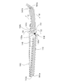
駆動スイッチは、操作部及びスイッチ部を少なくとも含む。操作部は、モータハウジングとリアカバーの双方の上に長尺状に延在し作業者の手による握り動作によって操作される操作部分として構成される。すなわち、グリップ部を兼ねるモータハウジングと、グリップ部を兼ねるリアカバーとにわたって長尺状の操作部が延在している。この操作部は、操作時において所定の回動支点を中心にして回転動作される回動式として構成されてもよいし、或いは操作部がスイッチ操作時に平行移動する平行移動式やスライド移動するスライド移動式として構成されてもよい。なお、操作部を回動式として構成する場合、操作部のための回動支点は、モータハウジングに設けられてもよいし、或いはリアカバーに設けられてもよい。スイッチ部は、リアカバー内に配設され操作部の操作によって作動して駆動モータの通電制御を行なうとともに開口部を通じて操作部と接続されるスイッチ部分として構成される。 The drive motor is configured as a motor having a function of driving a tool that performs a predetermined machining operation on a workpiece. The tool driven by the drive motor acts on the workpiece to perform a predetermined machining operation. As the “tool” here, typically, a grindstone or a tool for subjecting a workpiece to grinding work or polishing work can be used. However, a sanding disk, a wire brush, etc. are also included in the tool here. Is done. Moreover, this tool may be made into one component of a work tool as needed, or may be made into a component different from a work tool. The motor housing is configured as a housing (accommodating body) that accommodates the drive motor. The tool attachment portion is configured as a part to which a tool is attached on the housing front end side of the motor housing. The rear cover includes at least a cylindrical portion and an opening. A cylindrical part is comprised as a cover body attached to the housing rear end side on the opposite side to a tool attachment part among motor housings. For the purpose of reducing the number of parts and the purpose of ensuring the strength by a single structure, the cylindrical portion is preferably an integrally formed structure. The opening is configured as an opening formed in the cylindrical wall of the cylindrical portion. The rear cover constitutes a grip portion that is gripped by an operator by the rear cover and the motor housing.
The drive switch includes at least an operation unit and a switch unit. The operation portion is configured as an operation portion that extends in a long shape on both the motor housing and the rear cover and is operated by a gripping operation by a worker's hand. That is, the long operation part extends over the motor housing that also serves as the grip part and the rear cover that also serves as the grip part. The operation unit may be configured as a rotation type that rotates around a predetermined rotation fulcrum during operation, or a parallel movement type in which the operation unit moves in parallel when the switch is operated, or a slide that slides. It may be configured as mobile. In addition, when comprising an operation part as a rotation type, the rotation fulcrum for an operation part may be provided in a motor housing, or may be provided in a rear cover. The switch portion is configured as a switch portion that is disposed in the rear cover and is operated by operating the operation portion to control energization of the drive motor and is connected to the operation portion through the opening.
103 本体部(工具ハウジング)
105 モータハウジング
105a,105b 凹部
106 リアハウジング
107 ギアハウジング
111 動力伝達機構
113 小ベベルギア
115 大ベベルギア
117 スピンドル
119 砥石(先端工具)
121 駆動モータ(モータ)
123 出力軸
124 冷却ファン
125 電機子
126 軸受
127 固定子
128 軸受
129 整流子
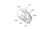
131 リアカバー
131a 筒状部
132 取付ネジ
133 開口部
135,137 延在壁
138 リブ
139 通風窓
141 スイッチ部
143 操作レバー
143a 前端部
143b 後端部
143c 凸部
145 補強部材
150 ロック部材
150a 回転軸
150b 係合部
150c 操作部
151 バネ部材
160 電源コード 101 Electric disc grinder (Electric tool)
103 Main body (tool housing)
105
121 Drive motor
123
Claims (3)
- 被加工材に対し所定の加工作業を行う工具を駆動するための駆動モータと、
前記駆動モータを収容するモータハウジングと、
前記モータハウジングのハウジング前端側において前記工具が取り付けられる工具取り付け部と、
前記工具取り付け部とは反対のモータハウジング後端領域に取り付けられる筒状部、および前記筒状部の筒壁に開口形成された開口部を有するリアカバーであって、前記モータハウジングと協働して、作業者が把持するためのグリップ部を構成するリアカバーと、
作業者の手による握り動作によって操作される操作部と、
前記リアカバー内に配設され、前記操作部の操作によって作動して前記駆動モータの通電制御を行なうとともに、前記開口部を通じて前記操作部と接続されるスイッチ部とを含む駆動スイッチとを有し、
前記操作部は、前記モータハウジングと前記リアカバーの双方の上に長尺状に延在することを特徴とする作業工具。 A drive motor for driving a tool that performs a predetermined machining operation on the workpiece;
A motor housing that houses the drive motor;
A tool mounting portion to which the tool is mounted on the housing front end side of the motor housing;
A rear cover having a cylindrical portion attached to a rear end region of the motor housing opposite to the tool attachment portion, and an opening formed in a cylindrical wall of the cylindrical portion, and in cooperation with the motor housing A rear cover constituting a grip part for an operator to hold,
An operation unit that is operated by a gripping operation by an operator's hand;
A drive switch disposed in the rear cover and actuated by operation of the operation unit to control energization of the drive motor, and includes a switch unit connected to the operation unit through the opening;
The operation tool extends in a long shape on both the motor housing and the rear cover. - 請求項1に記載の作業工具であって、
前記筒状部は、当該作業工具の長軸方向に関する両端部において、前記長軸方向と交差する方向に延在する延在壁を備え、これら延在壁間に前記開口部が形成された構成であることを特徴とする作業工具。 The work tool according to claim 1,
The cylindrical part includes an extending wall extending in a direction intersecting the long axis direction at both ends of the work tool in the long axis direction, and the opening is formed between the extending walls. A work tool characterized by - 請求項1または2に記載の作業工具であって、
前記モータハウジングは、前記操作部のための回動支点を備え、
前記操作部は、作業者の手による握り動作によって前記回動支点まわりに回動操作される構成であることを特徴とする作業工具。 The work tool according to claim 1 or 2,
The motor housing includes a rotation fulcrum for the operation unit,
The operation tool is configured to be rotated around the rotation fulcrum by a gripping operation by an operator's hand.
Priority Applications (5)
| Application Number | Priority Date | Filing Date | Title |
|---|---|---|---|
| CN200980139175.8A CN102171005B (en) | 2008-09-03 | 2009-09-01 | Work tool |
| BRPI0919185A BRPI0919185A2 (en) | 2008-09-03 | 2009-09-01 | mechanical tool |
| EP09811489.5A EP2319662B1 (en) | 2008-09-03 | 2009-09-01 | Work tool |
| US13/061,256 US8716908B2 (en) | 2008-09-03 | 2009-09-01 | Power tool |
| RU2011112792/02A RU2508185C2 (en) | 2008-09-03 | 2009-09-01 | Drive tool |
Applications Claiming Priority (2)
| Application Number | Priority Date | Filing Date | Title |
|---|---|---|---|
| JP2008226534A JP5255959B2 (en) | 2008-09-03 | 2008-09-03 | Work tools |
| JP2008-226534 | 2008-09-03 |
Publications (1)
| Publication Number | Publication Date |
|---|---|
| WO2010026963A1 true WO2010026963A1 (en) | 2010-03-11 |
Family
ID=41797131
Family Applications (1)
| Application Number | Title | Priority Date | Filing Date |
|---|---|---|---|
| PCT/JP2009/065259 WO2010026963A1 (en) | 2008-09-03 | 2009-09-01 | Work tool |
Country Status (7)
| Country | Link |
|---|---|
| US (1) | US8716908B2 (en) |
| EP (1) | EP2319662B1 (en) |
| JP (1) | JP5255959B2 (en) |
| CN (1) | CN102171005B (en) |
| BR (1) | BRPI0919185A2 (en) |
| RU (1) | RU2508185C2 (en) |
| WO (1) | WO2010026963A1 (en) |
Cited By (8)
| Publication number | Priority date | Publication date | Assignee | Title |
|---|---|---|---|---|
| WO2010136262A1 (en) * | 2009-05-27 | 2010-12-02 | Robert Bosch Gmbh | Power tool, particularly a hand power tool, the housing parts thereof being connected by means of form-fitting elements |
| WO2012025328A3 (en) * | 2010-08-26 | 2012-04-26 | Robert Bosch Gmbh | Hand-operated machine tool device |
| CN102430804A (en) * | 2010-08-25 | 2012-05-02 | 株式会社牧田 | Handheld electrical power tools |
| FR2971180A1 (en) * | 2011-02-09 | 2012-08-10 | Georges Renault | Portable rotary power tool e.g. head angle screwdriver, has manual actuator provided between ends of handle, and including lever that is handled and extended around handle on angular portion defined by ends of lever |
| CN102814719A (en) * | 2012-06-29 | 2012-12-12 | 上海锐奇工具股份有限公司 | Working tool |
| US9114499B2 (en) | 2012-08-28 | 2015-08-25 | Shanghai Ken Tools Co., Ltd. | Working tool |
| CN107891181A (en) * | 2016-10-04 | 2018-04-10 | 创科(澳门离岸商业服务)有限公司 | Trigger lock for mitre saw |
| WO2021215214A1 (en) * | 2020-04-24 | 2021-10-28 | 工機ホールディングス株式会社 | Work machine |
Families Citing this family (18)
| Publication number | Priority date | Publication date | Assignee | Title |
|---|---|---|---|---|
| JP5535828B2 (en) * | 2010-08-25 | 2014-07-02 | 株式会社マキタ | Hand tool |
| DE102011075196A1 (en) * | 2011-05-04 | 2012-11-08 | Robert Bosch Gmbh | Machine tool switching device |
| CN102765032A (en) * | 2012-06-29 | 2012-11-07 | 上海锐奇工具股份有限公司 | Electric angle grinder with function of starting locked state |
| CN102765033B (en) * | 2012-06-29 | 2014-05-28 | 上海锐奇工具股份有限公司 | Electric angle grinder |
| JP2014028412A (en) * | 2012-07-31 | 2014-02-13 | Makita Corp | Power tool |
| CN104552182A (en) * | 2013-10-10 | 2015-04-29 | 江苏东成电动工具有限公司 | Electric tool operating part |
| JP6277042B2 (en) * | 2014-04-01 | 2018-02-07 | 株式会社マキタ | Electric tool |
| DE102014105107A1 (en) | 2014-04-10 | 2015-10-15 | Metabowerke Gmbh | Switch arrangement for a powered hand tool machine |
| DE102014214982A1 (en) * | 2014-07-30 | 2016-02-04 | Robert Bosch Gmbh | Power tool |
| CN105835012B (en) * | 2015-02-02 | 2020-08-21 | 株式会社牧田 | Working tool |
| JP6646373B2 (en) * | 2015-07-23 | 2020-02-14 | 京セラインダストリアルツールズ株式会社 | Hand-held power tool |
| US10286516B2 (en) * | 2015-10-15 | 2019-05-14 | Makita Corporation | Polishers |
| JP6803157B2 (en) * | 2016-06-24 | 2020-12-23 | 株式会社マキタ | Electric tool |
| DE102016125435A1 (en) | 2016-12-22 | 2018-06-28 | C. & E. Fein Gmbh | Hand tool |
| US11110577B2 (en) | 2017-11-16 | 2021-09-07 | Milwaukee Electric Tool Corporation | Pneumatic fastener driver |
| JP7147871B2 (en) | 2018-11-30 | 2022-10-05 | 工機ホールディングス株式会社 | work machine |
| CN212635318U (en) * | 2019-10-25 | 2021-03-02 | 南京德朔实业有限公司 | Angle grinder |
| DE102019216866A1 (en) * | 2019-10-31 | 2021-05-06 | Robert Bosch Gmbh | Hand machine tool |
Citations (6)
| Publication number | Priority date | Publication date | Assignee | Title |
|---|---|---|---|---|
| JPS56171186U (en) * | 1980-05-15 | 1981-12-17 | ||
| JPS61249262A (en) * | 1985-04-25 | 1986-11-06 | Mitsubishi Electric Corp | Pneumatic grinder |
| JPH01210255A (en) * | 1988-02-19 | 1989-08-23 | Hitachi Ltd | Air grinder |
| JPH0733580A (en) | 1993-07-22 | 1995-02-03 | Materuzu:Kk | Drawdown type method for growing large-sized single crystal and apparatus therefor |
| JPH0733580U (en) * | 1993-11-26 | 1995-06-20 | 日立工機株式会社 | Electric tool |
| JP2006315172A (en) * | 2005-05-13 | 2006-11-24 | Black & Decker Inc | Angle grinder |
Family Cites Families (16)
| Publication number | Priority date | Publication date | Assignee | Title |
|---|---|---|---|---|
| US3873796A (en) * | 1973-07-06 | 1975-03-25 | Black & Decker Mfg Co | Trigger mechanism for hand-operated power device including independently operable locking devices providing automatic lock off and manual lock-on operation |
| SU1126418A1 (en) * | 1983-04-15 | 1984-11-30 | Предприятие П/Я В-8721 | Machine tool for machining surface of round workpieces |
| CH663847A5 (en) * | 1984-05-29 | 1988-01-15 | Sig Schweiz Industrieges | HAND PRINTER ARRANGEMENT FOR ACTUATING A CONTROL DEVICE AND WITH ITS TOOL ACTUATED. |
| JPH0343631Y2 (en) * | 1986-01-21 | 1991-09-12 | ||
| US4879438A (en) * | 1988-08-01 | 1989-11-07 | Ryobi Motor Products Corp. | Lock-on/lock-off switch for power tool |
| US5595532A (en) * | 1995-10-20 | 1997-01-21 | Waxing Corporation Of America, Inc. | Electrically-powered polisher |
| US6120362A (en) * | 1997-06-09 | 2000-09-19 | Porter-Cable Corporation | Ergonomic grinder |
| WO1999038631A1 (en) * | 1998-01-28 | 1999-08-05 | The Stanley Works | Convertible trigger |
| US6102632A (en) * | 1998-04-23 | 2000-08-15 | Black & Decker Inc. | Two speed right angle drill |
| US6595196B2 (en) * | 2000-06-22 | 2003-07-22 | Michael Bath | Dust-free masonry cutting tool |
| EP1327497B1 (en) * | 2002-01-10 | 2006-05-31 | Black & Decker Inc. | Gear case |
| US20070296286A1 (en) * | 2003-10-28 | 2007-12-27 | Avenell Eric G | Powered Hand Tool |
| JP2005169588A (en) * | 2003-12-12 | 2005-06-30 | Makita Corp | Power tool |
| NL1025144C2 (en) | 2003-12-30 | 2005-07-04 | Bosch Gmbh Robert | Power tool with double-control switch. |
| JP4575223B2 (en) * | 2005-04-20 | 2010-11-04 | 株式会社マキタ | Rotating tool |
| DE102006048315A1 (en) * | 2006-10-12 | 2008-04-17 | Robert Bosch Gmbh | Hand tool, in particular electric scissors |
-
2008
- 2008-09-03 JP JP2008226534A patent/JP5255959B2/en active Active
-
2009
- 2009-09-01 WO PCT/JP2009/065259 patent/WO2010026963A1/en active Application Filing
- 2009-09-01 US US13/061,256 patent/US8716908B2/en active Active
- 2009-09-01 CN CN200980139175.8A patent/CN102171005B/en active Active
- 2009-09-01 EP EP09811489.5A patent/EP2319662B1/en active Active
- 2009-09-01 RU RU2011112792/02A patent/RU2508185C2/en active
- 2009-09-01 BR BRPI0919185A patent/BRPI0919185A2/en not_active IP Right Cessation
Patent Citations (6)
| Publication number | Priority date | Publication date | Assignee | Title |
|---|---|---|---|---|
| JPS56171186U (en) * | 1980-05-15 | 1981-12-17 | ||
| JPS61249262A (en) * | 1985-04-25 | 1986-11-06 | Mitsubishi Electric Corp | Pneumatic grinder |
| JPH01210255A (en) * | 1988-02-19 | 1989-08-23 | Hitachi Ltd | Air grinder |
| JPH0733580A (en) | 1993-07-22 | 1995-02-03 | Materuzu:Kk | Drawdown type method for growing large-sized single crystal and apparatus therefor |
| JPH0733580U (en) * | 1993-11-26 | 1995-06-20 | 日立工機株式会社 | Electric tool |
| JP2006315172A (en) * | 2005-05-13 | 2006-11-24 | Black & Decker Inc | Angle grinder |
Non-Patent Citations (1)
| Title |
|---|
| See also references of EP2319662A4 |
Cited By (13)
| Publication number | Priority date | Publication date | Assignee | Title |
|---|---|---|---|---|
| US9044849B2 (en) | 2009-05-27 | 2015-06-02 | Robert Bosch Gmbh | Power tool, particularly a hand power tool, the housing parts thereof being connected by means of form-fitting elements |
| EP3248732A1 (en) * | 2009-05-27 | 2017-11-29 | Robert Bosch GmbH | Power tool, in particular hand-held power tool, the housing parts thereof being connected by means of form-fitting elements |
| WO2010136262A1 (en) * | 2009-05-27 | 2010-12-02 | Robert Bosch Gmbh | Power tool, particularly a hand power tool, the housing parts thereof being connected by means of form-fitting elements |
| CN102430804A (en) * | 2010-08-25 | 2012-05-02 | 株式会社牧田 | Handheld electrical power tools |
| RU2620225C2 (en) * | 2010-08-26 | 2017-05-23 | Роберт Бош Гмбх | Control device for manual machine and manual machine containing this element |
| CN103068532A (en) * | 2010-08-26 | 2013-04-24 | 罗伯特·博世有限公司 | Hand-operated machine tool device |
| US9527202B2 (en) | 2010-08-26 | 2016-12-27 | Robert Bosch Gmbh | Hand-operated machine tool device |
| WO2012025328A3 (en) * | 2010-08-26 | 2012-04-26 | Robert Bosch Gmbh | Hand-operated machine tool device |
| FR2971180A1 (en) * | 2011-02-09 | 2012-08-10 | Georges Renault | Portable rotary power tool e.g. head angle screwdriver, has manual actuator provided between ends of handle, and including lever that is handled and extended around handle on angular portion defined by ends of lever |
| CN102814719A (en) * | 2012-06-29 | 2012-12-12 | 上海锐奇工具股份有限公司 | Working tool |
| US9114499B2 (en) | 2012-08-28 | 2015-08-25 | Shanghai Ken Tools Co., Ltd. | Working tool |
| CN107891181A (en) * | 2016-10-04 | 2018-04-10 | 创科(澳门离岸商业服务)有限公司 | Trigger lock for mitre saw |
| WO2021215214A1 (en) * | 2020-04-24 | 2021-10-28 | 工機ホールディングス株式会社 | Work machine |
Also Published As
| Publication number | Publication date |
|---|---|
| US20110227429A1 (en) | 2011-09-22 |
| EP2319662A1 (en) | 2011-05-11 |
| CN102171005B (en) | 2015-05-13 |
| EP2319662A4 (en) | 2013-06-19 |
| RU2011112792A (en) | 2012-10-10 |
| US8716908B2 (en) | 2014-05-06 |
| BRPI0919185A2 (en) | 2018-09-04 |
| EP2319662B1 (en) | 2015-12-16 |
| CN102171005A (en) | 2011-08-31 |
| JP5255959B2 (en) | 2013-08-07 |
| RU2508185C2 (en) | 2014-02-27 |
| JP2010058225A (en) | 2010-03-18 |
Similar Documents
| Publication | Publication Date | Title |
|---|---|---|
| JP5255959B2 (en) | Work tools | |
| US8827004B2 (en) | Power tool having off-lock member | |
| EP2345510B1 (en) | Electric power tool | |
| US7217178B2 (en) | Rotary power tool | |
| JP6895093B2 (en) | Electric tool | |
| RU2590426C2 (en) | Processing machine, primarily electrical machine | |
| CA2648637A1 (en) | A handle assembly for a power tool | |
| JP2016087740A (en) | Power tool | |
| JP5191726B2 (en) | Electric tool | |
| RU2152862C2 (en) | Hand-grinding machine | |
| JP6881037B2 (en) | Electric tool | |
| JP2017226063A (en) | Power tool | |
| US20070197152A1 (en) | Powered paint removal tool | |
| AU2005338255A2 (en) | Sand pad lock for sander | |
| US7418892B2 (en) | Detachable wrench handle assembly | |
| JP6502786B2 (en) | Work tools | |
| JP5682410B2 (en) | Dust collection adapter and power tool with dust collection adapter | |
| WO2007093821A1 (en) | Planing power tool | |
| WO2022168558A1 (en) | Switch mechanism used in electric work device and electric work device | |
| EP4046750A1 (en) | Belt sander | |
| KR101379952B1 (en) | Air grinder | |
| US20230124287A1 (en) | Electric Handheld Filer | |
| WO2021088552A1 (en) | Handheld tool, cover therefor, and operation method therefor | |
| KR20150000792A (en) | Orbital transducer for rotary tool |
Legal Events
| Date | Code | Title | Description |
|---|---|---|---|
| WWE | Wipo information: entry into national phase |
Ref document number: 200980139175.8 Country of ref document: CN |
|
| 121 | Ep: the epo has been informed by wipo that ep was designated in this application |
Ref document number: 09811489 Country of ref document: EP Kind code of ref document: A1 |
|
| NENP | Non-entry into the national phase |
Ref country code: DE |
|
| WWE | Wipo information: entry into national phase |
Ref document number: 2009811489 Country of ref document: EP |
|
| WWE | Wipo information: entry into national phase |
Ref document number: 2011112792 Country of ref document: RU |
|
| WWE | Wipo information: entry into national phase |
Ref document number: 13061256 Country of ref document: US |
|
| ENP | Entry into the national phase |
Ref document number: PI0919185 Country of ref document: BR Kind code of ref document: A2 Effective date: 20110303 |
|
| REG | Reference to national code |
Ref country code: BR Ref legal event code: B01E Ref document number: PI0919185 Country of ref document: BR Kind code of ref document: A2 |
|
| ENP | Entry into the national phase |
Ref document number: PI0919185 Country of ref document: BR Kind code of ref document: A2 Effective date: 20110303 |