WO2010021207A1 - 心線対照装置および心線対照方法 - Google Patents
心線対照装置および心線対照方法 Download PDFInfo
- Publication number
- WO2010021207A1 WO2010021207A1 PCT/JP2009/061976 JP2009061976W WO2010021207A1 WO 2010021207 A1 WO2010021207 A1 WO 2010021207A1 JP 2009061976 W JP2009061976 W JP 2009061976W WO 2010021207 A1 WO2010021207 A1 WO 2010021207A1
- Authority
- WO
- WIPO (PCT)
- Prior art keywords
- optical fiber
- grating
- period
- protrusions
- core
- Prior art date
- Legal status (The legal status is an assumption and is not a legal conclusion. Google has not performed a legal analysis and makes no representation as to the accuracy of the status listed.)
- Ceased
Links
Images













Classifications
-
- G—PHYSICS
- G01—MEASURING; TESTING
- G01M—TESTING STATIC OR DYNAMIC BALANCE OF MACHINES OR STRUCTURES; TESTING OF STRUCTURES OR APPARATUS, NOT OTHERWISE PROVIDED FOR
- G01M11/00—Testing of optical apparatus; Testing structures by optical methods not otherwise provided for
- G01M11/08—Testing mechanical properties
- G01M11/088—Testing mechanical properties of optical fibres; Mechanical features associated with the optical testing of optical fibres
-
- G—PHYSICS
- G02—OPTICS
- G02B—OPTICAL ELEMENTS, SYSTEMS OR APPARATUS
- G02B6/00—Light guides; Structural details of arrangements comprising light guides and other optical elements, e.g. couplings
- G02B6/02—Optical fibres with cladding with or without a coating
- G02B6/02057—Optical fibres with cladding with or without a coating comprising gratings
- G02B6/02071—Mechanically induced gratings, e.g. having microbends
-
- G—PHYSICS
- G02—OPTICS
- G02B—OPTICAL ELEMENTS, SYSTEMS OR APPARATUS
- G02B6/00—Light guides; Structural details of arrangements comprising light guides and other optical elements, e.g. couplings
- G02B6/02—Optical fibres with cladding with or without a coating
- G02B6/02295—Microstructured optical fibre
- G02B6/02314—Plurality of longitudinal structures extending along optical fibre axis, e.g. holes
- G02B6/02319—Plurality of longitudinal structures extending along optical fibre axis, e.g. holes characterised by core or core-cladding interface features
- G02B6/02323—Core having lower refractive index than cladding, e.g. photonic band gap guiding
- G02B6/02328—Hollow or gas filled core
-
- G—PHYSICS
- G02—OPTICS
- G02B—OPTICAL ELEMENTS, SYSTEMS OR APPARATUS
- G02B6/00—Light guides; Structural details of arrangements comprising light guides and other optical elements, e.g. couplings
- G02B6/02—Optical fibres with cladding with or without a coating
- G02B6/02295—Microstructured optical fibre
- G02B6/02314—Plurality of longitudinal structures extending along optical fibre axis, e.g. holes
- G02B6/02342—Plurality of longitudinal structures extending along optical fibre axis, e.g. holes characterised by cladding features, i.e. light confining region
- G02B6/02366—Single ring of structures, e.g. "air clad"
Definitions
- the present invention relates to a core wire contrast device and a core wire contrast method, which are test devices for optical continuity tests in an optical transmission system, and more particularly to a core wire contrast device and a core wire contrast method using a long-period grating.
- a core contrast device (see, for example, Patent Document 2) is widely used because it can take out a part of light propagating through an optical fiber and check whether the optical fiber is a desired optical fiber. .
- the optical fiber contrast device forms a bent portion in the optical fiber and receives light leaking from the bent portion, thereby determining whether or not the light is propagated in the optical fiber.
- the present invention has been made to solve the above-described problems, and provides a cord contrast device and a cord contrast method capable of realizing cord contrast for a single-mode optical fiber with a hole. With the goal.
- a core line contrast device comprising: grating forming means for forming a grating by applying a load to an optical fiber with a plurality of protrusions; and leakage light generated in the optical fiber. And a light receiving means for detecting.
- the core wire contrast device according to the second invention for solving the above-described problem is the fiber core contrast device according to the first invention, wherein the period of the plurality of protrusions is along the installation direction of the optical fiber. It is characterized by changing.
- a cord contrast device according to a third invention for solving the above-described problem is the cord contrast device according to the first or second invention, wherein the load is 8 N or more.
- a fiber optic contrast device that solves the above-described problem is the fiber optic contrast device according to any one of the first to third aspects of the present invention, wherein the optical fiber imparts bending to the optical fiber. It further has a fiber bend imparting means, and the curvature radius of the bend is in the range of 8 mm to 12 mm.
- a core wire contrast device for solving the above-described problem is the core wire contrast device according to any one of the first to fourth aspects, wherein the plurality of protrusions are 0.24 mm to It arrange
- a fiber optic contrast device that solves the above-described problem is the fiber optic contrast device according to the fourth aspect of the present invention, wherein the plurality of protrusions are arranged in the optical fiber bending imparting means. It is characterized by.
- the optical fiber is loaded with a plurality of protrusions arranged with a period within a range of 0.24 mm to 0.75 mm.
- a cord contrast method according to an eighth invention for solving the above-described problem is the cord contrast method according to the seventh invention, wherein the lengths of the plurality of protrusions and the optical fiber are changed by changing the length of the long wires.
- a periodic grating is formed.
- a method for contrasting cores according to a ninth invention for solving the above-described problem is the method for contrasting cores according to the seventh or eighth invention, wherein bending is applied to the optical fiber to be generated in the optical fiber. It is characterized by detecting leaked light.
- the core wire contrast device and the core wire contrast method according to the present invention it is possible to realize core wire contrast for a single-mode optical fiber with holes.
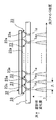
- FIG. 1A is a schematic diagram for explaining a cord contrast device according to a first embodiment of the present invention.
- FIG. 1B is a diagram illustrating a relationship between a portion to which stress is applied by the grating forming tool included in the core wire contrast device according to the first embodiment of the present invention and a refractive index change amount.
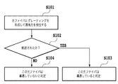
- FIG. 1C is a flowchart for performing the cardiac line contrast using the cardiac line contrast device according to the first embodiment of the present invention.
- FIG. 2A is a diagram schematically showing a single-mode optical fiber with holes having six holes.
- FIG. 2B is a diagram schematically showing a single-mode optical fiber with holes having ten holes.
- FIG. 3A is a graph showing the relationship between the wavelength and the loss spectrum according to the cord contrast device according to the first embodiment of the present invention.
- FIG. 3B is a graph showing the relationship between the period of the protrusion and the center wavelength (the wavelength at which the loss spectrum becomes the maximum value) related to the cord contrast device according to the first embodiment of the present invention.
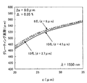
- FIG. 4 is a graph showing an example of the dependency of the grating period on the hole structure in the HAF, related to the core line contrast device according to the first embodiment of the present invention.
- FIG. 5A is a graph showing the relationship between the HAF core diameter 2a ( ⁇ m) and the grating period ( ⁇ m) related to the cord contrast device according to the first embodiment of the present invention.
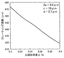
- FIG. 5B is a graph showing the relationship between the relative refractive index difference ⁇ (%) of HAF and the grating period ( ⁇ m) related to the cord control apparatus according to the first embodiment of the present invention.
- FIG. 6A is a graph showing the relationship between the normalized hole diameter d / 2a of HAF and the grating period ( ⁇ m) related to the cord contrast device according to the first embodiment of the present invention.
- FIG. 6B is a graph showing the relationship between the normalized hole diameter d / 2a and the grating period ( ⁇ m) related to the core wire contrast device according to the first embodiment of the present invention.
- FIG. 6C is a graph showing the relationship between the normalized hole diameter d / 2a and the grating period ( ⁇ m) related to the core wire contrast device according to the first embodiment of the present invention.
- FIG. 6D is a graph showing the relationship between the normalized hole diameter d / 2a and the grating period ( ⁇ m) related to the core wire contrast device according to the first embodiment of the present invention.
- FIG. 7 is a diagram illustrating a relationship between a portion to which stress is applied by the grating forming tool included in the core wire contrast device according to the first embodiment of the present invention and the amount of change in refractive index.
- FIG. 8 is a graph showing the relationship between the HAF standardized hole position c / 2a and the grating period in the cord contrast device according to the first embodiment of the present invention.
- FIG. 9A is a plan view for explaining another example of the grating forming tool provided in the core wire contrast device according to the first embodiment of the present invention.
- FIG. 9B is a side view for explaining another example of the grating forming tool provided in the core wire contrast device according to the first embodiment of the present invention.
- FIG. 9C is a diagram illustrating another example of the grating forming tool included in the optical fiber contrast device according to the first embodiment of the present invention, where the optical fiber position and the refractive index change amount when the optical fiber installation angle is 0 degrees; It is a figure which shows the relationship.
- FIG. 9A is a plan view for explaining another example of the grating forming tool provided in the core wire contrast device according to the first embodiment of the present invention.
- FIG. 9B is a side view for explaining another example of
- FIG. 9D shows another example of the grating forming tool provided in the optical fiber contrast device according to the first embodiment of the present invention, in which the optical fiber position and the refractive index change amount when the optical fiber installation angle is ⁇ . It is a figure which shows a relationship.
- FIG. 9E is a flowchart for performing core line contrast using another example of the grating forming tool provided in the fiber core contrast apparatus according to the first embodiment of the present invention.
- FIG. 10 is a graph showing a relationship between a wavelength and a loss spectrum according to another example of the grating forming tool included in the core wire contrast device according to the first embodiment of the present invention.
- FIG. 11 is a graph showing the relationship between the load F and the leakage light power when the grating is formed by the cord contrast device according to the first embodiment of the present invention.
- FIG. 12A is a diagram showing a case where the optical fiber bending device according to the second embodiment of the present invention includes one optical fiber bending imparting mechanism.
- FIG. 12B is a diagram showing a case where the optical fiber bending device according to the second embodiment of the present invention includes two optical fiber bending imparting mechanisms.
- FIG. 12C is a flowchart for performing cardiac contrast using the cardiac contrast device according to the second embodiment of the present invention.
- FIG. 13A is a diagram showing a relationship between a bending radius (mm) and a bending loss (dB) in the optical fiber bending imparting mechanism provided in the optical fiber contrast device according to the second embodiment of the present invention.
- FIG. 13B is a diagram showing the relationship between the bending radius (mm) and the leakage light power (dBm) in the optical fiber bending imparting mechanism provided in the optical fiber contrast device according to the second embodiment of the present invention.
- FIG. 14 is a diagram schematically showing a core wire contrast device according to a third embodiment of the present invention.
- FIG. 15 is a graph showing leakage light power and insertion loss at the time of grating formation in the core-line contrast device according to the third embodiment of the present invention.
- FIGS. 1A to 1C, 2A and 2B A first embodiment of a cord contrast device and method according to the present invention will be described with reference to FIGS. 1A to 1C, 2A and 2B. In this embodiment, a case where the present invention is applied to an optical fiber with improved bending loss characteristics will be described.
- FIG. 1A and FIG. 1B are views for explaining a core wire contrast device according to a first embodiment of the present invention
- FIG. 1A shows an outline thereof
- FIG. 1B shows a grating forming tool provided therein. The relationship between the location to which stress is applied and the amount of change in refractive index is shown.
- ⁇ 1 represents a propagation mode propagating through the optical fiber
- ⁇ 1 ′ represents leaked light leaked from the optical fiber.
- the core wire contrast device 100 includes a grating forming tool 20 (grating forming means), a light receiver 30 (light receiving means) and the like as shown in FIG. 1A.
- the light receiver 30 is a device that detects leakage light generated in the optical fiber 1.
- the grating forming tool 20 is a tool for forming a grating by applying a load F to the optical fiber 1 with a plurality of protrusions 23 (uneven portions).
- the grating forming tool 20 includes an optical fiber fixing tool 21, a stress applying tool 22, a protrusion 23, and the like.
- the optical fiber fixture 21 is an instrument that can fix the optical fiber 1 so that it cannot move in the axial direction of the optical fiber 1 and cannot move in the circumferential direction of the optical fiber.
- Examples of the optical fiber fixture 21 include a fixing base having a V-groove formed on the upper surface, and a pressing plate that presses and fixes the optical fiber arranged in the groove to the fixing base.
- the stress applying tool 22 is a rod-like or plate-like instrument, and has a plurality of protrusions 23 provided on the lower surface 22a of the instrument.
- the plurality of protrusions 23 are arranged such that the distance between the tip portions 23a of the adjacent protrusions 23 is a predetermined period ⁇ .
- the optical fiber 1 is an optical fiber having excellent bending loss characteristics, such as a single-mode optical fiber with holes (HAF), even if bending is applied to the optical fiber 1 without applying the load F shown in FIG. Since it does not occur, the light receiver 30 cannot detect leaked light.
- a load F is applied to the grating forming tool 20, as shown in FIG. 1B, a change in refractive index occurs at a predetermined location 1a of the optical fiber 1 in contact with the tip 23a of the projection 23. Since the tips 23a of the plurality of protrusions 23 are arranged with a predetermined period ⁇ , a long period grating in which a refractive index change occurs with the period ⁇ is formed.
- the propagation mode is converted to a higher-order mode when the period ⁇ and the wavelength ⁇ of the light wave satisfy the phase matching condition expressed by the following equation (1).
- n 0 denotes the effective refractive index of the propagating mode
- n m indicates the effective refractive index of the higher order mode.
- the higher-order mode generated by the conversion has much larger propagation loss and bending loss than the propagation mode. Therefore, a part of the propagation mode is converted into a higher-order mode by the grating forming tool 20 and the leaking higher-order mode is detected by the light receiver 30 so that the optical fiber is excellent in bending loss characteristics such as HAF. Can be realized. That is, a load F is applied to the optical fiber 1 with a plurality of protrusions 23 arranged at a predetermined period ⁇ to form a long-period grating with a period ⁇ on the optical fiber 1, and the leakage light generated thereby By detecting ⁇ 1 ′ with the light receiver 30, it can be determined that a light wave is conducted to the optical fiber 1.
- FIG. 1C shows a flowchart for performing the core contrast using the core contrast device according to the first embodiment of the present invention.
- leakage light is detected by applying a load to the grating forming tool of the fiber core contrast device (S101). At this time, if leakage light is detected (S102), it is determined that the optical fiber is conducting (S103). If no leakage light is detected (S102), it is determined that this optical fiber is not conducting (S104).
- FIG. 2A and FIG. 2B show an example of the structure of the HAF that is the subject of the core control of the present invention.
- the HAF includes a core portion 10, a clad portion 11 covering the periphery thereof, and six holes 12 provided at a predetermined distance from the core portion.
- HAF has a core, a clad, and a plurality of holes, and has excellent bending loss characteristics due to the confinement effect of holes and excellent connectivity with a conventional single mode fiber (SMF).
- SMF single mode fiber
- the core diameter 2a is in the range of 6.4 ⁇ m to 9.6 ⁇ m
- the relative refractive index difference ⁇ with respect to the cladding of the core is 0.3 to 0.55%
- the normalized hole position It is necessary that c / 2a is in the range of 2.0 to 4.5 and the normalized hole diameter d / 2a is 0.2 or more.
- FIG. 3A and 3B are diagrams for explaining the relationship between the period of the protrusion and the loss.
- FIG. 3A shows the wavelength and loss spectrum when the load F is 15.4 N and the period of the protrusion is 440 ⁇ m and 445 ⁇ m.
- FIG. 3B shows the relationship between the period of the protrusion and the center wavelength (the wavelength at which the loss spectrum becomes maximum).
- a solid line indicates a case where the period ⁇ of the protrusion is 440 ⁇ m
- a dotted line indicates a case where the period ⁇ of the protrusion is 445 ⁇ m.
- FIG. 3A it can be seen from the loss spectrum that optical loss occurs at a predetermined wavelength due to the formation of the grating.
- FIG. 3B it can be seen that when the period ⁇ of the protruding portion is increased, the center wavelength is decreased in inverse proportion to it. Therefore, it can be seen that the wavelength at which loss is generated can be controlled by changing the period ⁇ due to the period dependence of the center wavelength. From these facts, it is understood that an optical loss can be obtained at a desired wavelength by appropriately designing the grating period.
- FIG. 4 is a graph showing an example of the dependence of the grating period on the pore structure in the HAF, related to the cord contrast device according to the first embodiment of the present invention.
- the wavelength for performing the contrast control was 1550 nm
- the relative refractive index difference ⁇ 0.35%.
- the grating period increases monotonically as the position of the hole is further (away). It can be understood that the farther the holes are, the smaller the influence of the holes on the light wave is, and the closer to the SMF grating period.
- the grating period is increased by the same principle. It can be easily analogized that this relationship is the same in other core structures.
- FIG. 5A and FIG. 5B are graphs showing the core structure dependence of the grating period in HAF relating to the cord contrast device according to the first embodiment of the present invention.
- FIG. 5A shows the core diameter 2a ( ⁇ m) and The relationship between the grating period ( ⁇ m) is shown, and
- FIG. 5B shows the relationship between the relative refractive index difference ⁇ (%) and the grating period ( ⁇ m).
- the hole diameter d 2.7 ⁇ m
- the number of holes was 10.
- the core structure and the hole structure are designed between them, it can be easily understood that the grating period continuously changes between the values of these structures.
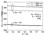
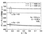
- FIG. 6A to 6D are graphs showing the relationship between the normalized hole diameter d / 2a and the grating period ( ⁇ m).
- FIG. 6D shows a case of a single mode optical fiber with a hole
- 6A to 6D show cases where the normalized hole positions c / 2a are 2.0 and 4.5, and the wavelengths ⁇ that are often used as test light are 1550 nm and 1650 nm.
- FIG. 7 is a schematic view of an example of a grating forming tool provided in the cord control device according to the first embodiment of the present invention.
- the grating forming tool 220 is provided with a plurality of protrusions 223 on the lower surface portion 222 a of the stress applying tool 222.
- the period of the plurality of protrusions 223 (the distance between the tip portions 223 a of the adjacent protrusions 223) changes in the longitudinal direction of the optical fiber 1. Specifically, the period between the adjacent tip portions 223a at the left end in the drawing in the plurality of protrusions 223 is ⁇ 1. On the other hand, the period between the front end portions 223a adjacent to the left end in the drawing in the plurality of protrusions 223 is ⁇ 2 (> ⁇ 1).
- the period between the tip portions 223a adjacent to each other in the plurality of projections 223 gradually increases from ⁇ 1 at the left end from the left side to the right side in the figure, and becomes ⁇ N at the right end.
- the period ⁇ of the plurality of protrusions 223 changes along the installation direction of the optical fiber 1. If the grating period changes from ⁇ 1 to ⁇ N at this time, optical loss can be generated at all operating wavelengths satisfying the phase matching condition for ⁇ 1 to ⁇ N. Thereby, a plurality of periods can be effectively realized simultaneously.
- the grating period required for HAF varies with the fiber structure. Since an optical fiber actually manufactured has a predetermined structural deviation, the grating period required for the HAF also varies.
- the configuration of FIG. 7 is preferable because variations due to structural deviation can be absorbed.
- the protrusions may be arranged so that the period of the protrusions gradually changes from 445 ⁇ m to 465 ⁇ m.
- the core line contrast of the holed single mode optical fiber (HAF) having various core structures and hole structures can be adjusted. It can be done reliably.
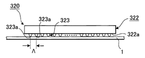
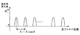
- FIG. 9A to FIG. 9D are views for explaining another example of the grating forming tool provided in the core wire contrast device according to the first embodiment of the present invention.
- FIG. 9A shows a plan view thereof
- FIG. 9C shows the relationship between the optical fiber position and the amount of change in refractive index when the optical fiber installation angle is 0 degrees
- FIG. 9D shows the optical fiber when the optical fiber installation angle is ⁇ . The relationship between a position and a refractive index change amount is shown.
- the grating forming tool 320 has a stress applying tool 322 having a substantially rectangular parallelepiped shape.
- a plurality of protrusions 323 are provided on the lower surface 322 a of the stress applying tool 322.
- the plurality of protrusions 323 are arranged at a predetermined period ⁇ along the longitudinal direction of the stress applying tool 322.
- a load is applied to the optical fiber 1 at a predetermined period ⁇ through the protrusion 323.
- the installation angle of the optical fiber 1 is ⁇ with respect to the longitudinal direction of the stress applying tool 322 (the arrangement direction of the plurality of protrusions 323), as shown in FIG. 9D, the plurality of protrusions 323 are provided.
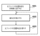
- FIG. 9E shows a flowchart for performing the core wire contrast using another example of the grating forming tool provided in the fiber core contrast device according to the first embodiment of the present invention.
- an optical fiber installation angle ⁇ is set to an initial value and arranged in this core wire contrast device (S201).
- the leak light from the optical fiber is detected by the core wire contrast device (S202).
- the detection of leaked light is repeated while increasing the installation angle of the optical fiber until sufficient leaked light is detected (S203).
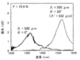
- FIG. 10 is a graph showing the relationship between the wavelength and the loss spectrum by the grating forming tool.
- the optical fiber has 10 holes, the mode field diameter and the bending loss at a wavelength of 1550 nm are 10.5 ⁇ m and 0.1 dB / turn or less (bending radius 5 mm). did.
- the load F applied to the stress applying tool was 15.4 N, and the period ⁇ of the plurality of protrusions provided on the stress applying tool was 500 ⁇ m.
- the loss spectrum becomes maximum at a wavelength of about 1360 nm.
- the period of the protrusions is 500 ⁇ m and the installation angle ⁇ of the optical fiber with respect to the arrangement direction of the plurality of protrusions is 20 degrees, it is the same as the case where the period ⁇ ′ of the protrusions is 532 ⁇ m. It can be seen that the loss spectrum becomes maximum at a wavelength of about 1560 nm.
- the effective grating period can be changed by using a grating forming tool having a plurality of protrusions arranged at the lower limit period ( ⁇ min) of the desired range. That is, assuming that the angle when the optical fiber is installed in the direction perpendicular to the arrangement direction of the plurality of protrusions is 0 degree, the effective grating period when the installation angle of the optical fiber is inclined by ⁇ is ⁇ min / cos ⁇ . Therefore, the effective grating period can be changed by changing the installation angle ⁇ of the optical fiber. Therefore, work efficiency can be improved.
- various cores can be obtained by changing the arrangement angle ⁇ of the optical fiber with respect to the arrangement direction of the plurality of protrusions and changing the effective grating period within the range of 0.24 mm to 0.75 mm. It is possible to reliably perform the core contrast of the single mode optical fiber (HAF) with a hole having a structure and a hole structure.
- HAF single mode optical fiber
- FIG. 11 is a graph showing the relationship between the load F and the leakage light power when the grating is formed by the cord contrast device according to the first embodiment of the present invention.
- the range in which the grating is formed is 4 cm in total length (88 protrusions)
- the input optical power was set to ⁇ 30 dBm.
- the minimum light receiving sensitivity of the light receiver was -80 dBm.
- the present invention when no load is applied (the present invention is not applied), it can be seen that leaked light cannot be detected by the light receiver. Further, it can be confirmed that the function of the grating can be strengthened by increasing the load, and the cord contrast can be realized by increasing the leakage light power. Furthermore, in the grating forming tool, it is preferable that the total load on all the protrusions is 8 N or more (the load per protrusion is 0.09 N or more), so that the leakage light power can be improved by 10 dB.
- FIGS. 12A and 12B A core wire contrast device according to a second embodiment of the present invention will be described with reference to FIGS. 12A and 12B.
- FIG. 12A and 12B are views for explaining a core wire contrast device according to a second embodiment of the present invention.
- FIG. 12A shows a case where one optical fiber bending imparting mechanism is provided, and FIG. The case where two optical fiber bending provision mechanisms are provided is shown.
- This embodiment is an apparatus in which an optical fiber bending imparting mechanism is added to the cord control apparatus according to the first embodiment described above.
- the same devices as those in the core wire contrast device according to the first embodiment described above are denoted by the same reference numerals, and the description thereof is omitted.
- the optical fiber contrast device 400 includes an optical fiber bending imparting mechanism 451 (optical fiber bend imparting means) for imparting a bend to the optical fiber 1, a grating forming tool 20, and a light receiver. 30 and the like.
- the optical fiber bending imparting mechanism 451 is a mechanism that can hold the optical fiber 1 in a state of being bent once with a predetermined radius of curvature R.
- the optical fiber bending imparting mechanism 451 is disposed immediately before the light receiver 30. That is, the optical fiber bending imparting mechanism 451 is disposed in the vicinity of the light receiver 30. Thereby, the light reception efficiency in the light receiver 30 is improved.
- the optical fiber bend imparting mechanism 451 since the higher order mode generated by the grating has a larger bending loss than the propagation mode, the presence of the optical fiber bend imparting mechanism 451 in the vicinity of the optical receiver 30 efficiently leaks the higher order mode. Can do.
- the optical fiber bending imparting mechanism 451 is preferable because the bending loss can be detected with respect to an optical fiber having a normal bending loss such as SMF, and the HAF and SMF core wires can be realized simultaneously by one unit.
- a cord contrast device 410 including a grating forming tool 20, a light receiver 30, optical fiber bending imparting mechanisms 452, 453, and the like.
- the optical fiber bending imparting mechanism 452 is a mechanism that can hold the optical fiber 1 in a state of being bent once with the first radius of curvature R1.
- the optical fiber bending imparting mechanism 453 is a mechanism that can hold the optical fiber 1 in a state of being bent once with a second curvature radius R2 different from the first curvature radius R1. Even the core wire contrast device 410 having such a configuration has the same effects as the above-described core wire contrast device 400.
- a two-fiber bend imparting mechanism can be a cord contrast device that is a mechanism that can hold an optical fiber with the same radius of curvature. It is also possible to provide a cord control device having three or more optical fiber bending imparting mechanisms. It is also possible to use a cord-contrast device in which the optical fiber bending imparting mechanism is disposed in the light receiver. Even if it is such a core wire contrast apparatus, there exists an effect similar to the core wire contrast apparatus which concerns on 2nd embodiment mentioned above.
- FIG. 12C shows a flowchart for performing the cardiac line contrast using the cardiac line contrast device according to the second embodiment of the present invention.
- FIGS. 13A and 13B are graphs showing optical characteristics of an optical fiber bending imparting mechanism provided in the optical fiber contrast device according to the second embodiment of the present invention.
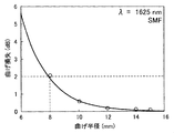
- FIG. 13A shows a bending radius (mm) and bending loss
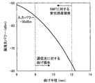
- FIG. 13B shows the relationship between the bending radius (mm) and the leakage light power (dBm). That is, FIGS. 13A and 13B show the insertion loss with respect to the bending radius of the optical fiber bending imparting mechanism and the detectable leakage light power related to the core wire contrast device according to the present embodiment. Since it is not always possible to determine whether or not the optical fiber for controlling the core is an optical fiber that is resistant to bending, excessive bending may occur, for example, if SMF is bent suddenly, and communication may be interrupted.
- FIG. 13A shows bending loss at 1625 nm on the longest wavelength side of the communication wavelength band in SMF as the most vulnerable condition to bending. As shown in FIG. 13A, by setting the bending radius to 8 mm or more, the bending loss can be set to 2 dB or less, which is preferable.
- FIG. 13B shows the leakage light power and the bending radius when the bending loss of the SMF is detected.
- the bending radius is preferably in the range of 8 mm to 12 mm.
- FIG. 14 is a diagram schematically showing a core wire contrast device according to a third embodiment of the present invention.
- the core wire contrast device is a device including the grating forming tool and the optical fiber bending imparting mechanism provided in the fiber core contrast device according to the second embodiment described above in the same instrument.
- the same device (light receiver 30) as that of the core wire contrast device according to the second embodiment described above is denoted by the same reference numeral, and the description thereof is omitted.
- the core wire contrast device 500 includes an optical fiber bending imparting mechanism 510, a grating forming tool 520 (grating forming means), a light receiver 30, and the like.
- the optical fiber bend imparting mechanism 510 includes a convex member 511 and a concave member 515.
- the convex member 511 includes one convex portion formed in an arc shape and a curved portion 512 including two concave portions that are smoothly connected to both sides of the convex portion.
- the convex member 511 is slidably disposed with respect to the concave member 515.
- the recess material 515 includes a first recess material 513 and a second recess material 514.
- the first concave member 513 and the second concave member 514 include curved portions 513a and 514a, respectively, and are formed in a shape that can sandwich the optical fiber with the curved portion 512.
- the grating forming tool 520 is composed of a plurality of protrusions 521 (uneven portions) provided on the entrance side curved portion 512a located on the entrance side (left side in the figure) in the light propagation direction in the curved portion 512 of the convex member 511.
- the grating forming tool 520 is installed in the optical fiber bending imparting mechanism 510.
- the plurality of protrusions 521 are arranged at a predetermined period (interval) ⁇ . Note that, in the curved portion 512 of the convex member 511, a plurality of protrusions are not provided on the outgoing curved portion 512b located on the outgoing side (right side in the drawing) in the light propagation direction.
- the optical fiber bending imparting mechanism 510 and the grating forming tool 520 can be integrated, and a core wire contrast device having a small size and good workability can be realized.
- FIG. 15 is a graph showing the leakage light power and insertion loss when the grating is formed.
- HAF hole positions
- the installation direction of the optical fiber (longitudinal direction of the optical fiber) is changed, and the applied load F is 0 to 20 N. It was. Further, the light receiver 30 was bent with a radius of curvature of 10 mm immediately before the light receiving element.
- the measurement wavelength and the input optical power were 1550 nm and ⁇ 10 dBm, respectively.
- the light beam contrast device and the core wire contrast method according to the present invention can be used for specifying an optical fiber during construction, maintenance, and operation of an optical line.
Landscapes
- Physics & Mathematics (AREA)
- General Physics & Mathematics (AREA)
- Chemical & Material Sciences (AREA)
- Analytical Chemistry (AREA)
- Optics & Photonics (AREA)
- Testing Of Optical Devices Or Fibers (AREA)
- Diffracting Gratings Or Hologram Optical Elements (AREA)
Abstract
Description
本発明に係る心線対照装置および方法の第一の実施形態につき図1Aから図1C、図2Aおよび図2Bを参照して説明する。本実施形態では、曲げ損失特性を改善した光ファイバに適用した場合について説明する。

ここで、突起部の周期と損失の関係について、図3Aおよび図3Bを参照して説明する。
ここで、HAFの空孔構造とグレーティング周期の関係の一例について、図4を参照して説明する。
図5Aおよび図5Bは、本発明の第一の実施形態に係る心線対照装置に係わる、HAFにおけるグレーティング周期のコア構造依存性を示すグラフであり、図5Aは、コア直径2a(μm)とグレーティング周期(μm)の関係を示し、図5Bは、比屈折率差Δ(%)とグレーティング周期(μm)の関係を示す。ここで、HAFの空孔構造はコア部を中心として対向する空孔間の距離c=18μmとし、空孔直径d=2.7μmとし、空孔数を10とした。
ここで、突起部の周期について、図6Aから図6Dを参照して説明する。
ここで、上述した本発明の第一の実施形態に係る心線対照装置が具備するグレーティング形成具の一例ついて図7を参照して説明する。
ここで、上述した本発明の第一の実施形態に係る心線対照装置が具備するグレーティング形成具の他例について図9Aから図9Dを参照して説明する。
ここで、荷重と漏洩光パワーとの関係について図11を参照して説明する。
本発明の第二の実施形態に係る心線対照装置について、図12Aおよび図12Bを参照して説明する。
ここで、上述した第二の実施形態に係る心線対照装置が具備する光ファイバ曲げ付与機構における曲げ半径と曲げ損失との関係について、図13Aおよび図13Bを参照して説明する。
本発明の第三の実施形態に係る心線対照装置について、図14を参照して説明する。
ここで、漏洩光パワーおよび挿入損失と荷重との関係について、図15を参照して説明する。
上記では、応力付与具に複数の突起部を設けた心線対照装置を用いて説明したが、光ファイバを固定する固定台に複数の突起部を設けた心線対照装置とすることも可能である。このような心線対照装置であっても、上述した第一、第二、第三の実施形態に係る心線対照装置と同様な作用効果を奏する。
Claims (9)
- 複数の突起部を以って光ファイバに荷重を与えることでグレーティングを形成するグレーティング形成手段と、
前記光ファイバで生じる漏洩光を検出する受光手段とを備える
ことを特徴とする心線対照装置。 - 前記複数の突起部の周期が、前記光ファイバの設置方向に沿って変化している
ことを特徴とする請求項1に記載の心線対照装置。 - 前記荷重が8N以上である
ことを特徴とする請求項1または請求項2に記載の心線対照装置。 - 前記光ファイバに対して曲げを付与する光ファイバ曲げ付与手段をさらに有し、
前記曲げの曲率半径が8mm~12mmの範囲内である
ことを特徴とする請求項1乃至請求項3の何れか一項に記載の心線対照装置。 - 前記複数の突起部が、0.24mm~0.75mmの範囲内の周期で配置されている
ことを特徴とする請求項1乃至請求項4の何れか一項に記載の心線対照装置。 - 前記複数の突起部が、前記光ファイバ曲げ付与手段に配置される
ことを特徴とする請求項4に記載の心線対照装置。 - 0.24mm~0.75mmの範囲内の周期で配置された複数の突起部を以って光ファイバに荷重を与えることで長周期グレーティングを形成し、
前記光ファイバで生じる漏洩光を検出することにより、前記光ファイバに光波が導通していることを判別する
ことを特徴とする心線対照方法。 - 前記複数の突起部と前記光ファイバとの角度を変えて、前記長周期グレーティングを形成することを特徴とする請求項7に記載の心線対照方法。
- 前記光ファイバに曲げを付与して、前記光ファイバで生じる漏洩光を検出することを特徴とする請求項7または8に記載の心線対照方法。
Priority Applications (3)
| Application Number | Priority Date | Filing Date | Title |
|---|---|---|---|
| JP2010525637A JPWO2010021207A1 (ja) | 2008-08-18 | 2009-06-30 | 心線対照装置および心線対照方法 |
| CN2009801310943A CN102119325A (zh) | 2008-08-18 | 2009-06-30 | 芯线检测设备和芯线检测方法 |
| US13/057,271 US20110141458A1 (en) | 2008-08-18 | 2009-06-30 | Coated Optical Fiber Identifying Apparatus and Coated Optical Fiber Identifying Method |
Applications Claiming Priority (2)
| Application Number | Priority Date | Filing Date | Title |
|---|---|---|---|
| JP2008-209478 | 2008-08-18 | ||
| JP2008209478 | 2008-08-18 |
Publications (1)
| Publication Number | Publication Date |
|---|---|
| WO2010021207A1 true WO2010021207A1 (ja) | 2010-02-25 |
Family
ID=41707086
Family Applications (1)
| Application Number | Title | Priority Date | Filing Date |
|---|---|---|---|
| PCT/JP2009/061976 Ceased WO2010021207A1 (ja) | 2008-08-18 | 2009-06-30 | 心線対照装置および心線対照方法 |
Country Status (4)
| Country | Link |
|---|---|
| US (1) | US20110141458A1 (ja) |
| JP (1) | JPWO2010021207A1 (ja) |
| CN (1) | CN102119325A (ja) |
| WO (1) | WO2010021207A1 (ja) |
Cited By (1)
| Publication number | Priority date | Publication date | Assignee | Title |
|---|---|---|---|---|
| JP2022162231A (ja) * | 2021-04-12 | 2022-10-24 | 古河電気工業株式会社 | 導光装置、光ファイバアセンブリ、および光学装置 |
Families Citing this family (4)
| Publication number | Priority date | Publication date | Assignee | Title |
|---|---|---|---|---|
| CN104913905A (zh) * | 2015-05-29 | 2015-09-16 | 成都亨通光通信有限公司 | 一种光纤弯曲损耗测定方法 |
| CN104913906A (zh) * | 2015-05-29 | 2015-09-16 | 成都亨通光通信有限公司 | 一种光纤弯曲损耗测定系统 |
| KR20190064964A (ko) * | 2017-12-01 | 2019-06-11 | 삼성전자주식회사 | 마이크로 스케일의 도파관 분광기 |
| CN109814247A (zh) * | 2019-03-28 | 2019-05-28 | 烽火通信科技股份有限公司 | 一种光纤传输干扰装置及干扰方法 |
Citations (4)
| Publication number | Priority date | Publication date | Assignee | Title |
|---|---|---|---|---|
| JP2006047678A (ja) * | 2004-08-04 | 2006-02-16 | Nippon Telegr & Teleph Corp <Ntt> | 帯域可変型光フィルタ |
| JP2006053559A (ja) * | 2004-08-09 | 2006-02-23 | Furukawa Electric North America Inc | 偏波不感微小曲げ光ファイバグレーティング、およびそれを使った装置 |
| JP2007309810A (ja) * | 2006-05-19 | 2007-11-29 | Nippon Telegr & Teleph Corp <Ntt> | 光ファイバ心線対照方法及びこれを使用する光ファイバ心線対照器 |
| JP2009063485A (ja) * | 2007-09-07 | 2009-03-26 | Nippon Telegr & Teleph Corp <Ntt> | 長周期グレーティングを用いた心線対照方法および装置 |
Family Cites Families (4)
| Publication number | Priority date | Publication date | Assignee | Title |
|---|---|---|---|---|
| JP2001159580A (ja) * | 1999-12-03 | 2001-06-12 | Sumitomo Electric Ind Ltd | 光ファイバの漏洩光検出装置および方法 |
| JP2002156564A (ja) * | 2000-09-05 | 2002-05-31 | Matsushita Electric Ind Co Ltd | 光信号読取装置 |
| JP4330073B2 (ja) * | 2005-04-04 | 2009-09-09 | 株式会社デンソー | 車両用衝突検出装置 |
| JP2007240389A (ja) * | 2006-03-09 | 2007-09-20 | Fujitsu Ltd | 光波形測定装置および光波形測定方法 |
-
2009
- 2009-06-30 CN CN2009801310943A patent/CN102119325A/zh active Pending
- 2009-06-30 US US13/057,271 patent/US20110141458A1/en not_active Abandoned
- 2009-06-30 WO PCT/JP2009/061976 patent/WO2010021207A1/ja not_active Ceased
- 2009-06-30 JP JP2010525637A patent/JPWO2010021207A1/ja active Pending
Patent Citations (4)
| Publication number | Priority date | Publication date | Assignee | Title |
|---|---|---|---|---|
| JP2006047678A (ja) * | 2004-08-04 | 2006-02-16 | Nippon Telegr & Teleph Corp <Ntt> | 帯域可変型光フィルタ |
| JP2006053559A (ja) * | 2004-08-09 | 2006-02-23 | Furukawa Electric North America Inc | 偏波不感微小曲げ光ファイバグレーティング、およびそれを使った装置 |
| JP2007309810A (ja) * | 2006-05-19 | 2007-11-29 | Nippon Telegr & Teleph Corp <Ntt> | 光ファイバ心線対照方法及びこれを使用する光ファイバ心線対照器 |
| JP2009063485A (ja) * | 2007-09-07 | 2009-03-26 | Nippon Telegr & Teleph Corp <Ntt> | 長周期グレーティングを用いた心線対照方法および装置 |
Cited By (2)
| Publication number | Priority date | Publication date | Assignee | Title |
|---|---|---|---|---|
| JP2022162231A (ja) * | 2021-04-12 | 2022-10-24 | 古河電気工業株式会社 | 導光装置、光ファイバアセンブリ、および光学装置 |
| JP7623202B2 (ja) | 2021-04-12 | 2025-01-28 | 古河電気工業株式会社 | 導光装置、光ファイバアセンブリ、および光学装置 |
Also Published As
| Publication number | Publication date |
|---|---|
| US20110141458A1 (en) | 2011-06-16 |
| JPWO2010021207A1 (ja) | 2012-01-26 |
| CN102119325A (zh) | 2011-07-06 |
Similar Documents
| Publication | Publication Date | Title |
|---|---|---|
| Hayashi et al. | Characterization of crosstalk in ultra-low-crosstalk multi-core fiber | |
| Hayashi et al. | Ultra-low-crosstalk multi-core fiber feasible to ultra-long-haul transmission | |
| US9088364B1 (en) | Optical transmission system and multi-core optical fiber | |
| JP4902799B2 (ja) | ダブルコア光ファイバ | |
| JP5855351B2 (ja) | マルチコアファイバ | |
| JP5498799B2 (ja) | 二重クラッドスタブファイバを備えたファイバ光学コネクタ | |
| US6535678B1 (en) | Multimode optical fiber with a higher order mode removing function | |
| US20140334789A1 (en) | Multi-core fiber | |
| JP5643855B2 (ja) | 高sbs閾値の光ファイバ | |
| JP5033290B2 (ja) | 分散勾配補償光導波路ファイバ | |
| US6711330B1 (en) | Optical transmission link with low bending loss | |
| JP5313079B2 (ja) | 光ファイバの特性評価方法 | |
| JP4101429B2 (ja) | 高次モード除去機能を有する多モード光ファイバ | |
| WO2010021207A1 (ja) | 心線対照装置および心線対照方法 | |
| US20120236295A1 (en) | Method of measuring bending performance of optical fiber | |
| EP2834687A1 (en) | Shunt fiber | |
| US20130094819A1 (en) | Optical transmission line | |
| JP6096268B2 (ja) | マルチコアファイバ | |
| JP5227152B2 (ja) | 光ファイバのシングルモード伝送の確認方法、カットオフ波長の測定方法および装置 | |
| JP7263056B2 (ja) | マルチコアファイバ、光コネクタ、ファンイン/ファンアウトデバイス | |
| JP7754186B2 (ja) | モード変換器及びモード変換器を含む光部品 | |
| JP5654506B2 (ja) | 心線対照方法及び心線対照装置 | |
| JP2014523546A (ja) | 1550nmの波長範囲における使用のためのファイバストレッチャモジュール | |
| JP2010032238A (ja) | 心線対照方法および装置 | |
| WO2008066659A2 (en) | High sbs threshold optical fiber |
Legal Events
| Date | Code | Title | Description |
|---|---|---|---|
| WWE | Wipo information: entry into national phase |
Ref document number: 200980131094.3 Country of ref document: CN |
|
| 121 | Ep: the epo has been informed by wipo that ep was designated in this application |
Ref document number: 09808143 Country of ref document: EP Kind code of ref document: A1 |
|
| WWE | Wipo information: entry into national phase |
Ref document number: 2010525637 Country of ref document: JP |
|
| WWE | Wipo information: entry into national phase |
Ref document number: 13057271 Country of ref document: US |
|
| NENP | Non-entry into the national phase |
Ref country code: DE |
|
| 122 | Ep: pct application non-entry in european phase |
Ref document number: 09808143 Country of ref document: EP Kind code of ref document: A1 |