WO2010010782A1 - 超音波診断装置とそのスキャン面の座標算出方法 - Google Patents
超音波診断装置とそのスキャン面の座標算出方法 Download PDFInfo
- Publication number
- WO2010010782A1 WO2010010782A1 PCT/JP2009/061565 JP2009061565W WO2010010782A1 WO 2010010782 A1 WO2010010782 A1 WO 2010010782A1 JP 2009061565 W JP2009061565 W JP 2009061565W WO 2010010782 A1 WO2010010782 A1 WO 2010010782A1
- Authority
- WO
- WIPO (PCT)
- Prior art keywords
- tomographic image
- ultrasonic
- subject
- coordinate system
- body contour
- Prior art date
- Legal status (The legal status is an assumption and is not a legal conclusion. Google has not performed a legal analysis and makes no representation as to the accuracy of the status listed.)
- Ceased
Links
Images






Classifications
-
- A—HUMAN NECESSITIES
- A61—MEDICAL OR VETERINARY SCIENCE; HYGIENE
- A61B—DIAGNOSIS; SURGERY; IDENTIFICATION
- A61B8/00—Diagnosis using ultrasonic, sonic or infrasonic waves
- A61B8/13—Tomography
- A61B8/14—Echo-tomography
-
- A—HUMAN NECESSITIES
- A61—MEDICAL OR VETERINARY SCIENCE; HYGIENE
- A61B—DIAGNOSIS; SURGERY; IDENTIFICATION
- A61B8/00—Diagnosis using ultrasonic, sonic or infrasonic waves
- A61B8/42—Details of probe positioning or probe attachment to the patient
- A61B8/4245—Details of probe positioning or probe attachment to the patient involving determining the position of the probe, e.g. with respect to an external reference frame or to the patient
- A61B8/4254—Details of probe positioning or probe attachment to the patient involving determining the position of the probe, e.g. with respect to an external reference frame or to the patient using sensors mounted on the probe
Definitions
- the present invention relates to an ultrasound diagnostic apparatus and a coordinate calculation method for a scan plane thereof, and more particularly to a technique suitable for making a diagnosis by comparing two tomographic images of the same cross section of a subject imaged at a time. .
- the ultrasonic diagnostic apparatus transmits and receives ultrasonic waves to and from the subject via the probe, and reconstructs and displays the tomographic image of the imaging region based on the reflected echo signal output from the probe, Diagnose the imaging site non-invasively and in real time.
- a tomographic image of the affected area (hereinafter referred to as a pre-treated tomographic image) taken before the treatment and an image taken during or after the treatment are used.
- a tomographic image of a diseased part (hereinafter referred to as a post-treatment tomographic image) is displayed in comparison and diagnosed.
- Patent Document 1 a pre-treatment tomogram is acquired as three-dimensional volume data associated with the subject coordinate system, and a treatment corresponding to the scan surface of the post-treatment tomogram is acquired from the acquired three-dimensional volume data.
- a method for extracting and displaying a pre-tomographic image in real time has been proposed.
- a specific part for example, a xiphoid process
- the tomographic image is searched at a position where the specific part is taken as a mark before the start of imaging of a post-treatment tomographic image.
- the stylus By moving the stylus, the subject coordinate systems before and after treatment are associated with each other.
- the ultrasonic tomographic image does not have the contour information of the body of the subject, it is difficult to estimate the position and inclination of the probe when the tomographic image is taken. Can be difficult.
- an object of the present invention is to easily match the display cross section of the tomographic image captured first and the ultrasonic tomographic image captured later.
- the ultrasonic diagnostic apparatus of the present invention generates ultrasonic tomographic image data based on an ultrasonic probe that transmits and receives ultrasonic waves to and from a subject, and a reflected echo signal received by the ultrasonic probe.
- a tomographic image data generation unit a position detector for detecting the position and inclination of the ultrasonic probe based on a sensor attached to the ultrasonic probe, and an ultrasonic signal generated based on the output of the position detector
- a tomographic image data storage unit that stores ultrasonic tomographic image data in association with a subject coordinate system set in advance on the subject, and an ultrasonic tomographic image and an ultrasonic probe based on the stored ultrasonic tomographic image data
- the subject contour information and the position information related to the specific part of the subject have a body contour model set in association with the body contour model coordinate system, and based on the position information related to the specific part of the subject,
- the coordinates of the scan plane of the real-time ultrasonic tomographic image are converted into the object coordinates. It is characterized in that it is calculated in association with the system.
- the ultrasonic diagnostic apparatus of the present invention includes a storage unit that stores the contour information of the subject and the positional information related to the specific part of the ultrasonic image of the subject in association with the body contour model coordinate system, and the identification of the subject Based on the positional information on the part, the object coordinate system and the body contour model coordinate system are associated with each other, and an ultrasonic tomographic image based on ultrasonic tomographic image data stored in the image storage unit, and an ultrasonic probe
- the object coordinate system when comparing the real-time ultrasonic tomographic image captured by the child with the body contour model coordinate system, the coordinates of the scan plane of the real-time ultrasonic tomographic image are determined as the object coordinates.
- a coordinate calculation unit for calculating in association with the system.
- the storage unit stores the contour information of the subject and the position information related to the specific part of the ultrasonic image of the subject in association with the body contour model coordinate system.
- the first step is performed, and the subject calculation system and the body contour model coordinate system are associated with each other based on the position information on the specific part of the subject by the coordinate calculation unit, and the ultrasound stored in the image storage unit By associating the object coordinate system and the body contour model coordinate system when comparing the ultrasonic tomographic image based on the tomographic image data and the real-time ultrasonic tomographic image captured by the ultrasonic probe, And a second step of calculating the coordinates of the scan plane of the real-time ultrasonic tomographic image in association with the subject coordinate system.
- a body contour model in which the contour information of the subject and the position information related to the specific part of the subject are set in association with the body contour model coordinate system is prepared in advance and stored in 100 million parts.
- the coordinates of the scan plane of the real-time ultrasonic tomographic image are the same as the object at the time of data storage. Since the calculation can be performed in association with the coordinate system, the display cross section of the tomographic image captured first and the ultrasonic tomographic image captured later can be easily matched.
- the present invention it is possible to easily match the display cross section of the tomographic image captured first and the ultrasonic tomographic image captured later.
- FIG. 3 is a conceptual diagram for designating at least three reference points that correlate with a specific part of a subject on a body contour model of the subject.
- FIG. 5 is a conceptual diagram of correspondence between the three-dimensional coordinates of each reference point in the body contour model coordinate system M and the three-dimensional coordinates of a corresponding part in the subject coordinate system P
- the conceptual diagram which preserve
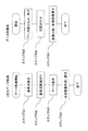
- the coordinates of each reference point in the body contour model coordinate system M and the coordinates correlated with each reference point in the subject coordinate system P ′ at the time of image comparison (when a post-treatment tomographic image is captured) are aligned.
- FIG. The figure which shows the example of a display of the image display apparatus at the time of comparing the tomogram before treatment and the tomogram after treatment.
- save, and a reconstruction process The conceptual diagram which preserve
- the coordinates of each reference point in the body contour model coordinate system M and the coordinates correlated with each reference point in the subject coordinate system P ′ at the time of image comparison (when a post-treatment tomographic image is captured) are aligned.
- FIG. The figure which shows the example of a display of the image display apparatus 32 at the time of comparing the tomogram before treatment and the tomogram after treatment.
- FIG. 1 is a diagram showing an overall schematic configuration of the ultrasonic diagnostic apparatus of the present embodiment.
- the ultrasound diagnostic apparatus 10 of the present embodiment includes an ultrasound probe 12 that transmits and receives ultrasound to and from a subject, a drive signal to the ultrasound probe 12, and an ultrasound probe.
- 12 includes an ultrasonic transmission / reception unit 14 that processes the reflected echo signal received at 12, and an ultrasonic signal conversion unit 16 that performs luminance modulation on the ultrasonic signal obtained from the ultrasonic transmission / reception unit 14.
- a position detector for detecting the position and tilt of the ultrasonic probe 12 a source source such as a transmitter, and a magnetic position attached to the ultrasonic probe 12 by sensing the magnetic field generated by the source source.
- a magnetic position sensor unit 18 including a sensor and the like is provided.
- an input unit 20 to which position information from the magnetic position sensor unit 18 is input is provided.
- the position detector is not limited to this, and various known techniques that can detect the position and inclination of the ultrasonic probe 12 can be used.
- the body contour model the contour information of the subject and the position information regarding the specific part of the subject are set in advance in association with the body contour model coordinate system.
- a tomographic image data control unit 26 for associating the coordinate system is provided.
- a reference image generation unit 28 that constructs a two-dimensional ultrasonic tomographic image (hereinafter referred to as a virtual tomographic image or a reference tomographic image as appropriate) based on information obtained from the tomographic image data control unit 26, and an ultrasonic signal
- a real-time two-dimensional image is constructed based on the signal generated by the converter 16 and is synthesized with the two-dimensional ultrasound tomogram (reference tomogram) constructed by the reference image generator 28.
- An image composition unit 30 and an image display device 32 such as a monitor for displaying an image synthesized by the image composition unit 30 are provided.
- the ultrasonic diagnostic apparatus of the present embodiment configured as described above displays, for example, a pre-treatment tomographic image and a post-treatment tomographic image in order to confirm the therapeutic effect of the affected part of the subject. Diagnose.
- the pre-treatment tomographic image is taken and the subject is ultrasonically scanned again after a few days, the post-treatment tomographic image having the same cross section as this is searched while viewing the pre-treatment tomographic image. It's not easy.
- the ultrasonic diagnostic apparatus according to the present embodiment easily matches the display cross section of the tomographic image captured first and the ultrasonic tomographic image captured later.
- the characteristic part of the ultrasonic diagnostic apparatus of this embodiment that achieves this object will be described for each example.
- three-dimensional volume data composed of a plurality of ultrasonic tomographic image data is stored in a storage means, and an ultrasonic tomographic image having the same cross section as the current ultrasonic scan plane is extracted from the stored three-dimensional volume data.
- This is an example of displaying together with a real-time ultrasonic tomographic image.
- FIG. 2 is a flowchart of the flow of acquisition, storage, and reconstruction processing of 3D volume data according to the present embodiment.
- FIG. 3 is a diagram illustrating a conceptual diagram and a display example in each process of the present embodiment.
- the body surface of the subject 40 is scanned with the ultrasound probe 12 equipped with the porcelain position sensor, and a continuous two-dimensional ultrasound tomographic image is acquired (step 201), Three-dimensional volume data is created from a plurality of two-dimensional ultrasonic tomographic images (step 202).
- the following data saving process is started (step 203).
- the body contour model 42 of the subject created in advance and stored in the storage means is displayed on the image display device 32, for example, a user such as a doctor or a laboratory technician.
- a user such as a doctor or a laboratory technician
- at least three reference points 44 that correlate with specific parts of the subject are designated (set) on the body contour model (step 204).
- the body contour model may be prepared for each type of adult / child, male / female, etc. These can be selected by a pull-down menu. Further, for example, it can be prepared for each part of the subject such as the neck, heart, abdomen, and lower limbs. When these are selected, the body contour model 42 corresponding to the selection is displayed in the display area 46. A body contour model can also be prepared for each ultrasonic probe. In addition, the body contour model can be rotated in the display area 46.
- the user sets a reference point on the body contour model 42. For example, after pressing the reference point 1 button in the reference point setting menu 48, manually specifying the reference point 44 on the body contour model 42, and inputting the detailed information of this reference point 44 into the detailed information input field
- the reference point can be set by repeating 3 times.
- a specific part of a subject for which a reference point can be set using a pull-down menu is prepared in advance, and when the user designates a specific part on the pull-down menu, the body contour is automatically corresponding to this. It is also possible to set a reference point on the model 42 and input detailed information.
- the body contour model and the subject are subsequently associated with the position information of the three points specified in step 204 (step 205).
- a real-time ultrasonic tomographic image is displayed in the display area 47 for reference for associating the body contour model with the subject, and a specific part of the subject (for example, a xiphoid process) is imaged at a position.
- the correlation with the specific part of the subject e.g., the coordinate of the ultrasonic probe
- the specific part of the body contour model are correlated.
- Can be associated with the coordinates to be performed for example, coordinates on the body contour).
- the body contour model coordinate system M and the object coordinate system P at the time of data storage are associated, and the relative relationship between the two can be grasped.
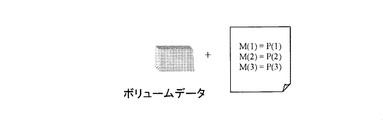
- the associated position information (association of coordinates indicating the relative relationship between the body contour model coordinate system M and the subject coordinate system P) and the volume data are stored (step 206). For example, this can be done by pressing a save button in the reference point setting menu 48.
- the stored position information and 3D volume data are read (step 207), and the 3D volume data is reconstructed (step 208).
- a two-dimensional image (reference tomogram) of an arbitrary cross section is constructed from the three-dimensional volume data (step 209), body contour model 42, position information, body contour model 42 from the reference tomogram, reference point 44,
- a reference image is created by combining the ultrasonic scan plane passing through the reference point and the reference tomographic image on the scan plane (step 210).
- the reference tomographic image and the reference image are displayed on the image display device 32 (step 211). Specifically, for example, as shown in FIG. 3F, a reference tomographic image is displayed in the display area 50, and a reference image is displayed in the display area 52.
- FIG. 3F shows the coordinates of each reference point in the body contour model coordinate system M and the coordinates correlated with each reference point in the subject coordinate system P ′ when the image is compared (when a post-treatment tomographic image is captured).
- 4 is a display example of the image display device 32 when positioning is performed.
- the cross sections of the reference tomographic image and the reference image are appropriately switched (step 212), and steps 209 to 211 are repeated each time the switching is performed.
- the image display device 32 is provided with a button 55 for selecting each reference point in the alignment menu 56 and each button 57 for selecting AXIAL, COEONAL, and SAGITTAL.
- the cross section of the reference tomographic image to be displayed and the cross section of the reference image can be switched by selecting the cross section in the direction.
- the display area 53 the conditions of the stored data are displayed.
- the user aligns the ultrasonic tomographic image and the reference tomographic image captured in real time while referring to the reference image and the reference tomographic image (step 213). Specifically, scanning is performed while changing the position of the ultrasound probe 12 so that the real-time ultrasound tomogram displayed in the display area 54 becomes the same image as the reference tomogram displayed in the display area 50. To do.
- the body contour model having the body contour information of the subject is displayed for reference, and the ultrasound scan plane on which the reference tomographic image is reconstructed is displayed on the body contour model. . Therefore, since the user can visually grasp which tomographic plane of the subject the reference tomographic image displayed in the display area 50 is, it is easy to search for a real-time ultrasonic tomographic image similar to the reference tomographic image. is there.
- the operation of pressing the setting button in the alignment menu 56 is performed for each reference point.
- This associates the coordinates of each reference point in the body contour model coordinate system M with the coordinates that correlate to each reference point in the subject coordinate system P ′ at the time of image comparison (when a post-treatment tomographic image is captured).
- the body contour model coordinate system M and the current subject coordinate system P ′ are associated with each other, and the relative relationship between the two is grasped.
- the OK button on the image display device 32 is pressed to move to a mode for comparing the pre-treatment tomographic image and the post-treatment tomographic image.
- FIG. 4 is a diagram showing a display example of the image display device 32 when comparing the pre-treatment tomogram and the post-treatment tomogram.
- the left side of the display is a past image (reference tomographic image cut out from three-dimensional volume data), and the right side of the display is a current image (real-time ultrasonic tomographic image).
- a reference image obtained by combining the body contour model, each reference point, the ultrasonic scan plane, and the reference tomographic image on the scan plane may be displayed together with the past image.
- the user can always refer to a past image having the same cross section as the real-time ultrasonic tomographic image while arbitrarily scanning the subject with the ultrasonic probe. Therefore, it is possible to easily diagnose the state of the affected part of the subject before and after treatment.
- the display cross section of the tomographic image captured first and the ultrasonic tomographic image captured later can be easily matched.
- the storage means instead of the three-dimensional volume data composed of a plurality of ultrasonic tomographic image data, one piece or a plurality of ultrasonic tomographic data not constituting the three-dimensional volume data are stored in the storage means, and the stored ultrasonic tomography In this embodiment, the position of the ultrasonic probe is guided in order to display a real-time ultrasonic tomographic image having the same cross section as the image data.
- different parts from the first embodiment will be mainly described, and description of overlapping parts will be omitted as appropriate.
- FIG. 5 is a flowchart of the flow of acquisition, storage, and reconstruction processing of the two-dimensional ultrasonic tomographic image data according to the present embodiment.
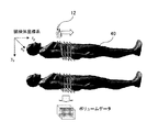
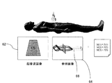
- FIG. 6 is a diagram illustrating a conceptual diagram and a display example in each process of the present embodiment.
- step 501 three characteristic points on the body contour model 42 are designated by the same operation as in the first embodiment (step 501), and the body contour model and the subject are associated with the position information of the three points designated in step 501 ( Step 502).
- arbitrary ultrasonic tomographic data is selected from the captured ultrasonic tomographic data, and the selected ultrasonic tomographic data 62 and associated positional information (body contour model coordinate system M And the reference image 64 are stored (association of coordinates indicating a relative relationship between the data and the object coordinate system P at the time of data storage) (steps 503 and 504).
- the reference image 64 includes a body contour model 42, a scan plane of the ultrasonic tomographic data 62, an ultrasonic tomographic image on the scan plane, and the like.
- the stored ultrasonic tomographic data and reference image are read, and as shown in FIG. 6B, the ultrasonic tomographic image, the body contour model, and each reference point on the model are displayed (step 505). Subsequently, the stored reference point is associated with the position information while referring to the ultrasonic tomogram by the user (step 506).
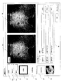
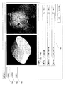
- FIG. 7 is a diagram showing a display example of the image display device 32 when comparing a pre-treatment tomogram and a post-treatment tomogram.
- the left side of the display is a past image
- the right side of the display shows a current image (real-time ultrasonic tomographic image).
- a reference image obtained by combining the body contour model, each reference point, the ultrasonic scan plane, and the reference tomographic image on the scan plane may be displayed together with the past image.
- the reference image is displayed together with the past image, and the past image (pre-treatment tomogram) and the current image (post-treatment tomogram) are compared (step 507). Specifically, when there are multiple stored ultrasonic tomographic data, the ultrasonic tomographic data to be compared is selected from the pull-down menu 70, and an ultrasonic tomographic image based on the selected ultrasonic tomographic data is displayed. Is done.
- a guide display 72 is made to move the ultrasonic probe to a position where a real-time ultrasonic tomographic image having the same cross section as the layer image data can be taken. Specifically, a message such as “is shifted in the XX direction” or “Please move in the XX direction” is displayed.
- the user moves the ultrasound probe 12 according to this guide display. Then, when the position of the ultrasound probe 12 is aligned with the same cross section as the stored ultrasound tomographic data, this is indicated in the guide display, and in this state, the pre-treatment tomogram and the post-treatment tomogram are compared. It is.
- the user can compare the body contour model coordinate system M with the subject coordinate system at the time of image comparison. Positioning with P ′ can be facilitated. As a result, the relative relationship between the subject coordinate system P at the time of data storage and the subject coordinate system P ′ at the time of image comparison is grasped in association with the body contour model coordinate system M, and the ultrasonic tomography before treatment
- An ultrasonic probe position guide for obtaining a real-time ultrasonic tomographic image having the same cross section as the image can be provided. Therefore, it is possible to easily match the display cross sections of the tomographic image captured first and the ultrasonic tomographic image captured later.
- the case where ultrasonic scanning is performed in a state where the subject is on his / her back is described as an example, but the present invention is not limited thereto. If the subject is in the same posture at the time of pre-treatment data storage and confirmation of the effect after treatment, the subject coordinates are the same as in the first and second embodiments in any posture such as sideways or prone By associating the systems P and P ′, the relative positional relationship between them can be grasped.
- the tomographic data storage unit includes means for setting reference points regarding at least three specific parts of the subject on the contour of the body contour model displayed on the image display, and each reference set on the body contour model.
- the stored ultrasonic tomographic image data is three-dimensional volume data composed of a plurality of ultrasonic tomographic image data, it corresponds to the scan plane coordinates of the real-time ultrasonic tomographic image calculated by the tomographic image data control unit.
- a reference image generation unit that extracts tomogram data from three-dimensional volume data and generates a reference tomogram
- an image synthesis unit that synthesizes a real-time ultrasonic tomogram and a reference tomogram
- a synthesized real-time ultrasonic tomogram An ultrasonic diagnostic apparatus can be configured by including an image display that displays a reference tomographic image.
- the user can always refer to a reference tomographic image (past image) having the same cross section as the real-time ultrasonic tomographic image while arbitrarily scanning the subject with the ultrasonic probe. Therefore, for example, the state before and after the treatment of the affected part of the subject can be easily diagnosed.
- An ultrasonic diagnostic apparatus comprising means for calculating a moving direction of an ultrasonic probe for superimposing a scan plane on a tomographic plane of stored ultrasonic tomographic image data and displaying it on an image display Good.
- the stored ultrasonic tomographic image data is not one of the three-dimensional volume data but one or a plurality of two-dimensional ultrasonic tomographic image data
- the stored ultrasonic tomographic image data is not one of the three-dimensional volume data but one or a plurality of two-dimensional ultrasonic tomographic image data
Landscapes
- Life Sciences & Earth Sciences (AREA)
- Health & Medical Sciences (AREA)
- Biomedical Technology (AREA)
- Biophysics (AREA)
- Nuclear Medicine, Radiotherapy & Molecular Imaging (AREA)
- Pathology (AREA)
- Radiology & Medical Imaging (AREA)
- Engineering & Computer Science (AREA)
- Physics & Mathematics (AREA)
- Heart & Thoracic Surgery (AREA)
- Medical Informatics (AREA)
- Molecular Biology (AREA)
- Surgery (AREA)
- Animal Behavior & Ethology (AREA)
- General Health & Medical Sciences (AREA)
- Public Health (AREA)
- Veterinary Medicine (AREA)
- Ultra Sonic Daignosis Equipment (AREA)
Abstract
Description
特に、被検体の輪郭情報及び被検体の特定部位に関する位置情報が体輪郭モデル座標系に対応付けて設定された体輪郭モデルを有しており、被検体の特定部位に関する位置情報に基づいて、被検体座標系と体輪郭モデル座標系とを対応づけるとともに画像対比時の被検体座標系と体輪郭モデル座標系とを対応づけることにより、リアルタイム超音波断層像のスキャン面の座標を被検体座標系に対応づけて算出することを特徴とする。
Claims (7)
- 被検体の輪郭情報及び被検体の超音波画像の特定部位に関する位置情報を体輪郭モデル座標系に対応付けて記憶する記憶部と、
前記被検体の特定部位に関する位置情報に基づいて、前記被検体座標系と前記体輪郭モデル座標系とを対応づけるとともに、画像保存部に保存された超音波断層像データに基づく超音波断層像と、超音波探触子により撮像されるリアルタイム超音波断層像とを対比する際の被検体座標系と前記体輪郭モデル座標系とを対応づけることにより、前記リアルタイム超音波断層像のスキャン面の座標を前記被検体座標系に対応づけて算出する座標算出部と、
を備えたことを特徴とする超音波診断装置。 - 被検体との間で超音波の送受信を行う超音波探触子と、
該超音波探触子で受信された反射エコー信号に基づいて超音波断層像データを生成する断層像データ生成部と、
前記超音波探触子に取り付けられたセンサーに基づき超音波探触子の位置及び傾きを検出する位置検出器と、
該位置検出器の出力に基づいて、前記生成された超音波断層像データを前記被検体に予め設定されている被検体座標系に対応付けて保存する断層像データ保存部と、保存された超音波断層像データに基づく超音波断層像と前記超音波探触子により撮像されるリアルタイム超音波断層像とを対比する際に、前記位置検出器の出力に基づいて、被検体に予め設定されている画像対比時の被検体座標系におけるリアルタイム超音波断層像のスキャン面の座標を前記被検体座標系に対応づけて算出する断層像データ制御部とを備えてなる超音波診断装置であって、
前記被検体の輪郭情報及び前記被検体の特定部位に関する位置情報が体輪郭モデル座標系に対応付けて設定された体輪郭モデルを有し、前記被検体の特定部位に関する位置情報に基づいて、前記被検体座標系と前記体輪郭モデル座標系とを対応づけるとともに前記画像対比時の被検体座標系と前記体輪郭モデル座標系とを対応づけることにより、前記リアルタイム超音波断層像のスキャン面の座標を前記被検体座標系に対応づけて算出する座標算出部を備えたことを特徴とする超音波診断装置。 - 画像表示器に表示される前記体輪郭モデルの輪郭上に少なくとも3点の前記被検体の特定部位に関する基準点を設定する基準点設定部を備え、前記断層データ保存部は、体輪郭モデル上に設定された各基準点の前記体輪郭モデル座標系における座標と前記被検体の前記各基準点に対応する部位の前記被検体座標系における座標とを関連付けて保存し、前記座標算出部は、前記体輪郭モデル上に設定された各基準点の前記体輪郭モデル座標系における座標と、前記被検体の前記各基準点に対応する部位の前記画像対比時の被検体座標系における座標とを関連付けて前記リアルタイム超音波断層像のスキャン面の座標を算出する請求項2に記載の超音波診断装置。
- 前記保存された超音波断層像データは、複数の超音波断層像データからなる3次元ボリュームデータであり、前記断層像データ制御部により算出された前記リアルタイム超音波断層像のスキャン面の座標に対応した断層像データを前記3次元ボリュームデータから抽出してリファレンス断層像を生成するリファレンス画像生成部と、前記リアルタイム超音波断層像と前記リファレンス断層像を合成する画像合成部と、合成された前記リアルタイム超音波断層像と前記リファレンス断層像とを表示する画像表示器とを備えた請求項2に記載の超音波診断装置。
- 前記保存された超音波断層像データの断層面の座標と、前記断層像データ制御部により算出された前記リアルタイム超音波断層像のスキャン面の座標とに基づいて、前記算出された前記リアルタイム超音波断層像のスキャン面を前記保存された超音波断層像データの断層面に重ねるための前記超音波探触子の移動方向を算出して前記画像表示器に表示制御する表示制御部とを備えた請求項2に記載の超音波診断装置。
- 前記体輪郭モデルと、該体輪郭モデルの輪郭上に設定された前記各基準点と、前記体輪郭モデルの前記基準点を通る超音波断層像のスキャン面と、該スキャン面における超音波断層像とを表示した請求項2乃至5の何れか一項に記載の超音波診断装置。
- 記憶部により被検体の輪郭情報及び被検体の超音波画像の特定部位に関する位置情報を体輪郭モデル座標系に対応付けて記憶する第1工程と、
座標算出部により前記被検体の特定部位に関する位置情報に基づいて、前記被検体座標系と前記体輪郭モデル座標系とを対応づけるとともに、画像保存部に保存された超音波断層像データに基づく超音波断層像と、超音波探触子により撮像されるリアルタイム超音波断層像とを対比する際の被検体座標系と前記体輪郭モデル座標系とを対応づけることにより、前記リアルタイム超音波断層像のスキャン面の座標を前記被検体座標系に対応づけて算出する第2工程と、
を含むことを特徴とする超音波診断装置のスキャン面の座標算出方法。
Priority Applications (2)
| Application Number | Priority Date | Filing Date | Title |
|---|---|---|---|
| US13/054,859 US20110144500A1 (en) | 2008-07-22 | 2009-06-25 | Ultrasonic diagnostic apparatus and method for calculating coordinates of scanned surface thereof |
| JP2010521653A JP5416109B2 (ja) | 2008-07-22 | 2009-06-25 | 超音波診断装置とそのスキャン面の座標算出方法 |
Applications Claiming Priority (2)
| Application Number | Priority Date | Filing Date | Title |
|---|---|---|---|
| JP2008189225 | 2008-07-22 | ||
| JP2008-189225 | 2008-07-22 |
Publications (1)
| Publication Number | Publication Date |
|---|---|
| WO2010010782A1 true WO2010010782A1 (ja) | 2010-01-28 |
Family
ID=41570248
Family Applications (1)
| Application Number | Title | Priority Date | Filing Date |
|---|---|---|---|
| PCT/JP2009/061565 Ceased WO2010010782A1 (ja) | 2008-07-22 | 2009-06-25 | 超音波診断装置とそのスキャン面の座標算出方法 |
Country Status (3)
| Country | Link |
|---|---|
| US (1) | US20110144500A1 (ja) |
| JP (1) | JP5416109B2 (ja) |
| WO (1) | WO2010010782A1 (ja) |
Cited By (4)
| Publication number | Priority date | Publication date | Assignee | Title |
|---|---|---|---|---|
| JP2011229547A (ja) * | 2010-04-23 | 2011-11-17 | Ge Medical Systems Global Technology Co Llc | 超音波診断装置 |
| WO2012164892A1 (ja) * | 2011-05-30 | 2012-12-06 | パナソニック株式会社 | 超音波診断装置および超音波を用いた画像取得方法 |
| US9524551B2 (en) | 2012-09-03 | 2016-12-20 | Toshiba Medical Systems Corporation | Ultrasound diagnosis apparatus and image processing method |
| JP2018000775A (ja) * | 2016-07-07 | 2018-01-11 | 東芝メディカルシステムズ株式会社 | 超音波診断装置、及び医用画像処理装置 |
Families Citing this family (8)
| Publication number | Priority date | Publication date | Assignee | Title |
|---|---|---|---|---|
| JP5538862B2 (ja) * | 2009-12-18 | 2014-07-02 | キヤノン株式会社 | 画像処理装置、画像処理システム、画像処理方法、及びプログラム |
| JP5863330B2 (ja) * | 2011-08-22 | 2016-02-16 | 国立大学法人旭川医科大学 | 画像処理装置、画像処理方法、およびプログラム |
| JP6205709B2 (ja) * | 2012-10-30 | 2017-10-04 | セイコーエプソン株式会社 | 超音波測定装置 |
| US10025272B2 (en) * | 2013-01-25 | 2018-07-17 | General Electric Company | Ultrasonic holography imaging system and method |
| KR101595718B1 (ko) * | 2014-02-04 | 2016-02-19 | 한국디지털병원수출사업협동조합 | 3차원 초음파 프로브의 스캔 위치 가이드 방법 및 이 방법이 포함된 초음파 진단기 |
| JP6840481B2 (ja) * | 2016-07-19 | 2021-03-10 | キヤノン株式会社 | 画像処理装置および画像処理方法 |
| JP6929028B2 (ja) * | 2016-07-29 | 2021-09-01 | キヤノン株式会社 | 測距型センサを用いて人を検知する装置、方法及びプログラム |
| KR102144671B1 (ko) * | 2020-01-16 | 2020-08-14 | 성균관대학교산학협력단 | 증강현실 안경을 활용한 인공지능형 초음파 자가 진단을 위한 초음파 스캐너 자세 교정 장치 및 이를 이용한 원격 의료 진단 방법 |
Citations (4)
| Publication number | Priority date | Publication date | Assignee | Title |
|---|---|---|---|---|
| JPH0428354A (ja) * | 1990-05-25 | 1992-01-30 | Toshiba Corp | 超音波診断装置 |
| JP2005296436A (ja) * | 2004-04-14 | 2005-10-27 | Hitachi Medical Corp | 超音波診断装置 |
| JP2006271588A (ja) * | 2005-03-29 | 2006-10-12 | Hitachi Medical Corp | 超音波装置 |
| WO2007040270A1 (ja) * | 2005-10-06 | 2007-04-12 | Hitachi Medical Corporation | 穿刺治療支援装置 |
Family Cites Families (5)
| Publication number | Priority date | Publication date | Assignee | Title |
|---|---|---|---|---|
| US6405072B1 (en) * | 1991-01-28 | 2002-06-11 | Sherwood Services Ag | Apparatus and method for determining a location of an anatomical target with reference to a medical apparatus |
| JP4088104B2 (ja) * | 2002-06-12 | 2008-05-21 | 株式会社東芝 | 超音波診断装置 |
| EP1551510A1 (en) * | 2002-10-07 | 2005-07-13 | Nomos Corporation | Method and apparatus for target position verification |
| EP2460474B1 (en) * | 2003-05-08 | 2015-12-16 | Hitachi Medical Corporation | Reference image display method for ultrasonography and ultrasonic diagnosis apparatus |
| US7840253B2 (en) * | 2003-10-17 | 2010-11-23 | Medtronic Navigation, Inc. | Method and apparatus for surgical navigation |
-
2009
- 2009-06-25 US US13/054,859 patent/US20110144500A1/en not_active Abandoned
- 2009-06-25 JP JP2010521653A patent/JP5416109B2/ja not_active Expired - Fee Related
- 2009-06-25 WO PCT/JP2009/061565 patent/WO2010010782A1/ja not_active Ceased
Patent Citations (4)
| Publication number | Priority date | Publication date | Assignee | Title |
|---|---|---|---|---|
| JPH0428354A (ja) * | 1990-05-25 | 1992-01-30 | Toshiba Corp | 超音波診断装置 |
| JP2005296436A (ja) * | 2004-04-14 | 2005-10-27 | Hitachi Medical Corp | 超音波診断装置 |
| JP2006271588A (ja) * | 2005-03-29 | 2006-10-12 | Hitachi Medical Corp | 超音波装置 |
| WO2007040270A1 (ja) * | 2005-10-06 | 2007-04-12 | Hitachi Medical Corporation | 穿刺治療支援装置 |
Cited By (4)
| Publication number | Priority date | Publication date | Assignee | Title |
|---|---|---|---|---|
| JP2011229547A (ja) * | 2010-04-23 | 2011-11-17 | Ge Medical Systems Global Technology Co Llc | 超音波診断装置 |
| WO2012164892A1 (ja) * | 2011-05-30 | 2012-12-06 | パナソニック株式会社 | 超音波診断装置および超音波を用いた画像取得方法 |
| US9524551B2 (en) | 2012-09-03 | 2016-12-20 | Toshiba Medical Systems Corporation | Ultrasound diagnosis apparatus and image processing method |
| JP2018000775A (ja) * | 2016-07-07 | 2018-01-11 | 東芝メディカルシステムズ株式会社 | 超音波診断装置、及び医用画像処理装置 |
Also Published As
| Publication number | Publication date |
|---|---|
| JPWO2010010782A1 (ja) | 2012-01-05 |
| JP5416109B2 (ja) | 2014-02-12 |
| US20110144500A1 (en) | 2011-06-16 |
Similar Documents
| Publication | Publication Date | Title |
|---|---|---|
| JP5416109B2 (ja) | 超音波診断装置とそのスキャン面の座標算出方法 | |
| JP5348889B2 (ja) | 穿刺治療支援装置 | |
| JP5225401B2 (ja) | 超音波診断装置 | |
| JP4470187B2 (ja) | 超音波装置、超音波撮像プログラム及び超音波撮像方法 | |
| JP5738507B2 (ja) | 超音波プローブの軌跡表現装置及び超音波診断装置 | |
| JP5322600B2 (ja) | 超音波診断装置 | |
| JP6282934B2 (ja) | 超音波診断装置及び医用画像診断装置 | |
| WO2014077396A1 (ja) | 超音波診断装置及び画像処理方法 | |
| JP2011015952A (ja) | 超音波診断装置、画像処理装置、画像処理方法および画像表示方法 | |
| JP2015000132A (ja) | 超音波診断装置 | |
| JP2010166973A (ja) | 超音波診断装置および位置情報取得プログラム | |
| JP5462076B2 (ja) | 超音波診断装置および画像情報管理装置 | |
| JP2005296436A (ja) | 超音波診断装置 | |
| JPWO2012164892A1 (ja) | 超音波診断装置および超音波を用いた画像取得方法 | |
| JP2013255658A (ja) | 超音波診断装置 | |
| JP2018079070A (ja) | 超音波診断装置、及び走査支援プログラム | |
| JP6720001B2 (ja) | 超音波診断装置、及び医用画像処理装置 | |
| JP2008100094A (ja) | 超音波診断装置 | |
| CN117770875A (zh) | 超声波诊断装置及超声波诊断装置的控制方法 | |
| JP4379211B2 (ja) | 超音波診断装置 | |
| WO2007069650A1 (ja) | 超音波診断装置 | |
| CN110914916A (zh) | 用于监测evar后患者的成像方法、控制器和成像系统 | |
| JP2017080510A (ja) | 超音波診断装置 | |
| JP2023156099A (ja) | 超音波診断装置 | |
| KR101538423B1 (ko) | 초음파 영상 장치 및 그 제어 방법 |
Legal Events
| Date | Code | Title | Description |
|---|---|---|---|
| 121 | Ep: the epo has been informed by wipo that ep was designated in this application |
Ref document number: 09800297 Country of ref document: EP Kind code of ref document: A1 |
|
| WWE | Wipo information: entry into national phase |
Ref document number: 2010521653 Country of ref document: JP |
|
| WWE | Wipo information: entry into national phase |
Ref document number: 13054859 Country of ref document: US |
|
| NENP | Non-entry into the national phase |
Ref country code: DE |
|
| 122 | Ep: pct application non-entry in european phase |
Ref document number: 09800297 Country of ref document: EP Kind code of ref document: A1 |