WO2010010688A1 - 処理装置の作動監視システム - Google Patents
処理装置の作動監視システム Download PDFInfo
- Publication number
- WO2010010688A1 WO2010010688A1 PCT/JP2009/003413 JP2009003413W WO2010010688A1 WO 2010010688 A1 WO2010010688 A1 WO 2010010688A1 JP 2009003413 W JP2009003413 W JP 2009003413W WO 2010010688 A1 WO2010010688 A1 WO 2010010688A1
- Authority
- WO
- WIPO (PCT)
- Prior art keywords
- vibration
- waveform
- processing apparatus
- event data
- control
- Prior art date
- Legal status (The legal status is an assumption and is not a legal conclusion. Google has not performed a legal analysis and makes no representation as to the accuracy of the status listed.)
- Ceased
Links
Images


Classifications
-
- H—ELECTRICITY
- H10—SEMICONDUCTOR DEVICES; ELECTRIC SOLID-STATE DEVICES NOT OTHERWISE PROVIDED FOR
- H10P—GENERIC PROCESSES OR APPARATUS FOR THE MANUFACTURE OR TREATMENT OF DEVICES COVERED BY CLASS H10
- H10P72/00—Handling or holding of wafers, substrates or devices during manufacture or treatment thereof
- H10P72/06—Apparatus for monitoring, sorting, marking, testing or measuring
- H10P72/0616—Monitoring of warpages, curvatures, damages, defects or the like
-
- B—PERFORMING OPERATIONS; TRANSPORTING
- B25—HAND TOOLS; PORTABLE POWER-DRIVEN TOOLS; MANIPULATORS
- B25J—MANIPULATORS; CHAMBERS PROVIDED WITH MANIPULATION DEVICES
- B25J13/00—Controls for manipulators
- B25J13/08—Controls for manipulators by means of sensing devices, e.g. viewing or touching devices
- B25J13/087—Controls for manipulators by means of sensing devices, e.g. viewing or touching devices for sensing other physical parameters, e.g. electrical or chemical properties
-
- H—ELECTRICITY
- H10—SEMICONDUCTOR DEVICES; ELECTRIC SOLID-STATE DEVICES NOT OTHERWISE PROVIDED FOR
- H10P—GENERIC PROCESSES OR APPARATUS FOR THE MANUFACTURE OR TREATMENT OF DEVICES COVERED BY CLASS H10
- H10P72/00—Handling or holding of wafers, substrates or devices during manufacture or treatment thereof
- H10P72/06—Apparatus for monitoring, sorting, marking, testing or measuring
- H10P72/0604—Process monitoring, e.g. flow or thickness monitoring
-
- H—ELECTRICITY
- H10—SEMICONDUCTOR DEVICES; ELECTRIC SOLID-STATE DEVICES NOT OTHERWISE PROVIDED FOR
- H10P—GENERIC PROCESSES OR APPARATUS FOR THE MANUFACTURE OR TREATMENT OF DEVICES COVERED BY CLASS H10
- H10P72/00—Handling or holding of wafers, substrates or devices during manufacture or treatment thereof
- H10P72/06—Apparatus for monitoring, sorting, marking, testing or measuring
- H10P72/0612—Production flow monitoring, e.g. for increasing throughput
-
- H—ELECTRICITY
- H10—SEMICONDUCTOR DEVICES; ELECTRIC SOLID-STATE DEVICES NOT OTHERWISE PROVIDED FOR
- H10P—GENERIC PROCESSES OR APPARATUS FOR THE MANUFACTURE OR TREATMENT OF DEVICES COVERED BY CLASS H10
- H10P72/00—Handling or holding of wafers, substrates or devices during manufacture or treatment thereof
- H10P72/30—Handling or holding of wafers, substrates or devices during manufacture or treatment thereof for conveying, e.g. between different workstations
- H10P72/33—Handling or holding of wafers, substrates or devices during manufacture or treatment thereof for conveying, e.g. between different workstations into and out of processing chamber
- H10P72/3302—Mechanical parts of transfer devices
Definitions
- the present invention relates to an operation monitoring system for a processing apparatus that can monitor the operation of the movable part from vibrations when the movable part constituting the processing apparatus operates.
- a substrate S is loaded so as to surround a central transfer chamber B in which a transfer robot A is disposed as shown in FIG.
- the lock chamber C and a plurality of processing chambers D1 to D3 are arranged via gate valves E1 to E4, and the substrate S put into the load lock chamber C by the transfer robot A is transferred to each processing chamber D or to each other.
- Processing apparatuses so-called cluster tool apparatuses configured to transfer a substrate S between them are known.
- Patent Document 1 discloses that an acceleration sensor is installed inside or outside the apparatus, and a stop control unit that outputs a stop signal indicating that the apparatus should be stopped based on the output of the detection unit is disclosed. Yes.
- the vibration waveform at the time of abnormality of the measurement target to be detected is acquired in advance, and abnormality detection is performed based on the waveform. ing. For this reason, there exists a problem that the measuring object is specified. In addition, since it is determined that an abnormality occurs only when a predetermined threshold value is exceeded, it is not suitable for managing the deterioration status of movable parts that deteriorate according to the frequency of use.
- an object of the present invention to provide an operation monitoring system for a low-cost processing apparatus that can easily determine an abnormality including a change with time of a movable part constituting the processing apparatus. To do.
- an operation monitoring system for a processing apparatus includes a movable part provided to form a predetermined processing environment in a processing chamber that performs a predetermined process on a processing object,
- An operation monitoring system for a processing apparatus comprising a control means for controlling the operation of a movable part, comprising a vibration detection means for detecting a waveform of vibration generated by the operation of the movable member,
- a control means for controlling the operation of a movable part
- a vibration detection means for detecting a waveform of vibration generated by the operation of the movable member
- the change in the waveform is monitored. If the waveform has changed beyond a predetermined range, characterized by being configured to determine an abnormality of the processing apparatus.
- the vibration when any one of the movable parts is operated by the control from the control means, the vibration is generated and transmitted by the operation of all the movable parts in operation including the movable part.
- the objects in the range are respectively measured by the vibration detection means and acquired together with the event data as the control contents.
- the vibration waveform is detected again by the vibration detection means, and the previous time corresponding to the event data Compare with vibration data. If any of the vibration data has changed beyond a predetermined range, the necessity of maintenance due to abnormality or deterioration of the processing apparatus is determined.
- the event data is data relating to the control (command) contents output from the control means when any of the movable parts is operated by the control from the control means, and is “gate valve open”, “cold trap” Command data such as “operation” and “vacuum pump operation”.
- the vibration waveform when any of the movable parts is abnormal is not measured in advance, but every time any of the movable parts is activated, the vibration corresponding to the specific event data is detected. From the change in the waveform, the health of the movable part is easily determined. Therefore, when the waveform of the vibration changes with time, it is possible to monitor the deterioration status of the movable part. In addition, since vibrations of all the movable parts that are operating in a range where vibrations are transmitted are detected and processed, vibration detection means is not required for each individual movable part, and the cost can be reduced.
- the amount of data to be managed can be reduced compared to the case where operation monitoring is performed by acquiring and processing information indicating the state of each part of the processing device at a fixed period, and movable parts such as cluster tools. It is most suitable as an operation monitoring system for a processing apparatus having a relatively large amount.
- the cause of the vibration is specified.
- the other waveform based on the cause of occurrence is stored, and when the other waveform is detected by the vibration detecting means during the operation of any of the movable parts, it is configured to determine the abnormality of the processing device. Also good. As a result, for example, when vibrations caused by causes that cannot be managed with event data, such as peeling of the film attached to the deposition plate provided on the inner wall of the film formation chamber or damage to the substrate being transferred, occur. An abnormality of the processing apparatus can be determined.
- the acquired vibration waveform is converted into a predetermined characteristic parameter and then stored in a memory or other known storage device provided in the control means, the acquired vibration waveform data is used as it is. Compared to the case of saving, it is necessary to save a large amount of data by converting its duration, vibration rise and fall time, maximum amplitude value, vibration energy, peak frequency, etc. into parameters and storing them. In addition, it becomes easy to judge abnormality.
- the display means for displaying the characteristic parameters it is possible to visualize the change over time of the movable part, which is advantageous for analyzing and judging the deterioration and the like.
- the said vibration detection means is comprised combining the several sensor from which the frequency band of a measurable vibration differs so that the vibration of all the movable parts in operation can be caught.
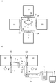
- (A) And (b) is the top view and sectional view which show typically the processing apparatus which comprises a conveyance robot.
- or (d) is a figure explaining the example of abnormality detection by the operation
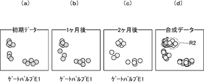
- or (d) is a figure explaining the other example of abnormality detection by the operation
- a transfer robot A is provided in the transfer chamber B.
- the transfer robot A has two motors as drive means (not shown), and a robot arm 2 is connected to the rotation shafts 1a and 1b of the respective concentrically arranged motors via a link mechanism.
- a hand 3 is attached.
- the robot arm 2 can be expanded and contracted and swiveled, and the substrate S can be supported by the robot hand 3 and transferred to a predetermined position.
- the transfer chamber B, the load lock chamber C, and the processing chambers D1 to D3 are connected through gate valves E1 to E4 having driving means 4 such as an air cylinder so that the chambers can be isolated from each other. It has become.
- the transfer chamber B, the load lock chamber C, and the processing chambers D1 to D3 are connected to a vacuum evacuation means P composed of a rotary pump, a cryopump or a turbo molecular pump.
- a cold trap having a well-known structure (not shown) is appropriately provided at a connection point to each of the processing chambers D1 to D3 according to the processing performed in each of the processing chambers D1 to D3.
- the processing chambers D1 to D3 and the like are provided with a vacuum pressure measuring means such as a Pirani gauge or an ion gauge and a gas introducing means for introducing a predetermined gas, although not particularly shown, and according to a predetermined process. Electrodes and a power source for forming discharge plasma are appropriately provided in the processing chambers D1 to D3.
- the control means 5 has a known structure, and includes, for example, a microcomputer. Control (command) contents can be programmed in advance in the microcomputer via a personal computer or the like, and sequence control is performed by sequentially executing the contents. Is.
- the control means 5 is connected to a display means 6 such as a liquid crystal display so that the contents of control can be displayed as appropriate.
- the processing device is provided with a vibration detecting means 7 for detecting a waveform of vibration generated when each movable part is operated.
- a vibration detecting means 7 for detecting a waveform of vibration generated when each movable part is operated.
- an acceleration sensor, a vibration / impact sensor, an AE (acoustic emission) sensor, a microphone horn, or the like having a known structure is used as the vibration detection means 7.
- the vibration detecting means 7 is connected to the control means 5 via a vibration parameter converting means 7a described later, and in order to efficiently detect the vibration waveform generated when each movable part is operated, Attached to the bottom outside.
- a high frequency of 100 kHz such as vibration generated by rubbing the cylinder wall surface when the cold trap is operated from vibration in a low frequency region of 500 Hz or less such as vibration when the motor or gate valves E1 to E4 are operated.
- a combination of a plurality of sensors is used so that vibration can be measured in a wide band up to that of the band (that is, operation monitoring can be performed on all the parts constituting the processing apparatus).
- vibrations in the low frequency band are easy to be transmitted, and even if the movable parts are made of resin, etc., it is difficult to dampen, while vibrations in the high frequency region are damped only by the resin parts, etc.
- the mounting position of each sensor is appropriately selected in order to measure the target vibration.
- the vibration detection means 6 detects the vibration waveform of the currently operating movable part such as the vibration waveform associated with the operation of the gate valves E1 to E4 and the vibration associated with the operation of the vacuum pump P.
- the measured vibration waveform is converted into a characteristic parameter by the vibration parameterization means 7a.
- the case where the vibration of the gate valve E1 is detected by the AE sensor will be described as an example.
- the vibration parameterizing means 7a the duration of the vibration associated with the detected operation of the gate valve E1, the rise and fall times of the vibration The maximum amplitude value, vibration energy and peak frequency are hit processed. That is, a group of waveforms formed by envelope detection of an AE waveform is defined as one signal (hit) and is used as a characteristic parameter (see FIG. 2).
- This characteristic parameter is output to the control means 5 and stored in a storage means such as a memory provided in the control means 5 together with event data that is the control (command) content of the control means 5 such as “gate valve E1 open” (in actual processing)
- event data that is the control (command) content of the control means 5 such as “gate valve E1 open” (in actual processing)
- the vibration waveforms of all the movable parts that are currently operating and vibrate including the movable part are detected, and these are hit processed. Converted into parameters and stored). This makes it easy to synchronize the event data with the characteristic parameters of the vibration waveform, parameterize it, and acquire data (event data and data related to the characteristic parameters) only when one of the movable parts is activated. Together, it eliminates the need to store large amounts of data.
- the obtained characteristic parameters can be displayed on the display means 6.
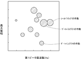
- the first peak value of the vibration waveform is taken on the X axis
- the maximum amplitude of the vibration waveform is taken on the Y axis
- the vibration energy can be displayed as a bubble chart (scatter diagram) representing the size of a circle. Preferred (see FIG. 3).
- the bubble chart is suitable for visualizing the characteristics of waveform data having a large number of characteristic parameters depending on the size of the circle, the color of the circle, the height of the circle, and the like shown on the XY axis.
- the operation of the processing apparatus is stopped and the cause of the vibration is specified. Then, other vibration data based on the cause of occurrence is stored in the storage means, and if other vibration data is detected by the vibration detection means 7 during the operation of any of the movable parts, an abnormality of the processing apparatus is detected. It is configured to determine. As a result, for example, when an AE wave (near 200 kHz) generated when the film attached to the deposition prevention plate provided on the inner walls of the processing chambers D1 to D3 is peeled off, vibration due to a cause that cannot be managed by event data occurs. In addition, it is possible to determine the abnormality of the processing apparatus including the necessity for maintenance.
- AE wave near 200 kHz
- control means 5 performs the same control, that is, “gate valve E1 open” under the same operating environment, for example, when the load lock chamber C and the processing chambers D1 to D3 are maintained at a predetermined degree of vacuum.
- gate valve E1 open the same control as the transfer of the substrate S from one of the processing chambers to another processing chamber is performed (for example, “gate valve E2 open”: the event data substantially match. )
- the vibration detection means 7 detects the vibration waveform generated at that time again, converts it into a characteristic parameter, and compares it with the characteristic parameter of the previous vibration corresponding to the event data.
- the necessity of maintenance due to abnormality or deterioration of the processing apparatus is determined from the deviation of the characteristic parameter with respect to the time axis and the change of the AE energy area.
- abnormal discharge arc discharge
- the transport robot A is transporting. It becomes possible to monitor the removal of the substrate S from the robot hand.
- the vibration detection means 7 A scatter diagram when the waveform is measured and converted into a characteristic parameter is created (see FIG. 5A). And when the said control is selected by the control means 5 in the same environment (when event data are the same), the waveform of a vibration is measured each time, it converts into a characteristic parameter, and creates a scatter diagram, It will be displayed superimposed on the previously created scatter plot.
- the health of the movable part can be easily determined from the change in the waveform of vibration according to the specific event data.
- the vibration waveform changes over time, the deterioration status of the movable part can be known.
- vibration detecting means is not necessary for each of the movable parts, and the cost can be reduced.
- the operation of the gate valve under a certain environment has been described as an example.
- the present invention is not limited to this, and the present invention is not limited to this, as long as it is a movable part that generates vibration in accordance with the operation. Can be applied to manage its operation.
- any form such as a line graph may be used as long as the acquired characteristic parameter can be displayed in an overlapping manner.
- Control means 6 Display means 7 Vibration detection means B Transfer room C Load lock room D1-D3 processing chamber E1 to E4 Gate valve P Vacuum exhaust means S substrate
Landscapes
- Engineering & Computer Science (AREA)
- Human Computer Interaction (AREA)
- Robotics (AREA)
- Mechanical Engineering (AREA)
- Drying Of Semiconductors (AREA)
- Testing Of Devices, Machine Parts, Or Other Structures Thereof (AREA)
- Container, Conveyance, Adherence, Positioning, Of Wafer (AREA)
- Investigating Or Analyzing Materials By The Use Of Ultrasonic Waves (AREA)
- Measurement Of Mechanical Vibrations Or Ultrasonic Waves (AREA)
Abstract
Description
本発明は、処理装置を構成する可動部品が作動するときの振動から当該可動部品の作動を監視できるようにした処理装置の作動監視システムに関する。
従来、基板に成膜処理やエッチング処理などの各種の処理を連続して施す装置として、図1に示すように、搬送ロボットAを配置した中央の搬送室Bを囲うようにして基板Sのロードロック室Cと複数の処理室D1~D3とをゲートバルブE1~E4を介して配置し、搬送ロボットAによりロードロック室Cに投入した基板Sを各処理室Dにまたは各処理室Dの相互間で基板Sを搬送するように構成した処理装置(所謂、クラスタツール装置)が知られている。
このような処理装置においては、搬送ロボットAだけではなく、各処理室Dと搬送室Bとを隔絶する駆動手段を備えたゲートバルブE、冷媒循環式のコールドトラップ(図示せず)や真空ポンプPなど多くの可動部品が設けられ、これらの可動部品によって、基板の搬送を含む、処理対象物に対し所定の処理を施すための処理環境が形成される。その際、上記所定の処理を良好に行うには、常にこれらの可動部品が正常に動作することが必要となる。このことから、個々の可動部品毎に光学式センサなど検知手段を設け、その作動を監視することができるが、これでは装置の構成部品が多くなり、また、管理すべきデータが膨大になって高性能な制御手段が必要となり、結果として、コスト高を招く。
ところで、従来、加速度センサやAEセンサなど装置の振動を検知する振動検知手段を用いて処理装置の異常を検知することが提案されている。例えば、特許文献1には、装置内部や装置外に加速度センサを設置し、この検知手段の出力に基づいて装置を停止させるべき旨の停止信号を出力する停止制御手段を設けることが開示されている。
然し、従来の振動測定による異常検知においては、処理装置の構成部品のうち、異常検知をしようとする測定対象物の異常時における振動の波形を予め取得しておき、それに基づいて異常検知を行っている。このため、測定対象物が特定されているという問題がある。また、予め定めた閾値を超えたときにのみ異常と判断するため、使用頻度に応じて劣化する可動部品の劣化状況などを管理することには不向きである。
そこで、本発明は、以上の点に鑑み、簡単に処理装置を構成する可動部品の経時変化を含む異常を判断することができる低コストの処理装置の作動監視システムを提供することをその課題とする。
上記課題を解決するために、本発明の処理装置の作動監視システムは、処理対象物に対し所定の処理を施す処理室内で所定の処理環境を形成するために設けられている可動部品と、各可動部品の作動を制御する制御手段とを備えた処理装置の作動監視システムであって、前記可動部材の作動に伴い発生する振動の波形を検出する振動検知手段を有し、前記可動部品のいずれかを作動すべく制御手段からの制御が行われた場合、前記制御に応じたイベントデータと、前記振動検知手段により検知され、そのときに作動している全可動部品の振動の波形とを取得し、前記イベントデータに応じた制御が選択される毎に、または前記イベントデータと同種の他のイベントデータに応じた振動の波形が取得されている場合に、前記波形の変化を監視し、当該波形が所定の範囲を超えて変化していると、処理装置の異常を判断するように構成したことを特徴とする。
本発明によれば、制御手段からの制御によりいずれかの可動部品を作動させたとき、その可動部品を含む、作動中の全ての可動部品の作動により発生する振動の波形であって振動が伝わる範囲のものを振動検知手段によりそれぞれ測定し、その制御内容たるイベントデータと共に取得する。そして、例えば、同一の作動環境下で制御手段により同種の制御が行われた(イベントデータが略一致する)とき、振動検知手段により振動の波形を再度それぞれ検知し、そのイベントデータに対応した前回の振動データと比較する。そして、当該振動データのいずれかが所定の範囲を超えて変化していると、処理装置の異常または劣化によるメンテナンスの必要性を判断する。尚、本発明においてイベントデータとは、制御手段からの制御でいずれの可動部品を作動させるとき、制御手段から出力される制御(司令)内容に関するデータであり、「ゲートバルブ開」、「コールドトラップ作動」や「真空ポンプ作動」等の指令データを指す。
上記ように本発明においては、いずれかの可動部品の異常時における振動の波形を予め測定しておくのではなく、可動部品のいずれかが作動する毎に、特定のイベントデータに応じた振動の波形の変化から、簡単に可動部品の健常性が判断される。従って、当該振動の波形が時間を追って変化しているような場合には、可動部品の劣化状況まで監視することが可能になる。また、振動が伝わる範囲で作動している可動部品全ての振動を検知して処理するようにしたため、個々の可動部品毎に振動検知手段は必要ではなく、低コスト化を図ることができる。さらに、処理装置各部の状態を示す情報を一定の周期で取得して処理することで作動監視するような場合と比較して、管理すべきデータの量も少なくでき、クラスターツールのような可動部品が比較的多い処理装置用の作動監視システムとして最適である。
また、本発明においては、前記イベントデータに応じた制御が選択された場合に、前回の振動の波形に含まれない振動の波形が新たに検知された場合、当該振動の発生原因を特定して前記発生原因に基づく他の波形を記憶し、前記可動部品のいずれかの作動中に、前記振動検知手段により前記他の波形が検知されると、処理装置の異常を判断するように構成してもよい。これにより、例えば、成膜室の内壁に設けた防着板に付着した膜が剥離したり、搬送中の基板が破損したり等、イベントデータでは管理できない原因に起因した振動が発生した場合に処理装置の異常を判断できる。
前記取得された振動の波形は所定の特徴パラメータに変換された後、制御手段に設けたメモリや他の公知の記憶装置に記憶されようにしておけば、取得された振動の波形のデータをそのまま保存する場合と比較して、その持続時間、振動の立ち上がり及び立ち下がり時間、最大振幅値、振動エネルギーやピーク周波数等をパラメータに変換して記憶させることで大量のデータを保存しておく必要がなくなり、また、異常の判断も容易となる。
この場合、前記特徴パラメータを表示する表示手段を備えておけば、可動部品の経時変化が可視化でき、その劣化等を分析、判断するのに有利である。
なお、作動中の全ての可動部品の振動を捕らえることができるように、前記振動検知手段は、測定可能な振動の周波数帯域の異なる複数のセンサを組み合わせて構成されたものであることが好ましい。
以下、図1に示す処理装置で本発明を適用した実施の形態について説明する。即ち、搬送室Bには、搬送ロボットAが設けられている。搬送ロボットAは、図示省略した駆動手段たる2個のモータを有し、同心に配置された各モータの回転軸1a、1bにはロボットアーム2がリンク機構をなして連結され、その先端にロボットハンド3が取り付けられている。これにより、各モータの回転軸1a、1bの回転角を適宜制御することで、ロボットアーム2が伸縮及び旋回自在となり、ロボットハンド3で基板Sを支持して所定の位置まで移送可能となる。また、搬送室Bと、ロードロック室C及び処理室D1~D3とは、エアーシリンダ等の駆動手段4を備えたゲートバルブE1~E4を介して連結され、各室が相互に隔絶できるようになっている。
搬送室B、ロードロック室C及び各処理室D1~D3には、ロータリーポンプ、クライオポンプやターボ分子ポンプから構成される真空排気手段Pが接続されている。この場合、各処理室D1~D3で行われる処理に応じて、各処理室D1~D3への接続箇所において図示省略した公知の構造のコールドトラップが適宜設けられる。また、処理室D1~D3等には、特に図示しないが、ピラニ真空計やイオンゲージ等の真空圧測定手段と所定のガスを導入するガス導入手段が設けられ、また、所定の処理に応じて処理室D1~D3内に放電プラズマを形成するための電極や電源が適宜設けられている。
半導体ウエハ等の処理対象物たる基板Sに対し所定の処理を実施するために、例えば当該基板Sのロードロック室Cから各処理室D1~D3への移送や真空(プラズマ)雰囲気の形成等の所定の処理環境を形成すべく搬送室B、ロードロック室C及び各処理室Dに適宜装備された上記各部品が、本実施の形態の可動部品を構成する。これらの可動部品の作動は、制御手段5により制御される。制御手段5は、公知の構造を有するものであり、例えばマイクロコンピュータを備え、このマイクロコンピュータにパソコン等を介して制御(指令)内容を予めプログラムでき、これを逐次実行することによりシーケンス制御を行うものである。また、制御手段5には、液晶ディスプレイ等などの表示手段6が連結され、制御内容を適宜表示できるようになっている。
処理装置には、各可動部品が作動したとき、それに伴って発生する振動の波形を検知するため振動検知手段7が設けられている。振動検知手段7としては、公知の構造を有する加速度センサ、振動/衝撃センサ、AE(アコースティックエミッション)センサやマイクホーン等が用いられる。振動検知手段7は、後述する振動パラメータ変換手段7aを介して制御手段5に接続され、また、各可動部品が作動したときに発生した振動の波形を効率よく検知するため、例えば搬送室Bの底面外側に取り付けられる。
ここで、モータやゲートバルブE1~E4の作動時の振動のような500Hz以下の低周波領域の振動から、上記コールドトラップ作動時にピストンがシリンダ壁面を擦れることで発生する振動のような100kHzの高周波帯域のものまで広帯域で振動測定が可能となるように(即ち、処理装置を構成する全部品に対し作動監視が可能となるように)、上記センサを複数組み合わせて使用される。
尚、低周波帯域の振動は伝わり易く、可動部品が樹脂製等であっても減衰し難い一方で、高周波領域の振動は樹脂製部品等が介在するだけで減衰するため、これらの振動の特性を考慮し、目的とする振動を測定するために上記各センサの取付位置は適宜選択される。
次に、本実施の形態に係る処理装置の作動監視について、例えば、真空排気手段の作動により搬送室B、ロードロック室C及び各処理室D1~D3が所定の真空度に保持された状態でロードロック室Cに設置された基板Sをいずれかの処理室D1~D3に移送する場合を例に説明する。先ず、制御手段5からの制御により、ロードロック室Cが所定の真空度に達していることを確認した後、搬送室Bと、ロードロック室C及び処理室D1~D3との間にある2個のゲートバルブE1~E4を開ける。このとき、振動検知手段6によって、ゲートバルブE1~E4の作動に伴う振動の波形や真空ポンプPの作動に伴う振動など現在作動している可動部品の振動の波形が検知される。
測定された振動の波形は、振動パラメータ化手段7aにより特徴パラメータにそれぞれ変換される。AEセンサによりゲートバルブE1の振動を検知した場合を例に説明すると、振動パラメータ化手段7aにおいては、検知されたゲートバルブE1の作動に伴う振動の波形の持続時間、振動の立ち上がり及び立ち下がり時間、最大振幅値、振動エネルギーやピーク周波数がヒット処理される。つまり、AE波形を包絡線検波してできる波形のひとかたまりを一個の信号(ヒット)と定義し、特徴パラメータとされる(図2参照)。
この特徴パラメータは制御手段5に出力され、「ゲートバルブE1開」という制御手段5による制御(指令)内容たるイベントデータと共に制御手段5に設けたメモリ等の記憶手段に記憶させる(実際の処理においては、制御手段5からの制御によりいずれかの可動部品が作動した場合、その可動部品を含む現在作動中で振動している全可動部品の振動の波形が検知され、これらがヒット処理されて特徴パラメータにそれぞれ変換されて記憶される)。これにより、イベントデータと振動波形の特徴パラメータとの同期が容易となり、また、パラメータ化することと、いずれか可動部品が作動するときだけデータ(イベントデータ及び特徴パラメータに関するデータ)を取得することとが相俟って、大量のデータを保存する必要を無くすことができる。
また、得られた特徴パラメータは、表示手段6に表示させることができる。この場合、例えば、X軸に振動波形の第1のピーク値、Y軸に振動波形の最大振幅を取り、振動エネルギーを円の大きさで表すようなバブルチャート(散布図)として表示することが好ましい(図3参照)。これにより、イベントデータに応じた各可動部品の振動が可視化できる。尚、バブルチャートは、X-Y軸上に示す円の大きさ、円の色、円の高さ等により多数の特徴パラメータを持つ波形データの特徴を可視化するのに適している。
ここで、得られた特徴パラメータを一定の期間に亘って蓄積していくと、通常発生する振動はバブルチャート上で特定の領域に集まってくる。このため、図4に示すように、特徴パラメータを蓄積し、その発生回数を含めて表示手段6に表示させていくと、可動部品の作動以外で他の振動が発生した場合、上記領域以外の領域に振動の発生が表われることで直ちに見分けることができるようになる(イベントデータとそれに応じた特徴パラメータとのデータを消去すれば、より顕著に現わすことができる)。
このような場合には、例えば処理装置の作動を停止し、当該振動の発生原因を特定する。そして、当該発生原因に基づく他の振動データを記憶手段に記憶させておき、前記可動部品のいずれかの作動中に、振動検知手段7により他の振動データが検知されると、処理装置の異常を判断するように構成しておく。これにより、例えば、処理室D1~D3内壁に設けた防着板に付着した膜が剥離した場合に発生するAE波(200kHz付近)等、イベントデータでは管理できない原因に起因した振動が発生した場合に、メンテナンスの必要性を含む処理装置の異常を判断できるようになる。
次いで、例えば、ロードロック室C及び各処理室D1~D3が所定の真空度に保持された状態等、同一の作動環境下で制御手段5により同一の制御、つまり、「ゲートバルブE1開」という指令がなされたとき、または、いずれかの処理室から他の処理室への基板Sの移送のような同種の制御が行われた(例えば、「ゲートバルブE2開」:イベントデータが略一致する)場合、振動検知手段7でそのときに発生している振動の波形を再度それぞれ検知して特徴パラメータに変換し、そのイベントデータに対応した前回の振動の特徴パラメータと比較する。そして、特徴パラメータの時間軸に対するずれやAEエネルギー面積の変化から処理装置の異常または劣化によるメンテナンスの必要性を判断する。これにより、モータ、ゲートバルブやコールドトラップの作動の監視だけでなく、例えば、処理室内でプラズマ処理を実施している場合における異常放電(アーク放電)の発生、または、搬送ロボットAによる搬送中でのロボットハンドからの基板Sの脱落等まで、監視できるようになる。
次に、本実施の形態において処理装置の作動監視により可動部品の異常を検知した例を説明する。制御手段5により搬送室B、ロードロック室C及び各処理室D1~D3が所定の真空度に保持された状態でゲートバルブE1~E3をそれぞれ作動させた場合(イベントデータが同種である場合)に、振動検知手段7により振動の波形を測定し、特徴パラメータに変換し、それに応じてそれぞれの散布図を作成する(図4(a)乃至図4(c)参照)。そして、これらの散布図を重ね合わせることで(図4(d)参照)、ゲートバルブE2を作動させたときのみ、振動検知手段7により異常な振動(符号R1で示す領域)が検知されることが判る。これにより、ゲートバルブE2に異常が発生していることが判る。このような場合には、ゲートバルブE2自体を交換する。
他方で、制御手段5により搬送室B、ロードロック室C及び各処理室D1~D3が所定の真空度に保持された状態でゲートバルブE1を作動させた場合に、振動検知手段7により振動の波形を測定し、特徴パラメータに変換したときの散布図を作成する(図5(a)参照)。そして、同一の環境下で制御手段5により上記制御が選択された場合(イベントデータが同一である場合)、その都度、振動の波形を測定し、特徴パラメータに変換して散布図を作成し、前回作成した散布図と重ね合わせて表示させていく。
このように各散布図を重ね合わせることで(図5(d)参照)、ゲートバルブE1の使用時間が長くなると、振動検知手段7により測定される振動が変化していることが判る(図5では、符号R2で示す領域が右側にシフトしている)。これにより、ゲートバルブE1に異常が発生または発生する可能性があることが判る。このような場合には、ゲートバルブE1自体を交換する。
以上説明したように本発明の実施の形態では、可動部品のいずれかが作動する毎に、特定のイベントデータに応じた振動の波形の変化から、簡単に可動部品の健常性が判断でき、特に、当該振動の波形が時間を追って変化しているような場合には、可動部品の劣化状況を知ることができる。また、振動が伝わる範囲であれば、作動している可動部品全ての振動を検知して処理するため、個々の可動部品毎に振動検知手段は必要ではなく、低コスト化を図ることができる。
なお、本実施の形態では、一定の環境下でのゲートバルブの作動を例に説明したが、これに限定されるものではなく、作動に伴って振動を発生する可動部品であれば、本発明を適用してその作動を管理することができる。また、振動の波形を特徴パラメータに変化し、バルブチャートにより表示するものを例に説明したが、取得した特徴パラメータを重ね合わせて表示できるものであれば、折れ線グラフ等、その形態は問わない。
5 制御手段
6 表示手段
7 振動検知手段
B 搬送室
C ロードロック室
D1~D3 処理室
E1~E4 ゲートバルブ
P 真空排気手段
S 基板
Claims (5)
-
処理対象物に対し所定の処理を施す処理室内で所定の処理環境を形成するために設けられている可動部品と、各可動部品の作動を制御する制御手段とを備えた処理装置の作動監視システムであって、
前記可動部材の作動に伴い発生する振動の波形を検出する振動検知手段を有し、
前記可動部品のいずれかを作動すべく制御手段からの制御が行われた場合、前記制御に応じたイベントデータと、前記振動検知手段により検知され、そのときに作動している全可動部品の振動の波形とを取得し、
前記イベントデータに応じた制御が選択される毎に、または前記イベントデータと同種の他のイベントデータに応じた振動の波形が取得されている場合に、前記波形の変化を監視し、当該波形が所定の範囲を超えて変化していると、処理装置の異常を判断するように構成したことを特徴とする処理装置の作動監視システム。
-
前記イベントデータに応じた制御が選択された場合に、前回の振動の波形に含まれない振動の波形が新たに検知された場合、当該振動の発生原因を特定して前記発生原因に基づく他の波形を記憶し、
前記可動部品のいずれかの作動中に、前記振動検知手段により前記他の波形が検知されると、処理装置の異常を判断するように構成したことを特徴とする請求項1記載の処理装置の作動監視システム。
-
前記取得された振動の波形は所定の特徴パラメータに変換された後、記憶されることを特徴とする請求項1または請求項2記載の処理装置の作動監視システム。
-
前記特徴パラメータを表示する表示手段を備えたことを特徴とする請求項3記載の処理装置の作動監視システム。
-
前記振動検知手段は、測定可能な振動の周波数帯域の異なる複数のセンサを組み合わせて構成されていることを特徴とする請求項1乃至請求項4のいずれか1項に記載の処理装置の作動監視システム。
Priority Applications (4)
| Application Number | Priority Date | Filing Date | Title |
|---|---|---|---|
| US13/054,107 US8688246B2 (en) | 2008-07-24 | 2009-07-21 | Operation monitoring system for processing apparatus |
| JP2010521599A JP5373793B2 (ja) | 2008-07-24 | 2009-07-21 | 処理装置の作動監視システム |
| DE112009001777T DE112009001777T5 (de) | 2008-07-24 | 2009-07-21 | Betriebsüberwachungssystem für Bearbeitungsvorrichtung |
| CN200980128998.0A CN102105975B (zh) | 2008-07-24 | 2009-07-21 | 处理装置的动作监视系统 |
Applications Claiming Priority (2)
| Application Number | Priority Date | Filing Date | Title |
|---|---|---|---|
| JP2008190629 | 2008-07-24 | ||
| JP2008-190629 | 2008-07-24 |
Publications (1)
| Publication Number | Publication Date |
|---|---|
| WO2010010688A1 true WO2010010688A1 (ja) | 2010-01-28 |
Family
ID=41570158
Family Applications (1)
| Application Number | Title | Priority Date | Filing Date |
|---|---|---|---|
| PCT/JP2009/003413 Ceased WO2010010688A1 (ja) | 2008-07-24 | 2009-07-21 | 処理装置の作動監視システム |
Country Status (7)
| Country | Link |
|---|---|
| US (1) | US8688246B2 (ja) |
| JP (1) | JP5373793B2 (ja) |
| KR (1) | KR101585620B1 (ja) |
| CN (1) | CN102105975B (ja) |
| DE (1) | DE112009001777T5 (ja) |
| TW (1) | TWI484582B (ja) |
| WO (1) | WO2010010688A1 (ja) |
Cited By (6)
| Publication number | Priority date | Publication date | Assignee | Title |
|---|---|---|---|---|
| JP2015078884A (ja) * | 2013-10-16 | 2015-04-23 | 富士通株式会社 | 監視装置、監視プログラムおよび監視方法 |
| US9595667B2 (en) | 2012-08-31 | 2017-03-14 | Micron Technology, Inc. | Three dimensional memory array architecture |
| WO2018159160A1 (ja) * | 2017-03-03 | 2018-09-07 | 株式会社デンソー | 診断システム |
| JP2018146562A (ja) * | 2017-03-03 | 2018-09-20 | 株式会社デンソー | 診断システム |
| JP2019203815A (ja) * | 2018-05-24 | 2019-11-28 | 矢崎エナジーシステム株式会社 | ガスメータ |
| JP2024031303A (ja) * | 2022-08-26 | 2024-03-07 | 株式会社アルバック | 情報処理装置、情報処理方法およびプログラム |
Families Citing this family (9)
| Publication number | Priority date | Publication date | Assignee | Title |
|---|---|---|---|---|
| KR101884742B1 (ko) * | 2011-10-13 | 2018-08-30 | 세메스 주식회사 | 웨이퍼 이송 방법 |
| JP6044373B2 (ja) * | 2013-02-04 | 2016-12-14 | 東京エレクトロン株式会社 | 基板搬送装置 |
| US10871477B2 (en) * | 2015-08-20 | 2020-12-22 | The United States Of America, As Represented By The Secretary Of The Navy | Contaminant cleaning systems and related methods using one or more reactive substances, reaction byproduct measurements, and differential pressure or vacuum transfer of the reactive substances and reaction byproducts |
| KR101863781B1 (ko) * | 2016-09-08 | 2018-06-01 | 두산중공업 주식회사 | 로터 진동 이상 감지 장치 및 방법 |
| CN109314074B (zh) * | 2016-09-29 | 2023-07-04 | 株式会社国际电气 | 基板处理装置、振动检测系统以及计算机可读取记录介质 |
| KR101883885B1 (ko) * | 2017-11-05 | 2018-08-30 | 조대복 | 로봇진단시스템 및 로봇진단방법 |
| CN110539331A (zh) * | 2018-05-28 | 2019-12-06 | 睿胜自动化工程有限公司 | 可预先侦测机械手臂及泵异常的方法及装置 |
| JP2020165902A (ja) * | 2019-03-29 | 2020-10-08 | 新東工業株式会社 | 検査装置 |
| KR20220138953A (ko) * | 2021-04-07 | 2022-10-14 | 세메스 주식회사 | 기판 처리 장치 |
Citations (3)
| Publication number | Priority date | Publication date | Assignee | Title |
|---|---|---|---|---|
| JPH06320457A (ja) * | 1993-05-13 | 1994-11-22 | Fujitsu Ltd | 知能ロボットシステム |
| JP2002076032A (ja) * | 2000-08-29 | 2002-03-15 | Nec Machinery Corp | 半導体製造装置 |
| JP2006278396A (ja) * | 2005-03-28 | 2006-10-12 | Tokyo Electron Ltd | 処理装置及びプログラム |
Family Cites Families (10)
| Publication number | Priority date | Publication date | Assignee | Title |
|---|---|---|---|---|
| JPS6018729A (ja) * | 1983-07-11 | 1985-01-30 | Mitsubishi Electric Corp | 振動監視装置 |
| JPS6021423A (ja) * | 1983-07-15 | 1985-02-02 | Mitsubishi Electric Corp | 振動監視装置 |
| US5206816A (en) * | 1991-01-30 | 1993-04-27 | Westinghouse Electric Corp. | System and method for monitoring synchronous blade vibration |
| US5847658A (en) * | 1995-08-15 | 1998-12-08 | Omron Corporation | Vibration monitor and monitoring method |
| JPH09237757A (ja) * | 1996-02-29 | 1997-09-09 | Canon Inc | 半導体製造装置 |
| JP4261041B2 (ja) * | 2000-09-18 | 2009-04-30 | 株式会社東芝 | 高電圧機器の絶縁異常診断装置及びその絶縁異常診断方法 |
| JP2002209299A (ja) * | 2000-12-28 | 2002-07-26 | Toshiba Corp | 半導体振動センサ |
| US6937941B2 (en) * | 2003-11-20 | 2005-08-30 | Bently Nevada, Llc | Impulse monitoring system: apparatus and method |
| US20060215347A1 (en) | 2005-03-28 | 2006-09-28 | Tokyo Electron Limited | Processing apparatus and recording medium |
| US7702401B2 (en) * | 2007-09-05 | 2010-04-20 | Fisher-Rosemount Systems, Inc. | System for preserving and displaying process control data associated with an abnormal situation |
-
2009
- 2009-07-21 WO PCT/JP2009/003413 patent/WO2010010688A1/ja not_active Ceased
- 2009-07-21 DE DE112009001777T patent/DE112009001777T5/de not_active Ceased
- 2009-07-21 JP JP2010521599A patent/JP5373793B2/ja active Active
- 2009-07-21 CN CN200980128998.0A patent/CN102105975B/zh active Active
- 2009-07-21 KR KR1020117004291A patent/KR101585620B1/ko active Active
- 2009-07-21 US US13/054,107 patent/US8688246B2/en active Active
- 2009-07-23 TW TW098124874A patent/TWI484582B/zh active
Patent Citations (3)
| Publication number | Priority date | Publication date | Assignee | Title |
|---|---|---|---|---|
| JPH06320457A (ja) * | 1993-05-13 | 1994-11-22 | Fujitsu Ltd | 知能ロボットシステム |
| JP2002076032A (ja) * | 2000-08-29 | 2002-03-15 | Nec Machinery Corp | 半導体製造装置 |
| JP2006278396A (ja) * | 2005-03-28 | 2006-10-12 | Tokyo Electron Ltd | 処理装置及びプログラム |
Cited By (8)
| Publication number | Priority date | Publication date | Assignee | Title |
|---|---|---|---|---|
| US9595667B2 (en) | 2012-08-31 | 2017-03-14 | Micron Technology, Inc. | Three dimensional memory array architecture |
| JP2015078884A (ja) * | 2013-10-16 | 2015-04-23 | 富士通株式会社 | 監視装置、監視プログラムおよび監視方法 |
| WO2018159160A1 (ja) * | 2017-03-03 | 2018-09-07 | 株式会社デンソー | 診断システム |
| JP2018146562A (ja) * | 2017-03-03 | 2018-09-20 | 株式会社デンソー | 診断システム |
| JP2019203815A (ja) * | 2018-05-24 | 2019-11-28 | 矢崎エナジーシステム株式会社 | ガスメータ |
| JP7055701B2 (ja) | 2018-05-24 | 2022-04-18 | 矢崎エナジーシステム株式会社 | ガスメータ |
| JP2024031303A (ja) * | 2022-08-26 | 2024-03-07 | 株式会社アルバック | 情報処理装置、情報処理方法およびプログラム |
| JP7575432B2 (ja) | 2022-08-26 | 2024-10-29 | 株式会社アルバック | 情報処理装置、情報処理方法およびプログラム |
Also Published As
| Publication number | Publication date |
|---|---|
| JPWO2010010688A1 (ja) | 2012-01-05 |
| US20110125331A1 (en) | 2011-05-26 |
| CN102105975A (zh) | 2011-06-22 |
| US8688246B2 (en) | 2014-04-01 |
| TWI484582B (zh) | 2015-05-11 |
| JP5373793B2 (ja) | 2013-12-18 |
| KR101585620B1 (ko) | 2016-01-14 |
| TW201009992A (en) | 2010-03-01 |
| CN102105975B (zh) | 2013-09-11 |
| KR20110040955A (ko) | 2011-04-20 |
| DE112009001777T5 (de) | 2011-05-26 |
Similar Documents
| Publication | Publication Date | Title |
|---|---|---|
| JP5373793B2 (ja) | 処理装置の作動監視システム | |
| US8120376B2 (en) | Fault detection apparatuses and methods for fault detection of semiconductor processing tools | |
| US9245710B2 (en) | Charged particle beam device | |
| JP2017142153A (ja) | 寿命予測方法、寿命予測装置、および寿命予測システム | |
| JP2008072030A (ja) | プラズマ処理装置、プラズマ処理装置の異常検出方法、及びプラズマ処理方法 | |
| US20250369818A1 (en) | Fault detection system for vacuum pump | |
| JP2018077764A (ja) | 異常検知装置 | |
| JP2016134585A (ja) | 半導体製造装置、半導体製造装置の診断システムおよび半導体装置の製造方法 | |
| KR20230041566A (ko) | 기판 처리 방법, 기판 처리 장치, 반도체 처리 장치의 제조 방법 및 프로그램 | |
| JP2009287573A (ja) | ターボ分子ポンプおよびその故障予測方法 | |
| JPH11214489A (ja) | 真空処理装置 | |
| KR20080071814A (ko) | 음원 노이즈를 이용한 설비의 동작이상 감지장치 및 그감지장치를 포함한 반도체 제조 설비 | |
| US20040149208A1 (en) | Particle control device and particle control method for vacuum processing apparatus | |
| CN114167842B (zh) | 一种基于振动主动控制系统的故障预测与健康管理方法 | |
| EP2009287B1 (en) | Vacuum-exhaust device and vacuum-exhaust method | |
| JP4417318B2 (ja) | 設備診断装置 | |
| JP2018146562A (ja) | 診断システム | |
| JP7309079B2 (ja) | 設備状態監視装置、異常判定システムおよび設備状態監視方法 | |
| WO2015029777A1 (ja) | プラズマ処理装置及びプラズマ処理装置の監視方法 | |
| JP2006509950A (ja) | 往復圧縮機を監視する方法及びシステム | |
| JP2006221308A (ja) | 異常検出方法および制御装置と、これらを用いた制御システム | |
| GB2591100A (en) | Vacuum pump monitoring method and apparatus | |
| KR100203403B1 (ko) | 벨트 전동 방식 반도체 제조 장치 | |
| JP3304430B2 (ja) | ガス供給監視装置及び方法 | |
| JP2004177213A (ja) | 異常対応型ヘリウムリークディテクタ |
Legal Events
| Date | Code | Title | Description |
|---|---|---|---|
| WWE | Wipo information: entry into national phase |
Ref document number: 200980128998.0 Country of ref document: CN |
|
| 121 | Ep: the epo has been informed by wipo that ep was designated in this application |
Ref document number: 09800204 Country of ref document: EP Kind code of ref document: A1 |
|
| WWE | Wipo information: entry into national phase |
Ref document number: 2010521599 Country of ref document: JP |
|
| WWE | Wipo information: entry into national phase |
Ref document number: 13054107 Country of ref document: US |
|
| ENP | Entry into the national phase |
Ref document number: 20117004291 Country of ref document: KR Kind code of ref document: A |
|
| RET | De translation (de og part 6b) |
Ref document number: 112009001777 Country of ref document: DE Date of ref document: 20110526 Kind code of ref document: P |
|
| 122 | Ep: pct application non-entry in european phase |
Ref document number: 09800204 Country of ref document: EP Kind code of ref document: A1 |