WO2010010607A1 - 散乱線除去グリッドの製造方法 - Google Patents
散乱線除去グリッドの製造方法 Download PDFInfo
- Publication number
- WO2010010607A1 WO2010010607A1 PCT/JP2008/063127 JP2008063127W WO2010010607A1 WO 2010010607 A1 WO2010010607 A1 WO 2010010607A1 JP 2008063127 W JP2008063127 W JP 2008063127W WO 2010010607 A1 WO2010010607 A1 WO 2010010607A1
- Authority
- WO
- WIPO (PCT)
- Prior art keywords
- metal foil
- ray
- tension
- guide slit
- metal foils
- Prior art date
- Legal status (The legal status is an assumption and is not a legal conclusion. Google has not performed a legal analysis and makes no representation as to the accuracy of the status listed.)
- Ceased
Links
Images



Classifications
-
- G—PHYSICS
- G21—NUCLEAR PHYSICS; NUCLEAR ENGINEERING
- G21K—HANDLING OF PARTICLES OR IONISING RADIATION NOT OTHERWISE PROVIDED FOR; IRRADIATION DEVICES; GAMMA RAY OR X-RAY MICROSCOPES
- G21K1/00—Arrangements for handling particles or ionising radiation, e.g. focusing or moderating
- G21K1/02—Arrangements for handling particles or ionising radiation, e.g. focusing or moderating using diaphragms, collimators
- G21K1/025—Arrangements for handling particles or ionising radiation, e.g. focusing or moderating using diaphragms, collimators using multiple collimators, e.g. Bucky screens; other devices for eliminating undesired or dispersed radiation
-
- Y—GENERAL TAGGING OF NEW TECHNOLOGICAL DEVELOPMENTS; GENERAL TAGGING OF CROSS-SECTIONAL TECHNOLOGIES SPANNING OVER SEVERAL SECTIONS OF THE IPC; TECHNICAL SUBJECTS COVERED BY FORMER USPC CROSS-REFERENCE ART COLLECTIONS [XRACs] AND DIGESTS
- Y10—TECHNICAL SUBJECTS COVERED BY FORMER USPC
- Y10T—TECHNICAL SUBJECTS COVERED BY FORMER US CLASSIFICATION
- Y10T29/00—Metal working
- Y10T29/49—Method of mechanical manufacture
- Y10T29/49002—Electrical device making
-
- Y—GENERAL TAGGING OF NEW TECHNOLOGICAL DEVELOPMENTS; GENERAL TAGGING OF CROSS-SECTIONAL TECHNOLOGIES SPANNING OVER SEVERAL SECTIONS OF THE IPC; TECHNICAL SUBJECTS COVERED BY FORMER USPC CROSS-REFERENCE ART COLLECTIONS [XRACs] AND DIGESTS
- Y10—TECHNICAL SUBJECTS COVERED BY FORMER USPC
- Y10T—TECHNICAL SUBJECTS COVERED BY FORMER US CLASSIFICATION
- Y10T29/00—Metal working
- Y10T29/49—Method of mechanical manufacture
- Y10T29/49002—Electrical device making
- Y10T29/49016—Antenna or wave energy "plumbing" making
-
- Y—GENERAL TAGGING OF NEW TECHNOLOGICAL DEVELOPMENTS; GENERAL TAGGING OF CROSS-SECTIONAL TECHNOLOGIES SPANNING OVER SEVERAL SECTIONS OF THE IPC; TECHNICAL SUBJECTS COVERED BY FORMER USPC CROSS-REFERENCE ART COLLECTIONS [XRACs] AND DIGESTS
- Y10—TECHNICAL SUBJECTS COVERED BY FORMER USPC
- Y10T—TECHNICAL SUBJECTS COVERED BY FORMER US CLASSIFICATION
- Y10T29/00—Metal working
- Y10T29/49—Method of mechanical manufacture
- Y10T29/49826—Assembling or joining
Definitions
- the present invention relates to a method for manufacturing a scattered X-ray removal grid, and more particularly to a method for manufacturing a scattered X-ray removal grid using air as an intermediate substance.
- an object and an X-ray detector are used for the purpose of preventing X-rays scattered by the object from entering the X-ray detector.
- a scattered X-ray removal grid is disposed between the two.
- This type of grid is composed of a large number of foil-shaped X-ray absorbing materials made of lead and the like, and an intermediate material as a spacer interposed between the foil-shaped X-ray absorbing materials. Arranged so as to be parallel to the primary X-ray.
- the foil-like X-ray absorbing material is arranged so that the extension of each surface is focused on one straight line at the focusing distance A so-called focusing grid is used.
- a parallel grid in which the respective foil-shaped X-ray absorbing materials are arranged in parallel to each other may be used for special purposes.
- a plurality of pins are arranged at intervals substantially parallel to each other on opposite portions of the frame forming the outer frame of the grid, and a tape as an X-ray absorbing material is applied to each pin.
- the tape as the X-ray absorbing material is a tape made of polyethylene terephthalate resin coated with tungsten powder.
- a large number of metal foils as X-ray absorbing materials provided therebetween are fitted in parallel with each other at a predetermined distance so as to be parallel to the primary X-rays.
- a guide slit plate formed with a large number of guide slits is relatively fixed and arranged, and both ends of the metal foil are inserted into the guide slits facing each other of the guide slit plates.
- a scattered X-ray removal grid in which one end or both ends of each metal foil is held in a state in which tension is applied by an urging means outside the slit has already been considered.
- an elastic tube for example, silicon tube
- the size of the hole diameter of each metal foil is limited, but the fixed rod also needs to be as large as possible in order to maintain rigidity, and as a result, the elastic tube
- the outer diameter and inner diameter of the elastic tube are limited to a minimum, and the thickness of the cross section of the elastic tube is very thin, that is, the spring constant k determined when the elastic tube is compressed is large. Therefore, when there is variation in the hole interval of each metal foil, the elastic tube compression amount x is large when the hole interval of the metal foil is short, and small when the hole interval of the metal foil is long. Become.
- metal foils as X-ray absorbing materials are usually as thin as several tens of ⁇ m.
- tungsten, tungsten alloy, molybdenum or the like is selected as the material, the strength is relatively high and rods are used. Even if the metal foil is inserted into a hole and pulled, the hole of the metal foil has a high limit point for deformation, and there is no problem.
- a material with relatively low strength such as lead, lead alloy, copper, copper alloy, iron, iron alloy, nickel, etc.
- the metal foil hole When inserted into a metal foil hole and pulled, the metal foil hole has a low limit of deformation, and a metal foil with a short hole interval will be subjected to a particularly large tension, and the hole will deform and cannot be pulled well. In the worst case, disconnection can occur.
- the present invention has been made in view of such circumstances, and it is possible to stably produce a scattered X-ray removing grid that can use air as an intermediate substance and can accurately position and hold a metal foil as an X-ray absorbing substance at low cost. Therefore, it is an object to provide a method that can be manufactured.
- the method for producing a scattered X-ray removal grid includes a large number of metal foils as X-ray absorbing materials provided between them in parallel with each other at a predetermined distance.
- a guide slit plate formed with a large number of guide slits to be fitted so as to be parallel to the primary X-rays is relatively fixed and arranged, and the guide slit plates facing each other are arranged.
- each metal foil is inserted with a rod covered with a resilient elastic body into the hole formed further on the tip side than the insertion part with both end portions inserted in the guide slit.
- the cross-sectional shape of the elastic body that is held and pulled and covers the rod has a structure that ensures a sufficient thickness with respect to the direction in which the elastic body is compressed when tension is generated.
- the determined spring constant k is made small so that the difference in tension is eliminated even if there is a difference in the compression amount (Claim 1).
- the slits are inserted in the guide slits of the guide slit plates fixed in parallel with each other at both ends of a large number of metal foils as X-ray absorbing materials.
- the primary X-ray incident side and the outgoing side of the metal foil in a state where the tension is uniformly applied to one end or both ends of each metal foil by the biasing means and the shape of each metal foil is corrected outside Adhere as a grid cover so as to cover each thin plate made of light elements (such as carbon fiber sheet and aluminum sheet), and cut the both ends of the metal foil inside the guide slit plate in that state, and the grid cover adheres Since a grid with air as an intermediate material is realized by taking out the metal foil that has been removed, the primary material is more efficient than when aluminum or fiber is used as the intermediate material. Improved transmittance of lines, which makes it possible to reduce the exposure amount of the subject.
- a thin metal foil material as an X-ray absorbing substance, lead, lead alloy, copper, copper alloy, iron, iron alloy, nickel, etc. Even when materials with relatively low strength or similar strength are selected, the holes in the metal foil are deformed because the rod can be inserted into each metal foil hole and pulled uniformly. Therefore, the positioning and shape correction of the metal foil can be reliably performed, and the scattered X-ray removal grid using air as an intermediate substance can be manufactured stably and inexpensively.
- FIG. 1 is a perspective view showing a manufacturing process of a scattered X-ray removal grid
- FIG. 2 is a side view thereof.
- Support members 23 and 24 are respectively fixed to the upper surfaces of the other two sides orthogonal to the opposite two sides of the rectangular frame 1 having the hollow space 2. Both end portions of one guide slit plate 21 of the guide slit mechanism 20 are fixed to the end portions of the support members 23 and 24, and the other guide slit plate 22 is overlapped with the guide slit plate 21 in the plate thickness direction. It is fixed in the state.
- the guide slit plate 22 is screwed to the guide slit plate 21, and the screwing through hole has a required gap with respect to the screw, and the guide slit plate 22 guides within the gap. The position relative to the slit plate 21 can be changed in the width direction of the guide slit 20a.
- the guide slit mechanism 20 includes two guide slit plates 21 and 22 each having the same number of guide slits 20a formed at the same pitch, and the width of the guide slit 20a of each of the guide slit plates 21 and 22 is the metal foil 3. It is considerably wider than the thickness. Of these guide slit plates 21 and 22, one guide slit plate 21 is fixed to the frame 1, and the other guide slit plate 22 is fixed to the guide slit plate 21.
- the positions of the guide slit plates 21 and 22 in both the guide slit mechanisms 20 are substantially matched.
- the guide slit plate 22 is moved in the width direction of the guide slit 20a, and the metal foil 3 is sandwiched between the guide slit plates 21 and 22 without any gap. Is fixed to the guide slit plate 21. Thereby, each metal foil 3 is guided to the guide slit mechanism 20 in the state in which the both ends have no gap.
- the guide slit 20a is arranged so that the metal foil 3 inserted therebetween is parallel to the X-rays irradiated from the X-ray focal point F under a preset focal length (for example, 120 cm), and Are formed with an interval, a posture, and a length such that a set grid ratio (for example, 10) is obtained.
- the width of each guide slit 20a is precisely machined by, for example, CN electric discharge machining.
- Each metal foil 3 is inserted in the guide slit 20a of the guide slit mechanism 20 in the vicinity of both end portions thereof, and the fixed rod 4 and the tension rod 4 are respectively inserted into the holes 25 formed on the distal end side of the insertion portion. 5 is held by being inserted.
- the material of the metal foil 3 is not particularly limited as long as it has a required X-ray absorption coefficient. In this example, a molybdenum foil is used.
- one fixed rod 4 is fixed to the frame body 1 via a fixing bracket 11.
- a plurality of fixing brackets 11 are arranged every several metal foils 3 so that the fixing rod 4 is fixed without being bent during pulling, and the holes of the fixing bracket 11 are arranged.
- the fixed rod 4 is supported by passing through.
- the other tension rod 5 is not fixed to the frame 1.
- One end of a plurality of tension coil springs 7 is engaged with the tension rod 5, and the other end of the plurality of tension coil springs 7 is engaged with a support rod 9 fixed in parallel with the tension rod 5.
- a plurality of tension coil springs 7 are engaged with the tension rods 5 every several metal foils 3 so that the tension rods 5 are pulled without being bent while being pulled.
- a plurality of fixing brackets 12 are arranged between the coil springs 7 so that the support rod 9 is fixed without being bent and remains straight. The support rod 9 is supported by passing through.
- the fixing bracket 12 is fixedly arranged on the moving base 13, and the metal foil 3 is pulled by the sliding movement of the moving base 13 on the frame 1, thereby applying tension to each metal foil 3. Is done.
- the interval between the holes 25 of each metal foil 3 inserted and pulled into each guide slit 20a varies due to a hole diameter processing error, a hole interval processing error, an error due to deformation of the hole due to tension, an arrangement error, and the like. Has occurred. Even in such a state, the tension rod 5 is elastic with respect to the metal core bar 6 in order to absorb the error in the tension rod 5 in order to uniformly apply tension to each metal foil 3. It is necessary to make it the structure covered with a certain elastic tube 10, and the detail of the cross-sectional shape is shown in FIG.
- the cross-sectional shape of the elastic tube 10 covering the metal core 6 in the tension rod 5 is such that when the tensile force FF is generated, the elastic tube 10 is connected to the metal core 6 and the metal foil 3. A sufficient thickness is secured with respect to the thickness d in the direction compressed between the two.
- the outer shape of the elastic tube 10 is an ellipse
- the inner shape is a perfect circle arranged slightly eccentric to one side.
- the shape of the hole 25 of each metal foil 3 is also an ellipse.
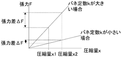
- the spring constant k of the wall thickness d portion of the elastic tube 10 determined when compression is performed, the spring constant k is small when the wall thickness d is large, and is large when the wall thickness d is small.
- the outer diameter and the inner diameter of the elastic tube are limited to the minimum as in the conventionally proposed biasing means, and the spring constant k is large and the tension difference ⁇ F when the wall thickness of the elastic tube is very thin.
- the spring constant k is small and the tension difference ⁇ F is small when the thickness d of the elastic tube 10 is sufficient as in the case of the present embodiment.
- 8a and 8b are bonded to a grid cover made of, for example, a carbon fiber sheet so as to cover the X-ray incident side and the emission side of the metal foil 3 with respect to the metal foil 3 in the corrected state of positioning and shape / posture
- a grid cover made of, for example, a carbon fiber sheet so as to cover the X-ray incident side and the emission side of the metal foil 3 with respect to the metal foil 3 in the corrected state of positioning and shape / posture
- FIG. 1 It is a perspective view of an embodiment of the invention. It is sectional drawing in FIG. It is detail drawing of the cross-sectional shape of the tension rod 5 in embodiment of FIG. It is a graph showing tension
- tensile_strength F kx concerning the metal foil 3 in embodiment of FIG. It is a side view of the grid for scattered X-ray removal obtained by embodiment of this invention.
Landscapes
- Physics & Mathematics (AREA)
- Spectroscopy & Molecular Physics (AREA)
- Engineering & Computer Science (AREA)
- General Engineering & Computer Science (AREA)
- High Energy & Nuclear Physics (AREA)
- Apparatus For Radiation Diagnosis (AREA)
- Measurement Of Radiation (AREA)
Abstract
Description
飯田 昇「X線グリッドのやさしい理解」日本放射線技術学会雑誌1999年6月pp529-535
バネ定数kが小さい場合には張力差ΔFは小さくなる。つまり従来の提案された付勢手段のように弾力性のチューブの外径及び内径は最小限に制限され弾力性のチューブの断面の肉厚が非常に薄い場合はバネ定数kが大きく張力差ΔFが大きくなるが、本実施例の場合のように弾性体チューブ10の肉厚dが十分な厚さを確保している場合はバネ定数kが小さく張力差ΔFは小さくなる。以上のように弾性体チューブ10の肉厚dが十分な厚さ持っている場合、上述した金属箔3の誤差などによるバラツキが発生していても各金属箔3に対して均一に張力を付与するために、引張ロッド5において誤差を十分吸収することが可能である。
2 くりぬき空間
3 金属箔
4 固定ロッド
5 引張ロッド
6 金属芯棒
7 引張コイルバネ
8a グリッドカバー
8b グリッドカバー
9 支持ロッド
10 弾性体チューブ
11 固定金具
12 固定金具
20 ガイドガイドスリット機構
20a ガイドスリット
21 ガイドスリット板
22 ガイドスリット板
23 支持部材
24 支持部材
25 金属箔3の孔
Claims (1)
- 所定の距離を隔てて互いに平行に、これらの間に設けられるX線吸収物質としての多数の金属箔が、一次X線と平行となるようにそれぞれ嵌まり込む多数のガイドスリットが形成されてなるガイドスリット板を相対的に固定して配置されているとともに、これらの各ガイドスリット板の互いに対向する各ガイドスリットに上記金属箔の両端が挿入された状態で、スリットの外側で、それぞれの金属箔の一端、もしくは両端が付勢手段により張力が付与された状態で保持されて、各金属箔のX線入射側およびX線出射側に軽元素からなる薄板をグリッドカバーとして、それぞれ覆うように接着した後、各金属箔の付勢手段および固定手段を取り外し上記ガイドスリット板の内側で各金属箔の両端部を切断して両側のガイドスリット板から取り出して形成する散乱X線除去用グリッドにおいて、上記付勢手段が各金属箔に対して均一に張力を付与できるように、各金属箔は、その両端部近傍がガイドスリットに挿入された状態で、その挿入部分よりも更に先端側に形成されている孔に弾力性のある弾性体で被覆されたロッドを挿入されることによって保持され引っ張られ、前記ロッドを被覆する弾性体の断面形状は、張力が発生する際弾性体が圧縮される方向に対して十分な肉厚を確保する構造とし、圧縮の際に決定されるバネ定数kを小さくして圧縮量に差があっても張力の差はなくなるようにすることを特徴とする散乱X線除去用グリッドの製造方法。
Priority Applications (3)
| Application Number | Priority Date | Filing Date | Title |
|---|---|---|---|
| US13/001,690 US8418348B2 (en) | 2008-07-22 | 2008-07-22 | Manufacturing method of scattered radiation removing grid |
| JP2010521550A JP4715974B2 (ja) | 2008-07-22 | 2008-07-22 | 散乱線除去グリッドの製造方法 |
| PCT/JP2008/063127 WO2010010607A1 (ja) | 2008-07-22 | 2008-07-22 | 散乱線除去グリッドの製造方法 |
Applications Claiming Priority (1)
| Application Number | Priority Date | Filing Date | Title |
|---|---|---|---|
| PCT/JP2008/063127 WO2010010607A1 (ja) | 2008-07-22 | 2008-07-22 | 散乱線除去グリッドの製造方法 |
Publications (1)
| Publication Number | Publication Date |
|---|---|
| WO2010010607A1 true WO2010010607A1 (ja) | 2010-01-28 |
Family
ID=41570085
Family Applications (1)
| Application Number | Title | Priority Date | Filing Date |
|---|---|---|---|
| PCT/JP2008/063127 Ceased WO2010010607A1 (ja) | 2008-07-22 | 2008-07-22 | 散乱線除去グリッドの製造方法 |
Country Status (3)
| Country | Link |
|---|---|
| US (1) | US8418348B2 (ja) |
| JP (1) | JP4715974B2 (ja) |
| WO (1) | WO2010010607A1 (ja) |
Cited By (2)
| Publication number | Priority date | Publication date | Assignee | Title |
|---|---|---|---|---|
| JP2014503061A (ja) * | 2010-10-07 | 2014-02-06 | プランゼー エスエー | X線、ガンマ線又は粒子線のためのコリメータ |
| US20200406389A1 (en) * | 2015-09-24 | 2020-12-31 | Arcam Ab | X-ray calibration standard object |
Families Citing this family (6)
| Publication number | Priority date | Publication date | Assignee | Title |
|---|---|---|---|---|
| US9048002B2 (en) * | 2010-10-08 | 2015-06-02 | Turtle Bay Partners, Llc | Three-dimensional focused anti-scatter grid and method for manufacturing thereof |
| WO2012048296A1 (en) * | 2010-10-08 | 2012-04-12 | Turtle Bay Partners, Llc | Three-dimensional focused anti-scatter grid and method for manufacturing thereof |
| JP2015203571A (ja) * | 2014-04-10 | 2015-11-16 | 株式会社フジキン | 散乱x線除去用グリッドの製造方法 |
| DE102014218462A1 (de) * | 2014-09-15 | 2016-03-17 | Siemens Aktiengesellschaft | Verfahren zur Herstellung eines Kollimatormoduls und Verfahren zur Herstellung einer Kollimatorbrücke sowie Kollimatormodul, Kollimatorbrücke, Kollimator und Tomographiegerät |
| EP3444826A1 (en) | 2017-08-14 | 2019-02-20 | Koninklijke Philips N.V. | Low profile anti scatter and anti charge sharing grid for photon counting computed tomography |
| US11139088B2 (en) * | 2019-06-12 | 2021-10-05 | alephFS—Systems for Imaging | Grid for X-ray imaging |
Citations (3)
| Publication number | Priority date | Publication date | Assignee | Title |
|---|---|---|---|---|
| JP2001153960A (ja) * | 1999-11-30 | 2001-06-08 | Shimadzu Corp | 2次元アレイ型放射線検出器 |
| JP2002040150A (ja) * | 2000-07-28 | 2002-02-06 | Fuji Photo Film Co Ltd | 散乱線吸収グリッドおよびその製造方法 |
| JP2008168110A (ja) * | 2006-12-14 | 2008-07-24 | Shimadzu Corp | 散乱線除去グリッドおよびその製造方法 |
Family Cites Families (20)
| Publication number | Priority date | Publication date | Assignee | Title |
|---|---|---|---|---|
| JPS61155140A (ja) * | 1984-12-28 | 1986-07-14 | Toshiba Corp | 給紙装置 |
| US5966160A (en) * | 1995-03-13 | 1999-10-12 | Atlantek , Inc. | In-line flip station for a card printing apparatus |
| US5606589A (en) * | 1995-05-09 | 1997-02-25 | Thermo Trex Corporation | Air cross grids for mammography and methods for their manufacture and use |
| US6055296A (en) * | 1996-09-20 | 2000-04-25 | Ferlic; Daniel J. | Radiographic grid with reduced lamellae density artifacts |
| US5721761A (en) * | 1996-09-20 | 1998-02-24 | Ferlic; Daniel J. | Radiographic grid with reduced lamellae density artifacts |
| US6264296B1 (en) * | 1997-05-06 | 2001-07-24 | Fargo Electronics, Inc. | Ink jet identification card printer with lamination station |
| US6685312B2 (en) * | 1997-10-24 | 2004-02-03 | Fargo Electronics, Inc. | Ink jet card printer |
| WO1999061235A1 (en) * | 1998-05-22 | 1999-12-02 | Koninklijke Philips Electronics N.V. | Honeycomb structure and method of manufacturing honeycomb structures |
| TW413660B (en) * | 1999-05-24 | 2000-12-01 | Ind Tech Res Inst | Substrate flipping device of a printer |
| DE10136946A1 (de) * | 2001-07-28 | 2003-02-06 | Philips Corp Intellectual Pty | Streustrahlenraster für eine Röntgeneinrichtung |
| US20030064767A1 (en) * | 2001-10-02 | 2003-04-03 | Brown Grant E. | Computer controlled card game |
| DE10202987A1 (de) * | 2002-01-26 | 2003-07-31 | Philips Intellectual Property | Gitter zur Absorption von Röntgenstrahlung |
| DE50200624D1 (de) * | 2002-02-26 | 2004-08-19 | Yxlon Int Security Gmbh | Simultan-Multifokus kohärente Röntgenstreuung (CXRS) |
| US6809751B2 (en) * | 2002-10-02 | 2004-10-26 | Cycard Technologies, Inc. | Card printing system and method |
| JP2004230841A (ja) * | 2003-01-31 | 2004-08-19 | Canon Inc | インクジェット記録装置 |
| US7063013B2 (en) * | 2003-09-05 | 2006-06-20 | Zebra Atlantek, Inc. | Card-flipping device for use in card printers |
| US7328897B2 (en) * | 2003-10-20 | 2008-02-12 | Zih Corp. | Card printer and method of printing on cards |
| JP2007209440A (ja) * | 2006-02-08 | 2007-08-23 | Aruze Corp | ゲーム機 |
| WO2008092385A1 (en) * | 2007-01-29 | 2008-08-07 | Chon Fong Kuok | Systems and methods for online games |
| JP5616895B2 (ja) * | 2008-10-13 | 2014-10-29 | コーニンクレッカ フィリップス エヌ ヴェ | 電磁放射線の選択透過のためのグリッドの製造方法および散乱線除去グリッド |
-
2008
- 2008-07-22 US US13/001,690 patent/US8418348B2/en not_active Expired - Fee Related
- 2008-07-22 WO PCT/JP2008/063127 patent/WO2010010607A1/ja not_active Ceased
- 2008-07-22 JP JP2010521550A patent/JP4715974B2/ja active Active
Patent Citations (3)
| Publication number | Priority date | Publication date | Assignee | Title |
|---|---|---|---|---|
| JP2001153960A (ja) * | 1999-11-30 | 2001-06-08 | Shimadzu Corp | 2次元アレイ型放射線検出器 |
| JP2002040150A (ja) * | 2000-07-28 | 2002-02-06 | Fuji Photo Film Co Ltd | 散乱線吸収グリッドおよびその製造方法 |
| JP2008168110A (ja) * | 2006-12-14 | 2008-07-24 | Shimadzu Corp | 散乱線除去グリッドおよびその製造方法 |
Cited By (4)
| Publication number | Priority date | Publication date | Assignee | Title |
|---|---|---|---|---|
| JP2014503061A (ja) * | 2010-10-07 | 2014-02-06 | プランゼー エスエー | X線、ガンマ線又は粒子線のためのコリメータ |
| US9721693B2 (en) | 2010-10-07 | 2017-08-01 | Plansee Se | Collimator for x-ray, gamma, or particle radiation |
| US20200406389A1 (en) * | 2015-09-24 | 2020-12-31 | Arcam Ab | X-ray calibration standard object |
| US11806800B2 (en) * | 2015-09-24 | 2023-11-07 | Arcam Ab | X-ray calibration standard object |
Also Published As
| Publication number | Publication date |
|---|---|
| US8418348B2 (en) | 2013-04-16 |
| JP4715974B2 (ja) | 2011-07-06 |
| JPWO2010010607A1 (ja) | 2012-01-05 |
| US20110099790A1 (en) | 2011-05-05 |
Similar Documents
| Publication | Publication Date | Title |
|---|---|---|
| JP4715974B2 (ja) | 散乱線除去グリッドの製造方法 | |
| JP5413626B2 (ja) | 散乱線除去グリッドの製造方法 | |
| EP2669897A2 (en) | Collimator plate, collimator module, radiation detecting device, radiography apparatus and assembling method of collimator module | |
| DE102009052627B4 (de) | Streustrahlungskollimator und Verfahren zur Herstellung eines Streustrahlungskollimators | |
| JP4149110B2 (ja) | 散乱線除去グリッド | |
| EP1713090B1 (en) | X-ray CT apparatus collimator and X-ray CT apparatus | |
| US9014340B2 (en) | Radiation tomography system, radiation detecting device, and spatial resolution changing method for radiation tomography | |
| US20150162107A1 (en) | Collimator module manufacturing method, collimator module, radiation detection device, and radiation imaging device | |
| JP2009232955A (ja) | X線ct装置、コリメータおよびコリメータの製造方法 | |
| US20070104321A1 (en) | Antiscatter grid for reducing a scattered radiation in an x-ray machine, and x-ray machine having an antiscatter grid | |
| US10078058B2 (en) | X-ray talbot capturing apparatus | |
| WO2010064287A1 (ja) | 放射線撮像装置 | |
| JPWO2014034033A1 (ja) | 回折格子および回折格子の製造方法、格子ユニットならびにx線撮像装置 | |
| JP4900390B2 (ja) | 中空グリッドおよびその製造方法 | |
| JP2016026289A (ja) | Moコリメータおよびそれを用いたX線検出器、X線検査装置並びにCT装置 | |
| DE102013204269B4 (de) | Anordnung zur reversiblen Änderung des Fokusabstands eines Streustrahlenrasters und Verfahren zum Einstellen des Fokusabstands eines Streustrahlenrasters | |
| CN219742723U (zh) | 防散射格栅及ct成像设备 | |
| JP3183328U (ja) | ポリキャピラリー光学素子およびx線回折装置 | |
| JP5260140B2 (ja) | コリメータ板の取付方法、コリメータ板の取付構造、放射線検出装置及び放射線診断装置 | |
| JP6202116B2 (ja) | ポリキャピラリー光学素子およびx線回折装置 | |
| JP6318245B2 (ja) | 熱膨張に適合する回転陽極の装着 | |
| JP5788859B2 (ja) | 散乱x線除去用グリッド | |
| JP3160126U (ja) | 散乱x線除去用グリッド | |
| JP5504104B2 (ja) | Moコリメータおよびそれを用いたX線検出器並びにCT装置 | |
| CN108324299A (zh) | 具有非晶态材料的散射辐射栅格及非晶态材料的用途 |
Legal Events
| Date | Code | Title | Description |
|---|---|---|---|
| 121 | Ep: the epo has been informed by wipo that ep was designated in this application |
Ref document number: 08791408 Country of ref document: EP Kind code of ref document: A1 |
|
| WWE | Wipo information: entry into national phase |
Ref document number: 2010521550 Country of ref document: JP |
|
| WWE | Wipo information: entry into national phase |
Ref document number: 13001690 Country of ref document: US |
|
| NENP | Non-entry into the national phase |
Ref country code: DE |
|
| 122 | Ep: pct application non-entry in european phase |
Ref document number: 08791408 Country of ref document: EP Kind code of ref document: A1 |