WO2010007749A1 - 送信装置、受信装置、レート制御装置、送信方法及び受信方法 - Google Patents
送信装置、受信装置、レート制御装置、送信方法及び受信方法 Download PDFInfo
- Publication number
- WO2010007749A1 WO2010007749A1 PCT/JP2009/003218 JP2009003218W WO2010007749A1 WO 2010007749 A1 WO2010007749 A1 WO 2010007749A1 JP 2009003218 W JP2009003218 W JP 2009003218W WO 2010007749 A1 WO2010007749 A1 WO 2010007749A1
- Authority
- WO
- WIPO (PCT)
- Prior art keywords
- value
- rate
- data
- buffer
- bit rate
- Prior art date
Links
- 230000005540 biological transmission Effects 0.000 title claims description 370
- 238000000034 method Methods 0.000 title claims description 94
- 230000009467 reduction Effects 0.000 claims abstract description 65
- 230000007423 decrease Effects 0.000 claims description 213
- 238000001514 detection method Methods 0.000 claims description 116
- 238000004364 calculation method Methods 0.000 claims description 98
- 238000009825 accumulation Methods 0.000 claims description 79
- 230000008569 process Effects 0.000 claims description 37
- 230000003247 decreasing effect Effects 0.000 claims description 12
- 230000004044 response Effects 0.000 abstract description 2
- 238000004891 communication Methods 0.000 description 95
- 238000006243 chemical reaction Methods 0.000 description 54
- 230000008859 change Effects 0.000 description 48
- 238000010586 diagram Methods 0.000 description 35
- 230000006870 function Effects 0.000 description 35
- 238000012545 processing Methods 0.000 description 27
- 238000004458 analytical method Methods 0.000 description 13
- 238000013500 data storage Methods 0.000 description 11
- 230000002123 temporal effect Effects 0.000 description 11
- 230000006866 deterioration Effects 0.000 description 10
- 238000003860 storage Methods 0.000 description 7
- 238000013461 design Methods 0.000 description 6
- 238000009826 distribution Methods 0.000 description 5
- 238000005516 engineering process Methods 0.000 description 5
- 238000011084 recovery Methods 0.000 description 5
- 230000010354 integration Effects 0.000 description 4
- 239000004065 semiconductor Substances 0.000 description 4
- 238000007796 conventional method Methods 0.000 description 3
- 238000012360 testing method Methods 0.000 description 3
- 206010052143 Ocular discomfort Diseases 0.000 description 2
- 230000000694 effects Effects 0.000 description 2
- 239000013589 supplement Substances 0.000 description 2
- 101000741965 Homo sapiens Inactive tyrosine-protein kinase PRAG1 Proteins 0.000 description 1
- 102100038659 Inactive tyrosine-protein kinase PRAG1 Human genes 0.000 description 1
- 230000006835 compression Effects 0.000 description 1
- 238000007906 compression Methods 0.000 description 1
- 125000004122 cyclic group Chemical group 0.000 description 1
- 238000004519 manufacturing process Methods 0.000 description 1
- 238000012986 modification Methods 0.000 description 1
- 230000004048 modification Effects 0.000 description 1
- 230000003287 optical effect Effects 0.000 description 1
- 230000000087 stabilizing effect Effects 0.000 description 1
Images


Classifications
-
- H—ELECTRICITY
- H04—ELECTRIC COMMUNICATION TECHNIQUE
- H04W—WIRELESS COMMUNICATION NETWORKS
- H04W28/00—Network traffic management; Network resource management
- H04W28/02—Traffic management, e.g. flow control or congestion control
- H04W28/10—Flow control between communication endpoints
- H04W28/14—Flow control between communication endpoints using intermediate storage
-
- H—ELECTRICITY
- H04—ELECTRIC COMMUNICATION TECHNIQUE
- H04L—TRANSMISSION OF DIGITAL INFORMATION, e.g. TELEGRAPHIC COMMUNICATION
- H04L47/00—Traffic control in data switching networks
- H04L47/10—Flow control; Congestion control
- H04L47/12—Avoiding congestion; Recovering from congestion
-
- H—ELECTRICITY
- H04—ELECTRIC COMMUNICATION TECHNIQUE
- H04L—TRANSMISSION OF DIGITAL INFORMATION, e.g. TELEGRAPHIC COMMUNICATION
- H04L47/00—Traffic control in data switching networks
- H04L47/10—Flow control; Congestion control
- H04L47/24—Traffic characterised by specific attributes, e.g. priority or QoS
- H04L47/2416—Real-time traffic
-
- H—ELECTRICITY
- H04—ELECTRIC COMMUNICATION TECHNIQUE
- H04L—TRANSMISSION OF DIGITAL INFORMATION, e.g. TELEGRAPHIC COMMUNICATION
- H04L47/00—Traffic control in data switching networks
- H04L47/10—Flow control; Congestion control
- H04L47/25—Flow control; Congestion control with rate being modified by the source upon detecting a change of network conditions
-
- H—ELECTRICITY
- H04—ELECTRIC COMMUNICATION TECHNIQUE
- H04L—TRANSMISSION OF DIGITAL INFORMATION, e.g. TELEGRAPHIC COMMUNICATION
- H04L47/00—Traffic control in data switching networks
- H04L47/10—Flow control; Congestion control
- H04L47/26—Flow control; Congestion control using explicit feedback to the source, e.g. choke packets
- H04L47/263—Rate modification at the source after receiving feedback
-
- H—ELECTRICITY
- H04—ELECTRIC COMMUNICATION TECHNIQUE
- H04L—TRANSMISSION OF DIGITAL INFORMATION, e.g. TELEGRAPHIC COMMUNICATION
- H04L47/00—Traffic control in data switching networks
- H04L47/10—Flow control; Congestion control
- H04L47/30—Flow control; Congestion control in combination with information about buffer occupancy at either end or at transit nodes
-
- H—ELECTRICITY
- H04—ELECTRIC COMMUNICATION TECHNIQUE
- H04L—TRANSMISSION OF DIGITAL INFORMATION, e.g. TELEGRAPHIC COMMUNICATION
- H04L47/00—Traffic control in data switching networks
- H04L47/10—Flow control; Congestion control
- H04L47/38—Flow control; Congestion control by adapting coding or compression rate
-
- H—ELECTRICITY
- H04—ELECTRIC COMMUNICATION TECHNIQUE
- H04N—PICTORIAL COMMUNICATION, e.g. TELEVISION
- H04N21/00—Selective content distribution, e.g. interactive television or video on demand [VOD]
- H04N21/20—Servers specifically adapted for the distribution of content, e.g. VOD servers; Operations thereof
- H04N21/23—Processing of content or additional data; Elementary server operations; Server middleware
- H04N21/234—Processing of video elementary streams, e.g. splicing of video streams or manipulating encoded video stream scene graphs
- H04N21/23406—Processing of video elementary streams, e.g. splicing of video streams or manipulating encoded video stream scene graphs involving management of server-side video buffer
-
- H—ELECTRICITY
- H04—ELECTRIC COMMUNICATION TECHNIQUE
- H04N—PICTORIAL COMMUNICATION, e.g. TELEVISION
- H04N21/00—Selective content distribution, e.g. interactive television or video on demand [VOD]
- H04N21/20—Servers specifically adapted for the distribution of content, e.g. VOD servers; Operations thereof
- H04N21/23—Processing of content or additional data; Elementary server operations; Server middleware
- H04N21/234—Processing of video elementary streams, e.g. splicing of video streams or manipulating encoded video stream scene graphs
- H04N21/2343—Processing of video elementary streams, e.g. splicing of video streams or manipulating encoded video stream scene graphs involving reformatting operations of video signals for distribution or compliance with end-user requests or end-user device requirements
- H04N21/234354—Processing of video elementary streams, e.g. splicing of video streams or manipulating encoded video stream scene graphs involving reformatting operations of video signals for distribution or compliance with end-user requests or end-user device requirements by altering signal-to-noise ratio parameters, e.g. requantization
-
- H—ELECTRICITY
- H04—ELECTRIC COMMUNICATION TECHNIQUE
- H04N—PICTORIAL COMMUNICATION, e.g. TELEVISION
- H04N21/00—Selective content distribution, e.g. interactive television or video on demand [VOD]
- H04N21/40—Client devices specifically adapted for the reception of or interaction with content, e.g. set-top-box [STB]; Operations thereof
- H04N21/43—Processing of content or additional data, e.g. demultiplexing additional data from a digital video stream; Elementary client operations, e.g. monitoring of home network or synchronising decoder's clock; Client middleware
- H04N21/436—Interfacing a local distribution network, e.g. communicating with another STB or one or more peripheral devices inside the home
- H04N21/4363—Adapting the video stream to a specific local network, e.g. a Bluetooth® network
- H04N21/43637—Adapting the video stream to a specific local network, e.g. a Bluetooth® network involving a wireless protocol, e.g. Bluetooth, RF or wireless LAN [IEEE 802.11]
-
- H—ELECTRICITY
- H04—ELECTRIC COMMUNICATION TECHNIQUE
- H04N—PICTORIAL COMMUNICATION, e.g. TELEVISION
- H04N21/00—Selective content distribution, e.g. interactive television or video on demand [VOD]
- H04N21/40—Client devices specifically adapted for the reception of or interaction with content, e.g. set-top-box [STB]; Operations thereof
- H04N21/43—Processing of content or additional data, e.g. demultiplexing additional data from a digital video stream; Elementary client operations, e.g. monitoring of home network or synchronising decoder's clock; Client middleware
- H04N21/442—Monitoring of processes or resources, e.g. detecting the failure of a recording device, monitoring the downstream bandwidth, the number of times a movie has been viewed, the storage space available from the internal hard disk
- H04N21/44209—Monitoring of downstream path of the transmission network originating from a server, e.g. bandwidth variations of a wireless network
-
- H—ELECTRICITY
- H04—ELECTRIC COMMUNICATION TECHNIQUE
- H04N—PICTORIAL COMMUNICATION, e.g. TELEVISION
- H04N21/00—Selective content distribution, e.g. interactive television or video on demand [VOD]
- H04N21/40—Client devices specifically adapted for the reception of or interaction with content, e.g. set-top-box [STB]; Operations thereof
- H04N21/43—Processing of content or additional data, e.g. demultiplexing additional data from a digital video stream; Elementary client operations, e.g. monitoring of home network or synchronising decoder's clock; Client middleware
- H04N21/442—Monitoring of processes or resources, e.g. detecting the failure of a recording device, monitoring the downstream bandwidth, the number of times a movie has been viewed, the storage space available from the internal hard disk
- H04N21/4425—Monitoring of client processing errors or hardware failure
-
- H—ELECTRICITY
- H04—ELECTRIC COMMUNICATION TECHNIQUE
- H04N—PICTORIAL COMMUNICATION, e.g. TELEVISION
- H04N21/00—Selective content distribution, e.g. interactive television or video on demand [VOD]
- H04N21/60—Network structure or processes for video distribution between server and client or between remote clients; Control signalling between clients, server and network components; Transmission of management data between server and client, e.g. sending from server to client commands for recording incoming content stream; Communication details between server and client
- H04N21/63—Control signaling related to video distribution between client, server and network components; Network processes for video distribution between server and clients or between remote clients, e.g. transmitting basic layer and enhancement layers over different transmission paths, setting up a peer-to-peer communication via Internet between remote STB's; Communication protocols; Addressing
- H04N21/637—Control signals issued by the client directed to the server or network components
- H04N21/6377—Control signals issued by the client directed to the server or network components directed to server
- H04N21/6379—Control signals issued by the client directed to the server or network components directed to server directed to encoder, e.g. for requesting a lower encoding rate
-
- H—ELECTRICITY
- H04—ELECTRIC COMMUNICATION TECHNIQUE
- H04N—PICTORIAL COMMUNICATION, e.g. TELEVISION
- H04N21/00—Selective content distribution, e.g. interactive television or video on demand [VOD]
- H04N21/60—Network structure or processes for video distribution between server and client or between remote clients; Control signalling between clients, server and network components; Transmission of management data between server and client, e.g. sending from server to client commands for recording incoming content stream; Communication details between server and client
- H04N21/63—Control signaling related to video distribution between client, server and network components; Network processes for video distribution between server and clients or between remote clients, e.g. transmitting basic layer and enhancement layers over different transmission paths, setting up a peer-to-peer communication via Internet between remote STB's; Communication protocols; Addressing
- H04N21/647—Control signaling between network components and server or clients; Network processes for video distribution between server and clients, e.g. controlling the quality of the video stream, by dropping packets, protecting content from unauthorised alteration within the network, monitoring of network load, bridging between two different networks, e.g. between IP and wireless
- H04N21/64784—Data processing by the network
- H04N21/64792—Controlling the complexity of the content stream, e.g. by dropping packets
-
- H—ELECTRICITY
- H04—ELECTRIC COMMUNICATION TECHNIQUE
- H04W—WIRELESS COMMUNICATION NETWORKS
- H04W28/00—Network traffic management; Network resource management
- H04W28/02—Traffic management, e.g. flow control or congestion control
-
- H—ELECTRICITY
- H04—ELECTRIC COMMUNICATION TECHNIQUE
- H04W—WIRELESS COMMUNICATION NETWORKS
- H04W8/00—Network data management
- H04W8/02—Processing of mobility data, e.g. registration information at HLR [Home Location Register] or VLR [Visitor Location Register]; Transfer of mobility data, e.g. between HLR, VLR or external networks
- H04W8/04—Registration at HLR or HSS [Home Subscriber Server]
-
- H—ELECTRICITY
- H04—ELECTRIC COMMUNICATION TECHNIQUE
- H04W—WIRELESS COMMUNICATION NETWORKS
- H04W24/00—Supervisory, monitoring or testing arrangements
Definitions
- the present invention relates to a technique for variably controlling the data rate of transmission data.
- the transmission device includes a buffer that temporarily holds data to be transmitted.
- a buffer that temporarily holds data to be transmitted.
- communications where the status of the transmission path is likely to change such as wireless communications and PLC (Power Line Communications) communications
- PLC Power Line Communications
- the bit of data output from the buffer The rate decreases. That is, the transmission throughput is equal to the output bit rate.
- the bit rate of data input to the buffer (hereinafter referred to as “input bit rate”) is equal to the bit rate of streaming data.
- Patent Document 1 As a conventional technique for preventing an overflow caused by a decrease in transmission throughput, a method for controlling an input bit rate, that is, a bit rate (data rate) of transmission data in accordance with a change in a transmission path state is disclosed in Patent Document 1 and Patent Document 2 is disclosed.
- Patent Document 1 a test packet for measuring the transmission throughput is transmitted, the transmission throughput value is measured based on the arrival rate value of the test packet, and the transmission throughput of the input bit rate value is measured.
- a technique for controlling the input bit rate to be a value is disclosed.
- Patent Document 2 instead of transmitting a test packet for measuring the value of the transmission throughput in Patent Document 1, the value of the fluctuation rate of the accumulated amount per unit time of the buffer and the value of the input bit rate are measured.
- a technique for controlling the input bit rate so that the value of the transmission throughput is a value obtained by adding the value of the fluctuation rate of the measured accumulation amount and the value of the input bit rate, and the value of the input bit rate becomes the value of this transmission throughput. It is disclosed.
- a method of increasing the time interval for controlling the input bit rate can be considered.
- this method even if a temporary decrease in transmission throughput occurs, if the transmission throughput recovers before the next input bit rate control timing, the input bit rate does not decrease.
- the time interval for controlling the input bit rate is lengthened, the buffer overflow may occur before the next input bit rate control timing is reached if the transmission throughput continues to decrease for a certain period of time. The problem of becoming high arises. In order to avoid this, if the time interval for controlling the input bit rate is shortened, there arises a problem that the video quality is deteriorated due to a temporary decrease in transmission throughput.
- an object of the present invention is to provide a transmission device, a reception device, a rate control device, a transmission method, and a reception method capable of suppressing a change in data rate of data to be transmitted with respect to a change in transmission path state.
- a transmitting apparatus is a transmitting apparatus that transmits data to a transmission line, a buffer that temporarily holds data transmitted to the transmission line, and a predetermined time output from the buffer.
- a first detection unit for detecting an output rate value representing the data amount of the data
- a second detection unit for detecting a free space value of the buffer, and the free space value detected by the second detection unit.
- a reduction rate calculation unit that calculates a value of the reduction rate of the free space by dividing a subtraction value obtained by subtracting a predetermined first set value from a predetermined securing time, and the output detected by the first detection unit
- the input rate representing the amount of data per predetermined time input to the buffer is lowered according to the rate value
- the output rate value detected by the first detector and the decrease Adding the value of the reduction ratio calculated by the ratio calculation unit, and a control unit which performs rate control processing for controlling the input rate on the basis of the first control value is a sum value.
- the above transmission apparatus it is possible to suppress the fluctuation of the data rate of the data to be transmitted corresponding to the input rate with respect to the fluctuation of the transmission throughput when the transmission throughput corresponding to the output rate is lowered. As a result, for example, it is possible to suppress a sense of discomfort in image quality and sound quality caused by a drastic change in the data rate.
- the apparatus block diagram of AV apparatus by the side of the server of FIG. The figure for demonstrating one structural example of the buffer of FIG.
- the function block diagram of CPU of FIG. The function block diagram of the output bit rate detection part of FIG. 3 is a flowchart showing a flow of input bit rate control processing performed by the CPU of FIG. 2.
- 7 is a flowchart showing the flow of input bit rate update value determination processing in FIG. 6.
- (A), (b), (c) is a figure for demonstrating an example of control of the input rate at the time of the fall of transmission throughput.
- (A), (b), (c) is a figure for demonstrating an example of control of the input rate at the time of the increase in transmission throughput.
- FIG. 13 is a device configuration diagram of a relay device connected to the server-side AV device of FIG. 12.
- FIG. 15 is an apparatus configuration diagram of the AV apparatus on the server side in FIG. 14.
- the function block diagram of CPU of FIG. The flowchart which shows the flow of the data rate change process which CPU of FIG.
- FIG. 15 performs.
- the apparatus block diagram of AV apparatus by the side of the client of FIG. The figure for demonstrating the example of 1 structure of the buffer of FIG. It is a function block diagram of CPU of FIG.
- the function block diagram of the transmission throughput detection part of FIG. The flowchart which shows the flow of the data rate calculating process which CPU of FIG. 18 performs.
- 23 is a flowchart showing the flow of data rate update value determination processing in FIG.
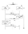
- FIG. 15 is a sequence diagram when a data stream is distributed from the server-side AV device of FIG. 14 to the client-side AV device.
- (A), (b), (c) is a figure for demonstrating an example of control of the data rate at the time of the transmission throughput fall.
- (A), (b), (c) is a figure for demonstrating an example of control of the data rate at the time of the increase in transmission throughput.
- a transmission device that transmits data to a transmission line, a buffer that temporarily holds data transmitted to the transmission line, and a predetermined time output from the buffer.
- a first detection unit for detecting an output rate value representing the data amount of the data
- a second detection unit for detecting a free space value of the buffer, and the free space value detected by the second detection unit.
- a reduction rate calculation unit that calculates a value of the reduction rate of the free space by dividing a subtraction value obtained by subtracting a predetermined first set value from a predetermined securing time, and the output detected by the first detection unit
- the input rate representing the amount of data per predetermined time input to the buffer is lowered according to the value of the rate, the value of the output rate detected by the first detection unit and the decrease rate performance are detected.
- Adding the value of the reduction ratio calculated by the section, and a control unit which performs rate control processing for controlling the input rate on the basis of the first control value is a sum value.
- a first rate control device includes a buffer that temporarily holds data transmitted to a transmission path, and an output rate that represents the amount of data per predetermined time output from the buffer.
- a first detection unit for detecting a value, a second detection unit for detecting a free space value of the buffer, and a predetermined first set value is subtracted from the free space value detected by the second detection unit.
- a reduction rate calculation unit that calculates a value of the reduction rate of the free space by dividing the subtraction value by a predetermined reserved time, and input to the buffer according to the value of the output rate detected by the first detection unit
- the output rate value detected by the first detection unit and the reduction rate value calculated by the reduction rate calculation unit It adds, and a control unit which performs rate control processing for controlling the input rate on the basis of the first control value is a sum value.
- a first transmission method is a transmission method performed in a transmission device that transmits data to a transmission path, and temporarily holds data transmitted to the transmission path in a buffer;
- a first detection step for detecting an output rate value representing a data amount of data per predetermined time output from the buffer, a second detection step for detecting a free capacity value of the buffer, and the second detection
- a reduction rate calculation step of calculating a value of the reduction rate of the free space by dividing a subtraction value obtained by subtracting a predetermined first set value from the value of the free space detected in the step by a predetermined securing time;
- the input rate representing the amount of data per predetermined time input to the buffer is lowered according to the value of the output rate detected in the first detection step.
- the value of the output rate detected in the first detection step and the value of the decrease rate calculated in the decrease rate calculating step are added, and the input rate is determined based on the first control value which is an added value.
- a control step for performing a rate control process for controlling is performed.
- a second transmission device uses the first transmission device to calculate the value of the free capacity detected by the second detection unit from a predetermined second setting value that is larger than the first setting value.
- the output rate detected by the first detection unit is further provided with an increase rate calculation unit that calculates a value of the increase rate of the free space by dividing the subtracted subtraction value by a predetermined secured time.
- the increase rate value calculated by the increase rate calculation unit is subtracted from the output rate value detected by the first detection unit to obtain a subtraction value. 2 Control the input rate based on the control value.
- a third transmission device is the first transmission device, wherein the control unit is configured such that the value of the free space detected by the second detection unit is smaller than a predetermined first threshold value. The rate control process is performed.
- the transmission throughput is stable when the value of the free capacity of the buffer is equal to or greater than the first threshold, and the input rate is not changed while the transmission throughput is stable.
- the control unit is configured such that the value of the free space detected by the second detection unit is equal to or greater than a predetermined second threshold value.
- the input rate is controlled so that the value of the input rate is fixed or becomes a predetermined value.
- the free space value of the buffer is equal to or larger than the second threshold, it is determined that the transmission throughput is stable, and the input rate is not changed while the transmission throughput is stable. Thereby, even if the transmission throughput fluctuates while the transmission throughput is stable, the data rate of the data to be transmitted corresponding to the input rate can be kept constant.
- a fifth transmission device is the second transmission device, wherein the control unit is configured such that when the current input rate value exceeds the first control value, the input rate value is The input rate is controlled to be the first control value, and when the current input rate value is lower than the second control value, the input rate value is set to the second control value. To control.
- a sixth transmission device is the fifth transmission device, wherein the control unit is configured such that when the current input rate value is greater than or equal to the second control value and less than or equal to the first control value, The input rate is controlled so that the value of the input rate is maintained.
- a seventh transmission device in the first transmission device, when the control unit exceeds a value of a maximum data rate that can be set for data to be transmitted, the input is performed.
- the input rate is controlled so that the rate value becomes the maximum data rate value.
- An eighth transmitting apparatus is the second transmitting apparatus, wherein the control unit is configured to input the input when the second control value exceeds a maximum data rate that can be set for data to be transmitted. The input rate is controlled so that the rate value becomes the maximum data rate value.
- a first receiving device which is one embodiment of the present invention is a receiving device which receives data from a transmission path, a buffer that temporarily holds data received from the transmission path, and a predetermined time input to the buffer.
- a first detection unit that detects a value of an input rate that represents a data amount of the data; a second detection unit that detects a value of a storage amount of data in the buffer; and the storage amount detected by the second detection unit
- a reduction rate calculation unit that calculates a value of the reduction rate of the accumulated amount by dividing a subtracted value obtained by subtracting a predetermined first set value from the value of the value by a predetermined securing time, and is detected by the first detection unit
- the input rate value detected by the first detector and the decrease The value of the decrease rate calculated by the rate calculating unit is added, an update value of the output rate to be updated is determined based on the first control value that is the added value, and the determined output rate
- a second rate control device includes a buffer that temporarily holds data received from a transmission path, and an input rate that represents a data amount of data per predetermined time input to the buffer.
- a first detection unit that detects a value
- a second detection unit that detects a value of the accumulated amount of data in the buffer, and a predetermined first set value from the value of the accumulated amount detected by the second detection unit.
- a reduction rate calculation unit that calculates a value of the reduction rate of the accumulated amount by dividing the subtracted subtraction value by a predetermined securing time; and the buffer according to the value of the input rate detected by the first detection unit When the output rate representing the data amount of the data output from the predetermined time is lowered, the value of the input rate detected by the first detection unit and the reduction rate calculated by the reduction rate calculation unit And an update value of the output rate for which the output rate is to be updated is determined based on the first control value that is the addition value, and the determined update value of the output rate is notified to the transmission device.
- a control unit that performs rate control processing.
- a first reception method is a reception method performed in a reception device that receives data from a transmission line, and temporarily holds data received from the transmission line in a buffer;
- a first detection step for detecting a value of an input rate representing a data amount of data per predetermined time input to the buffer;
- a second detection step for detecting a value of an accumulated amount of data in the buffer;
- a reduction rate calculating step of calculating a value of the reduction rate of the accumulated amount by dividing a subtracted value obtained by subtracting a predetermined first set value from the accumulated amount value detected in two detection steps by a predetermined secured time;
- the value of the input rate detected in the first detection step and the value of the decrease rate calculated by the decrease rate calculation unit are added, and the value is calculated based on the first control value that is an added value.
- the second receiving device is configured to obtain the value of the accumulated amount detected by the second detection unit from a predetermined second setting value larger than the first setting value in the first receiving device.
- the control apparatus further includes an increase rate calculation unit that calculates a value of the increase rate of the accumulated amount by dividing the subtracted subtraction value by a predetermined secured time, and the control unit detects the input rate detected by the first detection unit.
- the increase rate value calculated by the increase rate calculation unit is subtracted from the input rate value detected by the first detection unit to obtain a subtraction value. 2
- An update value of the output rate is determined based on the control value, and the determined update value of the output rate is notified to the transmission apparatus.
- the control unit detects that the accumulated amount detected by the second detecting unit is smaller than a predetermined first threshold value. The rate control process is performed.
- the transmission throughput is stable when the value of the buffer accumulation amount is equal to or greater than the first threshold, and the output rate is not changed while the transmission throughput is stable.
- the data rate of the data to be transmitted corresponding to the output rate can be kept constant.
- the control unit is configured such that the accumulated amount detected by the second detecting unit is equal to or greater than a predetermined second threshold value.
- the update value of the output rate is determined so that the value of the output rate is fixed or becomes a predetermined value.
- the transmission throughput is stable when the value of the buffer accumulation amount is equal to or greater than the second threshold, and the output rate is not changed while the transmission throughput is stable.
- the data rate of the data to be transmitted corresponding to the output rate can be kept constant.
- the control unit when the current output rate value exceeds the first control value, sets the updated output rate value.
- the first control value is determined, and when the current output rate value is lower than the second control value, the output rate update value is determined as the second control value.
- the control unit in the fifth receiving apparatus, is configured so that the current output rate value is equal to or greater than the second control value and equal to or less than the first control value.
- the update value of the output rate is determined so that the value of the output rate is maintained.
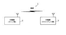
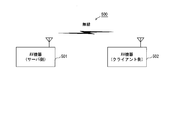
- FIG. 1 is a network configuration diagram according to the present embodiment.
- the network 1 includes AV devices 2 and 3.
- the AV device 2 is a server-side AV device that stores and holds media data and transmits media data.
- the AV device 3 receives and receives media data transmitted from other devices. It is an AV device on the client side that reproduces and displays the media data.
- the AV device 2 is, for example, an HDD (Hard Disk Drive) recorder device or a Blu-ray Disk (registered trademark) recorder device capable of storing video content data having a communication function.
- the AV device 3 is a display device such as a television having a communication function.
- Communication functions include wireless communication such as IEEE 802.11 standard wireless LAN (Local Area Network), power line communication such as HD-PLC (registered trademark), communication such as Ethernet (registered trademark), coaxial cable communication, etc.
- wireless communication such as IEEE 802.11 standard wireless LAN (Local Area Network), power line communication such as HD-PLC (registered trademark), communication such as Ethernet (registered trademark), coaxial cable communication, etc.
- the communication function is represented by wireless communication.
- the AV device 2 performs streaming distribution of the stored video content data
- the AV device 3 receives the streamed video content data, and reproduces and displays the received video content data.
- the viewer can view the video content data stored in the AV device 2 on the AV device 3.
- the AV device 3 on the client side can use a general AV device, and detailed description thereof is omitted.
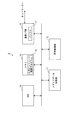
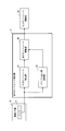
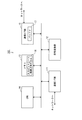
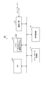
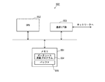
- ⁇ Device configuration of AV equipment (server side)> 2 is a device configuration diagram of the server-side AV device 2 of FIG. 1.
- the AV device 2 includes a media data storage unit 11, a code conversion unit 12, a memory 13, a CPU (Central Processing Unit) 14, And a communication interface unit (hereinafter referred to as “communication I / F unit”) 15.
- communication I / F unit communication interface unit
- the media data storage unit 11 is constructed of, for example, an HDD, and has a function of storing and holding media contents such as video data and audio data.
- the code conversion unit 12 has a function of converting a bit rate (data rate) of media data such as video data and audio data.
- the media data bit rate can be converted by once decoding the compressed and encoded media data and re-encoding it to a different bit rate, or by trans-encoding the media data to a different bit rate without decoding it.
- coding there is a method called coding, etc.
- any conversion method or encoding method may be used as long as input media data can be converted into media data of different bit rates and output.
- video data and audio data input to the code conversion unit 12 do not necessarily have to be compressed and encoded.
- uncompressed and encoded video data and audio data may be input, compression and encoding processing may be performed, and compressed and encoded video data and audio data may be output.
- the memory 13 is constructed by a semiconductor memory such as ROM (Read Only Memory) or RAM (Random Access Memory).
- the memory 13 stores programs such as various control programs and various application programs. For example, the memory 13 controls the data amount of media data per predetermined time input to a buffer 17 described later in the communication I / F unit 15.
- a program hereinafter referred to as “input bit rate control program”
- the memory 13 has an area used when the CPU 14 operates.
- the CPU 14 has a function of performing various controls and various calculations of the entire AV device 2 by reading the program stored in the memory 13 and executing the read program. For example, the CPU 14 reads the input bit rate control program 16 from the memory 13 and executes the read input bit rate control program 16. This process will be described later with reference to FIGS.
- the communication I / F unit 15 has a function of transmitting and receiving data via a network, for example, a function of performing modulation / demodulation of a data signal and media access control, and is a communication I / F unit for wireless communication here.
- the communication I / F unit 15 has a buffer 17 therein, and the buffer 17 is a transmission buffer. The buffer 17 will be described later with reference to FIG.
- the CPU 14 executes an input bit rate control program 16 to calculate an input bit rate update value, which will be described later, and the code conversion unit 12 calculates the calculated input bit rate.
- Bit rate (data rate) conversion is performed on the media data stored and held in the media data storage unit 11 in accordance with the updated value.
- the communication I / F unit 15 then sends the media data obtained by the conversion to the AV device 3 on the client side via the network while temporarily storing it in the buffer 17.
- the code conversion unit 12 that changes the bit rate (data rate) of the data input to the buffer 17 in the AV device 2, the input bit rate can be changed immediately.
- FIG. 3 is a diagram for explaining a configuration example of the buffer 17 of FIG.
- the storage amount 21 represents the data amount of data stored in the buffer 17, and the buffer free space 22 represents the data amount of remaining data that can be stored in the buffer 17.
- the unit of the data amount can be expressed by bits or bytes for both the storage amount 21 and the buffer free capacity 22, and will be described using bits in this embodiment.
- the input bit rate 23 represents the data amount per unit time of the media data input to the buffer 17, and the output bit rate 24 represents the data amount per unit time of the media data output from the buffer 17.
- bps bit per second
- the input bit rate 23 is equal to the bit rate (data rate) of the media data output from the code conversion unit 12, and the output bit rate 24 is the transmission throughput when the communication I / F unit 15 transmits the media data. Suppose they are equal.
- the buffer 17 outputs the input media data in the input order in accordance with the operation principle of FIFO (First In First Out).
- FIFO First In First Out
- the accumulation amount 21 of the buffer 17 does not change.
- the accumulation amount 21 of the buffer 17 increases or decreases according to the difference between the input bit rate 23 and the output bit rate 24. That is, when the input bit rate 23 is greater than the output bit rate 24, the accumulation amount 21 of the buffer 17 increases, and when the input bit rate 23 is less than the output bit rate 24, the accumulation amount 21 of the buffer 17 decreases.
- the accumulated amount 21 of the buffer 17 increases at a speed of 4 Mbps, in other words, the buffer free capacity 22 of the buffer 17 decreases at a speed of 4 Mbps.
- the input bit rate 23 is 6 Mbps and the output bit rate 24 is 9 Mbps
- the accumulated amount 21 of the buffer 17 decreases at a speed of 3 Mbps, in other words, the buffer free capacity 22 of the buffer 17 increases at a speed of 3 Mbps.
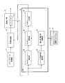
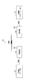
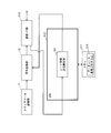
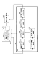
- FIG. 4 is a functional configuration diagram of the CPU 14 of FIG. However, FIG. 4 also illustrates other components of the AV device 2 in order to facilitate understanding of the functional configuration of the CPU 14.
- the CPU 14 reads the input bit rate control program 16 stored and held in the memory 13 and executes the read input bit rate control program 16.
- the CPU 14 functions as an output bit rate detection unit 31, a buffer free space detection unit 32, a decrease rate / increase rate calculation unit 33, an input bit rate calculation unit 34, and an input bit rate determination unit 35.
- the output bit rate detection unit 31 detects the value of the output bit rate 24 of the media data output from the buffer 17, that is, the value of the transmission throughput, and outputs the detected value of the output bit rate 24 to the input bit rate calculation unit 34. .
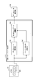
- FIG. 5 is a functional configuration diagram of the output bit rate detection unit 31 of FIG.
- the communication I / F unit 15 and the input bit rate calculation are performed. Part 34 is also illustrated.
- the output bit rate detection unit 31 functions as an input bit rate detection unit 41, a buffer change rate calculation unit 42, and an output bit rate calculation unit 43.
- the input bit rate detection unit 41 detects the data amount per unit time of the media data input to the buffer 17 and outputs the detection result to the output bit rate calculation unit 43 as the value of the input bit rate 23. Note that the input bit detection unit 41 may detect an input bit rate update value (described later) output from the input bit rate determination unit 35 to the code conversion unit 12 as the value of the input bit rate 23.
- the buffer change rate calculation unit 42 calculates an increase or decrease in the accumulated amount 21 of the buffer 17 per unit time as the change rate, and outputs the calculated change rate value to the output bit rate calculation unit 43.
- the rate of change when the accumulated amount 21 increases is represented by a positive value
- the rate of change when the accumulated amount 21 decreases is represented by a negative value.
- the buffer free capacity detection unit 32 detects the value of the buffer free capacity 22 of the buffer 17 and outputs the detected value of the buffer free capacity 22 to the decrease rate / increase rate calculation unit 33.
- the decrease rate / increase rate calculation unit 33 uses the value of the buffer free space 22 of the buffer 17 input from the buffer free space detection unit 32 and the value of the allowable decrease rate of the buffer free space 22 of the buffer 17 and The increase rate value is calculated, and the calculated decrease rate value and increase rate value are output to the input bit rate calculation unit 34.
- the decrease rate / increase rate calculation unit 33 calculates the increase rate as follows.
- the increase rate set value is the maximum value of the target buffer free space 22 after the secured time by adjusting the increase / decrease of the buffer free space 22 by controlling the input bit rate 23, and the increase rate set value is mainly This is used when performing control to increase the input bit rate.
- the calculated increase rate value is a value of the increase rate of the buffer free space 22 per unit time required when the value of the buffer free space 22 is increased to the increase rate set value after the secured time. .
- the decrease rate / increase rate calculation unit 33 calculates the decrease rate as follows.
- the decrease rate / increase rate calculation unit 33 calculates a decrease rate value by subtracting a preset decrease rate set value from the value of the buffer free capacity 22 of the buffer 17 and dividing the subtracted value by the reserved time.
- (Decrease rate (buffer free capacity ⁇ decrease rate setting value) / reserved time).
- the decrease rate setting value is the minimum value of the target buffer free space 22 after adjusting the increase / decrease of the buffer free space 22 by controlling the input bit rate 23, and the decrease rate set value is mainly This is used when performing control to lower the input bit rate.
- the calculated decrease rate value is a decrease rate value of the buffer free space 22 per unit time required when the value of the buffer free space 22 is to be decreased to the decrease rate set value after the secured time. .
- the increase rate set value is larger than the decrease rate set value.
- the increase rate set value can be set to an arbitrary value at the time of design.
- the increase rate set value may be set as the maximum accumulation amount of the buffer 17.
- the reduction rate setting value can be set to an arbitrary value at the time of design, for example, the reduction rate setting value may be set to zero.
- the securing time used for calculating the increase rate and the decrease rate can be set to an arbitrary value at the time of design, but can be set as, for example, the duration of a transmission path error that occurs continuously.
- the securing time used for calculating the increase rate and the securing time used for calculating the decrease rate may be the same value or different values.
- the input bit rate calculation unit 34 adds the decrease rate value input from the decrease rate / increase rate calculation unit 33 to the output bit rate value input from the output bit rate detection unit 31, and uses the added value as the input bit rate.
- the input bit rate upper limit value is an upper limit value of the input bit rate allowed when the input bit rate is updated.
- the input bit rate calculation unit 34 subtracts the increase rate value input from the decrease rate / increase rate calculation unit 33 from the output bit rate value input from the output bit rate detection unit 31 and inputs the subtraction value.
- the input bit rate lower limit value is a lower limit value of the input bit rate that is allowed when the input bit rate is updated.
- the input bit rate determination unit 35 includes the current input bit rate value detected by the input bit rate detection unit 41 in FIG. 5, the input bit rate upper limit value and the input bit rate lower limit value input from the input bit rate calculation unit 34.
- the input bit rate update value is determined based on the value and the value of the maximum data rate that can be set for the media data to be transmitted, and the determined input bit rate update value is notified to the code conversion unit 12. However, the input bit rate update value output to the code conversion unit 12 may be used as the current input bit rate value.
- the code conversion unit 12 converts the bit rate (data rate) of the media data stored in the media data storage unit 11 according to the input bit rate update value notified from the input bit rate determination unit 35 of the CPU 14 and converts the bit rate.
- the media data obtained by the above is output to the buffer 17 in the communication I / F unit 15.
- the input bit rate determination unit 35 sets the input bit rate update value to the current input bit rate value. Set to. If the current input bit rate value is smaller than the input bit rate lower limit value, the input bit rate determining unit 35 sets the input bit rate update value to the input bit rate lower limit value, and the current input bit rate value is set to the input bit rate. If it is larger than the rate upper limit value, the input bit rate update value is set to the input bit rate upper limit value.
- the input bit rate determination unit 35 sets the input bit rate update value to the maximum data rate value. Reset to.
- the configuration of the CPU 14 described with reference to FIGS. 4 and 5 it is only necessary to detect the buffer state such as the buffer free capacity 22 of the buffer 17, the input bit rate 23, and the rate of change of the buffer free capacity 22 of the buffer 17.
- the input bit rate can be controlled. For this reason, control of the input bit rate is facilitated, and the configuration of the AV device 2 can be simplified.
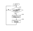
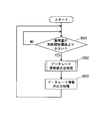
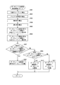
- FIG. 6 is a flowchart showing the flow of input bit rate control processing performed by the CPU 14 of FIG. However, the CPU 14 reads the input bit rate control program 16 stored in the memory 13 and executes the read input bit rate control program 16, thereby executing the processing of the flowchart of FIG. 6 and FIG.
- the CPU 14 determines whether or not the value of the buffer free space 22 of the buffer 17 is smaller than a preset control start threshold (step S101).
- step S101 While the value of the buffer free space 22 is equal to or greater than the control start threshold (S101: NO), the process of step S101 is repeated and the input bit rate 23 is not updated. For example, it is determined that the transmission throughput is stable until the value of the buffer free capacity 22 becomes smaller than the control start threshold, and the input bit rate 23 is not updated. Further, when the transmission path state is recovered and the value of the buffer free capacity 22 becomes equal to or greater than the control start threshold, the transmission throughput is stable until the value of the buffer free capacity 22 becomes smaller than the control start threshold again. Thus, the value of the input bit rate 23 is fixed at the value of the input bit rate 23 at the time when the value of the buffer free space 22 becomes equal to or greater than the control start threshold value.
- the buffer free capacity 22 of the buffer 17 when the value of the buffer free capacity 22 of the buffer 17 is equal to or greater than the control start threshold, it is determined that the transmission throughput is stable, and the buffer free capacity 22 of the buffer 17 when the transmission throughput is stable is determined.
- the input bit rate 23 is not updated for instantaneous fluctuations. For this reason, the input bit rate 23 is kept constant when the transmission throughput is stable.
- the CPU 14 executes the input bit rate update value determination process whose process flow is shown in FIG. A rate update value is determined (step S102). Then, the input bit rate determination unit 35 of the CPU 14 notifies the code conversion unit 12 of the input bit rate update value determined in step S102 (step S103), and the process of step S101 is performed.
- the code conversion unit 12 converts the bit rate (data rate) of the media data stored in the media data storage unit 11 according to the notified input bit rate update value, and converts the media data obtained by the conversion to the communication I / F.
- the data is output to the buffer 17 in the unit 15.
- the communication I / F unit 15 transmits the media data stored in the buffer 17 to, for example, the AV device 3 on the client side via the network.
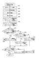
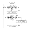
- FIG. 7 is a flowchart showing the flow of the input bit rate update value determination process (step S102) of FIG.
- the input bit rate detector 41 detects the value of the input bit rate 23 of the media data input to the buffer 17, and the buffer change rate calculator 42 changes the accumulated amount 21 of the buffer 17. Calculate the rate value. Then, the output bit rate calculation unit 43 calculates the value of the output bit rate 24 by subtracting the calculated change rate value from the detected value of the input bit rate 23 (step S201).
- the buffer free capacity detection unit 32 detects the value of the buffer free capacity 22 of the buffer 17 (step S202).
- the decrease rate / increase rate calculation unit 33 calculates the value of the increase rate by subtracting the value of the buffer free space 22 detected in step S202 from the increase rate set value and dividing the subtracted value by the reserved time (Step S203). Further, the decrease rate / increase rate calculation unit 33 subtracts the decrease rate set value from the value of the buffer free space 22 detected in step S202, and calculates the decrease rate value by dividing the subtracted value by the reserved time. (Step S204).
- the input bit rate calculation unit 34 adds the value of the decrease rate calculated in step S204 to the value of the output bit rate detected in step S201, and sets the added value as the input bit rate upper limit value (step S205). Further, the input bit rate calculation unit 34 subtracts the value of the increase rate calculated in step S203 from the value of the output bit rate detected in step S201, and sets the subtraction value as the input bit rate lower limit value (step S206). .
- the input bit rate determination unit 35 determines whether or not the current input bit rate value is within a range not less than the input bit rate lower limit value obtained in step S206 and not more than the input bit rate upper limit value obtained in step S205 ( Step S207).
- the input bit rate determination unit 35 sets the input bit rate update value to the current input bit rate value (step S208). The process proceeds to S212.
- the current input bit rate value is greater than or equal to the input bit rate lower limit value. If it is within the following range, the input bit rate is not updated. For this reason, if the current input bit rate value is within the above range, the input bit rate is stable without fluctuation even if the transmission throughput varies. As a result, for example, it is possible to avoid a situation in which the resolution and frame rate of the video reproduced by the AV device 3 on the client side suddenly increase or decrease, and the viewer can view the video with stable quality.
- the input bit rate determination unit 35 determines whether or not the current input bit rate value is greater than the input bit rate upper limit value (Ste S209).
- the input bit rate determination unit 35 sets the input bit rate update value to the input bit rate upper limit value to lower the input bit rate (step S210), and proceeds to the process of step S212. To do.
- the input bit rate determination unit 35 is configured to increase the input bit rate.
- the update value is set to the input bit rate lower limit value (step S211), and the process proceeds to step S212.
- the input bit rate determination unit 35 determines whether the input bit rate update value set in step S208, step S210, or step S211 is greater than the maximum data rate that can be set for the media data to be transmitted (step S212). . If the set input bit rate update value is larger than the maximum data rate value (S212: YES), the input bit rate determination unit 35 resets the input bit rate update value to the maximum data rate value (step S213). Step S103 of FIG. 6 is performed. By doing in this way, since the input bit rate update value notified to the code conversion unit 12 does not exceed the maximum data rate value, the input bit rate update value at which the code conversion unit 12 exceeds the maximum data rate value.
- step S103 in FIG. 6 is performed without resetting the input bit rate update value.
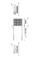
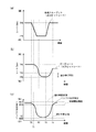
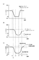
- FIGS. 8A and 9 (a) are diagrams showing the transmission throughput, that is, the temporal variation of the output bit rate 24 of the media data output from the buffer 17, and the vertical axis indicates the rate (bps) and the horizontal axis. Represents time.
- the transmission path state deteriorates at time T0 and the transmission throughput starts to drop sharply, and the transmission path state recovers at time T3 after a certain period of time for transmission. It shows how the throughput is starting to rise sharply.
- FIGS. 8B and 9B are diagrams showing temporal fluctuations in the data rate of media data to be transmitted, that is, the input bit rate 23 of media data input to the buffer 17, and the vertical axis indicates the rate. (Bps), the horizontal axis represents time.
- 8 (c) and 9 (c) are diagrams showing temporal fluctuations of the buffer free capacity 22 of the buffer 17, where the vertical axis represents the buffer free capacity and the horizontal axis represents the time.
- the transmission path state deteriorates, the transmission throughput, that is, the output bit rate 24 of the media data output from the buffer 17, starts to decrease, and the value of the output bit rate 24 decreases from TPA to TPB.
- the buffer free space 22 decreases. Since the value of the buffer free capacity 22 is equal to or greater than the control start threshold value RTH until time T1, the value of the input bit rate 23 remains unchanged (see step S101 in FIG. 6). As described above, while the value of the buffer free capacity 22 is equal to or greater than the control start threshold value RTH, the value of the input bit rate 23 does not decrease even if the value of the output bit rate 24 decreases.
- the value of the buffer free space 22 decreases according to the difference between the value of the input bit rate 23 and the value of the output bit rate 24, and the value of the buffer free space 22 falls below the control start threshold value RTH at time T1.
- the CPU 14 starts the determination of the input bit rate update value and the notification of the input bit rate update value to the code converter 12, and determines the input bit rate update value until the value of the buffer free capacity 22 becomes equal to or greater than the control start threshold value RTH.
- the input bit rate update value is notified to the code converter 12 (see FIG. 6).
- the output bit rate detection unit 31 of the CPU 14 detects the value of the output bit rate 24, the buffer free capacity detection unit 32 detects the value of the buffer free capacity 22 of the buffer 17, and the decrease rate / increase rate calculation unit 33 calculates the increase rate.
- the input bit rate calculation unit 34 calculates the input bit rate upper limit value and the input bit rate lower limit value (see step S201 to step S206 in FIG. 7).
- the input bit rate determination unit 35 assumes that the current input bit rate value is larger than the input bit rate upper limit value, and sets the input bit rate update value to the input bit rate upper limit value (steps S207 and S209 in FIG. 7). , S210).
- the input bit rate determination unit 35 assumes that the input bit rate update value is equal to or less than the maximum data rate value (see step S212 in FIG. 7), and updates the input bit rate without resetting the input bit rate update value.
- a value here, a value equal to the input bit rate upper limit value
- the code conversion unit 12 see step S103 in FIG. 6
- the value of the input bit rate 23 is gradually smaller than the value of the output bit rate 24.
- the reduction rate setting value is RDW
- the securing time is Ta
- the buffer free capacity 22 of the buffer 17 at time T2 is R2
- the output bit rate 24 at time T2 is TPB.
- TPD2 (R2-RDW) / Ta.
- the upper limit value of the input bit rate at time T2 is an addition value TPB + TPD2 obtained by adding the value of the subtraction rate (TPD2) at time T2 to the value of output bit rate 24 at time T2 (TPB).
- TPD2 subtraction rate
- the transmission throughput is recovered from the state where the transmission throughput is lowered due to the deterioration of the transmission path state, along with the recovery of the transmission path state.
- the output bit rate detection unit 31 of the CPU 14 detects the value of the output bit rate
- the buffer free capacity detection unit 32 detects the value of the buffer free capacity 22 of the buffer 17, and the decrease rate / increase rate calculation unit 33 calculates the increase rate.
- the input bit rate calculation unit 34 calculates the input bit rate upper limit value and the input bit rate lower limit value (see Step S201 to Step S206 in FIG. 7).
- the input bit rate determination unit 35 assumes that the current input bit rate value is smaller than the input bit rate lower limit value, and sets the input bit rate update value to the input bit rate lower limit value (steps S207 and S209 in FIG. 7). , S211).
- the input bit rate determination unit 35 assumes that the input bit rate update value is equal to or less than the maximum data rate value (see step S212 in FIG. 7), and updates the input bit rate without resetting the input bit rate update value.
- a value here, a value equal to the input bit rate lower limit value
- the code conversion unit 12 see step S103 in FIG. 6.
- the value of the input bit rate 23 gradually increases with a smaller value than the value of the output bit rate 24.
- the increase rate setting value is RUP
- the securing time is Ta
- the buffer free capacity 22 of the buffer 17 at time T4 is R4
- the output bit rate 24 at time T4 is TPA.
- TPU4 (RUP ⁇ R4) / Ta.
- the input bit rate lower limit value at time T4 is a subtracted value TPA-TPU4 obtained by subtracting the value of the increase rate (TPU4) at time T4 from the value of output bit rate 24 at time T4 (TPA).
- TP4 TPA-TPU4.
- the buffer free space 22 starts to increase.
- the value of the buffer free capacity 22 of the buffer 17 becomes equal to or greater than the control start threshold value RTH at time T5
- the value of the input bit rate is fixed (see step S101 in FIG. 6).
- the maximum data rate value is 12 Mbps
- the maximum accumulation amount of the buffer 17 is 500 packets (hereinafter referred to as “Pkt”)
- the control start threshold is 450 Pkt
- the increase rate set value is 500 Pkt
- the decrease rate The set value is 50 Pkt and the securing time is 500 msec.
- 1 Pkt is 1500 bytes.
- CPU 14 calculates the decrease rate and the input bit rate upper limit value.
- the CPU 14 calculates an increase rate and an input bit rate lower limit value.
- the current input bit rate 23 value is 12 Mbps
- the transmission throughput is 6 Mbps due to the deterioration of the transmission path state
- the buffer free space 22 of the buffer 17 is 250 Pkt.
- CPU 14 calculates the decrease rate and the input bit rate upper limit value.
- the CPU 14 calculates an increase rate and an input bit rate lower limit value.
- CPU 14 calculates the decrease rate and the input bit rate upper limit value.
- the CPU 14 calculates an increase rate and an input bit rate lower limit value.
- the CPU 14 sets the input bit rate update value to the current value.
- the value of the input bit rate 23 is “3 Mbps”.
- the CPU 14 keeps the input bit rate update value at 3 Mbps.
- the current input bit rate 23 is 3 Mbps
- the transmission throughput is 12 Mbps due to the recovery of the transmission path state
- the buffer free space 22 of the buffer 17 is 150 Pkt.
- CPU 14 calculates the decrease rate and the input bit rate upper limit value.
- the CPU 14 calculates an increase rate and an input bit rate lower limit value.
- the data rate of the media data that is, the media data input to the buffer 17, prevents overflow of the buffer 17.
- the input bit rate 23 is controlled so that the input bit rate 23 decreases.
- the input bit rate 23 is not lowered so that the value of the input bit rate 23 becomes the value of the output bit rate 24 as in the prior art, but the buffer free capacity 22 of the buffer 17 is used.
- the value of the input bit rate 23 is lowered so that the value of the input bit rate 23 becomes larger than the value of the output bit rate 24.
- the value of the reduction rate is calculated such that the value of the buffer free capacity 22 of the buffer 17 becomes the reduction rate setting value after the above-described securing time, and the current value of the input bit rate 23 is calculated as the value of the reduction rate.
- the input bit rate 23 is controlled so that the value of the input bit rate 23 becomes the input bit rate upper limit value.
- the value of the buffer free capacity 22 of the buffer 17 increases or decreases in accordance with the difference between the value of the input bit rate 23 and the value of the output bit rate 24, so the value of the input bit rate 23 becomes the input bit rate upper limit value. In such a control, even if the transmission throughput does not change, the buffer free capacity 22 of the buffer 17 decreases according to the decrease rate.
- the value of the subtraction rate to be added to the value of the output bit rate 24 increases when the value of the buffer free capacity 22 of the buffer 17 is large.
- the input bit rate upper limit value becomes large.
- the transmission bit rate is temporarily lowered, the input bit rate is reduced as compared with the case where the input bit rate is lowered so that the value of the input bit rate 23 becomes the value of the transmission throughput, that is, the output bit rate 24.
- the temporal variation of the input bit rate can be reduced.
- the transmission throughput temporarily decreases during the distribution of the video data, it is possible to reduce the amount of reduction in the resolution and frame rate of the video reproduced on the receiving side, and the viewer can achieve stable quality. You can watch the video.
- the value of the buffer free capacity 22 of the buffer 17 is small, the value of the decrease rate added to the value of the output bit rate is small, but the range in which the value of the buffer free capacity 22 of the buffer 17 does not fall below the decrease rate set value. To reduce the difference between the input bit rate value and the output bit rate value. For this reason, even if the value of the buffer free capacity 22 of the buffer 17 decreases as the transmission throughput continues to decrease for a certain period, the value of the buffer free capacity 22 of the buffer 17 decreases only to the reduction rate setting value. 17 overflow does not occur.
- the packet 17 is prevented from being lost without reaching the receiving side due to overflow of the buffer 17, and the viewer is not interrupted. You can watch the video.
- the value of the buffer free capacity 22 of the buffer 17 becomes the decrease rate setting value after the securing time
- the decrease rate of the buffer free capacity 22 gradually increases as the value of the buffer free capacity 22 of the buffer 17 decreases. Therefore, the value of the input bit rate 23 can be gradually reduced.
- the transmission throughput is reduced during transmission of video data
- the resolution and frame rate of the video reproduced on the receiving side can be lowered gradually, and the uncomfortable feeling felt by the viewer can be reduced.
- the decrease rate setting value By setting the decrease rate setting value to zero, the value of the decrease rate of the buffer free space 22 when the value of the buffer free space 22 of the buffer 17 becomes the decrease rate set value after the securing time is maximized. be able to. For this reason, the amount of decrease in the value of the input bit rate can be minimized as compared with the case where the decrease rate setting value is set to a value larger than zero.
- the output bit rate 24 of the media data output from the buffer 17 increases, for example, if video data is being distributed, a high-quality video is provided to the viewer.
- the input bit rate 23 is controlled so that the data rate of the media data, that is, the input bit rate 23 of the media data input to the buffer 17 is increased.
- the input bit rate 23 is not increased so that the value of the input bit rate 23 becomes the value of the output bit rate 24 as in the prior art, but the buffer free capacity 22 of the buffer 17 is used.
- the value of the input bit rate 23 is increased so that the value of the input bit rate 23 becomes smaller than the value of the output bit rate 24.
- the value of the increase rate is calculated such that the value of the buffer free capacity 22 of the buffer 17 becomes the increase rate set value after the above securing time, and the current input bit rate 23 value is the output bit rate 24 value.
- the input bit rate 23 is controlled so that the value of the input bit rate 23 becomes the input bit rate lower limit value.
- the value of the buffer free capacity 22 of the buffer 17 increases or decreases according to the difference between the value of the input bit rate 23 and the value of the output bit rate 24, so the value of the input bit rate 23 becomes the input bit rate lower limit value. In such a control, even if the transmission throughput does not change, the buffer free capacity 22 of the buffer 17 increases according to the increase rate.
- the value of the buffer free capacity 22 of the buffer 17 is set to an increase rate set value larger than the decrease rate set value after the securing time.
- the increase rate of the buffer free capacity 22 gradually decreases as the value of the buffer free capacity 22 of the buffer 17 increases. For this reason, the value of the input bit rate 23 can be increased gradually.
- the resolution and frame rate of the video played back on the receiving side can be increased gradually, reducing the sense of discomfort felt by the viewer. it can.
- the increase rate setting value as the maximum accumulation amount of the buffer 17
- the value of the buffer free capacity 22 of the buffer 17 when the transmission throughput is recovered can be maximized.
- the capacity can be used most effectively.
- the input bit rate 23 From the control state in which the input bit rate 23 is increased so that the value of the input bit rate 23 is always a value obtained by subtracting the value of the increase rate of the buffer free capacity 24 from the value of the output bit rate 24, the input bit rate 23
- the value of the input bit rate 23 is A value obtained by subtracting the value of the increase rate of the buffer free space 22 from the value of the bit rate 24 is changed to a value obtained by adding the value of the decrease rate of the buffer free space 22 to the value of the output bit rate 24.
- the value of the input bit rate 23 increases by a value obtained by adding the increase rate value and the decrease rate value, and increases rapidly. For this reason, at the timing when the transmission throughput is lowered, the resolution and frame rate of the video reproduced by the AV device 3 on the client side are rapidly increased.
- the output is While the added value (input bit rate upper limit value) obtained by adding the value of the decrease rate of the buffer free capacity 22 of the buffer 17 to the value of the bit rate 24 is larger than the value of the current input bit rate 23, the current input bit rate 23 I try to maintain the value of.
- the input bit rate update value is set as the input bit rate upper limit value, and the current input bit rate 23 value is less than or equal to the input bit rate upper limit value. If there is, the input bit rate update value is set as the current input bit rate value.
- the input bit rate 23 is switched to a control state in which the input bit rate 23 is increased so that the value of the output bit rate 24 is always subtracted from the value of the increase rate of the buffer free space 24 from the value of the output bit rate 24, the value of the input bit rate 23 is It changes from the value obtained by adding the value of the decrease rate of the buffer free space 22 to the value of the output bit rate 24 to the value obtained by subtracting the value of the increase rate of the buffer free space 22 from the value of the output bit rate 24.
- the value of the input bit rate 23 decreases by a value obtained by adding the increase rate value and the decrease rate value, and decreases rapidly. For this reason, at the timing when the transmission throughput is increased, for example, the resolution and frame rate of the video reproduced by the AV device 3 on the client side are drastically lowered.
- the output is performed. While the subtraction value (input bit rate lower limit value) obtained by subtracting the value of the increase rate of the buffer free space 22 of the buffer 17 from the value of the bit rate 24 is smaller than the current input bit rate 22 value, the current input bit rate 23 I try to maintain the value of.
- the input bit rate update value is set as the input bit rate lower limit value, and the current input bit rate 23 value is greater than or equal to the input bit rate lower limit value. If there is, the input bit rate update value is set as the current input bit rate value.
- the transmission throughput when the transmission throughput is recovered from the lowered state, the value of the input bit rate 23 can be prevented from rapidly decreasing, so that the input bit rate can be stabilized. Therefore, when the transmission throughput is recovered from the lowered state, for example, the resolution and frame rate of the video played back by the AV device 3 on the client side do not drop sharply, and the viewer can watch the video of stable quality. can do.
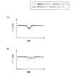
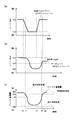
- FIGS. 10A and 11A show the transmission throughput, that is, the temporal variation of the output bit rate 24 of the media data output from the buffer 17 according to the conventional input bit rate control method, and the transmission data. It is a figure which shows the time change of the input bit rate 23 of the data rate, ie, the media data input into the buffer 17.
- FIG. 10A and 11A show the transmission throughput, that is, the temporal variation of the output bit rate 24 of the media data output from the buffer 17 according to the conventional input bit rate control method, and the transmission data. It is a figure which shows the time change of the input bit rate 23 of the data rate, ie, the media data input into the buffer 17.
- FIG. 10B and FIG. 11B show the transmission throughput, that is, the temporal variation of the output bit rate 24 of the media data output from the buffer 17 according to the input bit rate control method of this embodiment, and the transmission.
- FIG. 6 is a diagram showing temporal changes in the data rate of data to be received, that is, the input bit rate 23 of media data input to the buffer 17.
- the value of the input bit rate 23 decreases following the instantaneous decrease in transmission throughput. It is assumed that the time interval for controlling the input bit rate is set short in order to prevent the buffer 17 from overflowing.
- the input bit rate update value for updating the input bit rate 23 is set to the transmission throughput, that is, the output bit rate 24.
- the value is obtained by adding the value of the reduction rate to the value (input bit rate upper limit value). For this reason, in the input bit rate control method according to the present embodiment, the amount of decrease in the input bit rate 24 is smaller than that of the conventional input bit rate control method. It is possible to provide.
- the input bit rate update value for updating the input bit rate 23 is a value obtained by adding the value of the reduction rate to the value of the output bit rate 24 (input bit rate upper limit value). ) Or the value obtained by subtracting the value of the increase rate from the value of the output bit rate 24 (input bit rate lower limit value).
- the input bit rate 23 changes both when the input bit rate 23 is decreased and when the input bit rate 23 is increased as compared with the conventional input bit rate control method. For example, it is possible to reduce the visual discomfort given to the viewer.
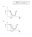
- the value of the input bit rate 23 decreases as the transmission throughput decreases as shown in FIG. It is assumed that the time interval for controlling the input bit rate is set short in order to prevent the buffer 17 from overflowing.
- the input bit rate control method of the present embodiment As shown in FIG. 11B, the input bit rate is moderately lowered as compared with the conventional input bit rate control method. Therefore, for example, it is possible to reduce the visual discomfort given to the viewer.
- the control of the input bit rate according to the present embodiment is performed with respect to the time TA (see FIG. 11A) in the conventional input bit rate control method.
- the time TB in the method (see FIG. 11B) is long.
- the input bit rate control method according to the present embodiment gradually reduces the image quality over time as compared with the conventional input bit rate control method. It is possible to reduce a sense of incongruity.
- the AV device 2 on the server side calculates the input bit rate update value, and converts the bit rate (data rate) of the media data input to the buffer 17 according to the calculated input bit rate update value.
- the relay apparatus connected to the server-side AV device 2 calculates the input bit rate update value, and the bit rate (data rate) of the media data input to the buffer 17 Is converted in accordance with the calculated input bit rate update value.
- FIG. 12 is a network configuration diagram of the present embodiment.
- the network 100 includes AV devices 101 and 102 and relay devices 103 and 104.
- the AV device 101 is a server-side AV device that transmits media data. Unlike the server-side AV device 2 of the first embodiment, the AV device 101 does not control the input bit rate.
- the AV device 102 is a client-side AV device that receives media data transmitted from another device and reproduces and displays the received media data.
- the AV device 101 is, for example, an HDD recorder device or a Blu-ray Disk (registered trademark) recorder device capable of storing video content data having a communication function.
- the AV device 102 is a display device such as a television having a communication function.
- the relay device 103 and the relay device 104 are devices that relay communication, such as gateways, routers, bridges, and switching hubs.
- the relay apparatus 103 controls the input bit rate.
- the relay apparatus 103 and the relay apparatus 104 will be described as a wired-wireless bridge.
- communication between the AV device 101 and the relay device 103 and communication between the AV device 102 and the relay device 104 are realized by wired communication, and the communication between the relay device 103 and the relay device 104 is performed.
- Communication is realized by wireless communication.
- the AV device 101 performs streaming distribution of the stored video content data.
- the AV device 102 receives the streaming content video content data via the relay device 103 and the relay device 104, and plays back and displays the received video content data.
- the viewer can view the video content data stored in the AV device 101 on the AV device 102.
- a general AV device can be used for the AV devices 101 and 102, and a general relay device can be used for the relay device 104 connected to the client side, and detailed description thereof is omitted.
- FIG. 13 is a device configuration diagram of the relay device 103 connected to the server-side AV device 101 of FIG. 12.
- the relay device 103 includes a code conversion unit 12, a memory 13 storing an input bit rate control program 16, and CPU 14, communication I / F unit 15 including buffer 17, and communication I / F unit 111.
- the relay device 103 is connected to the relay device 104 by the communication I / F unit 15 and is connected to the AV device 101 by the communication I / F unit 111.
- the communication I / F unit 111 has a function of transmitting / receiving data via a network, for example, a function of performing modulation / demodulation of a data signal and media access control, and is a communication I / F unit for wired communication here.
- the communication I / F unit 111 receives media data recorded in the AV device 101 from the AV device 101.
- the CPU 14 executes the input bit rate control program 16 stored in the memory 13 to calculate an input bit rate update value (see FIGS. 6 and 7), and the code conversion unit 12 follows the calculated input bit rate update value.
- the bit rate (data rate) of received media data is converted.
- the communication I / F unit 15 transmits the media data obtained by the conversion by the code conversion unit 12 to the relay device 104 via the network while temporarily storing it in the buffer 17.
- the relay device 104 sends the received media data to the AV device 102 on the client side.
- the AV device 2 on the server side calculates the input bit rate update value, and converts the bit rate (data rate) of the media data input to the buffer 17 according to the calculated input bit rate update value.
- the client-side AV device calculates the data rate update value used for conversion of the bit rate (data rate) of the media data performed by the server-side AV device. The updated data rate value is fed back to the AV device on the server side, and the AV device on the server side converts the bit rate (data rate) of the media data according to the data rate update value fed back from the AV device on the client side.
- FIG. 14 is a network configuration diagram of the present embodiment, and the network 500 includes AV devices 501 and 502.
- the AV device 501 is a server-side AV device that stores and holds media data and transmits media data.
- the AV device 502 receives and receives media data transmitted from other devices. It is an AV device on the client side that reproduces and displays the media data.
- the AV device 501 is, for example, an HDD recorder device or a Blu-ray Disk (registered trademark) recorder device that can store video content data having a communication function.
- the AV device 3 is a display device such as a television having a communication function. Examples of the communication function include those listed in the first embodiment. In FIG. 14, the communication function is represented by wireless communication.
- the AV device 501 performs streaming distribution of the stored video content data, for example, and the AV device 502 receives the streaming content video content data, and reproduces and displays the received video content data.
- the viewer can view the video of the video content data stored in the AV device 501 with the AV device 502.
- ⁇ Device configuration of AV equipment (server side)> 15 is a device configuration diagram of the server-side AV device 501 of FIG. 14.
- the AV device 501 includes a media data storage unit 11, a code conversion unit 12, a memory 511, a CPU 512, and a communication I / F unit 513. With.
- the memory 511 is constructed by a semiconductor memory such as a ROM or a RAM, for example.
- the memory 511 stores and holds programs such as various control programs and various applications. For example, the data rate information transmitted from the client-side AV device 502 is analyzed, and the data rate update value included therein is converted into a code conversion unit. 12, a program (hereinafter referred to as “data rate changing program”) 514 for notifying the terminal 12 is stored.
- the memory 511 has an area used when the CPU 512 operates.
- the CPU 512 has a function of performing various controls and various calculations of the entire AV device 501 by reading a program stored in the memory 511 and executing the read program. For example, the CPU 512 reads the data rate change program 514 from the memory 511 and executes the read data rate change program 514. This process will be described later with reference to FIGS.
- the communication I / F unit 513 has a function of transmitting and receiving data via a network, for example, a function of performing modulation / demodulation of data signals and media access control.
- a communication I / F unit for wireless communication is a communication I / F unit for wireless communication.
- the communication I / F unit 513 has a transmission buffer (not shown).
- FIG. 16 is a functional block diagram of the CPU 512 of FIG. However, FIG. 16 also illustrates other components of the AV device 501 in order to facilitate understanding of the functional configuration of the CPU 512.
- the CPU 512 reads out the data rate changing program 514 stored in the memory 511 and executes the read data rate changing program 514. As a result, the CPU 512 functions as the rate information reception analysis unit 531.
- the rate information reception analysis unit 531 receives the data rate information transmitted from the AV device 502 on the client side via the communication I / F unit 513, analyzes the received data rate information, and includes the data rate update value therein Set to the updated data rate value.
- the rate information reception analysis unit 531 converts the data rate update value to the code conversion unit 12 without changing the data rate update value when the data rate update value is equal to or less than the value of the maximum data rate that can be set for the media data to be transmitted.
- the rate information reception analysis unit 531 resets the data rate update value to the maximum data rate value, The code conversion unit 12 is notified of the set data rate update value.
- the code conversion unit 12 converts the bit rate (data rate) of the media data stored in the media data storage unit 11 in accordance with the data rate update value notified from the rate information reception analysis unit 531 and is obtained by the conversion.
- the media data is output to a buffer (not shown) in the communication I / F unit 513.
- FIG. 17 is a flowchart showing the flow of the data rate changing process performed by the CPU 512 of FIG.
- the CPU 512 reads the data rate change program 514 stored in the memory 511 and executes the read data rate change program 514, thereby executing the processing of the flowchart of FIG.
- the rate information reception analysis unit 531 of the CPU 512 determines whether data rate information has been received from the AV device 502 on the client side via the communication I / F unit 513 (step S301).
- the rate information reception analysis unit 531 repeats the process of step S301 while determining that the data rate information has not been received (S301: NO).
- the rate information reception analysis unit 531 analyzes the received data rate information and sets the data rate update value to the data rate update value included therein (step S302). ).
- the rate information reception analysis unit 531 determines whether or not the data rate update value set in step S302 (the data rate update value included in the received data rate information) is greater than the maximum data rate value that can be set for the media data to be transmitted. Is determined (step S303). If the data rate update value set in step S302 is larger than the maximum data rate value (S303: YES), the rate information reception analysis unit 531 resets the data rate update value to the maximum data rate value (step S304). ), The data rate update value reset in step S304 is notified to the code converter 12 (step S305).
- the rate information reception analysis unit 531 uses the data rate update value set in step S302 as the code conversion unit 12. (Step S305). After step S305 is performed, the process returns to step S301.
- the code conversion unit 12 converts the bit rate (data rate) of the media data stored in the media data storage unit 11 according to the data rate update value notified from the rate information reception analysis unit 531 and is obtained by the conversion.
- Media data is output to a buffer (not shown) in the communication I / F unit 513.
- the communication I / F unit 513 transmits media data stored in a buffer (not shown) to, for example, the AV device 502 on the client side via the network.
- ⁇ Device configuration of AV equipment (client side)> 18 is a device configuration diagram of the client-side AV device 502 of FIG. 14.
- the AV device 502 includes a memory 551, a CPU 552, and a communication I / F unit 553.
- the memory 551 is constructed by a semiconductor memory such as a ROM or a RAM, for example.
- the memory 551 stores and holds programs such as various control programs and various application programs.
- the code conversion unit 12 (see FIG. 15) of the AV device 501 on the server side sets the bit rate (data rate) of media data.
- a data rate update value used for conversion is determined, and a program (hereinafter referred to as “data rate calculation program”) 554 for notifying the determined data rate update value to the AV device 501 on the server side is stored and held. is doing.
- the memory 551 has an area used when the buffer 555 for temporarily storing and holding the media data received by the communication I / F unit 553 and the CPU 552 operate.
- the buffer 555 will be described later with reference to FIG.
- the CPU 552 has a function of performing various controls and various calculations of the entire AV device 502 by reading a program stored in the memory 551 and executing the read program. For example, the CPU 552 reads the data rate calculation program 554 from the memory 551 and executes the read data rate calculation program 554. This process will be described later with reference to FIGS.
- the communication I / F unit 553 has a function of transmitting / receiving data via a network, for example, a function of performing modulation / demodulation of a data signal and media access control, and is a wireless communication I / F unit here.
- FIG. 19 is a diagram for explaining a configuration example of the buffer 555 of FIG.
- the accumulation amount 561 represents the data amount of data accumulated in the buffer 555
- the buffer free space 562 represents the data amount of remaining data that can be accumulated in the buffer 555.
- the unit of the data amount can be expressed by bits or bytes or the like for both the accumulation amount 561 and the buffer free space 562, and this embodiment will be described using bits.
- the input bit rate 563 represents the data amount per unit time of the media data input to the buffer 555
- the output bit rate 564 represents the data amount per unit time of the media data output from the buffer 555.
- bps bit per second
- the input bit rate 563 is equal to the transmission throughput when the communication I / F unit 553 receives media data
- the output bit rate 564 is output from the code conversion unit 12 of the AV device 502 on the server side (see FIG. 15). It is assumed that it is equal to the bit rate (data rate) of the media data to be processed.
- Buffer 555 outputs the input media data in the input order in accordance with the FIFO operation principle. At this time, when the input bit rate 563 and the output bit rate 564 are equal, the accumulation amount 561 of the buffer 555 does not change. When the input bit rate 563 and the output bit rate 564 are not equal, the accumulation amount 561 of the buffer 555 increases or decreases according to the difference between the input bit rate 563 and the output bit rate 564. That is, when the input bit rate 563 is larger than the output bit rate 564, the accumulation amount 561 of the buffer 555 increases, and when the input bit rate 563 is smaller than the output bit rate 564, the accumulation amount 561 of the buffer 555 decreases.
- the storage amount 561 of the buffer 555 increases at a speed of 4 Mbps, in other words, the buffer free capacity 562 of the buffer 555 decreases at a speed of 4 Mbps.
- the input bit rate 563 is 6 Mbps and the output bit rate 564 is 9 Mbps
- the accumulated amount 561 of the buffer 555 decreases at a speed of 3 Mbps, in other words, the buffer free capacity 562 of the buffer 555 increases at a speed of 3 Mbps.
- the buffer 555 temporarily holds media data until the media data is reproduced.
- the accumulation amount 561 of the buffer 555 becomes zero, that is, when a buffer underflow occurs, there is no data to be reproduced, and thus video and audio are interrupted.
- the AV device 502 on the client side starts the reproduction of media data after the accumulated amount 561 of the buffer 555 exceeds a certain amount.
- FIG. 20 is a functional block diagram of the CPU 552 of FIG. However, FIG. 20 also shows other components of the AV device 502 in order to facilitate understanding of the functional configuration of the CPU 552.
- the CPU 552 reads the data rate calculation program 554 stored and held in the memory 551 and executes the read data rate calculation program 554.
- the CPU 552 functions as a transmission throughput detection unit 571, a buffer accumulation amount detection unit 572, a decrease rate / increase rate calculation unit 573, a data rate calculation unit 574, a data rate determination unit 575, and a data rate information transmission control unit 576. To do.
- the transmission throughput detecting unit 571 detects the value of the input bit rate 563 of the media data input to the buffer 555, that is, the value of the transmission throughput, and the detected value of the input bit rate 563, that is, the value of the transmission throughput, is the data rate calculating unit 574. Output to.
- FIG. 21 is a functional block diagram of the transmission throughput detector 571 of FIG. FIG. 21 also shows the memory 551 and the data rate calculation unit 574 in order to clarify the connection relationship between the internal elements of the transmission throughput detection unit 571 and the memory 551 and the data rate calculation unit 574.
- the transmission throughput detection unit 571 functions as a data rate detection unit 591, a buffer change rate calculation unit 592, and a transmission throughput calculation unit 593.
- the data rate detection unit 591 detects the data amount per unit time of the media data output from the buffer 555, and the detection result is the value of the output bit rate 564 of the media data output from the buffer 555, that is, the data rate of the media data. Is output to the transmission throughput calculation unit 593.
- the buffer change rate calculating unit 592 calculates an increase or decrease in the accumulated amount 561 per unit time as the change rate, and outputs the calculated change rate value to the transmission throughput calculating unit 593. To do. However, the rate of change when the accumulated amount 561 increases is represented by a positive value, and the rate of change when the accumulated amount 561 decreases is represented by a negative value.
- the transmission throughput calculation unit 593 subtracts the change rate value input from the buffer change rate calculation unit 592 from the value of the output bit rate 564 input from the data rate detection unit 591, that is, the data rate value.
- the buffer accumulation amount detection unit 572 detects the value of the accumulation amount 561 of the buffer 555 and outputs the detected value of the accumulation amount 561 to the decrease rate / increase rate calculation unit 573.
- the decrease rate / increase rate calculation unit 573 uses the accumulation amount 561 of the buffer 555 input from the buffer accumulation amount detection unit 572, and the allowable decrease rate value and the increase rate value of the accumulation amount 561 of the buffer 555. And the calculated decrease rate value and increase rate value are output to the data rate calculation unit 574.
- the decrease rate / increase rate calculation unit 573 calculates the increase rate as follows.
- the increase rate setting value is the maximum value of the accumulation amount 561 of the target buffer 555 after the secured time by adjusting the increase / decrease of the accumulation amount 561 of the buffer 555 by controlling the output bit rate 564, that is, the data rate.
- the increase rate set value is mainly used when performing control to increase the output bit rate 564, that is, the data rate.
- the calculated increase rate value is an increase rate of the accumulated amount 561 of the buffer 555 per unit time required to increase the accumulated amount 561 of the buffer 555 to the increase rate set value after the securing time. .
- the decrease rate / increase rate calculation unit 573 calculates the decrease rate as follows.
- the decrease rate set value is the minimum value of the target accumulation amount 561 of the buffer 555 after the secured time by adjusting the increase / decrease of the accumulation amount 561 of the buffer 555 by controlling the output bit rate 564, that is, the data rate.
- the decrease rate setting value is mainly used when the output bit rate 564, that is, the control for reducing the data rate is performed.
- the calculated decrease rate value is the decrease rate of the accumulated amount 561 of the buffer 555 per unit time required when the accumulated amount 561 of the buffer 555 is reduced to the decrease rate set value after the securing time. .
- the increase rate set value is larger than the decrease rate set value.
- the increase rate setting value can be set to an arbitrary value at the time of design.
- the increase rate setting value may be the maximum accumulation amount of the buffer 555.
- the reduction rate setting value can be set to an arbitrary value at the time of design, for example, the reduction rate setting value may be set to zero.
- the securing time used for calculating the increase rate and the decrease rate can be set to an arbitrary value at the time of design, but can be set as, for example, the duration of a transmission path error that occurs continuously.
- the securing time used for calculating the increase rate and the securing time used for calculating the decrease rate may be the same value or different values.
- data rate upper limit value is an upper limit value of the data rate that is allowed when the data rate update value is set.
- the data rate calculation unit 574 subtracts the value of the increase rate input from the decrease rate / increase rate calculation unit 573 from the value of the input bit rate 563 input from the transmission throughput detection unit 571, that is, the value of the transmission throughput,
- the data rate lower limit value is a lower limit value of the data rate that is allowed when the data rate update value is set.
- the data rate determining unit 575 is based on the current data rate value detected by the data rate detecting unit 591 in FIG. 21 and the data rate upper limit value and data rate lower limit value input from the data rate calculating unit 574.
- the data rate update value is determined, and the determined data rate update value is output to the data rate information transmission control unit 576.
- the data rate determining unit 575 sets the data rate update value to the current data rate value.
- the data rate determining unit 575 sets the data rate update value to the data rate lower limit value if the current data rate value is smaller than the data rate lower limit value, and if the current data rate value is larger than the data rate upper limit value, Set the data rate update value to the upper limit of the data rate.
- Data rate information transmission control section 576 outputs data rate information including the data rate update value input from data rate determination section 575 to communication I / F section 553.
- the data rate information is transmitted from the communication I / F unit 553 to the AV device 501 on the server side, for example.
- the configuration of the CPU 552 described with reference to FIGS. 20 and 21 only by detecting the state of the buffer 555 such as the accumulation amount 561 of the buffer 555, the output bit rate 564, and the rate of change of the accumulation amount 561 of the buffer 555, The conversion of the data rate of the media data by the code conversion unit 12 of the AV device 501 on the server side can be controlled. For this reason, control of data rate conversion is facilitated, and the configuration of the AV device 502 can be simplified.
- FIG. 22 is a flowchart showing the flow of data rate calculation processing performed by the CPU 552 of FIG. However, the CPU 552 reads the data rate calculation program 554 stored in the memory 551 and executes the read data rate calculation program 554, thereby executing the processing of the flowchart of FIG.
- the CPU 552 determines whether the value of the accumulation amount 561 of the buffer 555 is smaller than a preset control start threshold (step S501).
- step S501 While the value of the accumulation amount 561 of the buffer 555 is equal to or greater than the control start threshold (S501: NO), the process of step S501 is repeatedly performed, and the data rate calculation process is not performed. For example, it is determined that the transmission throughput is stable until the value of the accumulation amount 561 becomes smaller than the control start threshold, and the data rate is not updated. Further, it is determined that the transmission throughput is stable until the value of the accumulation amount 561 becomes equal to or greater than the control start threshold value after the transmission path state is recovered until the value of the accumulation amount 561 becomes smaller than the control start threshold value again.
- the data rate value is fixed at the data rate value when the accumulated amount 561 is equal to or greater than the control start threshold value.
- the control start threshold value when the value of the accumulation amount 561 of the buffer 555 is equal to or greater than the control start threshold value, it is determined that the transmission throughput is stable, and the accumulation amount 561 of the buffer 555 is instantaneous when the transmission throughput is stable.
- the data rate is not updated for any fluctuations. For this reason, the data rate is kept constant when the transmission throughput is stable.
- the transmission throughput when the transmission throughput is stable, there is no change in the resolution of the video reproduced by the AV device 3 on the client side or the frame rate is lowered, and the viewer feels uncomfortable. You can watch the video without
- the CPU 552 executes the data rate update value determination process whose process flow is shown in FIG. A rate update value is determined (step S502).
- the data rate information transmission control unit 576 of the CPU 552 outputs data rate information including the data rate update value determined in the process of step S502 to the communication I / F unit 553 (step S503), and the process of step S501 is performed.
- the communication I / F unit 553 transmits the data rate information input from the data rate information transmission control unit 576 to, for example, the server-side AV device 501 via the network.
- FIG. 23 is a flowchart showing the flow of the data rate update value determination process (step S502) of FIG.
- the data rate detection unit 591 detects the value of the output bit rate 594 of the media data output from the buffer 555, that is, the value of the data rate of the media data, and the buffer change rate calculation unit 592 A change rate value of the accumulation amount 561 is calculated. Then, the transmission throughput calculation unit 593 calculates the value of the input bit rate 563, that is, the value of the transmission throughput by subtracting the value of the calculated change rate from the value of the detected output bit rate 564, that is, the data rate. Step S601).
- the buffer accumulation amount detection unit 572 detects the value of the accumulation amount 561 of the buffer 555 (step S602).
- the decrease rate / increase rate calculation unit 573 calculates the value of the increase rate by subtracting the accumulated amount 561 of the buffer 555 detected in step S602 from the increase rate set value and dividing the subtracted value by the reserved time. (Step S603). Further, the decrease rate / increase rate calculation unit 573 subtracts the decrease rate set value from the value of the accumulation amount 561 of the buffer 555 detected in step S602, and divides the subtraction value by the reserved time, thereby obtaining the value of the decrease rate. Is calculated (step S604).
- the data rate calculation unit 574 adds the value of the decrease rate calculated in step S604 to the transmission throughput value detected in step S601, and sets the added value as the data rate upper limit value (step S605). Further, the data rate calculation unit 574 subtracts the increase rate value calculated in step S603 from the transmission throughput value detected in step S601, and sets the subtraction value as the data rate lower limit value (step S606).
- the data rate determination unit 575 determines whether the current data rate value is within the range of the data rate lower limit value obtained in step S606 and less than or equal to the data rate upper limit value obtained in step S605 (step S607).
- the data rate determining unit 575 sets the data rate update value to the current data rate value (step S608), and step S503 in FIG. Is done.
- the current data rate value is in the range between the data rate lower limit value and the data rate upper limit value. If it is within, the data rate is not updated. For this reason, if the value of the current data rate is within the above range, the data rate is stable without changing even if the transmission throughput changes. As a result, for example, it is possible to avoid a situation in which the resolution or frame rate of the video played back by the AV device 502 on the client side suddenly increases or decreases, and the viewer can view videos of stable quality.
- the data rate determining unit 575 determines whether the current data rate value is larger than the data rate upper limit value (step S609).
- the accumulated amount 561 of the buffer 555 is reduced and the data rate upper limit value is lower than the current data rate value.
- the data rate determining unit 575 sets the data rate update value to the data rate upper limit value in order to lower the data rate (step S610), and the process of step S503 in FIG. 22 is performed.
- step S609 NO
- the data rate determining unit 575 sets the data rate update value to the data rate lower limit value in order to increase the data rate (step S611). The process of step S503 in FIG. 22 is performed.
- FIG. 24 is a sequence diagram when a data stream is distributed from the server-side AV device 501 to the client-side AV device 502.
- the code conversion unit 12 converts the bit rate (data rate) of the video data stored in the media data storage unit 11, and the video data obtained by this conversion is converted into the communication I / F unit. Streamed via 513.
- the AV device 502 on the client side receives the streamed video data by the communication I / F unit 553, and sequentially plays back the received video data while accumulating it in the buffer 555 of the memory 551 (step S701).
- the CPU 552 reads the data rate calculation program 554 from the memory 551 and executes it (see FIGS. 22 and 23), thereby calculating the data rate update value (step S702).
- the data rate information including the updated data rate value is transmitted to the AV device 501 via the communication I / F unit 553 (step S703).
- the CPU 512 reads the data rate change program 514 from the memory 511 and executes it (see FIG. 17), thereby using the data rate update value and the maximum data rate value included in the data rate information.
- the data rate update value is determined (step S704).
- the code conversion unit 12 converts the bit rate (data rate) of the video data stored in the media data storage unit 11 according to the determined data rate update value (step S705).
- Video data obtained by the conversion by the code conversion unit 12 is stream-distributed via the communication I / F unit 513.
- the AV device 502 on the client side receives the video data distributed in the stream by the communication I / F unit 553, and sequentially reproduces the received video data while accumulating it in the buffer 555 of the memory 551 (step S706).
- Example of data rate control> As an example of the control of the output bit rate 564, that is, the data rate, the control of the output bit rate of the media data that is output from the buffer 555, that is, the data rate of the media data in the situation where the transmission throughput is reduced and the transmission throughput is recovered after a certain time. This will be described with reference to FIGS. 25 and 26.
- FIG. 25 and 26 This will be described with reference to FIGS. 25 and 26.
- FIG. 25A and FIG. 26A are diagrams showing temporal variations in transmission throughput, that is, the input bit rate 563 of media data input to the buffer 555, where the vertical axis indicates the rate (bps) and the horizontal axis Represents time. 25 (a) and 26 (a), the transmission path state deteriorates at time t0 and the transmission throughput starts to drop sharply, and the transmission path state recovers at time t3 after a certain period of time for transmission. It shows how the throughput is starting to rise sharply.
- FIG. 25B and FIG. 26B are diagrams showing temporal fluctuations in the data rate of received media data, that is, the output bit rate 564 of media data output from the buffer 555, and the vertical axis indicates the rate. (Bps), the horizontal axis represents time.
- FIG. 25 (c) and FIG. 26 (c) are diagrams showing temporal fluctuations of the accumulation amount 561 of the buffer 555, where the vertical axis represents the buffer accumulation amount and the horizontal axis represents time.
- the transmission path condition deteriorates and the transmission throughput, that is, the input bit rate 563 of the media data input to the buffer 555 starts to decrease, and the value of the input bit rate 563 decreases from tpa to tpb.
- the accumulation amount 561 of the buffer 555 decreases. Since the value of the accumulation amount 561 of the buffer 555 is equal to or greater than the control start threshold value dth until time t1, the value of the output bit rate 564, that is, the value of the data rate remains unchanged (see step S501 in FIG. 22). As described above, while the value of the accumulation amount 561 is equal to or greater than the control start threshold dth, the value of the output bit rate 564, that is, the value of the data rate does not decrease even if the transmission throughput value decreases.
- the value of the accumulation amount 561 of the buffer 555 decreases according to the difference between the value of the input bit rate 563 and the value of the output bit rate 564, and the value of the accumulation amount 561 of the buffer 555 falls below the control start threshold value dth at time t1.
- the CPU 552 starts the determination of the data rate update value and the transmission of the data rate information including the determined data rate update value to the server-side AV device 501 until the value of the accumulation amount 561 in the buffer 555 becomes equal to or greater than the control start threshold value dth. Then, the data rate update value is determined, and data rate information including the determined data rate update value is transmitted to the AV device 501 on the server side (see FIG. 22).
- the transmission throughput detection unit 571 of the CPU 552 detects the value of the input bit rate 563, that is, the value of the transmission throughput, and the buffer accumulation amount detection unit 572 detects the value of the accumulation amount 561 of the buffer 555, and the decrease rate / increase rate calculation unit 573. Calculates an increase rate value and a decrease rate value, and the data rate calculation unit 574 calculates a data rate upper limit value and a data rate lower limit value (see steps S601 to S606 in FIG. 23).
- the data rate determining unit 575 sets the current data rate value to be larger than the data rate upper limit value, sets the data rate update value to the data rate upper limit value, and the data rate information transmission control unit 576 sets the data rate update value.
- the reduction rate setting value is ddw
- the securing time is ta
- the accumulated amount 561 of the buffer 555 at time t2 is d2
- the input bit rate 563 at time t2 that is, the transmission throughput is tpb.
- tpd2 (d2-ddw) / ta.
- the upper limit of the data rate at time t2 is an addition value tpb + tpd2 obtained by adding the value of the subtraction rate (tpd2) at time t2 to the transmission throughput value (tpb) at time t2.
- the transmission throughput is recovered from the state in which the transmission throughput is lowered due to the deterioration of the transmission path state, along with the recovery of the transmission path state.
- the transmission throughput detection unit 571 of the CPU 552 detects the value of the input bit rate 563, that is, the value of the transmission throughput, and the buffer accumulation amount detection unit 572 detects the value of the accumulation amount 561 of the buffer 555, and the decrease rate / increase rate calculation unit 573. Calculates an increase rate value and a decrease rate value, and the data rate calculation unit 574 calculates a data rate upper limit value and a data rate lower limit value (see steps S601 to S606 in FIG. 23).
- the data rate determining unit 575 sets the current data rate value to be smaller than the data rate lower limit value, sets the data rate update value to the data rate lower limit value, and the data rate information transmission control unit 576 sets the data rate update value.
- Is output to the communication I / F unit 553 see steps S607, S609, S610 in FIG. 23, and step S503 in FIG. 22). As a result, the data rate value gradually increases with a smaller value than the transmission throughput value.
- the increase rate setting value is dup
- the securing time is ta
- the accumulated amount 561 of the buffer 555 at time t4 is d4
- the transmission throughput at time t4 that is, the input bit rate 563 is tpa.
- tpu4 (dup ⁇ d4) / ta.
- the lower limit of the data rate at time t4 is a subtraction value tpa-tpu4 obtained by subtracting the increase rate value (tpu4) at time t4 from the transmission throughput value (tpa) at time t4.
- tp4 tpa ⁇ tpu4.
- the storage amount 561 of the buffer 555 starts to increase.
- the value of the media data output bit rate 564 output from the buffer 555 that is, the data rate of the media data is fixed (See step S501 in FIG. 22).
- the output bit rate 564 that is, the data rate control is performed so that the output bit rate 564 of the media data output from the buffer 555 decreases in order to prevent the underflow of the buffer 555. Is done.
- the output bit rate 564 that is, the data rate is not lowered so that the value of the output bit rate 564 becomes the value of the input bit rate 563, but the accumulated amount 561 of the buffer 555 is used to output the output bit rate.
- the value of the output bit rate 564 that is, the value of the data rate is lowered so that the value of the rate 564 is larger than the value of the input bit rate 563.
- a reduction rate value is calculated such that the value of the accumulation amount 561 of the buffer 555 becomes the reduction rate set value after the above-described securing time, and the current data rate value is calculated as the reduction rate value and the transmission throughput.
- the data rate is controlled so that the data rate value becomes the data rate upper limit value if it is larger than the value added to the value (data rate upper limit value).
- the value of the accumulated amount 561 of the buffer 555 increases or decreases in accordance with the difference between the value of the input bit rate 563 and the value of the output bit rate 564, so that the value of the output bit rate 563, that is, the value of the data rate is the upper limit of the data rate.
- the accumulated amount 561 of the buffer 555 decreases according to the decrease rate even when the transmission throughput does not change.
- the control method for reducing the data rate when the transmission throughput is reduced when the value of the accumulation amount 561 of the buffer 555 is large, the value of the subtraction rate to be added to the value of the transmission throughput increases, and the upper limit of the data rate The value increases. For this reason, when the transmission throughput is temporarily reduced, the data rate is compared with the case where the output bit rate 564, that is, the data rate is reduced so that the value of the output bit rate 564 becomes the value of the input bit rate 563. The amount of decrease is smaller, and the temporal variation of the data rate can be further reduced. As a result, for example, when the transmission throughput temporarily decreases during the distribution of the video data, it is possible to reduce the amount of reduction in the resolution and frame rate of the video reproduced on the receiving side, and the viewer can achieve stable quality. You can watch the video.
- the value of the accumulation amount 561 of the buffer 555 when the value of the accumulation amount 561 of the buffer 555 is small, the value of the reduction rate added to the transmission throughput value is small, but the input bit is within a range where the value of the accumulation amount 561 of the buffer 555 does not fall below the reduction rate set value. Reduce the difference between the rate value and the output bit rate value. For this reason, even if the value of the accumulated amount 561 of the buffer 555 becomes smaller due to the decrease in the transmission throughput for a certain period, the value of the accumulated amount 561 of the buffer 555 becomes smaller than the reduction rate set value, and the buffer 555 Underflow does not occur. Thus, for example, even if the transmission throughput continues to decrease for a certain period during the transmission of the video data, the video is not interrupted due to the underflow of the buffer 555, and the viewer can view the video without interruption.
- the decrease rate of the accumulation amount 561 of the buffer 555 gradually increases as the value of the accumulation amount 561 of the buffer 555 becomes smaller. Therefore, the data rate value can be gradually reduced. As a result, for example, when the transmission throughput is reduced during transmission of video data, the resolution and frame rate of the video reproduced on the receiving side can be lowered gradually, and the uncomfortable feeling felt by the viewer can be reduced.
- the reduction rate setting value By setting the reduction rate setting value to zero, the value of the reduction rate of the accumulation amount 561 when the value of the accumulation amount 561 of the buffer 555 becomes the reduction rate setting value after the securing time can be maximized. it can. For this reason, the amount of decrease in the value of the data rate can be minimized as compared with the case where the decrease rate setting value is set to a value larger than zero.
- the output bit rate of the media data output from the buffer 555 to provide the viewer with a high-quality video is controlled so that 564 increases.
- the output bit rate 564 that is, the data rate is not increased so that the value of the output bit rate 564 becomes the value of the input bit rate 563, but the accumulated amount 561 of the buffer 555 is used to output the output bit rate.
- the value of the output bit rate 564 that is, the value of the data rate is increased so that the value of the rate 564, that is, the value of the data rate is smaller than the value of the input bit rate 563.
- an increase rate value is calculated such that the value of the accumulated amount 561 of the buffer 555 becomes the increase rate set value after the above securing time, and the current data rate value is calculated from the transmission throughput value.
- the data rate is controlled so that the data rate value becomes the data rate lower limit value.
- the value of the accumulation amount 561 of the buffer 555 increases or decreases in accordance with the difference between the value of the input bit rate 563 and the value of the output bit rate 564, so that the value of the output bit rate 563, that is, the value of the data rate is the lower limit of the data rate.
- the accumulated amount 561 of the buffer 555 increases according to the increase rate even when the transmission throughput does not change.
- the increase rate of 561 gradually decreases as the value of the accumulation amount 561 of the buffer 555 increases. For this reason, the value of the data rate can be increased gradually.
- the resolution and frame rate of the video reproduced on the receiving side can be gradually increased, and the uncomfortable feeling felt by the viewer can be reduced.
- the increase rate setting value as the maximum accumulation amount of the buffer 555, the value of the accumulation amount 561 of the buffer 555 when the state where the transmission throughput is recovered can be maximized. Can be used most effectively.
- the transmission throughput at each time point varies finely. Therefore, if the transmission throughput value, that is, the input bit rate 563 increases, the data rate value, that is, the output bit rate 564 increases, and if the transmission throughput value, that is, the input bit rate 563 decreases, the data rate. When the value of the output bit rate 564 is decreased, it is expected that frequent switching between the control for reducing the data rate and the control for increasing the data rate occurs.
- the data rate value is always the transmission throughput value.
- the value is switched to a control state in which the data is reduced to be a value obtained by adding the value of the reduction rate of the accumulation amount 671 of the buffer 555 to the value, the data rate value is changed from the transmission throughput value to the accumulation amount 671 of the buffer 555.
- the value obtained by subtracting the value of the increase rate is changed to a value obtained by adding the value of the decrease rate of the accumulated amount 671 of the buffer 555 to the value of the transmission throughput.
- the value of the data rate increases by a value obtained by adding the value of the increase rate and the value of the decrease rate, and increases rapidly. For this reason, when the transmission throughput is lowered, for example, the resolution and frame rate of the video reproduced by the AV device 502 on the client side are rapidly increased.
- the value of the transmission throughput is determined. Further, the current data rate value is maintained while the addition value (data rate upper limit value) obtained by adding the decrease rate value of the accumulation amount 561 of the buffer 555 is larger than the current data rate value.
- the data rate update value is set as the data rate upper limit value. If the current data rate value is less than or equal to the data rate upper limit value, the data rate update value is The data rate value of.
- the data rate value is always transmitted from the control state in which the data is lowered such that the data rate value is always the value obtained by adding the reduction rate value of the accumulated amount 671 of the buffer 555 to the transmission throughput value.
- the data rate value is accumulated in the buffer 555.
- a value obtained by adding the decrease rate value of the amount 671 is changed to a value obtained by subtracting the increase rate value of the accumulated amount 671 of the buffer 555 from the transmission throughput value.
- the value of the data rate decreases by the value obtained by adding the value of the increase rate and the value of the decrease rate, and rapidly decreases. For this reason, when the transmission throughput is restored, for example, the resolution and the frame rate of the video reproduced by the AV device 3 on the client side are drastically lowered.
- the value of the transmission throughput is obtained.
- the current data rate value is maintained while the subtraction value (data rate lower limit value) obtained by subtracting the increase rate value of the accumulated amount 561 of the buffer 555 from the current data rate value is smaller than the current data rate value.
- the data rate update value is used as the data rate lower limit value. If the current data rate value is greater than or equal to the data rate lower limit value, the data rate update value is The data rate value of.
- the present invention is not limited to the contents described in the above embodiment, and can be implemented in any form for achieving the object of the present invention and the object related thereto or incidental thereto. .
- the output bit rate 24 of the media data output from the buffer 17 is detected by using the output bit rate detection unit 31 having the functional configuration shown in FIG.
- the following may be used.
- the number of transmission success frames per unit time is obtained from ACK (Acknowledgement) or NACK (Negative ACK), and the value of transmission throughput is calculated.
- a method of using the calculated transmission throughput value as the output bit rate value may be used. The following can be considered as an example of measuring the transmission throughput from the actual communication state.
- the input bit rate 23 is controlled using the actually measured transmission throughput value.
- the input bit rate 23 can be controlled more reliably than when the output bit rate 24 is calculated from the input bit rate 23 of the input media data and the rate of change of the buffer free capacity 22 of the buffer 17.
- transmission throughput is detected using the transmission throughput detection unit 571 having the functional configuration shown in FIG. 21.
- the present invention is not limited to this, and the following may be used, for example. .
- a method of calculating the transmission throughput by obtaining the number of successfully received frames per unit time using CRC (Cyclic Redundancy Check) or FCS (Frame Check Sequence) may be used.
- CRC Cyclic Redundancy Check
- FCS Full Check Sequence
- the server side AV device 501 is compared with the case where the output bit rate 564 is calculated from the change rate of the media data output bit rate 564 output from the buffer 555 and the storage amount 561 of the buffer 555. It is possible to reliably control the conversion of the data rate of the media data performed in the above.
- the input bit rate value is fixed to the current input bit rate value.
- the value of the input bit rate may be fixed to a predetermined value (for example, the value of the maximum data rate that can be set for the media data).
- the data rate value is fixed to the data rate value at that time.
- the data rate value may be fixed to a predetermined value (the maximum data rate value that can be set for the media data).
- the value of the input bit rate is fixed when the transmission throughput increases and the value of the buffer free capacity 22 of the buffer 17 becomes equal to or greater than the control start threshold.
- the value of the input bit rate is fixed when the value of the buffer free space 22 of the buffer 17 becomes equal to or greater than a threshold value set between the control start threshold value and the increase rate setting value, for example. It may be.
- the data rate value is fixed when the transmission throughput recovers and the value of the accumulated amount 561 of the buffer 555 becomes equal to or greater than the control start threshold.
- the present invention is limited to this. Instead, the value of the data rate may be fixed when the value of the accumulation amount 561 of the buffer 555 becomes equal to or greater than the threshold value set between the control start threshold value and the increase rate setting value.
- the wireless communication between the 501 and the AV device 502 is not limited to this, but may be a power line, a telephone line, a coaxial cable, an optical cable, or the like.
- the communication I / F unit 15 of the first and second embodiments and the communication I / F units 513 and 553 of the third embodiment are wireless communication interfaces, but are not limited thereto.
- a communication interface such as Ethernet (registered trademark), USB (Universal Serial Bus), HDMI (registered trademark) (High-Definition Multimedia Interface), IEEE 1394, or the like may be used.
- the current input bit rate value is compared with the input bit rate lower limit value and the input bit rate upper limit value, and the input bit rate update value is set according to the comparison result.
- the present invention is not limited to this. For example, the following may be used. If a decrease in transmission throughput is detected, the current input bit rate value is compared with the input bit rate upper limit value. If the current input bit rate value is greater than the input bit rate upper limit value, the input bit rate is updated. The value may be set to the input bit rate upper limit value, and the input bit rate update value may be set to the current input bit rate value if the current input bit rate value is less than or equal to the input bit rate upper limit value.
- the current input bit rate value is compared with the input bit rate lower limit value. If the current input bit rate value is smaller than the input bit rate lower limit value, the input bit rate The rate update value is set to the input bit rate lower limit value, and if the current input bit rate value is greater than or equal to the input bit rate lower limit value, the input bit rate update value may be set to the current input bit rate value. Good.
- the current output bit rate that is, the data rate value is compared with the data rate lower limit value and the data rate upper limit value, and the data rate update value is set according to the comparison result.
- the current data rate value is compared with the data rate upper limit value. If the current data rate value is greater than the data rate upper limit value, the data rate update value is set to the data rate upper limit value. If the current data rate value is less than or equal to the data rate upper limit value, the data rate update value may be set to the current data rate value.
- the current data rate value is compared with the data rate lower limit value, and if the current data rate value is smaller than the data rate lower limit value, the data rate update value is The rate lower limit value may be set, and if the current data rate value is equal to or greater than the data rate lower limit value, the data rate update value may be set to the current data rate value.
- processing procedure may be replaced if the same contents as the processing of FIG. 7 can be realized.
- processing may be performed in the order of step S204 and step S203
- processing may be performed in the order of step S206 and step S205
- processing may be performed in the order of step S203, step S205, step S204, and step S206. May be.
- processing procedure may be changed as long as the same contents as the processing of FIG. 23 can be realized.
- processing may be performed in the order of step S604 and step S603
- processing may be performed in the order of step S606 and step S605
- further processing may be performed in the order of step S603, step S605, step S604, and step S606. May be.
- the first to third embodiments can be applied to various data such as video data, audio data, video data, and audio data.
- the first to third embodiments can be applied to various transmission devices and reception devices including AV devices and relay devices having a communication function.
- the present invention is not limited to this, and a system buffer is configured in the memory 13. Then, the buffer information may be detected.
- the queue size of the buffer 17 cannot be ensured due to the limitation, the queue size can be increased by adding a system buffer of the memory 13 further. As a result, the buffer size can be easily changed according to the application system to be used. If the buffer size is large, the effect of the method of the first embodiment is further increased.
- the server-side AV device 501 may have a network configuration separated from the relay device as in the second embodiment.
- Each device in each of the above embodiments is not limited to a software configuration that operates by a CPU or MPU, and may be realized by a hardware configuration, for example. In this case, it is typically realized as an LSI (Large Scale Integration) which is an integrated circuit. These may be individually made into one chip, or may be made into one chip so as to include all or part thereof.
- LSI Large Scale Integration
- the name used here is LSI, but it may also be called IC, system LSI, super LSI, or ultra LSI depending on the degree of integration.
- the method of circuit integration is not limited to LSI, and implementation with a dedicated circuit or a general-purpose processor is also possible.
- An FPGA Field Programmable Gate Array
- a reconfigurable processor that can reconfigure the connection and setting of circuit cells inside the LSI may be used.
- integrated circuit technology comes out to replace LSI's as a result of the advancement of semiconductor technology or a derivative other technology, it is naturally also possible to carry out function block integration using this technology. Biotechnology can be applied.
- the present invention can be used to control the data rate of data to be transmitted according to the state of the transmission path.
Landscapes
- Engineering & Computer Science (AREA)
- Computer Networks & Wireless Communication (AREA)
- Signal Processing (AREA)
- Multimedia (AREA)
- Databases & Information Systems (AREA)
- Computer Security & Cryptography (AREA)
- Communication Control (AREA)
- Two-Way Televisions, Distribution Of Moving Picture Or The Like (AREA)
Abstract
Description
以下、本発明の第1の実施の形態について図面を参照しつつ説明する。
図1は本実施の形態のネットワーク構成図であり、ネットワーク1にはAV機器2,3が含まれている。
図2は図1のサーバ側のAV機器2の装置構成図であり、AV機器2は、メディアデータ記憶部11と、符号変換部12と、メモリ13と、CPU(Central Processing Unit)14と、通信インターフェース部(以下、「通信I/F部」と称する。)15とを備える。
図3は図2のバッファ17の一構成例を説明するための図である。
図4は図2のCPU14の機能構成図である。但し、図4には、CPU14の機能構成の理解を容易にするため、AV機器2の他の構成要素も図示している。
図6は図2のCPU14が行う入力ビットレート制御処理の流れを示すフローチャートである。但し、CPU14はメモリ13からそれに記憶されている入力ビットレート制御プログラム16を読み出し、読み出した入力ビットレート制御プログラム16を実行することによって、図6及び後述する図7のフローチャートの処理を実行する。
図7は図6の入力ビットレート更新値決定処理(ステップS102)の流れを示すフローチャートである。
入力ビットレートの制御の一例として、伝送スループットが低下し、一定時間後に伝送スループットが回復する状況におけるバッファ17へ入力されるメディアデータの入力ビットレート即ちメディアデータのデータレートの制御について図8及び図9を参照しつつ説明する。
以下、伝送スループット低下時の入力ビットレートを低下させる制御の一例を図8(a)~図8(c)を参照して説明する。
以下、伝送スループット増大時の入力ビットレートを増大させる制御の一例を図9(a)~図9(c)を参照して説明する。
以下、本実施の形態における入力ビットレートの制御における数値例を示す。但し、初期条件として、最大データレートの値を12Mbps、バッファ17の最大蓄積量を500パケット(以下、「Pkt」と記載する。)、制御開始閾値を450Pkt、増加率設定値を500Pkt、減少率設定値を50Pkt、確保時間を500msecとする。但し、1Pktは1500バイトとする。
現在の入力ビットレート23の値を12Mbpsとし、伝送路状態の悪化により伝送スループットが12Mbpsから6Mbpsに低下し、バッファ17のバッファ空き容量22が制御開始閾値“450Pkt”を下回ったとする。
入力ビットレート上限値=出力ビットレート+減少率=6+9.6=15.6Mbps
CPU14は、増加率及び入力ビットレート下限値を算出する。
入力ビットレート下限値=出力ビットレート-増加率=6-1.2=4.8Mbps
CPU14は、現在の入力ビットレート23の値“12Mbps”が入力ビットレート下限値“4.8Mbps”以上入力ビットレート上限値“15.6Mbps”以下であることから、入力ビットレート更新値を現在の入力ビットレート23の値“12Mbps”とする。さらに、CPU14は、入力ビットレート更新値“12Mbps”が最大データレートの値“12Mbps”より大きくないので、入力ビットレート更新値を12Mbpsのままにする。
入力ビットレート上限値=出力ビットレート+減少率=6+4.8=10.8Mbps
CPU14は、増加率及び入力ビットレート下限値を算出する。
入力ビットレート下限値=出力ビットレート-増加率=6-6=0Mbps
CPU14は、現在の入力ビットレート23の値“12Mbps”が入力ビットレート上限値“10.8Mbps”より大きいことから、入力ビットレート更新値を入力ビットレート上限値“10.8Mbps”とする。さらに、CPU14は、入力ビットレート更新値“10.8Mbps”が最大データレートの値“12Mbps”より大きくないので、入力ビットレート更新値を10.8Mbpsのままにする。
現在の入力ビットレート23の値を3Mbpsとし、伝送路状態の回復により伝送スループットが3Mbpsから12Mbpsに増大し、バッファ17のバッファ空き容量22が80Pktを下回ったとする。
入力ビットレート上限値=出力ビットレート+減少率=12+0.72=12.72Mbps
CPU14は、増加率及び入力ビットレート下限値を算出する。
入力ビットレート下限値=出力ビットレート-増加率=12-10.08=1.92Mbps
CPU14は、現在の入力ビットレート23の値“3Mbps”が入力ビットレート下限値“1.92Mbps”以上入力ビットレート上限値“12.72Mbps”以下であることから、入力ビットレート更新値を現在の入力ビットレート23の値“3Mbps”とする。さらに、CPU14は、入力ビットレート更新値“3Mbps”が最大データレートの値“12Mbps”より大きくないので、入力ビットレート更新値を3Mbpsのままにする。
入力ビットレート上限値=出力ビットレート+減少率=12+2.4=14.4Mbps
CPU14は、増加率及び入力ビットレート下限値を算出する。
入力ビットレート下限値=出力ビットレート-増加率=12-8.4=3.6Mbps
CPU14は、現在の入力ビットレート23の値“3Mbps”が入力ビットレート下限値“3.6Mbps”より小さいことから、入力ビットレート更新値を入力ビットレート下限値“3.6Mbps”とする。さらに、CPU14は、入力ビットレート更新値“3.6Mbps”が最大データレートの値“12Mbps”より大きくないので、入力ビットレート更新値を3.6Mbpsのままにする。
以下、伝送路スループットの低下時の入力ビットレートを低下させる制御の基本的な考え方の概略について記載する。
以下、伝送スループットの増大時の入力ビットレートを増大させる制御の基本的な考え方の概略について記載する。
以下、入力ビットレート更新値の決定の基本的な考え方の概略について記載する。
本実施の形態の入力ビットレートの制御手法と従来技術の入力ビットレートの制御手法とを図10及び図11を参照しつつ比較する。但し、図10及び図11の各図において、縦軸はレート(bps)を、横軸は時間を表す。
以下、伝送スループットが瞬間的に低下する場合における本実施の形態の入力ビットレートの制御手法と従来技術の入力ビットレートの制御手法とを図10(a),(b)を参照して比較する。
以下、伝送スループットが低下する幅が大きく、且つ、伝送スループットが低下する期間が長い場合における本実施の形態の入力ビットレートの制御手法と従来技術の入力ビットレートの制御手法とを図11(a),(b)を参照して比較する。
以下、本発明の第2の実施の形態について図面を参照しつつ説明する。
図12は本実施の形態のネットワーク構成図であり、ネットワーク100にはAV機器101,102及び中継装置103,104が含まれている。
図13は、図12のサーバ側のAV機器101に接続された中継装置103の装置構成図であり、中継装置103は、符号変換部12と、入力ビットレート制御プログラム16を格納したメモリ13と、CPU14と、バッファ17を備えた通信I/F部15と、通信I/F部111とを備える。但し、中継装置103は、通信I/F部15によって中継装置104に接続され、通信I/F部111によってAV機器101に接続されている。
以下、本発明の第3の実施の形態について図面を参照しつつ説明する。
図14は本実施の形態のネットワーク構成図であり、ネットワーク500にはAV機器501,502が含まれている。
図15は図14のサーバ側のAV機器501の装置構成図であり、AV機器501は、メディアデータ記憶部11と、符号変換部12と、メモリ511と、CPU512と、通信I/F部513とを備える。
図16は図15のCPU512の機能構成図である。但し、図16には、CPU512の機能構成の理解を容易にするため、AV機器501の他の構成要素も図示している。
図17は図15のCPU512が行うデータレート変更処理の流れを示すフローチャートである。但し、CPU512はメモリ511からそれに記憶されているデータレート変更プログラム514を読み出し、読み出したデータレート変更プログラム514を実行することによって、図17のフローチャートの処理を実行する。
図18は図14のクライアント側のAV機器502の装置構成図であり、AV機器502は、メモリ551と、CPU552と、通信I/F部553とを備える。
図19は図18のバッファ555の一構成例を説明するための図である。
図20は図18のCPU552の機能構成図である。但し、図20には、CPU552の機能構成の理解を容易にするため、AV機器502の他の構成要素も図示している。
図22は図18のCPU552が行うデータレート演算処理の流れを示すフローチャートである。但し、CPU552はメモリ551からそれに記憶されているデータレート演算プログラム554を読み出し、読み出したデータレート演算プログラム554を実行することによって、図22及び後述する図23のフローチャートの処理を実行する。
図23は図22のデータレート更新値決定処理(ステップS502)の流れを示すフローチャートである。
図24はサーバ側のAV機器501からクライアント側のAV機器502へデータストリームを配信する場合のシーケンス図である。
出力ビットレート564即ちデータレートの制御の一例として、伝送スループットが低下し、一定時間後に伝送スループットが回復する状況におけるバッファ555から出力されるメディアデータの出力ビットレート即ちメディアデータのデータレートの制御について図25及び図26を参照しつつ説明する。
以下、伝送スループット低下時の出力ビットレート564即ちデータレートを低下させる制御の一例を図25(a)~図25(c)を参照して説明する。
以下、伝送スループット増大時の出力ビットレート564即ちデータレートを増大させる制御の一例を図26(a)~図26(c)を参照して説明する。
以下、伝送スループットの低下時の出力ビットレート即ちデータレートを低下させる制御の基本的な考え方の概略について記載する。
以下、伝送スループットの回復時の出力ビットレート即ちデータレートを増大させる制御の基本的な考え方の概略について記載する。
以下、データレート更新値の決定の基本的な考え方の概略について記載する。
本発明は上記の実施の形態で説明した内容に限定されず、本発明の目的とそれに関連又は付随する目的を達成するためのいかなる形態においても実施可能であり、例えば、以下であってもよい。
2 AV機器(サーバ側)
3 AV機器(クライアント側)
11 メディアデータ記憶部
12 符号変換部
13 メモリ
14 CPU
15 通信I/F部
16 入力ビットレート制御プログラム
17 バッファ
31 出力ビットレート検出部
32 バッファ空き容量検出部
33 減少率/増加率演算部
34 入力ビットレート演算部
35 入力ビットレート決定部
41 入力ビットレート検出部
42 バッファ変化率演算部
43 出力ビットレート演算部
Claims (18)
- データを伝送路に送信する送信装置において、
伝送路に送信されるデータを一時的に保持するバッファと、
前記バッファから出力される所定時間当たりのデータのデータ量を表す出力レートの値を検出する第1検出部と、
前記バッファの空き容量の値を検出する第2検出部と、
前記第2検出部により検出された前記空き容量の値から所定の第1設定値を減算した減算値を所定の確保時間で除算することによって前記空き容量の減少率の値を算出する減少率演算部と、
前記第1検出部によって検出される前記出力レートの値に応じて前記バッファへ入力される所定時間当たりのデータのデータ量を表す入力レートを下げる場合、前記第1検出部によって検出された前記出力レートの値と前記減少率演算部によって算出された前記減少率の値とを加算し、加算値である第1制御値に基づいて前記入力レートを制御するレート制御処理を行う制御部と、
を備える送信装置。 - 前記第1設定値より大きい所定の第2設定値から前記第2検出部により検出された前記空き容量の値を減算した減算値を所定の確保時間で除算することによって前記空き容量の増加率の値を算出する増加率演算部を更に備え、
前記制御部は、
前記第1検出部によって検出される前記出力レートの値に応じて前記入力レートを上げる場合、前記第1検出部によって検出された前記出力レートの値から前記増加率演算部によって算出された前記増加率の値を減算し、減算値である第2制御値に基づいて前記入力レートを制御する
請求項1記載の送信装置。 - 前記制御部は、前記第2検出部によって検出された前記空き容量の値が所定の第1閾値より小さい場合に、前記レート制御処理を行う
請求項1記載の送信装置。 - 前記制御部は、前記第2検出部によって検出された前記空き容量の値が所定の第2閾値以上の場合に、前記入力レートの値が固定され又は所定値になるように前記入力レートを制御する
請求項2記載の送信装置。 - 前記制御部は、
現在の前記入力レートの値が前記第1制御値を上回る場合、前記入力レートの値が前記第1制御値になるように前記入力レートを制御し、
現在の前記入力レートの値が前記第2制御値を下回る場合、前記入力レートの値が前記第2制御値になるように前記入力レートを制御する
請求項2記載の送信装置。 - 前記制御部は、
現在の前記入力レートの値が前記第2制御値以上前記第1制御値以下の場合、前記入力レートの値が維持されるように前記入力レートを制御する
請求項5記載の送信装置。 - 前記制御部は、前記第1制御値が送信するデータに設定可能な最大データレートの値を上回る場合、前記入力レートの値が前記最大データレートの値になるように前記入力レートを制御する
請求項1記載の送信装置。 - 前記制御部は、前記第2制御値が送信するデータに設定可能な最大データレートの値を上回る場合、前記入力レートの値が前記最大データレートの値になるように前記入力レートを制御する
請求項2記載の送信装置。 - データを伝送路から受信する受信装置において、
伝送路から受信されるデータを一時的に保持するバッファと、
前記バッファに入力される所定時間当たりのデータのデータ量を表す入力レートの値を検出する第1検出部と、
前記バッファのデータの蓄積量の値を検出する第2検出部と、
前記第2検出部により検出された前記蓄積量の値から所定の第1設定値を減算した減算値を所定の確保時間で除算することによって前記蓄積量の減少率の値を算出する減少率演算部と、
前記第1検出部によって検出される前記入力レートの値に応じて前記バッファから出力される所定時間当たりのデータのデータ量を表す出力レートを下げる場合、前記第1検出部によって検出された前記入力レートの値と前記減少率演算部によって算出された前記減少率の値とを加算し、加算値である第1制御値に基づいて前記出力レートを更新しようとする出力レートの更新値を決定し、決定した前記出力レートの更新値を送信装置に対して通知するレート制御処理を行う制御部と、
を備える受信装置。 - 前記第1設定値より大きい所定の第2設定値から前記第2検出部により検出された前記蓄積量の値を減算した減算値を所定の確保時間で除算することによって前記蓄積量の増加率の値を算出する増加率演算部を更に備え、
前記制御部は、
前記第1検出部によって検出される前記入力レートの値に応じて前記出力レートを上げる場合、前記第1検出部によって検出された前記入力レートの値から前記増加率演算部によって算出された前記増加率の値を減算し、減算値である第2制御値に基づいて前記出力レートの更新値を決定し、決定した前記出力レートの更新値を前記送信装置に対して通知する
請求項9記載の受信装置。 - 前記制御部は、前記第2検出部によって検出された前記蓄積量の値が所定の第1閾値より小さい場合に、前記レート制御処理を行う
請求項9記載の受信装置。 - 前記制御部は、前記第2検出部によって検出された前記蓄積量の値が所定の第2閾値以上の場合に、前記出力レートの値が固定され又は所定値になるように前記出力レートの更新値を決定する
請求項10記載の受信装置。 - 前記制御部は、
現在の前記出力レートの値が前記第1制御値を上回る場合、前記出力レートの更新値を前記第1制御値に決定し、
現在の前記出力レートの値が前記第2制御値を下回る場合、前記出力レートの更新値を前記第2制御値に決定する
請求項10記載の受信装置。 - 前記制御部は、
現在の前記出力レートの値が前記第2制御値以上前記第1制御値以下の場合、前記出力レートの値が維持されるように前記出力レートの更新値を決定する
請求項13記載の受信装置。 - 伝送路に送信されるデータを一時的に保持するバッファと、
前記バッファから出力される所定時間当たりのデータのデータ量を表す出力レートの値を検出する第1検出部と、
前記バッファの空き容量の値を検出する第2検出部と、
前記第2検出部により検出された前記空き容量の値から所定の第1設定値を減算した減算値を所定の確保時間で除算することによって前記空き容量の減少率の値を算出する減少率演算部と、
前記第1検出部によって検出される前記出力レートの値に応じて前記バッファへ入力される所定時間当たりのデータのデータ量を表す入力レートを下げる場合、前記第1検出部によって検出された前記出力レートの値と前記減少率演算部によって算出された前記減少率の値とを加算し、加算値である第1制御値に基づいて前記入力レートを制御するレート制御処理を行う制御部と、
を備えるレート制御装置。 - 伝送路から受信されるデータを一時的に保持するバッファと、
前記バッファに入力される所定時間当たりのデータのデータ量を表す入力レートの値を検出する第1検出部と、
前記バッファのデータの蓄積量の値を検出する第2検出部と、
前記第2検出部により検出された前記蓄積量の値から所定の第1設定値を減算した減算値を所定の確保時間で除算することによって前記蓄積量の減少率の値を算出する減少率演算部と、
前記第1検出部によって検出される前記入力レートの値に応じて前記バッファから出力される所定時間当たりのデータのデータ量を表す出力レートを下げる場合、前記第1検出部によって検出された前記入力レートの値と前記減少率演算部によって算出された前記減少率の値とを加算し、加算値である第1制御値に基づいて前記出力レートを更新しようとする出力レートの更新値を決定し、決定した前記出力レートの更新値を送信装置に対して通知するレート制御処理を行う制御部と、
を備えるレート制御装置。 - データを伝送路に送信する送信装置において行われる送信方法であって、
伝送路に送信されるデータを一時的にバッファに保持する保持ステップと、
前記バッファから出力される所定時間当たりのデータのデータ量を表す出力レートの値を検出する第1検出ステップと、
前記バッファの空き容量の値を検出する第2検出ステップと、
前記第2検出ステップにおいて検出された前記空き容量の値から所定の第1設定値を減算した減算値を所定の確保時間で除算することによって前記空き容量の減少率の値を算出する減少率演算ステップと、
前記第1検出ステップにおいて検出される前記出力レートの値に応じて前記バッファへ入力される所定時間当たりのデータのデータ量を表す入力レートを下げる場合、前記第1検出ステップにおいて検出された前記出力レートの値と前記減少率演算ステップにおいて算出された前記減少率の値とを加算し、加算値である第1制御値に基づいて前記入力レートを制御するレート制御処理を行う制御ステップと、
を備える送信方法。 - データを伝送路から受信する受信装置において行われる受信方法であって、
伝送路から受信されるデータを一時的にバッファに保持する保持ステップと、
前記バッファに入力される所定時間当たりのデータのデータ量を表す入力レートの値を検出する第1検出ステップと、
前記バッファのデータの蓄積量の値を検出する第2検出ステップと、
前記第2検出ステップにおいて検出された前記蓄積量の値から所定の第1設定値を減算した減算値を所定の確保時間で除算することによって前記蓄積量の減少率の値を算出する減少率演算ステップと、
前記第1検出ステップにおいて検出される前記入力レートの値に応じて前記バッファから出力される所定時間当たりのデータのデータ量を表す出力レートを下げる場合、前記第1検出ステップにおいて検出された前記入力レートの値と前記減少率演算部によって算出された前記減少率の値とを加算し、加算値である第1制御値に基づいて前記出力レートを更新しようとする出力レートの更新値を決定し、決定した前記出力レートの更新値を送信装置に対して通知するレート制御処理を行うステップと、
を備える受信方法。
Priority Applications (3)
| Application Number | Priority Date | Filing Date | Title |
|---|---|---|---|
| JP2010506060A JPWO2010007749A1 (ja) | 2008-07-17 | 2009-07-09 | 送信装置、受信装置、レート制御装置、送信方法及び受信方法 |
| CN200980100400A CN101803383A (zh) | 2008-07-17 | 2009-07-09 | 发送装置、接收装置、速率控制装置、发送方法及接收方法 |
| US12/674,522 US20100217888A1 (en) | 2008-07-17 | 2009-07-09 | Transmission device, reception device, rate control device, transmission method, and reception method |
Applications Claiming Priority (2)
| Application Number | Priority Date | Filing Date | Title |
|---|---|---|---|
| JP2008-185546 | 2008-07-17 | ||
| JP2008185546 | 2008-07-17 |
Publications (1)
| Publication Number | Publication Date |
|---|---|
| WO2010007749A1 true WO2010007749A1 (ja) | 2010-01-21 |
Family
ID=41550161
Family Applications (1)
| Application Number | Title | Priority Date | Filing Date |
|---|---|---|---|
| PCT/JP2009/003218 WO2010007749A1 (ja) | 2008-07-17 | 2009-07-09 | 送信装置、受信装置、レート制御装置、送信方法及び受信方法 |
Country Status (4)
| Country | Link |
|---|---|
| US (1) | US20100217888A1 (ja) |
| JP (1) | JPWO2010007749A1 (ja) |
| CN (1) | CN101803383A (ja) |
| WO (1) | WO2010007749A1 (ja) |
Cited By (5)
| Publication number | Priority date | Publication date | Assignee | Title |
|---|---|---|---|---|
| JP2012142701A (ja) * | 2010-12-28 | 2012-07-26 | Sony Corp | 送信装置、送信方法、及びプログラム |
| JP2012253804A (ja) * | 2011-05-12 | 2012-12-20 | Sharp Corp | 出力システム、および表示システム |
| US9083989B2 (en) | 2011-05-12 | 2015-07-14 | Sharp Kabushiki Kaisha | Output system and display system |
| JP2016066914A (ja) * | 2014-09-25 | 2016-04-28 | Kddi株式会社 | 放送受信機、携帯端末、リモート視聴システム及びリモート視聴方法 |
| JP2017063257A (ja) * | 2015-09-24 | 2017-03-30 | ヤマハ株式会社 | ルータ |
Families Citing this family (21)
| Publication number | Priority date | Publication date | Assignee | Title |
|---|---|---|---|---|
| CN101237448B (zh) * | 2008-01-30 | 2012-07-04 | 中兴通讯股份有限公司 | 资源接纳控制系统中的策略决策功能实体的选择方法 |
| KR101431272B1 (ko) * | 2008-01-30 | 2014-08-20 | 엘지전자 주식회사 | 외장형 스토리지가 연결 접속된 보안기기에서의 비트레이트 조정 장치 및 방법 |
| US8527649B2 (en) * | 2010-03-09 | 2013-09-03 | Mobixell Networks Ltd. | Multi-stream bit rate adaptation |
| US8832709B2 (en) | 2010-07-19 | 2014-09-09 | Flash Networks Ltd. | Network optimization |
| US8750207B2 (en) * | 2010-10-15 | 2014-06-10 | Apple Inc. | Adapting transmission to improve QoS in a mobile wireless device |
| US8688074B2 (en) | 2011-02-28 | 2014-04-01 | Moisixell Networks Ltd. | Service classification of web traffic |
| KR101863965B1 (ko) * | 2011-06-14 | 2018-06-08 | 삼성전자주식회사 | 적응적 멀티미디어 서비스를 제공하는 장치 및 방법 |
| US9392304B2 (en) * | 2012-02-29 | 2016-07-12 | Hulu, LLC | Encoding optimization using quality level of encoded segments |
| CN102739548B (zh) * | 2012-07-12 | 2015-08-19 | 苏州阔地网络科技有限公司 | 一种数据传输的速率控制方法 |
| US9456383B2 (en) * | 2012-08-27 | 2016-09-27 | Qualcomm Incorporated | Device and method for adaptive rate multimedia communications on a wireless network |
| US10136443B2 (en) * | 2012-09-07 | 2018-11-20 | Nokia Solutions And Networks Oy | Mechanism and apparatus to perform cooperative resource management in wireless networks |
| US9197572B2 (en) * | 2013-03-15 | 2015-11-24 | The Regents Of The University Of California | Throughput enabled rate adaptation in wireless networks |
| US9740436B2 (en) * | 2014-11-14 | 2017-08-22 | International Business Machines Corporation | Elastic file system management in storage cloud environments |
| US10008177B2 (en) * | 2016-03-09 | 2018-06-26 | Panasonic Liquid Crystal Display Co., Ltd. | Display device |
| KR102610846B1 (ko) * | 2016-05-13 | 2023-12-07 | 한국전자통신연구원 | 고속 분산 저장 장치 및 방법 |
| US10521121B2 (en) * | 2016-12-29 | 2019-12-31 | Intel Corporation | Apparatus, system and method for throttling a rate at which commands are accepted in a storage device |
| CN107682700B (zh) * | 2017-09-30 | 2022-10-21 | 江西欧菲炬能物联科技有限公司 | 编码适配方法、装置、移动终端及存储介质 |
| US10979744B2 (en) | 2017-11-03 | 2021-04-13 | Nvidia Corporation | Method and system for low latency high frame rate streaming |
| US11096092B2 (en) * | 2018-09-07 | 2021-08-17 | Vmware, Inc. | Service aware coverage degradation detection and root cause identification |
| US11204720B2 (en) * | 2020-03-24 | 2021-12-21 | International Business Machines Corporation | Data retention in zone storage |
| CN113645402B (zh) * | 2021-07-27 | 2022-05-17 | 深圳市阿达视高新技术有限公司 | 摄像设备的比特率控制方法、系统、存储介质及摄像设备 |
Citations (3)
| Publication number | Priority date | Publication date | Assignee | Title |
|---|---|---|---|---|
| JPH07250103A (ja) * | 1994-03-11 | 1995-09-26 | N T T Data Tsushin Kk | 時系列情報の通信システム |
| JP2000041217A (ja) * | 1998-07-22 | 2000-02-08 | Victor Co Of Japan Ltd | 動画像記録装置及び転送レート制御方法 |
| JP2007208377A (ja) * | 2006-01-31 | 2007-08-16 | Kddi Corp | 動画像符号化装置、方法及びプログラム |
Family Cites Families (10)
| Publication number | Priority date | Publication date | Assignee | Title |
|---|---|---|---|---|
| EP0645914A1 (en) * | 1993-09-20 | 1995-03-29 | ALCATEL BELL Naamloze Vennootschap | Telecommunication network node |
| US7313318B2 (en) * | 1998-06-17 | 2007-12-25 | Victor Company Of Japan, Limited | Video signal encoding and recording apparatus with variable transmission rate |
| JP2000032393A (ja) * | 1998-07-09 | 2000-01-28 | Sony Corp | 画像情報処理装置および方法、並びに提供媒体 |
| EP1361690B1 (en) * | 2000-03-02 | 2006-01-11 | Matsushita Electric Industrial Co., Ltd. | Method and apparatus for retransmitting data packets based on channel conditions |
| JP3630609B2 (ja) * | 2000-03-29 | 2005-03-16 | パイオニア株式会社 | 音声情報再生方法ならびに装置 |
| JP4539018B2 (ja) * | 2003-03-04 | 2010-09-08 | ソニー株式会社 | 送信制御装置および方法、記録媒体、並びにプログラム |
| US7706353B2 (en) * | 2004-01-21 | 2010-04-27 | Alcatel-Lucent Usa Inc. | Congestion control in connection-oriented packet-switching networks |
| JP4576350B2 (ja) * | 2006-03-24 | 2010-11-04 | 富士通株式会社 | 通信制御装置および通信制御方法 |
| US8346959B2 (en) * | 2007-09-28 | 2013-01-01 | Sharp Laboratories Of America, Inc. | Client-controlled adaptive streaming |
| US8438300B2 (en) * | 2010-01-27 | 2013-05-07 | International Business Machines Corporation | Achieving distributed flow control via data conflation |
-
2009
- 2009-07-09 JP JP2010506060A patent/JPWO2010007749A1/ja not_active Withdrawn
- 2009-07-09 CN CN200980100400A patent/CN101803383A/zh active Pending
- 2009-07-09 WO PCT/JP2009/003218 patent/WO2010007749A1/ja active Application Filing
- 2009-07-09 US US12/674,522 patent/US20100217888A1/en not_active Abandoned
Patent Citations (3)
| Publication number | Priority date | Publication date | Assignee | Title |
|---|---|---|---|---|
| JPH07250103A (ja) * | 1994-03-11 | 1995-09-26 | N T T Data Tsushin Kk | 時系列情報の通信システム |
| JP2000041217A (ja) * | 1998-07-22 | 2000-02-08 | Victor Co Of Japan Ltd | 動画像記録装置及び転送レート制御方法 |
| JP2007208377A (ja) * | 2006-01-31 | 2007-08-16 | Kddi Corp | 動画像符号化装置、方法及びプログラム |
Cited By (6)
| Publication number | Priority date | Publication date | Assignee | Title |
|---|---|---|---|---|
| JP2012142701A (ja) * | 2010-12-28 | 2012-07-26 | Sony Corp | 送信装置、送信方法、及びプログラム |
| JP2012253804A (ja) * | 2011-05-12 | 2012-12-20 | Sharp Corp | 出力システム、および表示システム |
| US9083989B2 (en) | 2011-05-12 | 2015-07-14 | Sharp Kabushiki Kaisha | Output system and display system |
| JP2016066914A (ja) * | 2014-09-25 | 2016-04-28 | Kddi株式会社 | 放送受信機、携帯端末、リモート視聴システム及びリモート視聴方法 |
| JP2017063257A (ja) * | 2015-09-24 | 2017-03-30 | ヤマハ株式会社 | ルータ |
| US10958544B2 (en) | 2015-09-24 | 2021-03-23 | Yamaha Corporation | Communication device, communication system, communication method, and program |
Also Published As
| Publication number | Publication date |
|---|---|
| US20100217888A1 (en) | 2010-08-26 |
| CN101803383A (zh) | 2010-08-11 |
| JPWO2010007749A1 (ja) | 2012-01-05 |
Similar Documents
| Publication | Publication Date | Title |
|---|---|---|
| WO2010007749A1 (ja) | 送信装置、受信装置、レート制御装置、送信方法及び受信方法 | |
| US11546399B2 (en) | Method and apparatus for providing a low latency transmission system using adjustable buffers | |
| CA2747539C (en) | Systems and methods for controlling the encoding of a media stream | |
| JP2008301309A (ja) | 符号化レート制御方法、符号化レートを制御する伝送装置、プログラム記憶媒体及び集積回路 | |
| US10686704B2 (en) | Method and apparatus for providing a low latency transmission system using adaptive buffering estimation | |
| US20110299588A1 (en) | Rate control in video communication via virtual transmission buffer | |
| JP2007184913A (ja) | 無線ビデオ送信システム | |
| JP6463041B2 (ja) | 画像処理装置、画像処理方法、及びプログラム | |
| US20110142140A1 (en) | Transmitting apparatus and method, and receiving apparatus and method | |
| JP4834013B2 (ja) | 送信装置、送信プログラム、受信装置及び受信プログラム | |
| JP5609147B2 (ja) | 映像配信システム、中継装置及び映像配信プログラム | |
| US10522162B2 (en) | Signal processing apparatus, signal processing method, and program | |
| JP4447443B2 (ja) | 画像圧縮処理装置 | |
| JP4376165B2 (ja) | 受信装置,クロック調整方法および放送システム | |
| JP2016005220A (ja) | 送信装置、送信方法、プログラム | |
| US20130113874A1 (en) | Bit rate control apparatus and method thereof | |
| US20220416949A1 (en) | Reception terminal and method | |
| JP2016149770A (ja) | ストリーミングレイテンシの最小化システム及びそれを使用する方法 | |
| CN113491119A (zh) | 图传控制方法、装置、电子设备与图传系统 | |
| JP2006311519A (ja) | 通信システム、情報処理装置及びプログラム | |
| JP2010141479A (ja) | 画像処理装置、画像処理方法およびプログラム | |
| JP2005286594A (ja) | 映像符号化装置 |
Legal Events
| Date | Code | Title | Description |
|---|---|---|---|
| WWE | Wipo information: entry into national phase |
Ref document number: 200980100400.7 Country of ref document: CN |
|
| ENP | Entry into the national phase |
Ref document number: 2010506060 Country of ref document: JP Kind code of ref document: A |
|
| WWE | Wipo information: entry into national phase |
Ref document number: 12674522 Country of ref document: US |
|
| 121 | Ep: the epo has been informed by wipo that ep was designated in this application |
Ref document number: 09797678 Country of ref document: EP Kind code of ref document: A1 |
|
| NENP | Non-entry into the national phase |
Ref country code: DE |
|
| 122 | Ep: pct application non-entry in european phase |
Ref document number: 09797678 Country of ref document: EP Kind code of ref document: A1 |