本発明の一態様である第1の送信装置は、データを伝送路に送信する送信装置において、伝送路に送信されるデータを一時的に保持するバッファと、前記バッファから出力される所定時間当たりのデータのデータ量を表す出力レートの値を検出する第1検出部と、前記バッファの空き容量の値を検出する第2検出部と、前記第2検出部により検出された前記空き容量の値から所定の第1設定値を減算した減算値を所定の確保時間で除算することによって前記空き容量の減少率の値を算出する減少率演算部と、前記第1検出部によって検出される前記出力レートの値に応じて前記バッファへ入力される所定時間当たりのデータのデータ量を表す入力レートを下げる場合、前記第1検出部によって検出された前記出力レートの値と前記減少率演算部によって算出された前記減少率の値とを加算し、加算値である第1制御値に基づいて前記入力レートを制御するレート制御処理を行う制御部と、を備える。
According to another aspect of the present invention, there is provided a transmission device that transmits data to a transmission line, a buffer that temporarily holds data transmitted to the transmission line, and a predetermined time output from the buffer. A first detection unit for detecting an output rate value representing the data amount of the data, a second detection unit for detecting a free space value of the buffer, and the free space value detected by the second detection unit. A reduction rate calculation unit that calculates a value of the reduction rate of the free space by dividing a subtraction value obtained by subtracting a predetermined first set value from a predetermined securing time, and the output detected by the first detection unit When the input rate representing the amount of data per predetermined time input to the buffer is lowered according to the value of the rate, the value of the output rate detected by the first detection unit and the decrease rate performance are detected. Adding the value of the reduction ratio calculated by the section, and a control unit which performs rate control processing for controlling the input rate on the basis of the first control value is a sum value.
本発明の一態様である第1のレート制御装置は、伝送路に送信されるデータを一時的に保持するバッファと、前記バッファから出力される所定時間当たりのデータのデータ量を表す出力レートの値を検出する第1検出部と、前記バッファの空き容量の値を検出する第2検出部と、前記第2検出部により検出された前記空き容量の値から所定の第1設定値を減算した減算値を所定の確保時間で除算することによって前記空き容量の減少率の値を算出する減少率演算部と、前記第1検出部によって検出される前記出力レートの値に応じて前記バッファへ入力される所定時間当たりのデータのデータ量を表す入力レートを下げる場合、前記第1検出部によって検出された前記出力レートの値と前記減少率演算部によって算出された前記減少率の値とを加算し、加算値である第1制御値に基づいて前記入力レートを制御するレート制御処理を行う制御部と、を備える。
A first rate control device according to one aspect of the present invention includes a buffer that temporarily holds data transmitted to a transmission path, and an output rate that represents the amount of data per predetermined time output from the buffer. A first detection unit for detecting a value, a second detection unit for detecting a free space value of the buffer, and a predetermined first set value is subtracted from the free space value detected by the second detection unit. A reduction rate calculation unit that calculates a value of the reduction rate of the free space by dividing the subtraction value by a predetermined reserved time, and input to the buffer according to the value of the output rate detected by the first detection unit When the input rate representing the amount of data per predetermined time is lowered, the output rate value detected by the first detection unit and the reduction rate value calculated by the reduction rate calculation unit It adds, and a control unit which performs rate control processing for controlling the input rate on the basis of the first control value is a sum value.
本発明の一態様である第1の送信方法は、データを伝送路に送信する送信装置において行われる送信方法であって、伝送路に送信されるデータを一時的にバッファに保持する保持ステップと、前記バッファから出力される所定時間当たりのデータのデータ量を表す出力レートの値を検出する第1検出ステップと、前記バッファの空き容量の値を検出する第2検出ステップと、前記第2検出ステップにおいて検出された前記空き容量の値から所定の第1設定値を減算した減算値を所定の確保時間で除算することによって前記空き容量の減少率の値を算出する減少率演算ステップと、前記第1検出ステップにおいて検出される前記出力レートの値に応じて前記バッファへ入力される所定時間当たりのデータのデータ量を表す入力レートを下げる場合、前記第1検出ステップにおいて検出された前記出力レートの値と前記減少率演算ステップにおいて算出された前記減少率の値とを加算し、加算値である第1制御値に基づいて前記入力レートを制御するレート制御処理を行う制御ステップと、を備える。
A first transmission method according to an aspect of the present invention is a transmission method performed in a transmission device that transmits data to a transmission path, and temporarily holds data transmitted to the transmission path in a buffer; A first detection step for detecting an output rate value representing a data amount of data per predetermined time output from the buffer, a second detection step for detecting a free capacity value of the buffer, and the second detection A reduction rate calculation step of calculating a value of the reduction rate of the free space by dividing a subtraction value obtained by subtracting a predetermined first set value from the value of the free space detected in the step by a predetermined securing time; The input rate representing the amount of data per predetermined time input to the buffer is lowered according to the value of the output rate detected in the first detection step. In this case, the value of the output rate detected in the first detection step and the value of the decrease rate calculated in the decrease rate calculating step are added, and the input rate is determined based on the first control value which is an added value. And a control step for performing a rate control process for controlling.
これらによれば、出力レートに対応する伝送スループットの低下時に伝送スループットの変動に対して入力レートに対応する送信するデータのデータレートの変動を小さく抑えることが可能になる。
According to these, when the transmission throughput corresponding to the output rate is lowered, it is possible to suppress the fluctuation of the data rate of the data to be transmitted corresponding to the input rate with respect to the fluctuation of the transmission throughput.
本発明の一態様である第2の送信装置は、第1の送信装置において、前記第1設定値より大きい所定の第2設定値から前記第2検出部により検出された前記空き容量の値を減算した減算値を所定の確保時間で除算することによって前記空き容量の増加率の値を算出する増加率演算部を更に備え、前記制御部は、前記第1検出部によって検出される前記出力レートの値に応じて前記入力レートを上げる場合、前記第1検出部によって検出された前記出力レートの値から前記増加率演算部によって算出された前記増加率の値を減算し、減算値である第2制御値に基づいて前記入力レートを制御する。
A second transmission device according to an aspect of the present invention uses the first transmission device to calculate the value of the free capacity detected by the second detection unit from a predetermined second setting value that is larger than the first setting value. The output rate detected by the first detection unit is further provided with an increase rate calculation unit that calculates a value of the increase rate of the free space by dividing the subtracted subtraction value by a predetermined secured time. When the input rate is increased in accordance with the value, the increase rate value calculated by the increase rate calculation unit is subtracted from the output rate value detected by the first detection unit to obtain a subtraction value. 2 Control the input rate based on the control value.
これによれば、出力レートに対応する伝送スループットの増大時に伝送スループットの変動に対して入力レートに対応する送信するデータのデータレートの変動を小さく抑えることが可能になる。
According to this, when the transmission throughput corresponding to the output rate is increased, the fluctuation of the data rate of the data to be transmitted corresponding to the input rate can be suppressed to the fluctuation of the transmission throughput.
本発明の一態様である第3の送信装置は、第1の送信装置において、前記制御部は、前記第2検出部によって検出された前記空き容量の値が所定の第1閾値より小さい場合に、前記レート制御処理を行う。
A third transmission device according to an aspect of the present invention is the first transmission device, wherein the control unit is configured such that the value of the free space detected by the second detection unit is smaller than a predetermined first threshold value. The rate control process is performed.
これによれば、バッファの空き容量の値が第1閾値以上の場合には伝送スループットが安定していると判断し、伝送スループットが安定している間は入力レートを変更しないようにする。これにより、伝送スループットが安定している状態で伝送スループットが変動したとしても入力レートに対応する送信するデータのデータレートを一定に保つことが可能になる。
According to this, it is determined that the transmission throughput is stable when the value of the free capacity of the buffer is equal to or greater than the first threshold, and the input rate is not changed while the transmission throughput is stable. Thereby, even if the transmission throughput fluctuates while the transmission throughput is stable, the data rate of the data to be transmitted corresponding to the input rate can be kept constant.
本発明の一態様である第4の送信装置は、第2の送信装置において、前記制御部は、前記第2検出部によって検出された前記空き容量の値が所定の第2閾値以上の場合に、前記入力レートの値が固定され又は所定値になるように前記入力レートを制御する。
According to a fourth transmission apparatus which is an aspect of the present invention, in the second transmission apparatus, the control unit is configured such that the value of the free space detected by the second detection unit is equal to or greater than a predetermined second threshold value. The input rate is controlled so that the value of the input rate is fixed or becomes a predetermined value.
これによれば、バッファの空き容量の値が第2閾値以上の場合には伝送スループットが安定していると判断し、伝送スループットが安定している間は入力レートを変更しないようにする。これにより、伝送スループットが安定している状態で伝送スループットが変動したとしても入力レートに対応する送信するデータのデータレートを一定に保つことが可能になる。
According to this, when the free space value of the buffer is equal to or larger than the second threshold, it is determined that the transmission throughput is stable, and the input rate is not changed while the transmission throughput is stable. Thereby, even if the transmission throughput fluctuates while the transmission throughput is stable, the data rate of the data to be transmitted corresponding to the input rate can be kept constant.
本発明の一態様である第5の送信装置は、第2の送信装置において、前記制御部は、現在の前記入力レートの値が前記第1制御値を上回る場合、前記入力レートの値が前記第1制御値になるように前記入力レートを制御し、現在の前記入力レートの値が前記第2制御値を下回る場合、前記入力レートの値が前記第2制御値になるように前記入力レートを制御する。
A fifth transmission device according to an aspect of the present invention is the second transmission device, wherein the control unit is configured such that when the current input rate value exceeds the first control value, the input rate value is The input rate is controlled to be the first control value, and when the current input rate value is lower than the second control value, the input rate value is set to the second control value. To control.
これによれば、現在の入力レートの値と第1制御値及び第2制御値との大小関係を利用することによって、伝送スループットの変動に合わせて入力レートの制御を適切に行うことができる。
According to this, it is possible to appropriately control the input rate according to the fluctuation of the transmission throughput by using the magnitude relationship between the current input rate value and the first control value and the second control value.
本発明の一態様である第6の送信装置は、第5の送信装置において、前記制御部は、現在の前記入力レートの値が前記第2制御値以上前記第1制御値以下の場合、前記入力レートの値が維持されるように前記入力レートを制御する。
A sixth transmission device according to an aspect of the present invention is the fifth transmission device, wherein the control unit is configured such that when the current input rate value is greater than or equal to the second control value and less than or equal to the first control value, The input rate is controlled so that the value of the input rate is maintained.
これによれば、入力レートの値の急激な変化を防止することができる。
According to this, it is possible to prevent a sudden change in the value of the input rate.
本発明の一態様である第7の送信装置は、第1の送信装置において、前記制御部は、前記第1制御値が送信するデータに設定可能な最大データレートの値を上回る場合、前記入力レートの値が前記最大データレートの値になるように前記入力レートを制御する。
In a seventh transmission device according to one aspect of the present invention, in the first transmission device, when the control unit exceeds a value of a maximum data rate that can be set for data to be transmitted, the input is performed. The input rate is controlled so that the rate value becomes the maximum data rate value.
これによれば、送信するデータに設定可能な最大データレートの値を上回るデータレートでのデータ変換が行われることを回避でき、データ変換時のエラー発生を防止できる。
According to this, it is possible to avoid data conversion at a data rate exceeding the maximum data rate that can be set for the data to be transmitted, and to prevent occurrence of an error during data conversion.
本発明の一態様である第8の送信装置は、第2の送信装置において、前記制御部は、前記第2制御値が送信するデータに設定可能な最大データレートの値を上回る場合、前記入力レートの値が前記最大データレートの値になるように前記入力レートを制御する。
An eighth transmitting apparatus according to an aspect of the present invention is the second transmitting apparatus, wherein the control unit is configured to input the input when the second control value exceeds a maximum data rate that can be set for data to be transmitted. The input rate is controlled so that the rate value becomes the maximum data rate value.
これによれば、送信するデータに設定可能な最大データレートの値を上回るデータレートでのデータ変換が行われることを回避でき、データ変換時のエラー発生を防止できる。
According to this, it is possible to avoid data conversion at a data rate exceeding the maximum data rate that can be set for the data to be transmitted, and to prevent occurrence of an error during data conversion.
本発明の一態様である第1の受信装置は、データを伝送路から受信する受信装置において、伝送路から受信されるデータを一時的に保持するバッファと、前記バッファに入力される所定時間当たりのデータのデータ量を表す入力レートの値を検出する第1検出部と、前記バッファのデータの蓄積量の値を検出する第2検出部と、前記第2検出部により検出された前記蓄積量の値から所定の第1設定値を減算した減算値を所定の確保時間で除算することによって前記蓄積量の減少率の値を算出する減少率演算部と、前記第1検出部によって検出される前記入力レートの値に応じて前記バッファから出力される所定時間当たりのデータのデータ量を表す出力レートを下げる場合、前記第1検出部によって検出された前記入力レートの値と前記減少率演算部によって算出された前記減少率の値とを加算し、加算値である第1制御値に基づいて前記出力レートを更新しようとする出力レートの更新値を決定し、決定した前記出力レートの更新値を送信装置に対して通知するレート制御処理を行う制御部と、を備える。
A first receiving device which is one embodiment of the present invention is a receiving device which receives data from a transmission path, a buffer that temporarily holds data received from the transmission path, and a predetermined time input to the buffer. A first detection unit that detects a value of an input rate that represents a data amount of the data; a second detection unit that detects a value of a storage amount of data in the buffer; and the storage amount detected by the second detection unit A reduction rate calculation unit that calculates a value of the reduction rate of the accumulated amount by dividing a subtracted value obtained by subtracting a predetermined first set value from the value of the value by a predetermined securing time, and is detected by the first detection unit When lowering the output rate representing the data amount of data per predetermined time output from the buffer according to the input rate value, the input rate value detected by the first detector and the decrease The value of the decrease rate calculated by the rate calculating unit is added, an update value of the output rate to be updated is determined based on the first control value that is the added value, and the determined output rate And a control unit that performs rate control processing for notifying the transmission device of the updated value.
本発明の一態様である第2のレート制御装置は、伝送路から受信されるデータを一時的に保持するバッファと、前記バッファに入力される所定時間当たりのデータのデータ量を表す入力レートの値を検出する第1検出部と、前記バッファのデータの蓄積量の値を検出する第2検出部と、前記第2検出部により検出された前記蓄積量の値から所定の第1設定値を減算した減算値を所定の確保時間で除算することによって前記蓄積量の減少率の値を算出する減少率演算部と、前記第1検出部によって検出される前記入力レートの値に応じて前記バッファから出力される所定時間当たりのデータのデータ量を表す出力レートを下げる場合、前記第1検出部によって検出された前記入力レートの値と前記減少率演算部によって算出された前記減少率の値とを加算し、加算値である第1制御値に基づいて前記出力レートを更新しようとする出力レートの更新値を決定し、決定した前記出力レートの更新値を送信装置に対して通知するレート制御処理を行う制御部と、を備える。
A second rate control device according to an aspect of the present invention includes a buffer that temporarily holds data received from a transmission path, and an input rate that represents a data amount of data per predetermined time input to the buffer. A first detection unit that detects a value, a second detection unit that detects a value of the accumulated amount of data in the buffer, and a predetermined first set value from the value of the accumulated amount detected by the second detection unit. A reduction rate calculation unit that calculates a value of the reduction rate of the accumulated amount by dividing the subtracted subtraction value by a predetermined securing time; and the buffer according to the value of the input rate detected by the first detection unit When the output rate representing the data amount of the data output from the predetermined time is lowered, the value of the input rate detected by the first detection unit and the reduction rate calculated by the reduction rate calculation unit And an update value of the output rate for which the output rate is to be updated is determined based on the first control value that is the addition value, and the determined update value of the output rate is notified to the transmission device. A control unit that performs rate control processing.
本発明の一態様である第1の受信方法は、データを伝送路から受信する受信装置において行われる受信方法であって、伝送路から受信されるデータを一時的にバッファに保持する保持ステップと、前記バッファに入力される所定時間当たりのデータのデータ量を表す入力レートの値を検出する第1検出ステップと、前記バッファのデータの蓄積量の値を検出する第2検出ステップと、前記第2検出ステップにおいて検出された前記蓄積量の値から所定の第1設定値を減算した減算値を所定の確保時間で除算することによって前記蓄積量の減少率の値を算出する減少率演算ステップと、前記第1検出ステップにおいて検出される前記入力レートの値に応じて前記バッファから出力される所定時間当たりのデータのデータ量を表す出力レートを下げる場合、前記第1検出ステップにおいて検出された前記入力レートの値と前記減少率演算部によって算出された前記減少率の値とを加算し、加算値である第1制御値に基づいて前記出力レートを更新しようとする出力レートの更新値を決定し、決定した前記出力レートの更新値を送信装置に対して通知するレート制御処理を行うステップと、を備える。
A first reception method according to an aspect of the present invention is a reception method performed in a reception device that receives data from a transmission line, and temporarily holds data received from the transmission line in a buffer; A first detection step for detecting a value of an input rate representing a data amount of data per predetermined time input to the buffer; a second detection step for detecting a value of an accumulated amount of data in the buffer; A reduction rate calculating step of calculating a value of the reduction rate of the accumulated amount by dividing a subtracted value obtained by subtracting a predetermined first set value from the accumulated amount value detected in two detection steps by a predetermined secured time; An output rate representing a data amount of data per predetermined time output from the buffer according to the value of the input rate detected in the first detection step. In this case, the value of the input rate detected in the first detection step and the value of the decrease rate calculated by the decrease rate calculation unit are added, and the value is calculated based on the first control value that is an added value. Performing a rate control process of determining an update value of the output rate for which the output rate is to be updated and notifying the transmission device of the determined update value of the output rate.
これらによれば、入力レートに対応する伝送スループットの低下時に伝送スループットの変動に対して出力レートに対応する送信するデータのデータレートの変動を小さく抑えることが可能になる。
According to these, when the transmission throughput corresponding to the input rate is lowered, it is possible to suppress the fluctuation of the data rate of the data to be transmitted corresponding to the output rate with respect to the fluctuation of the transmission throughput.
本発明の一態様である第2の受信装置は、第1の受信装置において、前記第1設定値より大きい所定の第2設定値から前記第2検出部により検出された前記蓄積量の値を減算した減算値を所定の確保時間で除算することによって前記蓄積量の増加率の値を算出する増加率演算部を更に備え、前記制御部は、前記第1検出部によって検出される前記入力レートの値に応じて前記出力レートを上げる場合、前記第1検出部によって検出された前記入力レートの値から前記増加率演算部によって算出された前記増加率の値を減算し、減算値である第2制御値に基づいて前記出力レートの更新値を決定し、決定した前記出力レートの更新値を前記送信装置に対して通知する。
The second receiving device according to one aspect of the present invention is configured to obtain the value of the accumulated amount detected by the second detection unit from a predetermined second setting value larger than the first setting value in the first receiving device. The control apparatus further includes an increase rate calculation unit that calculates a value of the increase rate of the accumulated amount by dividing the subtracted subtraction value by a predetermined secured time, and the control unit detects the input rate detected by the first detection unit. When the output rate is increased in accordance with the value, the increase rate value calculated by the increase rate calculation unit is subtracted from the input rate value detected by the first detection unit to obtain a subtraction value. 2 An update value of the output rate is determined based on the control value, and the determined update value of the output rate is notified to the transmission apparatus.
これによれば、入力レートに対応する伝送スループットの増大時に伝送スループットの変動に対して出力レートに対応する送信するデータのデータレートの変動を小さく抑えることが可能になる。
According to this, when the transmission throughput corresponding to the input rate is increased, it is possible to suppress the fluctuation of the data rate of the data to be transmitted corresponding to the output rate with respect to the fluctuation of the transmission throughput.
本発明の一態様である第3の受信装置は、第1の受信装置において、前記制御部は、前記第2検出部によって検出された前記蓄積量の値が所定の第1閾値より小さい場合に、前記レート制御処理を行う。
According to a third receiving apparatus which is an aspect of the present invention, in the first receiving apparatus, the control unit detects that the accumulated amount detected by the second detecting unit is smaller than a predetermined first threshold value. The rate control process is performed.
これによれば、バッファの蓄積量の値が第1閾値以上の場合には伝送スループットが安定していると判断し、伝送スループットが安定している間は出力レートを変更しないようにする。これにより、伝送スループットが安定している状態で伝送スループットが変動したとしても出力レートに対応する送信するデータのデータレートを一定に保つことが可能になる。
According to this, it is determined that the transmission throughput is stable when the value of the buffer accumulation amount is equal to or greater than the first threshold, and the output rate is not changed while the transmission throughput is stable. As a result, even if the transmission throughput fluctuates while the transmission throughput is stable, the data rate of the data to be transmitted corresponding to the output rate can be kept constant.
本発明の一態様である第4の受信装置は、第2の受信装置において、前記制御部は、前記第2検出部によって検出された前記蓄積量の値が所定の第2閾値以上の場合に、前記出力レートの値が固定され又は所定値になるように前記出力レートの更新値を決定する。
According to a fourth receiving apparatus which is an aspect of the present invention, in the second receiving apparatus, the control unit is configured such that the accumulated amount detected by the second detecting unit is equal to or greater than a predetermined second threshold value. The update value of the output rate is determined so that the value of the output rate is fixed or becomes a predetermined value.
これによれば、バッファの蓄積量の値が第2閾値以上の場合には伝送スループットが安定していると判断し、伝送スループットが安定している間は出力レートを変更しないようにする。これにより、伝送スループットが安定している状態で伝送スループットが変動したとしても出力レートに対応する送信するデータのデータレートを一定に保つことが可能になる。
According to this, it is determined that the transmission throughput is stable when the value of the buffer accumulation amount is equal to or greater than the second threshold, and the output rate is not changed while the transmission throughput is stable. As a result, even if the transmission throughput fluctuates while the transmission throughput is stable, the data rate of the data to be transmitted corresponding to the output rate can be kept constant.
本発明の一態様である第5の受信装置は、第2の受信装置において、前記制御部は、現在の前記出力レートの値が前記第1制御値を上回る場合、前記出力レートの更新値を前記第1制御値に決定し、現在の前記出力レートの値が前記第2制御値を下回る場合、前記出力レートの更新値を前記第2制御値に決定する。
According to a fifth receiving apparatus which is an aspect of the present invention, in the second receiving apparatus, when the current output rate value exceeds the first control value, the control unit sets the updated output rate value. The first control value is determined, and when the current output rate value is lower than the second control value, the output rate update value is determined as the second control value.
これによれば、現在の入力レートの値と第1制御値及び第2制御値との大小関係を利用することによって、伝送スループットの変動に合わせて入力レートの制御を適切に行うことができる。
According to this, it is possible to appropriately control the input rate according to the fluctuation of the transmission throughput by using the magnitude relationship between the current input rate value and the first control value and the second control value.
本発明の一態様である第6の受信装置は、第5の受信装置において、前記制御部は、現在の前記出力レートの値が前記第2制御値以上前記第1制御値以下の場合、前記出力レートの値が維持されるように前記出力レートの更新値を決定する。
According to a sixth receiving apparatus which is an aspect of the present invention, in the fifth receiving apparatus, the control unit is configured so that the current output rate value is equal to or greater than the second control value and equal to or less than the first control value. The update value of the output rate is determined so that the value of the output rate is maintained.
これによれば、出力レートの値の急激な変化を防止することができる。
According to this, it is possible to prevent a sudden change in the value of the output rate.
以下、本発明の実施の形態について、図面を参照しつつ説明する。
Hereinafter, embodiments of the present invention will be described with reference to the drawings.
≪第1の実施の形態≫
以下、本発明の第1の実施の形態について図面を参照しつつ説明する。
<< First Embodiment >>
Hereinafter, a first embodiment of the present invention will be described with reference to the drawings.
<ネットワーク構成及び動作>
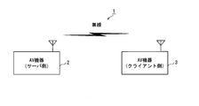
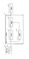
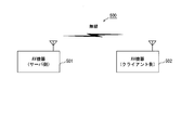
図1は本実施の形態のネットワーク構成図であり、ネットワーク1にはAV機器2,3が含まれている。
<Network configuration and operation>
FIG. 1 is a network configuration diagram according to the present embodiment. The network 1 includes AV devices 2 and 3.
本実施の形態では、AV機器2は、メディアデータを記憶保持し、メディアデータを送信するサーバ側のAV機器であり、AV機器3は、他の機器から送信されたメディアデータを受信し、受信したメディアデータを再生、表示するクライアント側のAV機器である。AV機器2は、例えば、通信機能を備えた映像コンテンツデータを記憶可能なHDD(Hard Disk Drive)レコーダ機器やBlu-ray Disk(登録商標)レコーダ機器などである。AV機器3は、通信機能を備えたテレビなどのディスプレイ装置などである。通信機能として、IEEE802.11標準規格の無線LAN(Local Area Network)などの無線通信、HD-PLC(登録商標)などの電力線通信、Ethernet(登録商標)などの通信、同軸ケーブル通信などがあり、図1では通信機能を無線通信で表している。
In the present embodiment, the AV device 2 is a server-side AV device that stores and holds media data and transmits media data. The AV device 3 receives and receives media data transmitted from other devices. It is an AV device on the client side that reproduces and displays the media data. The AV device 2 is, for example, an HDD (Hard Disk Drive) recorder device or a Blu-ray Disk (registered trademark) recorder device capable of storing video content data having a communication function. The AV device 3 is a display device such as a television having a communication function. Communication functions include wireless communication such as IEEE 802.11 standard wireless LAN (Local Area Network), power line communication such as HD-PLC (registered trademark), communication such as Ethernet (registered trademark), coaxial cable communication, etc. In FIG. 1, the communication function is represented by wireless communication.
AV機器2は例えば蓄積している映像コンテンツデータをストリーミング配信し、AV機器3はストリーミング配信されている映像コンテンツデータを受信し、受信した映像コンテンツデータを再生、表示する。これによって、視聴者はAV機器2に蓄積されている映像コンテンツデータの映像をAV機器3で視聴することができる。
For example, the AV device 2 performs streaming distribution of the stored video content data, and the AV device 3 receives the streamed video content data, and reproduces and displays the received video content data. As a result, the viewer can view the video content data stored in the AV device 2 on the AV device 3.
以下、サーバ側のAV機器2の詳細を図面を参照しつつ説明する。なお、クライアント側のAV機器3は一般的なAV機器が利用でき、詳細な説明を省略する。
Hereinafter, details of the AV device 2 on the server side will be described with reference to the drawings. The AV device 3 on the client side can use a general AV device, and detailed description thereof is omitted.
<AV機器(サーバ側)の装置構成>
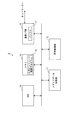
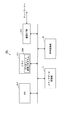
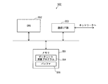
図2は図1のサーバ側のAV機器2の装置構成図であり、AV機器2は、メディアデータ記憶部11と、符号変換部12と、メモリ13と、CPU(Central Processing Unit)14と、通信インターフェース部(以下、「通信I/F部」と称する。)15とを備える。
<Device configuration of AV equipment (server side)>
2 is a device configuration diagram of the server-side AV device 2 of FIG. 1. The AV device 2 includes a media data storage unit 11, a code conversion unit 12, a memory 13, a CPU (Central Processing Unit) 14, And a communication interface unit (hereinafter referred to as “communication I / F unit”) 15.
メディアデータ記憶部11は、例えばHDDで構築され、映像データや音声データなどのメディアコンテンツを記憶保持する機能を有する。
The media data storage unit 11 is constructed of, for example, an HDD, and has a function of storing and holding media contents such as video data and audio data.
符号変換部12は、映像データや音声データなどのメディアデータのビットレート(データレート)を変換する機能を有する。メディアデータのビットレートを変換する方法として、圧縮、符号化されたメディアデータを一旦デコードし、異なるビットレートに再エンコードする方法や、メディアデータをデコードせずに、異なるビットレートに再エンコードするトランスコーディングと呼ばれる方法などがあるが、入力されたメディアデータを異なるビットレートのメディアデータに変換して出力できれば、いかなる変換方法や符号化方法で実装されていてもよい。なお、符号変換部12に入力される例えば映像データ及び音声データは、必ずしも圧縮、符号化されている必要はない。例えば、圧縮、符号化されていない映像データ及び音声データを入力して、圧縮、符号化処理を行って圧縮、符号化された映像データ及び音声データを出力してもよい。
The code conversion unit 12 has a function of converting a bit rate (data rate) of media data such as video data and audio data. The media data bit rate can be converted by once decoding the compressed and encoded media data and re-encoding it to a different bit rate, or by trans-encoding the media data to a different bit rate without decoding it. Although there is a method called coding, etc., any conversion method or encoding method may be used as long as input media data can be converted into media data of different bit rates and output. Note that, for example, video data and audio data input to the code conversion unit 12 do not necessarily have to be compressed and encoded. For example, uncompressed and encoded video data and audio data may be input, compression and encoding processing may be performed, and compressed and encoded video data and audio data may be output.
メモリ13は、例えば、ROM(Read Only Memory)やRAM(Random Access Memory)などの半導体メモリで構築される。メモリ13は、各種制御プログラムや各種アプリケーションプログラムなどのプログラムを記憶保持しており、例えば、通信I/F部15内の後述するバッファ17へ入力される所定時間当たりのメディアデータのデータ量を制御するためのプログラム(以下、「入力ビットレート制御プログラム」と言う。)16を記憶保持している。また、メモリ13は、CPU14が動作する際に使用する領域を有する。
The memory 13 is constructed by a semiconductor memory such as ROM (Read Only Memory) or RAM (Random Access Memory). The memory 13 stores programs such as various control programs and various application programs. For example, the memory 13 controls the data amount of media data per predetermined time input to a buffer 17 described later in the communication I / F unit 15. A program (hereinafter referred to as “input bit rate control program”) 16 is stored and held. Further, the memory 13 has an area used when the CPU 14 operates.
CPU14は、メモリ13に記憶保持されているプログラムを読み出し、読み出したプログラムを実行することによって、AV機器2全体の各種制御や各種演算を行う機能を有する。例えば、CPU14は、メモリ13から入力ビットレート制御プログラム16を読み出して、読み出した入力ビットレート制御プログラム16を実行する。なお、この処理については、図4から図7を参照して後述する。
The CPU 14 has a function of performing various controls and various calculations of the entire AV device 2 by reading the program stored in the memory 13 and executing the read program. For example, the CPU 14 reads the input bit rate control program 16 from the memory 13 and executes the read input bit rate control program 16. This process will be described later with reference to FIGS.
通信I/F部15は、ネットワークを介してデータを送受信する機能、例えば、データ信号の変復調やメディアアクセス制御を行う機能を有し、ここでは、無線通信の通信I/F部とする。通信I/F部15は内部にバッファ17を有し、バッファ17は送信バッファである。なお、バッファ17については図3を参照して後述する。
The communication I / F unit 15 has a function of transmitting and receiving data via a network, for example, a function of performing modulation / demodulation of a data signal and media access control, and is a communication I / F unit for wireless communication here. The communication I / F unit 15 has a buffer 17 therein, and the buffer 17 is a transmission buffer. The buffer 17 will be described later with reference to FIG.
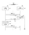
例えば、メディアデータをクライアント側のAV機器3へ送信する場合、CPU14は入力ビットレート制御プログラム16を実行して後述する入力ビットレート更新値を算出し、符号変換部12は算出された入力ビットレート更新値に従ってメディアデータ記憶部11に記憶保持されているメディアデータに対してビットレート(データレート)の変換を施す。そして、通信I/F部15は変換されて得られたメディアデータをバッファ17に一時的に蓄積しながらネットワークを介してクライアント側のAV機器3へ送出する。
For example, when transmitting media data to the AV device 3 on the client side, the CPU 14 executes an input bit rate control program 16 to calculate an input bit rate update value, which will be described later, and the code conversion unit 12 calculates the calculated input bit rate. Bit rate (data rate) conversion is performed on the media data stored and held in the media data storage unit 11 in accordance with the updated value. The communication I / F unit 15 then sends the media data obtained by the conversion to the AV device 3 on the client side via the network while temporarily storing it in the buffer 17.
このように、AV機器2内にバッファ17に入力されるデータのビットレート(データレート)を変更する符号変換部12を備えることで、入力ビットレートの変更を即座に行うことが可能になる。
Thus, by providing the code conversion unit 12 that changes the bit rate (data rate) of the data input to the buffer 17 in the AV device 2, the input bit rate can be changed immediately.
<バッファの構成>
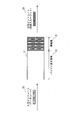
図3は図2のバッファ17の一構成例を説明するための図である。
<Buffer configuration>
FIG. 3 is a diagram for explaining a configuration example of the buffer 17 of FIG.
蓄積量21はバッファ17に蓄積されているデータのデータ量を表し、バッファ空き容量22はバッファ17に蓄積可能な残りのデータのデータ量を表す。データ量の単位は蓄積量21及びバッファ空き容量22ともビット或いはバイト等で表すことができ、本実施の形態ではビットを用いて説明する。
The storage amount 21 represents the data amount of data stored in the buffer 17, and the buffer free space 22 represents the data amount of remaining data that can be stored in the buffer 17. The unit of the data amount can be expressed by bits or bytes for both the storage amount 21 and the buffer free capacity 22, and will be described using bits in this embodiment.
入力ビットレート23は、バッファ17に入力されるメディアデータの単位時間当たりのデータ量を表し、出力ビットレート24はバッファ17から出力されるメディアデータの単位時間当たりのデータ量を表す。本実施の形態では、入力ビットレート23及び出力ビットレート24の単位としてbps(bit per second)を用いて説明する。ここでは、入力ビットレート23は符号変換部12から出力されるメディアデータのビットレート(データレート)と等しく、出力ビットレート24は通信I/F部15がメディアデータを送信する際の伝送スループットと等しいとする。
The input bit rate 23 represents the data amount per unit time of the media data input to the buffer 17, and the output bit rate 24 represents the data amount per unit time of the media data output from the buffer 17. In the present embodiment, a description will be given using bps (bit per second) as a unit of the input bit rate 23 and the output bit rate 24. Here, the input bit rate 23 is equal to the bit rate (data rate) of the media data output from the code conversion unit 12, and the output bit rate 24 is the transmission throughput when the communication I / F unit 15 transmits the media data. Suppose they are equal.
バッファ17は、FIFO(First In First Out)の動作原理に従い、入力されたメディアデータを入力された順に出力する。このとき、入力ビットレート23と出力ビットレート24とが等しい場合、バッファ17の蓄積量21は変化しない。入力ビットレート23と出力ビットレート24とが等しくない場合、入力ビットレート23と出力ビットレート24との差分に応じて、バッファ17の蓄積量21は増減する。つまり、入力ビットレート23が出力ビットレート24より大きい場合にはバッファ17の蓄積量21は増加し、入力ビットレート23が出力ビットレート24より小さい場合にはバッファ17の蓄積量21は減少する。
The buffer 17 outputs the input media data in the input order in accordance with the operation principle of FIFO (First In First Out). At this time, when the input bit rate 23 and the output bit rate 24 are equal, the accumulation amount 21 of the buffer 17 does not change. When the input bit rate 23 and the output bit rate 24 are not equal, the accumulation amount 21 of the buffer 17 increases or decreases according to the difference between the input bit rate 23 and the output bit rate 24. That is, when the input bit rate 23 is greater than the output bit rate 24, the accumulation amount 21 of the buffer 17 increases, and when the input bit rate 23 is less than the output bit rate 24, the accumulation amount 21 of the buffer 17 decreases.
例えば、入力ビットレート23が12Mbpsで出力ビットレート24が8Mbpsの場合、4Mbpsの速度でバッファ17の蓄積量21は増加し、言い換えると、4Mbpsの速度でバッファ17のバッファ空き容量22は減少する。一方、入力ビットレート23が6Mbpsで出力ビットレート24が9Mbpsの場合、3Mbpsの速度でバッファ17の蓄積量21は減少し、言い換えると、3Mbpsの速度でバッファ17のバッファ空き容量22は増加する。
For example, when the input bit rate 23 is 12 Mbps and the output bit rate 24 is 8 Mbps, the accumulated amount 21 of the buffer 17 increases at a speed of 4 Mbps, in other words, the buffer free capacity 22 of the buffer 17 decreases at a speed of 4 Mbps. On the other hand, when the input bit rate 23 is 6 Mbps and the output bit rate 24 is 9 Mbps, the accumulated amount 21 of the buffer 17 decreases at a speed of 3 Mbps, in other words, the buffer free capacity 22 of the buffer 17 increases at a speed of 3 Mbps.
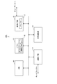
<CPUの機能構成>
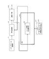
図4は図2のCPU14の機能構成図である。但し、図4には、CPU14の機能構成の理解を容易にするため、AV機器2の他の構成要素も図示している。
<Functional configuration of CPU>
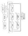
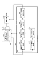
FIG. 4 is a functional configuration diagram of the CPU 14 of FIG. However, FIG. 4 also illustrates other components of the AV device 2 in order to facilitate understanding of the functional configuration of the CPU 14.
CPU14は、メモリ13からそれに記憶保持されている入力ビットレート制御プログラム16を読み出し、読み出した入力ビットレート制御プログラム16を実行する。これによって、CPU14は、出力ビットレート検出部31、バッファ空き容量検出部32、減少率/増加率演算部33、入力ビットレート演算部34、及び入力ビットレート決定部35として機能する。
The CPU 14 reads the input bit rate control program 16 stored and held in the memory 13 and executes the read input bit rate control program 16. Thus, the CPU 14 functions as an output bit rate detection unit 31, a buffer free space detection unit 32, a decrease rate / increase rate calculation unit 33, an input bit rate calculation unit 34, and an input bit rate determination unit 35.
出力ビットレート検出部31は、バッファ17から出力されるメディアデータの出力ビットレート24の値即ち伝送スループットの値を検出し、検出した出力ビットレート24の値を入力ビットレート演算部34へ出力する。
The output bit rate detection unit 31 detects the value of the output bit rate 24 of the media data output from the buffer 17, that is, the value of the transmission throughput, and outputs the detected value of the output bit rate 24 to the input bit rate calculation unit 34. .
ここで、出力ビットレート検出部31の機能構成について図5を参照しつつ説明する。図5は図4の出力ビットレート検出部31の機能構成図である。なお、図5では、出力ビットレート検出部31の内部要素と通信I/F部15及び入力ビットレート演算部34の接続関係を明確にするために、通信I/F部15及び入力ビットレート演算部34も図示している。
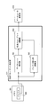
Here, the functional configuration of the output bit rate detection unit 31 will be described with reference to FIG. FIG. 5 is a functional configuration diagram of the output bit rate detection unit 31 of FIG. In FIG. 5, in order to clarify the connection relationship between the internal elements of the output bit rate detection unit 31 and the communication I / F unit 15 and the input bit rate calculation unit 34, the communication I / F unit 15 and the input bit rate calculation are performed. Part 34 is also illustrated.
出力ビットレート検出部31は、入力ビットレート検出部41、バッファ変化率演算部42、及び出力ビットレート演算部43として機能する。
The output bit rate detection unit 31 functions as an input bit rate detection unit 41, a buffer change rate calculation unit 42, and an output bit rate calculation unit 43.
入力ビットレート検出部41は、バッファ17に入力されるメディアデータの単位時間当たりのデータ量を検出し、検出結果を入力ビットレート23の値として出力ビットレート演算部43へ出力する。なお、入力ビット検出部41は、入力ビットレート決定部35が符号変換部12に対して出力する後述の入力ビットレート更新値を入力ビットレート23の値として検出するようにしてもよい。
The input bit rate detection unit 41 detects the data amount per unit time of the media data input to the buffer 17 and outputs the detection result to the output bit rate calculation unit 43 as the value of the input bit rate 23. Note that the input bit detection unit 41 may detect an input bit rate update value (described later) output from the input bit rate determination unit 35 to the code conversion unit 12 as the value of the input bit rate 23.
バッファ変化率演算部42は、バッファ17の蓄積量21の単位時間当たりの増加や減少を変化率として算出し、算出した変化率の値を出力ビットレート演算部43へ出力する。但し、蓄積量21が増加した場合の変化率を正の値で表し、蓄積量21が減少した場合の変化率を負の値で表すことにする。
The buffer change rate calculation unit 42 calculates an increase or decrease in the accumulated amount 21 of the buffer 17 per unit time as the change rate, and outputs the calculated change rate value to the output bit rate calculation unit 43. However, the rate of change when the accumulated amount 21 increases is represented by a positive value, and the rate of change when the accumulated amount 21 decreases is represented by a negative value.
出力ビットレート演算部43は、入力ビットレート検出部41から入力された入力ビットレート23の値からバッファ変化率演算部42から入力された変化率の値を減算することによって出力ビットレート24の値を算出し(出力ビットレート=入力ビットレート-変化率)、算出した出力ビットレート24の値を入力ビットレート演算部34へ出力する。
The output bit rate calculation unit 43 subtracts the value of the change rate input from the buffer change rate calculation unit 42 from the value of the input bit rate 23 input from the input bit rate detection unit 41, thereby obtaining the value of the output bit rate 24. Is calculated (output bit rate = input bit rate−change rate), and the value of the calculated output bit rate 24 is output to the input bit rate calculation unit 34.
バッファ空き容量検出部32は、バッファ17のバッファ空き容量22の値を検出し、検出したバッファ空き容量22の値を減少率/増加率演算部33へ出力する。
The buffer free capacity detection unit 32 detects the value of the buffer free capacity 22 of the buffer 17 and outputs the detected value of the buffer free capacity 22 to the decrease rate / increase rate calculation unit 33.
減少率/増加率演算部33は、バッファ空き容量検出部32から入力されたバッファ17のバッファ空き容量22の値を利用して、バッファ17のバッファ空き容量22の許容される減少率の値及び増加率の値を算出し、算出した減少率の値及び増加率の値を入力ビットレート演算部34へ出力する。
The decrease rate / increase rate calculation unit 33 uses the value of the buffer free space 22 of the buffer 17 input from the buffer free space detection unit 32 and the value of the allowable decrease rate of the buffer free space 22 of the buffer 17 and The increase rate value is calculated, and the calculated decrease rate value and increase rate value are output to the input bit rate calculation unit 34.
減少率/増加率演算部33は増加率の算出を次のようにして行う。減少率/増加率演算部33は、予め設定された増加率設定値からバッファ17のバッファ空き容量22の値を減算し、減算値を予め定められた一定時間(以下、「確保時間」と言う。)で除算することによって、増加率の値を算出する(増加率=(増加率設定値-バッファ空き容量)/確保時間)。但し、増加率設定値とは、入力ビットレート23を制御してバッファ空き容量22の増減を調整し、確保時間後の目標とするバッファ空き容量22の最大値であり、増加率設定値は主として入力ビットレートを増大させる制御を行う際に利用される。算出される増加率の値は、確保時間後に増加率設定値までバッファ空き容量22の値を増加させようとした場合に必要な単位時間当たりのバッファ空き容量22の増加率の値ということになる。
The decrease rate / increase rate calculation unit 33 calculates the increase rate as follows. The decrease rate / increase rate calculation unit 33 subtracts the value of the buffer free space 22 of the buffer 17 from a preset increase rate set value, and the subtracted value is referred to as a predetermined time (hereinafter referred to as “reserved time”). )) To calculate an increase rate value (increase rate = (increase rate set value−buffer free capacity) / reserved time). However, the increase rate set value is the maximum value of the target buffer free space 22 after the secured time by adjusting the increase / decrease of the buffer free space 22 by controlling the input bit rate 23, and the increase rate set value is mainly This is used when performing control to increase the input bit rate. The calculated increase rate value is a value of the increase rate of the buffer free space 22 per unit time required when the value of the buffer free space 22 is increased to the increase rate set value after the secured time. .
また、減少率/増加率演算部33は減少率の算出を次のようにして行う。減少率/増加率演算部33は、バッファ17のバッファ空き容量22の値から予め設定された減少率設定値を減算し、減算値を確保時間で除算することによって、減少率の値を算出する(減少率=(バッファ空き容量-減少率設定値)/確保時間)。但し、減少率設定値とは、入力ビットレート23を制御してバッファ空き容量22の増減を調整し、確保時間後の目標とするバッファ空き容量22の最小値であり、減少率設定値は主として入力ビットレートを低下させる制御を行う際に利用される。算出される減少率の値は、確保時間後に減少率設定値までバッファ空き容量22の値を減少させようとした場合に必要な単位時間当たりのバッファ空き容量22の減少率の値ということになる。
Further, the decrease rate / increase rate calculation unit 33 calculates the decrease rate as follows. The decrease rate / increase rate calculation unit 33 calculates a decrease rate value by subtracting a preset decrease rate set value from the value of the buffer free capacity 22 of the buffer 17 and dividing the subtracted value by the reserved time. (Decrease rate = (buffer free capacity−decrease rate setting value) / reserved time). However, the decrease rate setting value is the minimum value of the target buffer free space 22 after adjusting the increase / decrease of the buffer free space 22 by controlling the input bit rate 23, and the decrease rate set value is mainly This is used when performing control to lower the input bit rate. The calculated decrease rate value is a decrease rate value of the buffer free space 22 per unit time required when the value of the buffer free space 22 is to be decreased to the decrease rate set value after the secured time. .
但し、増加率設定値は減少率設定値より大きい。増加率設定値は設計時に任意の値にすることができるが、例えば増加率設定値をバッファ17の最大蓄積量としてもよい。減少率設定値は設計時に任意の値にすることができるが、例えば減少率設定値をゼロに設定してもよい。増加率及び減少率の算出に用いる確保時間は設計時に任意の値に設定することができるが、例えば連続的に発生する伝送路誤りの継続時間とすることができる。なお、増加率の算出に用いる確保時間と減少率の算出に用いる確保時間とを同じ値にしてもよいし、異なる値にしてもよい。
However, the increase rate set value is larger than the decrease rate set value. The increase rate set value can be set to an arbitrary value at the time of design. For example, the increase rate set value may be set as the maximum accumulation amount of the buffer 17. Although the reduction rate setting value can be set to an arbitrary value at the time of design, for example, the reduction rate setting value may be set to zero. The securing time used for calculating the increase rate and the decrease rate can be set to an arbitrary value at the time of design, but can be set as, for example, the duration of a transmission path error that occurs continuously. The securing time used for calculating the increase rate and the securing time used for calculating the decrease rate may be the same value or different values.
入力ビットレート演算部34は、出力ビットレート検出部31から入力された出力ビットレートの値に減少率/増加率演算部33から入力された減少率の値を加算し、加算値を入力ビットレート上限値として入力ビットレート決定部35へ出力する(入力ビットレート上限値=出力ビットレート+減少率)。但し、入力ビットレート上限値は、入力ビットレートを更新する際に許容される入力ビットレートの上限値である。
The input bit rate calculation unit 34 adds the decrease rate value input from the decrease rate / increase rate calculation unit 33 to the output bit rate value input from the output bit rate detection unit 31, and uses the added value as the input bit rate. The upper limit value is output to the input bit rate determining unit 35 (input bit rate upper limit value = output bit rate + decrease rate). However, the input bit rate upper limit value is an upper limit value of the input bit rate allowed when the input bit rate is updated.
また、入力ビットレート演算部34は、出力ビットレート検出部31から入力された出力ビットレートの値から減少率/増加率演算部33から入力された増加率の値を減算し、減算値を入力ビットレート下限値として入力ビットレート決定部35へ出力する(入力ビットレート下限値=出力ビットレート-増加率)。但し、入力ビットレート下限値は、入力ビットレートを更新する際に許容される入力ビットレートの下限値である。
The input bit rate calculation unit 34 subtracts the increase rate value input from the decrease rate / increase rate calculation unit 33 from the output bit rate value input from the output bit rate detection unit 31 and inputs the subtraction value. The bit rate lower limit value is output to the input bit rate determination unit 35 (input bit rate lower limit value = output bit rate−increase rate). However, the input bit rate lower limit value is a lower limit value of the input bit rate that is allowed when the input bit rate is updated.
入力ビットレート決定部35は、図5の入力ビットレート検出部41で検出される現在の入力ビットレートの値と、入力ビットレート演算部34から入力される入力ビットレート上限値及び入力ビットレート下限値と、送信するメディアデータに設定可能な最大データレートの値とに基づいて、入力ビットレート更新値を決定し、決定した入力ビットレート更新値を符号変換部12に対して通知する。但し、現在の入力ビットレートの値として符号変換部12に対して出力する入力ビットレート更新値を用いるようにしてもよい。なお、符号変換部12は、メディアデータ記憶部11に記憶されているメディアデータのビットレート(データレート)をCPU14の入力ビットレート決定部35から通知された入力ビットレート更新値に従って変換し、変換により得られたメディアデータを通信I/F部15内のバッファ17へ出力する。
The input bit rate determination unit 35 includes the current input bit rate value detected by the input bit rate detection unit 41 in FIG. 5, the input bit rate upper limit value and the input bit rate lower limit value input from the input bit rate calculation unit 34. The input bit rate update value is determined based on the value and the value of the maximum data rate that can be set for the media data to be transmitted, and the determined input bit rate update value is notified to the code conversion unit 12. However, the input bit rate update value output to the code conversion unit 12 may be used as the current input bit rate value. The code conversion unit 12 converts the bit rate (data rate) of the media data stored in the media data storage unit 11 according to the input bit rate update value notified from the input bit rate determination unit 35 of the CPU 14 and converts the bit rate. The media data obtained by the above is output to the buffer 17 in the communication I / F unit 15.
詳述すれば、入力ビットレート決定部35は、現在の入力ビットレートの値が入力ビットレート下限値以上入力ビットレート上限値以下であれば、入力ビットレート更新値を現在の入力ビットレートの値に設定する。入力ビットレート決定部35は、現在の入力ビットレートの値が入力ビットレート下限値より小さければ、入力ビットレート更新値を入力ビットレート下限値に設定し、現在の入力ビットレートの値が入力ビットレート上限値より大きければ、入力ビットレート更新値を入力ビットレート上限値に設定する。
Specifically, if the current input bit rate value is not less than the input bit rate lower limit value and not more than the input bit rate upper limit value, the input bit rate determination unit 35 sets the input bit rate update value to the current input bit rate value. Set to. If the current input bit rate value is smaller than the input bit rate lower limit value, the input bit rate determining unit 35 sets the input bit rate update value to the input bit rate lower limit value, and the current input bit rate value is set to the input bit rate. If it is larger than the rate upper limit value, the input bit rate update value is set to the input bit rate upper limit value.
さらに、入力ビットレート決定部35は、上述したように設定した入力ビットレート更新値が送信するメディアデータに設定可能な最大データレートの値より大きければ、入力ビットレート更新値を最大データレートの値に再設定する。
Further, if the input bit rate update value set as described above is larger than the maximum data rate value that can be set for the media data to be transmitted, the input bit rate determination unit 35 sets the input bit rate update value to the maximum data rate value. Reset to.
図4及び図5を用いて説明したCPU14の構成によれば、バッファ17のバッファ空き容量22、入力ビットレート23、及びバッファ17のバッファ空き容量22の変化率というバッファの状態を検出するだけで、入力ビットレートの制御を行うことができる。このため、入力ビットレートの制御が容易になり、AV機器2の構成を簡略化することができる。
According to the configuration of the CPU 14 described with reference to FIGS. 4 and 5, it is only necessary to detect the buffer state such as the buffer free capacity 22 of the buffer 17, the input bit rate 23, and the rate of change of the buffer free capacity 22 of the buffer 17. The input bit rate can be controlled. For this reason, control of the input bit rate is facilitated, and the configuration of the AV device 2 can be simplified.
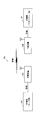
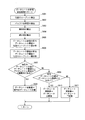
<CPUの動作>
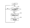
図6は図2のCPU14が行う入力ビットレート制御処理の流れを示すフローチャートである。但し、CPU14はメモリ13からそれに記憶されている入力ビットレート制御プログラム16を読み出し、読み出した入力ビットレート制御プログラム16を実行することによって、図6及び後述する図7のフローチャートの処理を実行する。
<CPU operation>
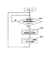
FIG. 6 is a flowchart showing the flow of input bit rate control processing performed by the CPU 14 of FIG. However, the CPU 14 reads the input bit rate control program 16 stored in the memory 13 and executes the read input bit rate control program 16, thereby executing the processing of the flowchart of FIG. 6 and FIG.
CPU14は、バッファ17のバッファ空き容量22の値が予め設定された制御開始閾値より小さいかを判定する(ステップS101)。
The CPU 14 determines whether or not the value of the buffer free space 22 of the buffer 17 is smaller than a preset control start threshold (step S101).
バッファ空き容量22の値が制御開始閾値以上である間(S101:NO)、ステップS101の処理が繰り返し行われ、入力ビットレート23の更新は行われない。例えば、バッファ空き容量22の値が制御開始閾値より小さくなるまで、伝送スループットが安定していると判断し、入力ビットレート23の更新が行われない。また、伝送路の状態が回復してバッファ空き容量22の値が制御開始閾値以上になってから再度バッファ空き容量22の値が制御開始閾値よりも小さくなるまで、伝送スループットが安定していると判断し、入力ビットレート23の値はバッファ空き容量22の値が制御開始閾値以上になった時点の入力ビットレート23の値で固定される。このように、バッファ17のバッファ空き容量22の値が制御開始閾値以上にある場合は伝送スループットが安定していると判断し、伝送スループットが安定している場合におけるバッファ17のバッファ空き容量22の瞬時的な変動に対して入力ビットレート23の更新は行われない。このため、伝送スループットが安定した状態では入力ビットレート23が一定値に保たれる。これにより、例えば映像データの送信時に、伝送スループットが安定した状態ではクライアント側のAV機器3で再生される映像の解像度が下がったりフレームレートが低くなったりする変化が発生せず、視聴者は違和感なく映像を視聴することができる。
While the value of the buffer free space 22 is equal to or greater than the control start threshold (S101: NO), the process of step S101 is repeated and the input bit rate 23 is not updated. For example, it is determined that the transmission throughput is stable until the value of the buffer free capacity 22 becomes smaller than the control start threshold, and the input bit rate 23 is not updated. Further, when the transmission path state is recovered and the value of the buffer free capacity 22 becomes equal to or greater than the control start threshold, the transmission throughput is stable until the value of the buffer free capacity 22 becomes smaller than the control start threshold again. Thus, the value of the input bit rate 23 is fixed at the value of the input bit rate 23 at the time when the value of the buffer free space 22 becomes equal to or greater than the control start threshold value. Thus, when the value of the buffer free capacity 22 of the buffer 17 is equal to or greater than the control start threshold, it is determined that the transmission throughput is stable, and the buffer free capacity 22 of the buffer 17 when the transmission throughput is stable is determined. The input bit rate 23 is not updated for instantaneous fluctuations. For this reason, the input bit rate 23 is kept constant when the transmission throughput is stable. As a result, for example, when transmitting video data, when the transmission throughput is stable, there is no change in the resolution of the video reproduced by the AV device 3 on the client side or the frame rate is lowered, and the viewer feels uncomfortable. You can watch the video without
一方、バッファ空き容量22の値が制御開始閾値より小さいと判定された場合(S101:YES)、CPU14は、図7に処理の流れを示す入力ビットレート更新値決定処理を実行することによって入力ビットレート更新値を決定する(ステップS102)。そして、CPU14の入力ビットレート決定部35は、ステップS102で決定された入力ビットレート更新値を符号変換部12に対して通知し(ステップS103)、ステップS101の処理が行われる。符号変換部12は、メディアデータ記憶部11に記憶されているメディアデータのビットレート(データレート)を通知された入力ビットレート更新値に従って変換し、変換により得られたメディアデータを通信I/F部15内のバッファ17へ出力する。通信I/F部15はバッファ17に蓄積されているメディアデータをネットワークを介して例えばクライアント側のAV機器3へ送信する。
On the other hand, when it is determined that the value of the buffer free space 22 is smaller than the control start threshold (S101: YES), the CPU 14 executes the input bit rate update value determination process whose process flow is shown in FIG. A rate update value is determined (step S102). Then, the input bit rate determination unit 35 of the CPU 14 notifies the code conversion unit 12 of the input bit rate update value determined in step S102 (step S103), and the process of step S101 is performed. The code conversion unit 12 converts the bit rate (data rate) of the media data stored in the media data storage unit 11 according to the notified input bit rate update value, and converts the media data obtained by the conversion to the communication I / F. The data is output to the buffer 17 in the unit 15. The communication I / F unit 15 transmits the media data stored in the buffer 17 to, for example, the AV device 3 on the client side via the network.
[入力ビットレート更新値決定処理]
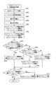
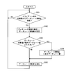
図7は図6の入力ビットレート更新値決定処理(ステップS102)の流れを示すフローチャートである。
[Input bit rate update value decision processing]
FIG. 7 is a flowchart showing the flow of the input bit rate update value determination process (step S102) of FIG.
出力ビットレート検出部31において、入力ビットレート検出部41はバッファ17に入力されているメディアデータの入力ビットレート23の値を検出し、バッファ変化率演算部42はバッファ17の蓄積量21の変化率の値を算出する。そして、出力ビットレート演算部43は検出された入力ビットレート23の値から算出された変化率の値を減算することによって、出力ビットレート24の値を算出する(ステップS201)。
In the output bit rate detector 31, the input bit rate detector 41 detects the value of the input bit rate 23 of the media data input to the buffer 17, and the buffer change rate calculator 42 changes the accumulated amount 21 of the buffer 17. Calculate the rate value. Then, the output bit rate calculation unit 43 calculates the value of the output bit rate 24 by subtracting the calculated change rate value from the detected value of the input bit rate 23 (step S201).
バッファ空き容量検出部32はバッファ17のバッファ空き容量22の値を検出する(ステップS202)。減少率/増加率演算部33は、増加率設定値からステップS202で検出されたバッファ空き容量22の値を減算し、減算値を確保時間で除算することによって、増加率の値を算出する(ステップS203)。また、減少率/増加率演算部33は、ステップS202で検出されたバッファ空き容量22の値から減少率設定値を減算し、減算値を確保時間で除算することによって、減少率の値を算出する(ステップS204)。
The buffer free capacity detection unit 32 detects the value of the buffer free capacity 22 of the buffer 17 (step S202). The decrease rate / increase rate calculation unit 33 calculates the value of the increase rate by subtracting the value of the buffer free space 22 detected in step S202 from the increase rate set value and dividing the subtracted value by the reserved time ( Step S203). Further, the decrease rate / increase rate calculation unit 33 subtracts the decrease rate set value from the value of the buffer free space 22 detected in step S202, and calculates the decrease rate value by dividing the subtracted value by the reserved time. (Step S204).
入力ビットレート演算部34は、ステップS201で検出された出力ビットレートの値にステップS204で算出された減少率の値を加算し、加算値を入力ビットレート上限値とする(ステップS205)。また、入力ビットレート演算部34は、ステップS201で検出された出力ビットレートの値からステップS203で算出された増加率の値を減算し、減算値を入力ビットレート下限値とする(ステップS206)。
The input bit rate calculation unit 34 adds the value of the decrease rate calculated in step S204 to the value of the output bit rate detected in step S201, and sets the added value as the input bit rate upper limit value (step S205). Further, the input bit rate calculation unit 34 subtracts the value of the increase rate calculated in step S203 from the value of the output bit rate detected in step S201, and sets the subtraction value as the input bit rate lower limit value (step S206). .
入力ビットレート決定部35は、現在の入力ビットレートの値がステップS206で得られた入力ビットレート下限値以上ステップS205で得られた入力ビットレート上限値以下の範囲内であるかを判定する(ステップS207)。
The input bit rate determination unit 35 determines whether or not the current input bit rate value is within a range not less than the input bit rate lower limit value obtained in step S206 and not more than the input bit rate upper limit value obtained in step S205 ( Step S207).
現在の入力ビットレートの値がその範囲内であれば(S207:YES)、入力ビットレート決定部35は、入力ビットレート更新値を現在の入力ビットレートの値に設定し(ステップS208)、ステップS212の処理へ移行する。このようにすることにより、伝送スループットが回復した状態から再度低下した場合や伝送スループットが低下した状態から回復した場合に、現在の入力ビットレートの値が入力ビットレート下限値以上入力ビットレート上限値以下の範囲内であれば入力ビットレートの更新が行われない。このため、現在の入力ビットレートの値が上記の範囲内であれば伝送スループットが変動しても入力ビットレートは変動することなく安定する。これにより、例えばクライアント側のAV機器3で再生される映像の解像度やフレームレートが急激に上がったり下がったりするような状況を回避でき、視聴者は安定した品質の映像を視聴することができる。
If the current input bit rate value is within the range (S207: YES), the input bit rate determination unit 35 sets the input bit rate update value to the current input bit rate value (step S208). The process proceeds to S212. In this way, when the transmission throughput drops again from the recovered state or when recovering from the reduced transmission throughput, the current input bit rate value is greater than or equal to the input bit rate lower limit value. If it is within the following range, the input bit rate is not updated. For this reason, if the current input bit rate value is within the above range, the input bit rate is stable without fluctuation even if the transmission throughput varies. As a result, for example, it is possible to avoid a situation in which the resolution and frame rate of the video reproduced by the AV device 3 on the client side suddenly increase or decrease, and the viewer can view the video with stable quality.
一方、現在の入力ビットレートの値がその範囲内になければ(S207:NO)、入力ビットレート決定部35は、現在の入力ビットレートの値が入力ビットレート上限値より大きいかを判定する(ステップS209)。
On the other hand, if the current input bit rate value is not within the range (S207: NO), the input bit rate determination unit 35 determines whether or not the current input bit rate value is greater than the input bit rate upper limit value ( Step S209).
現在の入力ビットレートの値が入力ビットレート上限値より大きければ(S209:YES)、出力ビットレートの低下かバッファ17のバッファ空き容量22の低下により入力ビットレート上限値が現在の入力ビットレートの値より低下した状況であることから、入力ビットレート決定部35は、入力ビットレートを下げるべく、入力ビットレート更新値を入力ビットレート上限値に設定し(ステップS210)、ステップS212の処理へ移行する。
If the current input bit rate value is larger than the input bit rate upper limit value (S209: YES), the input bit rate upper limit value is equal to the current input bit rate due to a decrease in the output bit rate or a decrease in the buffer free capacity 22 of the buffer 17. Because the situation is lower than the value, the input bit rate determination unit 35 sets the input bit rate update value to the input bit rate upper limit value to lower the input bit rate (step S210), and proceeds to the process of step S212. To do.
一方、現在の入力ビットレートの値が入力ビットレート上限値より大きくなければ、つまり、現在の入力ビットレートの値が入力ビットレート下限値より小さければ(S209:NO)、出力ビットレートの増大かバッファ17のバッファ空き容量22の増加により入力ビットレート下限値が現在の入力ビットレートの値より増大した状況であることから、入力ビットレート決定部35は、入力ビットレートを上げるべく、入力ビットレート更新値を入力ビットレート下限値に設定し(ステップS211)、ステップS212の処理へ移行する。
On the other hand, if the current input bit rate value is not larger than the input bit rate upper limit value, that is, if the current input bit rate value is smaller than the input bit rate lower limit value (S209: NO), is the output bit rate increased? Since the input bit rate lower limit value has increased from the current input bit rate value due to the increase in the buffer free space 22 of the buffer 17, the input bit rate determination unit 35 is configured to increase the input bit rate. The update value is set to the input bit rate lower limit value (step S211), and the process proceeds to step S212.
入力ビットレート決定部35は、ステップS208、ステップS210又はステップS211で設定された入力ビットレート更新値が、送信するメディアデータに設定可能な最大データレートの値より大きいかを判定する(ステップS212)。設定された入力ビットレート更新値が最大データレートの値より大きければ(S212:YES)、入力ビットレート決定部35は、入力ビットレート更新値を最大データレートの値に再設定し(ステップS213)、図6のステップS103が行われる。このようにすることにより、符号変換部12に通知される入力ビットレート更新値が最大データレートの値を超えることがなくなるため、符号変換部12が最大データレートの値を超える入力ビットレート更新値に従ってメディアデータのビットレート(データレート)を変換することがなく、メディアデータの変換時のエラー発生を回避することができる。一方、設定された入力ビットレート更新値が最大データレートの値以下であれば(S212:NO)、入力ビットレート更新値を再設定することなく、図6のステップS103が行われる。
The input bit rate determination unit 35 determines whether the input bit rate update value set in step S208, step S210, or step S211 is greater than the maximum data rate that can be set for the media data to be transmitted (step S212). . If the set input bit rate update value is larger than the maximum data rate value (S212: YES), the input bit rate determination unit 35 resets the input bit rate update value to the maximum data rate value (step S213). Step S103 of FIG. 6 is performed. By doing in this way, since the input bit rate update value notified to the code conversion unit 12 does not exceed the maximum data rate value, the input bit rate update value at which the code conversion unit 12 exceeds the maximum data rate value. Accordingly, the bit rate (data rate) of the media data is not converted, and an error can be avoided when converting the media data. On the other hand, if the set input bit rate update value is less than or equal to the maximum data rate value (S212: NO), step S103 in FIG. 6 is performed without resetting the input bit rate update value.
<入力ビットレートの制御例>
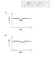
入力ビットレートの制御の一例として、伝送スループットが低下し、一定時間後に伝送スループットが回復する状況におけるバッファ17へ入力されるメディアデータの入力ビットレート即ちメディアデータのデータレートの制御について図8及び図9を参照しつつ説明する。
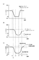
<Control example of input bit rate>
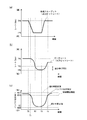
As an example of the control of the input bit rate, the control of the input bit rate of the media data input to the buffer 17, that is, the data rate of the media data in a situation where the transmission throughput decreases and the transmission throughput recovers after a certain period of time is shown in FIGS. This will be described with reference to FIG.
図8(a)及び図9(a)は、伝送スループット即ちバッファ17から出力されるメディアデータの出力ビットレート24の時間的変動を示す図であり、縦軸はレート(bps)を、横軸は時間を表す。図8(a)及び図9(a)では、時間T0で伝送路の状態の悪化が発生して伝送スループットが急激に下がり始め、一定時間後の時間T3で伝送路の状態が回復して伝送スループットが急激に上がり始めている様子が示されている。
8 (a) and 9 (a) are diagrams showing the transmission throughput, that is, the temporal variation of the output bit rate 24 of the media data output from the buffer 17, and the vertical axis indicates the rate (bps) and the horizontal axis. Represents time. In FIGS. 8A and 9A, the transmission path state deteriorates at time T0 and the transmission throughput starts to drop sharply, and the transmission path state recovers at time T3 after a certain period of time for transmission. It shows how the throughput is starting to rise sharply.
図8(b)及び図9(b)は、送信されるメディアデータのデータレート即ちバッファ17に入力されるメディアデータの入力ビットレート23の時間的な変動を示す図であり、縦軸はレート(bps)を、横軸は時間を表す。
FIGS. 8B and 9B are diagrams showing temporal fluctuations in the data rate of media data to be transmitted, that is, the input bit rate 23 of media data input to the buffer 17, and the vertical axis indicates the rate. (Bps), the horizontal axis represents time.
図8(c)及び図9(c)は、バッファ17のバッファ空き容量22の時間的な変動を示す図であり、縦軸はバッファ空き容量を、横軸は時間を表す。
8 (c) and 9 (c) are diagrams showing temporal fluctuations of the buffer free capacity 22 of the buffer 17, where the vertical axis represents the buffer free capacity and the horizontal axis represents the time.
[伝送スループット低下時の入力ビットレートを低下させる制御]
以下、伝送スループット低下時の入力ビットレートを低下させる制御の一例を図8(a)~図8(c)を参照して説明する。
[Control to reduce input bit rate when transmission throughput decreases]
Hereinafter, an example of control for reducing the input bit rate when the transmission throughput is reduced will be described with reference to FIGS. 8 (a) to 8 (c).
時間T0で、伝送路状態が悪化して伝送スループット即ちバッファ17から出力されるメディアデータの出力ビットレート24が低下し始め、出力ビットレート24の値がTPAからTPBまで低下する。この出力ビットレート24の低下に伴い、バッファ空き容量22が減少する。そして、時間T1まではバッファ空き容量22の値が制御開始閾値RTH以上なので、入力ビットレート23の値はそのままである(図6のステップS101参照)。このように、バッファ空き容量22の値が制御開始閾値RTH以上の間は、出力ビットレート24の値が低下しても入力ビットレート23の値は低下しない。
At time T0, the transmission path state deteriorates, the transmission throughput, that is, the output bit rate 24 of the media data output from the buffer 17, starts to decrease, and the value of the output bit rate 24 decreases from TPA to TPB. As the output bit rate 24 decreases, the buffer free space 22 decreases. Since the value of the buffer free capacity 22 is equal to or greater than the control start threshold value RTH until time T1, the value of the input bit rate 23 remains unchanged (see step S101 in FIG. 6). As described above, while the value of the buffer free capacity 22 is equal to or greater than the control start threshold value RTH, the value of the input bit rate 23 does not decrease even if the value of the output bit rate 24 decreases.
バッファ空き容量22の値は、入力ビットレート23の値と出力ビットレート24の値との差分に応じて減少し、時間T1でバッファ空き容量22の値が制御開始閾値RTHを下回ったとする。CPU14は入力ビットレート更新値の決定及び符号変換部12に対する入力ビットレート更新値の通知を開始し、バッファ空き容量22の値が制御開始閾値RTH以上になるまで、入力ビットレート更新値の決定及び符号変換部12に対する入力ビットレート更新値の通知を行う(図6参照)。
Suppose that the value of the buffer free space 22 decreases according to the difference between the value of the input bit rate 23 and the value of the output bit rate 24, and the value of the buffer free space 22 falls below the control start threshold value RTH at time T1. The CPU 14 starts the determination of the input bit rate update value and the notification of the input bit rate update value to the code converter 12, and determines the input bit rate update value until the value of the buffer free capacity 22 becomes equal to or greater than the control start threshold value RTH. The input bit rate update value is notified to the code converter 12 (see FIG. 6).
CPU14の出力ビットレート検出部31は出力ビットレート24の値を検出し、バッファ空き容量検出部32はバッファ17のバッファ空き容量22の値を検出し、減少率/増加率演算部33は増加率の値及び減少率の値を算出し、入力ビットレート演算部34は入力ビットレート上限値及び入力ビットレート下限値を算出する(図7のステップS201~ステップS206参照)。ここでは、入力ビットレート決定部35は、現在の入力ビットレートの値が入力ビットレート上限値より大きいとし、入力ビットレート更新値を入力ビットレート上限値に設定する(図7のステップS207、S209、S210参照)。ここでは、入力ビットレート決定部35は、入力ビットレート更新値が最大データレートの値以下であるとし(図7のステップS212参照)、入力ビットレート更新値を再設定することなく入力ビットレート更新値(ここでは、入力ビットレート上限値に等しい値)を符号変換部12に対して通知する(図6のステップS103参照)。これにより、入力ビットレート23の値は出力ビットレート24の値より大きな値で徐々に小さくなる。
The output bit rate detection unit 31 of the CPU 14 detects the value of the output bit rate 24, the buffer free capacity detection unit 32 detects the value of the buffer free capacity 22 of the buffer 17, and the decrease rate / increase rate calculation unit 33 calculates the increase rate. The input bit rate calculation unit 34 calculates the input bit rate upper limit value and the input bit rate lower limit value (see step S201 to step S206 in FIG. 7). Here, the input bit rate determination unit 35 assumes that the current input bit rate value is larger than the input bit rate upper limit value, and sets the input bit rate update value to the input bit rate upper limit value (steps S207 and S209 in FIG. 7). , S210). Here, the input bit rate determination unit 35 assumes that the input bit rate update value is equal to or less than the maximum data rate value (see step S212 in FIG. 7), and updates the input bit rate without resetting the input bit rate update value. A value (here, a value equal to the input bit rate upper limit value) is notified to the code conversion unit 12 (see step S103 in FIG. 6). As a result, the value of the input bit rate 23 is gradually smaller than the value of the output bit rate 24.
例えば、減少率設定値がRDW、確保時間がTaであり、時間T2におけるバッファ17のバッファ空き容量22がR2、時間T2における出力ビットレート24がTPBであるとする。時間T2における減少率をTPD2で表わすと、TPD2=(R2-RDW)/Taになる。時間T2における入力ビットレート上限値は時間T2における出力ビットレート24の値(TPB)に時間T2における減算率の値(TPD2)を加算した加算値TPB+TPD2になる。そして、時間T2における入力ビットレート更新値をTP2で表わすと、TP2=TPB+TPD2になる。
For example, assume that the reduction rate setting value is RDW, the securing time is Ta, the buffer free capacity 22 of the buffer 17 at time T2 is R2, and the output bit rate 24 at time T2 is TPB. When the rate of decrease at time T2 is expressed by TPD2, TPD2 = (R2-RDW) / Ta. The upper limit value of the input bit rate at time T2 is an addition value TPB + TPD2 obtained by adding the value of the subtraction rate (TPD2) at time T2 to the value of output bit rate 24 at time T2 (TPB). When the input bit rate update value at time T2 is represented by TP2, TP2 = TPB + TPD2.
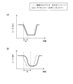
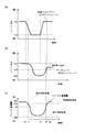
[伝送スループット増大時の入力ビットレートを増大させる制御]
以下、伝送スループット増大時の入力ビットレートを増大させる制御の一例を図9(a)~図9(c)を参照して説明する。
[Control to increase input bit rate when transmission throughput increases]
Hereinafter, an example of control for increasing the input bit rate when the transmission throughput is increased will be described with reference to FIGS. 9 (a) to 9 (c).
時間T3で、伝送路状態の悪化により伝送スループットが低下した状態から伝送路状態の回復に伴い伝送スループットが回復したとする。
Assume that at time T3, the transmission throughput is recovered from the state where the transmission throughput is lowered due to the deterioration of the transmission path state, along with the recovery of the transmission path state.
CPU14の出力ビットレート検出部31は出力ビットレートの値を検出し、バッファ空き容量検出部32はバッファ17のバッファ空き容量22の値を検出し、減少率/増加率演算部33は増加率の値及び減少率の値を算出し、入力ビットレート演算部34は入力ビットレート上限値及び入力ビットレート下限値を算出する(図7のステップS201~ステップS206参照)。ここでは、入力ビットレート決定部35は、現在の入力ビットレートの値が入力ビットレート下限値より小さいとし、入力ビットレート更新値を入力ビットレート下限値に設定する(図7のステップS207、S209、S211参照)。ここでは、入力ビットレート決定部35は、入力ビットレート更新値が最大データレートの値以下であるとし(図7のステップS212参照)、入力ビットレート更新値を再設定することなく入力ビットレート更新値(ここでは、入力ビットレート下限値に等しい値)を符号変換部12に対して通知する(図6のステップS103参照)。これにより、入力ビットレート23の値は出力ビットレート24の値より小さな値で徐々に大きくなる。
The output bit rate detection unit 31 of the CPU 14 detects the value of the output bit rate, the buffer free capacity detection unit 32 detects the value of the buffer free capacity 22 of the buffer 17, and the decrease rate / increase rate calculation unit 33 calculates the increase rate. The input bit rate calculation unit 34 calculates the input bit rate upper limit value and the input bit rate lower limit value (see Step S201 to Step S206 in FIG. 7). Here, the input bit rate determination unit 35 assumes that the current input bit rate value is smaller than the input bit rate lower limit value, and sets the input bit rate update value to the input bit rate lower limit value (steps S207 and S209 in FIG. 7). , S211). Here, the input bit rate determination unit 35 assumes that the input bit rate update value is equal to or less than the maximum data rate value (see step S212 in FIG. 7), and updates the input bit rate without resetting the input bit rate update value. A value (here, a value equal to the input bit rate lower limit value) is notified to the code conversion unit 12 (see step S103 in FIG. 6). As a result, the value of the input bit rate 23 gradually increases with a smaller value than the value of the output bit rate 24.
例えば、増加率設定値がRUP、確保時間がTaであり、時間T4におけるバッファ17のバッファ空き容量22がR4、時間T4における出力ビットレート24がTPAであるとする。時間T4における増加率をTPU4で表わすと、TPU4=(RUP-R4)/Taになる。時間T4における入力ビットレート下限値は時間T4における出力ビットレート24の値(TPA)から時間T4における増加率の値(TPU4)を減算した減算値TPA-TPU4になる。そして、時間T4における入力ビットレート更新値をTP4で表わすと、TP4=TPA-TPU4になる。
For example, it is assumed that the increase rate setting value is RUP, the securing time is Ta, the buffer free capacity 22 of the buffer 17 at time T4 is R4, and the output bit rate 24 at time T4 is TPA. When the rate of increase at time T4 is represented by TPU4, TPU4 = (RUP−R4) / Ta. The input bit rate lower limit value at time T4 is a subtracted value TPA-TPU4 obtained by subtracting the value of the increase rate (TPU4) at time T4 from the value of output bit rate 24 at time T4 (TPA). When the input bit rate update value at time T4 is represented by TP4, TP4 = TPA-TPU4.
時間T3で伝送路状態の悪化が回復して伝送スループット即ちバッファ17から出力されるメディアデータの出力ビットレート24が増大すると、バッファ空き容量22が増加し始める。そして、時間T5でバッファ17のバッファ空き容量22の値が制御開始閾値RTH以上になると、入力ビットレートの値は固定される(図6のステップS101参照)。
When the deterioration of the transmission path state recovers at time T3 and the transmission throughput, that is, the output bit rate 24 of the media data output from the buffer 17, increases, the buffer free space 22 starts to increase. When the value of the buffer free capacity 22 of the buffer 17 becomes equal to or greater than the control start threshold value RTH at time T5, the value of the input bit rate is fixed (see step S101 in FIG. 6).
<入力ビットレートの制御における数値例>
以下、本実施の形態における入力ビットレートの制御における数値例を示す。但し、初期条件として、最大データレートの値を12Mbps、バッファ17の最大蓄積量を500パケット(以下、「Pkt」と記載する。)、制御開始閾値を450Pkt、増加率設定値を500Pkt、減少率設定値を50Pkt、確保時間を500msecとする。但し、1Pktは1500バイトとする。
<Numerical example in input bit rate control>
Hereinafter, numerical examples in the control of the input bit rate in the present embodiment will be shown. However, as initial conditions, the maximum data rate value is 12 Mbps, the maximum accumulation amount of the buffer 17 is 500 packets (hereinafter referred to as “Pkt”), the control start threshold is 450 Pkt, the increase rate set value is 500 Pkt, and the decrease rate The set value is 50 Pkt and the securing time is 500 msec. However, 1 Pkt is 1500 bytes.
[伝送スループット低下時の数値例]
現在の入力ビットレート23の値を12Mbpsとし、伝送路状態の悪化により伝送スループットが12Mbpsから6Mbpsに低下し、バッファ17のバッファ空き容量22が制御開始閾値“450Pkt”を下回ったとする。
[Numerical example when transmission throughput decreases]
Assume that the current value of the input bit rate 23 is 12 Mbps, the transmission throughput drops from 12 Mbps to 6 Mbps due to the deterioration of the transmission path state, and the buffer free capacity 22 of the buffer 17 falls below the control start threshold “450 Pkt”.
CPU14は、減少率及び入力ビットレート上限値を算出する。
CPU 14 calculates the decrease rate and the input bit rate upper limit value.
減少率=(バッファ空き容量-減少率設定値)/確保時間=(450-50)×1500×8/0.5=9.6Mbps
入力ビットレート上限値=出力ビットレート+減少率=6+9.6=15.6Mbps
CPU14は、増加率及び入力ビットレート下限値を算出する。
Decrease rate = (buffer free capacity−decrease rate set value) / reserved time = (450−50) × 1500 × 8 / 0.5 = 9.6 Mbps
Input bit rate upper limit = output bit rate + decrease rate = 6 + 9.6 = 15.6 Mbps
The CPU 14 calculates an increase rate and an input bit rate lower limit value.
増加率=(増加率設定値-バッファ空き容量)/確保時間=(500-450)×1500×8/0.5=1.2Mbps
入力ビットレート下限値=出力ビットレート-増加率=6-1.2=4.8Mbps
CPU14は、現在の入力ビットレート23の値“12Mbps”が入力ビットレート下限値“4.8Mbps”以上入力ビットレート上限値“15.6Mbps”以下であることから、入力ビットレート更新値を現在の入力ビットレート23の値“12Mbps”とする。さらに、CPU14は、入力ビットレート更新値“12Mbps”が最大データレートの値“12Mbps”より大きくないので、入力ビットレート更新値を12Mbpsのままにする。
Increase rate = (Increase rate setting value−buffer free space) / Securing time = (500−450) × 1500 × 8 / 0.5 = 1.2 Mbps
Input bit rate lower limit = output bit rate−increase rate = 6−1.2 = 4.8 Mbps
Since the current value “12 Mbps” of the input bit rate 23 is not less than the input bit rate lower limit value “4.8 Mbps” and not more than the input bit rate upper limit value “15.6 Mbps”, the CPU 14 sets the input bit rate update value to the current value. The value of the input bit rate 23 is “12 Mbps”. Further, since the input bit rate update value “12 Mbps” is not larger than the maximum data rate value “12 Mbps”, the CPU 14 keeps the input bit rate update value at 12 Mbps.
現在の入力ビットレート23の値を12Mbpsとし、伝送路状態の悪化により伝送スループットが6Mbpsになり、バッファ17のバッファ空き容量22が250Pktになったとする。
Suppose that the current input bit rate 23 value is 12 Mbps, the transmission throughput is 6 Mbps due to the deterioration of the transmission path state, and the buffer free space 22 of the buffer 17 is 250 Pkt.
CPU14は、減少率及び入力ビットレート上限値を算出する。
CPU 14 calculates the decrease rate and the input bit rate upper limit value.
減少率=(バッファ空き容量-減少率設定値)/確保時間=(250-50)×1500×8/0.5=4.8Mbps
入力ビットレート上限値=出力ビットレート+減少率=6+4.8=10.8Mbps
CPU14は、増加率及び入力ビットレート下限値を算出する。
Decrease rate = (buffer free capacity−decrease rate set value) / reserved time = (250−50) × 1500 × 8 / 0.5 = 4.8 Mbps
Input bit rate upper limit value = output bit rate + decrease rate = 6 + 4.8 = 10.8 Mbps
The CPU 14 calculates an increase rate and an input bit rate lower limit value.
増加率=(増加率設定値-バッファ空き容量)/確保時間=(500-250)×1500×8/0.5=6Mbps
入力ビットレート下限値=出力ビットレート-増加率=6-6=0Mbps
CPU14は、現在の入力ビットレート23の値“12Mbps”が入力ビットレート上限値“10.8Mbps”より大きいことから、入力ビットレート更新値を入力ビットレート上限値“10.8Mbps”とする。さらに、CPU14は、入力ビットレート更新値“10.8Mbps”が最大データレートの値“12Mbps”より大きくないので、入力ビットレート更新値を10.8Mbpsのままにする。
Increase rate = (Increase rate setting value−buffer free capacity) / Securing time = (500−250) × 1500 × 8 / 0.5 = 6 Mbps
Input bit rate lower limit = output bit rate−increase rate = 6−6 = 0 Mbps
Since the current value “12 Mbps” of the input bit rate 23 is larger than the input bit rate upper limit value “10.8 Mbps”, the CPU 14 sets the input bit rate update value to the input bit rate upper limit value “10.8 Mbps”. Further, since the input bit rate update value “10.8 Mbps” is not larger than the maximum data rate value “12 Mbps”, the CPU 14 keeps the input bit rate update value at 10.8 Mbps.
[伝送スループット回復時の数値例]
現在の入力ビットレート23の値を3Mbpsとし、伝送路状態の回復により伝送スループットが3Mbpsから12Mbpsに増大し、バッファ17のバッファ空き容量22が80Pktを下回ったとする。
[Numeric example when recovering transmission throughput]
Assume that the current value of the input bit rate 23 is 3 Mbps, the transmission throughput increases from 3 Mbps to 12 Mbps due to the recovery of the transmission path state, and the buffer free capacity 22 of the buffer 17 falls below 80 Pkt.
CPU14は、減少率及び入力ビットレート上限値を算出する。
CPU 14 calculates the decrease rate and the input bit rate upper limit value.
減少率=(バッファ空き容量-減少率設定値)/確保時間=(80-50)×1500×8/0.5=0.72Mbps
入力ビットレート上限値=出力ビットレート+減少率=12+0.72=12.72Mbps
CPU14は、増加率及び入力ビットレート下限値を算出する。
Reduction rate = (buffer free capacity−decrease rate setting value) / reservation time = (80-50) × 1500 × 8 / 0.5 = 0.72 Mbps
Input bit rate upper limit = output bit rate + decrease rate = 12 + 0.72 = 12.72 Mbps
The CPU 14 calculates an increase rate and an input bit rate lower limit value.
増加率=(増加率設定値-バッファ空き容量)/確保時間=(500-80)×1500×8/0.5=10.08Mbps
入力ビットレート下限値=出力ビットレート-増加率=12-10.08=1.92Mbps
CPU14は、現在の入力ビットレート23の値“3Mbps”が入力ビットレート下限値“1.92Mbps”以上入力ビットレート上限値“12.72Mbps”以下であることから、入力ビットレート更新値を現在の入力ビットレート23の値“3Mbps”とする。さらに、CPU14は、入力ビットレート更新値“3Mbps”が最大データレートの値“12Mbps”より大きくないので、入力ビットレート更新値を3Mbpsのままにする。
Increase rate = (Increase rate setting value−buffer free space) / Securing time = (500−80) × 1500 × 8 / 0.5 = 10.008 Mbps
Input bit rate lower limit = Output bit rate−Increase rate = 12-10.008 = 1.92 Mbps
Since the current value “3 Mbps” of the input bit rate 23 is not less than the input bit rate lower limit value “1.92 Mbps” and not more than the input bit rate upper limit value “12.72 Mbps”, the CPU 14 sets the input bit rate update value to the current value. The value of the input bit rate 23 is “3 Mbps”. Furthermore, since the input bit rate update value “3 Mbps” is not greater than the maximum data rate value “12 Mbps”, the CPU 14 keeps the input bit rate update value at 3 Mbps.
現在の入力ビットレート23の値を3Mbpsとし、伝送路状態の回復により伝送スループットが12Mbpsになり、バッファ17のバッファ空き容量22が150Pktになったとする。
Suppose that the current input bit rate 23 is 3 Mbps, the transmission throughput is 12 Mbps due to the recovery of the transmission path state, and the buffer free space 22 of the buffer 17 is 150 Pkt.
CPU14は、減少率及び入力ビットレート上限値を算出する。
CPU 14 calculates the decrease rate and the input bit rate upper limit value.
減少率=(バッファ空き容量-減少率設定値)/確保時間=(150-50)×1500×8/0.5=2.4Mbps
入力ビットレート上限値=出力ビットレート+減少率=12+2.4=14.4Mbps
CPU14は、増加率及び入力ビットレート下限値を算出する。
Decrease rate = (buffer free capacity−decrease rate set value) / reserved time = (150−50) × 1500 × 8 / 0.5 = 2.4 Mbps
Input bit rate upper limit = output bit rate + decrease rate = 12 + 2.4 = 14.4 Mbps
The CPU 14 calculates an increase rate and an input bit rate lower limit value.
増加率=(増加率設定値-バッファ空き容量)/確保時間=(500-150)×1500×8/0.5=8.4Mbps
入力ビットレート下限値=出力ビットレート-増加率=12-8.4=3.6Mbps
CPU14は、現在の入力ビットレート23の値“3Mbps”が入力ビットレート下限値“3.6Mbps”より小さいことから、入力ビットレート更新値を入力ビットレート下限値“3.6Mbps”とする。さらに、CPU14は、入力ビットレート更新値“3.6Mbps”が最大データレートの値“12Mbps”より大きくないので、入力ビットレート更新値を3.6Mbpsのままにする。
Increase rate = (Increase rate setting value−buffer free capacity) / Securing time = (500−150) × 1500 × 8 / 0.5 = 8.4 Mbps
Input bit rate lower limit = output bit rate−increase rate = 12−8.4 = 3.6 Mbps
Since the current value “3 Mbps” of the input bit rate 23 is smaller than the input bit rate lower limit value “3.6 Mbps”, the CPU 14 sets the input bit rate update value to the input bit rate lower limit value “3.6 Mbps”. Furthermore, since the input bit rate update value “3.6 Mbps” is not larger than the maximum data rate value “12 Mbps”, the CPU 14 keeps the input bit rate update value at 3.6 Mbps.
<入力ビットレートの低下制御の基本的な考え方>
以下、伝送路スループットの低下時の入力ビットレートを低下させる制御の基本的な考え方の概略について記載する。
<Basic concept of input bit rate reduction control>
Hereinafter, an outline of a basic concept of control for reducing the input bit rate when the transmission path throughput is reduced will be described.
伝送路の状態が悪化して伝送スループット即ちバッファ17から出力されるメディアデータの出力ビットレート24が低下すると、バッファ17のオーバーフローを防ぐために、メディアデータのデータレート即ちバッファ17に入力されるメディアデータの入力ビットレート23が低下するように入力ビットレート23の制御が行われる。
When the transmission path condition deteriorates and the transmission throughput, that is, the output bit rate 24 of the media data output from the buffer 17 decreases, the data rate of the media data, that is, the media data input to the buffer 17, prevents overflow of the buffer 17. The input bit rate 23 is controlled so that the input bit rate 23 decreases.
本実施の形態では、従来技術のように入力ビットレート23の値が出力ビットレート24の値になるように入力ビットレート23を低下させるのではなくて、バッファ17のバッファ空き容量22を利用して入力ビットレート23の値が出力ビットレート24の値より大きくなるように入力ビットレート23の値を低下させる。具体的には、バッファ17のバッファ空き容量22の値が上記の確保時間後に減少率設定値になるような減少率の値を算出し、現在の入力ビットレート23の値が減少率の値と出力ビットレート24の値との加算値(入力ビットレート上限値)より大きければ入力ビットレート23の値が入力ビットレート上限値になるように入力ビットレート23の制御を行う。なお、バッファ17のバッファ空き容量22の値は入力ビットレート23の値と出力ビットレート24の値との差分に応じて増減することから、入力ビットレート23の値が入力ビットレート上限値になるように制御した場合、伝送スループットが変化しない場合であってもバッファ17のバッファ空き容量22は減少率に応じて減少する。
In the present embodiment, the input bit rate 23 is not lowered so that the value of the input bit rate 23 becomes the value of the output bit rate 24 as in the prior art, but the buffer free capacity 22 of the buffer 17 is used. Thus, the value of the input bit rate 23 is lowered so that the value of the input bit rate 23 becomes larger than the value of the output bit rate 24. Specifically, the value of the reduction rate is calculated such that the value of the buffer free capacity 22 of the buffer 17 becomes the reduction rate setting value after the above-described securing time, and the current value of the input bit rate 23 is calculated as the value of the reduction rate. If it is larger than the value added to the value of the output bit rate 24 (input bit rate upper limit value), the input bit rate 23 is controlled so that the value of the input bit rate 23 becomes the input bit rate upper limit value. Note that the value of the buffer free capacity 22 of the buffer 17 increases or decreases in accordance with the difference between the value of the input bit rate 23 and the value of the output bit rate 24, so the value of the input bit rate 23 becomes the input bit rate upper limit value. In such a control, even if the transmission throughput does not change, the buffer free capacity 22 of the buffer 17 decreases according to the decrease rate.
上記の伝送スループットの低下時の入力ビットレートを低下させる制御方法によれば、バッファ17のバッファ空き容量22の値が大きい場合は、出力ビットレート24の値に加算する減算率の値が大きくなり、入力ビットレート上限値が大きくなる。このため、一時的に伝送スループットが低下した場合に入力ビットレート23の値が伝送スループット即ち出力ビットレート24の値になるように入力ビットレートを下げる場合と比較して、入力ビットレートの下げ幅が小さくなり、入力ビットレートの時間的な変動を小さくすることができる。これにより、例えば映像データの配信中に一時的に伝送スループットが低下した場合に、受信側で再生される映像の解像度やフレームレートの下げ幅を小さくすることができ、視聴者は安定した品質の映像を視聴することができる。
According to the control method for reducing the input bit rate when the transmission throughput is reduced, the value of the subtraction rate to be added to the value of the output bit rate 24 increases when the value of the buffer free capacity 22 of the buffer 17 is large. The input bit rate upper limit value becomes large. For this reason, when the transmission bit rate is temporarily lowered, the input bit rate is reduced as compared with the case where the input bit rate is lowered so that the value of the input bit rate 23 becomes the value of the transmission throughput, that is, the output bit rate 24. And the temporal variation of the input bit rate can be reduced. As a result, for example, when the transmission throughput temporarily decreases during the distribution of the video data, it is possible to reduce the amount of reduction in the resolution and frame rate of the video reproduced on the receiving side, and the viewer can achieve stable quality. You can watch the video.
また、バッファ17のバッファ空き容量22の値が小さい場合、出力ビットレートの値に加算する減少率の値が小さくなるが、バッファ17のバッファ空き容量22の値が減少率設定値以下にならない範囲で入力ビットレートの値と出力ビットレートの値との差を小さくする。このため、伝送スループットの低下が一定期間継続することによってバッファ17のバッファ空き容量22の値が小さくなっても、バッファ17のバッファ空き容量22の値は減少率設定値までにしか小さくならずバッファ17のオーバーフローは発生しない。これにより、例えば映像データの送信中に伝送スループットの低下が一定期間継続しても、バッファ17のオーバーフローによりパケットが受信側まで到達せずに失われることを防止し、視聴者は途切れることがない映像を視聴できる。
Further, when the value of the buffer free capacity 22 of the buffer 17 is small, the value of the decrease rate added to the value of the output bit rate is small, but the range in which the value of the buffer free capacity 22 of the buffer 17 does not fall below the decrease rate set value. To reduce the difference between the input bit rate value and the output bit rate value. For this reason, even if the value of the buffer free capacity 22 of the buffer 17 decreases as the transmission throughput continues to decrease for a certain period, the value of the buffer free capacity 22 of the buffer 17 decreases only to the reduction rate setting value. 17 overflow does not occur. As a result, for example, even if a decrease in transmission throughput continues for a certain period during transmission of video data, the packet 17 is prevented from being lost without reaching the receiving side due to overflow of the buffer 17, and the viewer is not interrupted. You can watch the video.
更に、バッファ17のバッファ空き容量22の値が確保時間後に減少率設定値になるようにした場合のバッファ空き容量22の減少率はバッファ17のバッファ空き容量22の値が小さくなるのに伴い徐々に小さくなるので、入力ビットレート23の値を緩やかに小さくすることができる。これにより、例えば映像データの送信中に伝送スループットが低下した場合に、受信側で再生される映像の解像度やフレームレーを緩やかに下げることができ、視聴者が感じる違和感を少なくすることができる。
Furthermore, when the value of the buffer free capacity 22 of the buffer 17 becomes the decrease rate setting value after the securing time, the decrease rate of the buffer free capacity 22 gradually increases as the value of the buffer free capacity 22 of the buffer 17 decreases. Therefore, the value of the input bit rate 23 can be gradually reduced. As a result, for example, when the transmission throughput is reduced during transmission of video data, the resolution and frame rate of the video reproduced on the receiving side can be lowered gradually, and the uncomfortable feeling felt by the viewer can be reduced.
更に、減少率設定値をゼロとすることにより、バッファ17のバッファ空き容量22の値が確保時間後に減少率設定値になるようにした場合のバッファ空き容量22の減少率の値を最大にすることができる。このため、減少率設定値をゼロよりも大きい値にする場合と比べて入力ビットレートの値の下げ幅を最も小さくすることができる。
Further, by setting the decrease rate setting value to zero, the value of the decrease rate of the buffer free space 22 when the value of the buffer free space 22 of the buffer 17 becomes the decrease rate set value after the securing time is maximized. be able to. For this reason, the amount of decrease in the value of the input bit rate can be minimized as compared with the case where the decrease rate setting value is set to a value larger than zero.
<入力ビットレートの増大制御の基本的な考え方>
以下、伝送スループットの増大時の入力ビットレートを増大させる制御の基本的な考え方の概略について記載する。
<Basic concept of input bit rate increase control>
Hereinafter, an outline of a basic concept of control for increasing the input bit rate when the transmission throughput is increased will be described.
伝送路の状態の悪化が回復して伝送スループット即ちバッファ17から出力されるメディアデータの出力ビットレート24が大きくなると、例えば映像データの配信中であれば高画質な映像を視聴者に提供するために、メディアデータのデータレート即ちバッファ17に入力されるメディアデータの入力ビットレート23が増大するように入力ビットレート23の制御が行われる。
When the deterioration of the state of the transmission path is recovered and the transmission throughput, that is, the output bit rate 24 of the media data output from the buffer 17 increases, for example, if video data is being distributed, a high-quality video is provided to the viewer. In addition, the input bit rate 23 is controlled so that the data rate of the media data, that is, the input bit rate 23 of the media data input to the buffer 17 is increased.
本実施の形態では、従来技術のように入力ビットレート23の値が出力ビットレート24の値になるように入力ビットレート23を増大させるのではなくて、バッファ17のバッファ空き容量22を利用して入力ビットレート23の値が出力ビットレート24の値より小さくなるように入力ビットレート23の値を増大させる。具体的には、バッファ17のバッファ空き容量22の値が上記の確保時間後に増加率設定値になるような増加率の値を算出し、現在の入力ビットレート23の値が出力ビットレート24の値から増加率の値を減算した減算値(入力ビットレート下限値)より小さければ入力ビットレート23の値が入力ビットレート下限値になるように入力ビットレート23の制御を行う。なお、バッファ17のバッファ空き容量22の値は入力ビットレート23の値と出力ビットレート24の値との差分に応じて増減することから、入力ビットレート23の値が入力ビットレート下限値になるように制御した場合、伝送スループットが変化しない場合であってもバッファ17のバッファ空き容量22は増加率に応じて増加する。
In this embodiment, the input bit rate 23 is not increased so that the value of the input bit rate 23 becomes the value of the output bit rate 24 as in the prior art, but the buffer free capacity 22 of the buffer 17 is used. Thus, the value of the input bit rate 23 is increased so that the value of the input bit rate 23 becomes smaller than the value of the output bit rate 24. Specifically, the value of the increase rate is calculated such that the value of the buffer free capacity 22 of the buffer 17 becomes the increase rate set value after the above securing time, and the current input bit rate 23 value is the output bit rate 24 value. If the value is smaller than the subtraction value obtained by subtracting the value of the increase rate from the value (input bit rate lower limit value), the input bit rate 23 is controlled so that the value of the input bit rate 23 becomes the input bit rate lower limit value. Note that the value of the buffer free capacity 22 of the buffer 17 increases or decreases according to the difference between the value of the input bit rate 23 and the value of the output bit rate 24, so the value of the input bit rate 23 becomes the input bit rate lower limit value. In such a control, even if the transmission throughput does not change, the buffer free capacity 22 of the buffer 17 increases according to the increase rate.
上記の伝送スループットの増大時の入力ビットレートを増大させる制御方法によれば、バッファ17のバッファ空き容量22の値が確保時間後に減少率設定値より大きい増加率設定値になるようにした場合のバッファ空き容量22の増加率はバッファ17のバッファ空き容量22の値が大きくなるのに伴い徐々に小さくなる。このため、入力ビットレート23の値を緩やかに大きくすることができる。これにより、例えば映像データの送信中に伝送スループットの低下が回復した場合に、受信側で再生される映像の解像度やフレームレートを緩やかに上げることができ、視聴者が感じる違和感を少なくすることができる。
According to the control method for increasing the input bit rate when the transmission throughput is increased, the value of the buffer free capacity 22 of the buffer 17 is set to an increase rate set value larger than the decrease rate set value after the securing time. The increase rate of the buffer free capacity 22 gradually decreases as the value of the buffer free capacity 22 of the buffer 17 increases. For this reason, the value of the input bit rate 23 can be increased gradually. As a result, for example, when a decrease in transmission throughput is recovered during transmission of video data, the resolution and frame rate of the video played back on the receiving side can be increased gradually, reducing the sense of discomfort felt by the viewer. it can.
また、増加率設定値をバッファ17の最大蓄積量とすることにより、伝送スループットが回復した状態が継続した場合のバッファ17のバッファ空き容量22の値を最大にすることができるので、バッファ17の容量を最も有効に利用することができる。
Further, by setting the increase rate setting value as the maximum accumulation amount of the buffer 17, the value of the buffer free capacity 22 of the buffer 17 when the transmission throughput is recovered can be maximized. The capacity can be used most effectively.
<入力ビットレート更新値の決定の基本的な考え方>
以下、入力ビットレート更新値の決定の基本的な考え方の概略について記載する。
<Basic concept for determining the input bit rate update value>
Hereinafter, an outline of the basic concept of determining the input bit rate update value will be described.
無線の伝送路や電灯線の伝送路を用いて通信を行う場合、平均伝送スループットはほぼ一定で安定している状態でも、各時点での伝送スループットは細かく変動している。このため、出力ビットレート24の値が上昇すると常に入力ビットレート23の値を増大させ、出力ビットレート24の値が低下すると常に入力ビットレート23の値を低下させることにすると、入力ビットレート23を低下させる制御と入力ビットレート24を増大させる制御との切り替えが頻繁に発生する。
When performing communication using a wireless transmission line or a power line transmission line, even when the average transmission throughput is almost constant and stable, the transmission throughput at each time point varies finely. Therefore, when the value of the output bit rate 24 is increased, the value of the input bit rate 23 is always increased, and when the value of the output bit rate 24 is decreased, the value of the input bit rate 23 is always decreased. Switching between the control for reducing the control and the control for increasing the input bit rate 24 frequently occurs.
仮に、入力ビットレート23の値が常に出力ビットレート24の値からバッファ空き容量24の増加率の値を減算した値となるように入力ビットレート23を増大させる制御状態から、入力ビットレート23の値が常に出力ビットレート24の値にバッファ空き容量24の減少率の値を加算した値となるように入力ビットレート23を低下させる制御状態に切り替わった場合、入力ビットレート23の値は、出力ビットレート24の値からバッファ空き容量22の増加率の値を減算した値から、出力ビットレート24の値にバッファ空き容量22の減少率の値を加算した値に変化する。つまり、入力ビットレート23の値は、増加率の値と減少率の値とを加算した値分増加し、急激に増加することになる。このため、伝送スループットが低下したタイミングにおいて、クライアント側のAV機器3で再生される映像の解像度やフレームレートが急激に高くなってしまう。
From the control state in which the input bit rate 23 is increased so that the value of the input bit rate 23 is always a value obtained by subtracting the value of the increase rate of the buffer free capacity 24 from the value of the output bit rate 24, the input bit rate 23 When the value is always switched to a control state in which the input bit rate 23 is reduced so that the value is always the value of the output bit rate 24 plus the value of the decrease rate of the buffer free space 24, the value of the input bit rate 23 is A value obtained by subtracting the value of the increase rate of the buffer free space 22 from the value of the bit rate 24 is changed to a value obtained by adding the value of the decrease rate of the buffer free space 22 to the value of the output bit rate 24. That is, the value of the input bit rate 23 increases by a value obtained by adding the increase rate value and the decrease rate value, and increases rapidly. For this reason, at the timing when the transmission throughput is lowered, the resolution and frame rate of the video reproduced by the AV device 3 on the client side are rapidly increased.
これを回避するために、本実施の形態では、伝送スループットが増大して入力ビットレート23を増大させる制御状態から、伝送スループットが低下して入力ビットレートを低下させる制御状態に切り替わった場合、出力ビットレート24の値にバッファ17のバッファ空き容量22の減少率の値を加算した加算値(入力ビットレート上限値)が現在の入力ビットレート23の値よりも大きい間は現在の入力ビットレート23の値を維持するようにしている。
In order to avoid this, in this embodiment, when the control state in which the transmission throughput is increased and the input bit rate 23 is increased is switched to the control state in which the transmission throughput is reduced and the input bit rate is decreased, the output is While the added value (input bit rate upper limit value) obtained by adding the value of the decrease rate of the buffer free capacity 22 of the buffer 17 to the value of the bit rate 24 is larger than the value of the current input bit rate 23, the current input bit rate 23 I try to maintain the value of.
つまり、現在の入力ビットレート23の値が入力ビットレート上限値より大きい場合には入力ビットレート更新値を入力ビットレート上限値とし、現在の入力ビットレート23の値が入力ビットレート上限値以下であれば入力ビットレート更新値を現在の入力ビットレートの値とする。
That is, when the current input bit rate 23 value is larger than the input bit rate upper limit value, the input bit rate update value is set as the input bit rate upper limit value, and the current input bit rate 23 value is less than or equal to the input bit rate upper limit value. If there is, the input bit rate update value is set as the current input bit rate value.
これにより、伝送スループットが回復した状態から再度低下した場合に、入力ビットレート23の値が急激に上がることを防止できるため、入力ビットレート23を安定させることができる。従って、伝送スループットが回復した状態から再度低下した場合に、例えばクライアント側のAV機器3で再生される映像の解像度やフレームレートが急激に上がるということがなくなり、視聴者は安定した品質の映像を視聴することができる。
This makes it possible to prevent the value of the input bit rate 23 from rapidly increasing when the transmission throughput drops again from the recovered state, so that the input bit rate 23 can be stabilized. Therefore, when the transmission throughput drops again from the recovered state, for example, the resolution and frame rate of the video reproduced by the AV device 3 on the client side do not increase suddenly, and the viewer can view the video of stable quality. Can watch.
逆に、入力ビットレート23の値が常に出力ビットレート24の値にバッファ空き容量24の減少率の値を加算した値となるように入力ビットレート23を低下させる制御状態から、入力ビットレート23の値が常に出力ビットレート24の値からバッファ空き容量24の増加率の値を減算した値となるように入力ビットレート23を増大させる制御状態に切り替わった場合、入力ビットレート23の値は、出力ビットレート24の値にバッファ空き容量22の減少率の値を加算した値から、出力ビットレート24の値からバッファ空き容量22の増加率の値を減算した値に変化する。つまり、入力ビットレート23の値は、増加率の値と減少率の値とを加算した値分減少し、急激に減少することになる。このため、伝送スループットが増大したタイミングにおいて、例えばクライアント側のAV機器3で再生される映像の解像度やフレームレートが急激に下がってしまう。
Conversely, from the control state in which the input bit rate 23 is lowered so that the value of the input bit rate 23 is always the value obtained by adding the value of the decrease rate of the buffer free capacity 24 to the value of the output bit rate 24, the input bit rate 23 Is switched to a control state in which the input bit rate 23 is increased so that the value of the output bit rate 24 is always subtracted from the value of the increase rate of the buffer free space 24 from the value of the output bit rate 24, the value of the input bit rate 23 is It changes from the value obtained by adding the value of the decrease rate of the buffer free space 22 to the value of the output bit rate 24 to the value obtained by subtracting the value of the increase rate of the buffer free space 22 from the value of the output bit rate 24. That is, the value of the input bit rate 23 decreases by a value obtained by adding the increase rate value and the decrease rate value, and decreases rapidly. For this reason, at the timing when the transmission throughput is increased, for example, the resolution and frame rate of the video reproduced by the AV device 3 on the client side are drastically lowered.
これを回避するために、本実施の形態では、伝送スループットが低下して入力ビットレート23を低下させる制御状態から、伝送スループットが増大して入力ビットレートを増大させる制御状態に切り替わった場合、出力ビットレート24の値からバッファ17のバッファ空き容量22の増加率の値を減算した減算値(入力ビットレート下限値)が現在の入力ビットレート22の値よりも小さい間は現在の入力ビットレート23の値を維持するようにしている。
In order to avoid this, in the present embodiment, when switching from a control state in which the transmission throughput decreases and the input bit rate 23 decreases to a control state in which the transmission throughput increases and the input bit rate increases, the output is performed. While the subtraction value (input bit rate lower limit value) obtained by subtracting the value of the increase rate of the buffer free space 22 of the buffer 17 from the value of the bit rate 24 is smaller than the current input bit rate 22 value, the current input bit rate 23 I try to maintain the value of.
つまり、現在の入力ビットレート23の値が入力ビットレート下限値より小さい場合には入力ビットレート更新値を入力ビットレート下限値とし、現在の入力ビットレート23の値が入力ビットレート下限値以上であれば入力ビットレート更新値を現在の入力ビットレートの値とする。
That is, if the current input bit rate 23 value is smaller than the input bit rate lower limit value, the input bit rate update value is set as the input bit rate lower limit value, and the current input bit rate 23 value is greater than or equal to the input bit rate lower limit value. If there is, the input bit rate update value is set as the current input bit rate value.
これにより、伝送スループットが低下した状態から回復した場合に、入力ビットレート23の値が急激に下がることを防止できるため、入力ビットレートを安定させることができる。従って、伝送スループットが低下した状態から回復した場合に、例えばクライアント側のAV機器3で再生される映像の解像度やフレームレートが急激に下がるということがなくなり、視聴者は安定した品質の映像を視聴することができる。
Thus, when the transmission throughput is recovered from the lowered state, the value of the input bit rate 23 can be prevented from rapidly decreasing, so that the input bit rate can be stabilized. Therefore, when the transmission throughput is recovered from the lowered state, for example, the resolution and frame rate of the video played back by the AV device 3 on the client side do not drop sharply, and the viewer can watch the video of stable quality. can do.
<従来技術との比較>
本実施の形態の入力ビットレートの制御手法と従来技術の入力ビットレートの制御手法とを図10及び図11を参照しつつ比較する。但し、図10及び図11の各図において、縦軸はレート(bps)を、横軸は時間を表す。
<Comparison with conventional technology>
The input bit rate control method of this embodiment and the conventional input bit rate control method will be compared with reference to FIGS. However, in each figure of FIG.10 and FIG.11, a vertical axis | shaft represents a rate (bps) and a horizontal axis represents time.
図10(a)及び図11(a)は、従来の入力ビットレートの制御手法による、伝送スループット即ちバッファ17から出力されるメディアデータの出力ビットレート24の時間的変動と、送信されるデータのデータレート即ちバッファ17に入力されるメディアデータの入力ビットレート23の時間的変動を示す図である。
FIGS. 10A and 11A show the transmission throughput, that is, the temporal variation of the output bit rate 24 of the media data output from the buffer 17 according to the conventional input bit rate control method, and the transmission data. It is a figure which shows the time change of the input bit rate 23 of the data rate, ie, the media data input into the buffer 17. FIG.
図10(b)及び図11(b)は、本実施の形態の入力ビットレートの制御手法による、伝送スループット即ちバッファ17から出力されるメディアデータの出力ビットレート24の時間的変動と、送信されるデータのデータレート即ちバッファ17に入力されるメディアデータの入力ビットレート23の時間的変動を示す図である。
FIG. 10B and FIG. 11B show the transmission throughput, that is, the temporal variation of the output bit rate 24 of the media data output from the buffer 17 according to the input bit rate control method of this embodiment, and the transmission. FIG. 6 is a diagram showing temporal changes in the data rate of data to be received, that is, the input bit rate 23 of media data input to the buffer 17.
[伝送スループットが瞬間的に低下する場合における両者の比較]
以下、伝送スループットが瞬間的に低下する場合における本実施の形態の入力ビットレートの制御手法と従来技術の入力ビットレートの制御手法とを図10(a),(b)を参照して比較する。
[Comparison of both when transmission throughput drops momentarily]
Hereinafter, the input bit rate control method of the present embodiment and the conventional input bit rate control method in the case where the transmission throughput decreases instantaneously will be compared with reference to FIGS. 10 (a) and 10 (b). .
従来技術の入力ビットレートの制御手法では、図10(a)に示すように、伝送スループットの瞬間的な低下に追従して入力ビットレート23の値が低下する。なお、バッファ17がオーバーフローするのを防ぐために、入力ビットレートの制御を行う時間間隔を短く設定しているものとする。
In the conventional input bit rate control method, as shown in FIG. 10A, the value of the input bit rate 23 decreases following the instantaneous decrease in transmission throughput. It is assumed that the time interval for controlling the input bit rate is set short in order to prevent the buffer 17 from overflowing.
これに対して、本実施の形態の入力ビットレートの制御手法では、図10(b)に示すように、入力ビットレート23を更新する入力ビットレート更新値を、伝送スループット即ち出力ビットレート24の値に減少率の値を加算した値(入力ビットレート上限値)としている。このため、本実施の形態の入力ビットレートの制御手法では、従来技術の入力ビットレートの制御手法と比較して、入力ビットレート24の下げ幅が小さくなり、例えば高画質な映像を視聴者に提供することが可能である。
On the other hand, in the input bit rate control method according to the present embodiment, as shown in FIG. 10B, the input bit rate update value for updating the input bit rate 23 is set to the transmission throughput, that is, the output bit rate 24. The value is obtained by adding the value of the reduction rate to the value (input bit rate upper limit value). For this reason, in the input bit rate control method according to the present embodiment, the amount of decrease in the input bit rate 24 is smaller than that of the conventional input bit rate control method. It is possible to provide.
また、本実施の形態の入力ビットレートの制御手法では、入力ビットレート23を更新する入力ビットレート更新値を、出力ビットレート24の値に減少率の値を加算した値(入力ビットレート上限値)や出力ビットレート24の値から増加率の値を減算した値(入力ビットレート下限値)などとしている。このため、本実施の形態の入力ビットレートの制御手法では、従来技術の入力ビットレートの制御手法と比較して、入力ビットレート23を低下させる場合及び増大させる場合とも、入力ビットレート23が変化する割合が緩やかであり、例えば視聴者に与える視覚的な違和感を小さくすることが可能である。
In the input bit rate control method of this embodiment, the input bit rate update value for updating the input bit rate 23 is a value obtained by adding the value of the reduction rate to the value of the output bit rate 24 (input bit rate upper limit value). ) Or the value obtained by subtracting the value of the increase rate from the value of the output bit rate 24 (input bit rate lower limit value). For this reason, in the input bit rate control method according to the present embodiment, the input bit rate 23 changes both when the input bit rate 23 is decreased and when the input bit rate 23 is increased as compared with the conventional input bit rate control method. For example, it is possible to reduce the visual discomfort given to the viewer.
[伝送スループットの低下幅が大きく、伝送スループットが低下する期間が長い場合における両者の比較]
以下、伝送スループットが低下する幅が大きく、且つ、伝送スループットが低下する期間が長い場合における本実施の形態の入力ビットレートの制御手法と従来技術の入力ビットレートの制御手法とを図11(a),(b)を参照して比較する。
[Comparison of both when the transmission throughput is greatly reduced and the transmission throughput decreases for a long period of time]
Hereinafter, the input bit rate control method according to the present embodiment and the conventional input bit rate control method in the case where the transmission throughput is greatly reduced and the transmission throughput is reduced for a long period are shown in FIG. ) And (b) for comparison.
従来技術の入力ビットレートの制御手法では、図11(a)に示すように、伝送スループットの低下に追従して入力ビットレート23の値が低下する。なお、バッファ17がオーバーフローするのを防ぐために、入力ビットレートの制御を行う時間間隔を短く設定しているものとする。
In the conventional input bit rate control method, the value of the input bit rate 23 decreases as the transmission throughput decreases as shown in FIG. It is assumed that the time interval for controlling the input bit rate is set short in order to prevent the buffer 17 from overflowing.
これに対して、本実施の形態の入力ビットレートの制御手法では、図11(b)に示すように、従来技術の入力ビットレートの制御手法と比較して、入力ビットレートを緩やかに下げて、上げているために例えば視聴者に与える視覚的な違和感を小さくすることが可能である。例えば、入力ビットレート23を下げるのに要する時間を比較すると、従来技術の入力ビットレートの制御手法における時間TA(図11(a)参照)に対して、本実施の形態の入力ビットレートの制御手法における時間TB(図11(b)参照)は長い。このように、本実施の形態の入力ビットレートの制御手法は従来技術の入力ビットレートの制御手法に比べて時間をかけて緩やかに画質を低下させているために、例えば視聴者への視覚的な違和感を低下させることが可能である。
On the other hand, in the input bit rate control method of the present embodiment, as shown in FIG. 11B, the input bit rate is moderately lowered as compared with the conventional input bit rate control method. Therefore, for example, it is possible to reduce the visual discomfort given to the viewer. For example, when the time required to lower the input bit rate 23 is compared, the control of the input bit rate according to the present embodiment is performed with respect to the time TA (see FIG. 11A) in the conventional input bit rate control method. The time TB in the method (see FIG. 11B) is long. As described above, the input bit rate control method according to the present embodiment gradually reduces the image quality over time as compared with the conventional input bit rate control method. It is possible to reduce a sense of incongruity.
≪第2の実施の形態≫
以下、本発明の第2の実施の形態について図面を参照しつつ説明する。
<< Second Embodiment >>
The second embodiment of the present invention will be described below with reference to the drawings.
第1の実施の形態では、サーバ側のAV機器2が入力ビットレート更新値を算出し、バッファ17に入力されるメディアデータのビットレート(データレート)を算出した入力ビットレート更新値に従って変換する。これに対して、第2の実施の形態では、サーバ側のAV機器2に接続された中継装置が入力ビットレート更新値を算出し、バッファ17に入力されるメディアデータのビットレート(データレート)を算出した入力ビットレート更新値に従って変換する。
In the first embodiment, the AV device 2 on the server side calculates the input bit rate update value, and converts the bit rate (data rate) of the media data input to the buffer 17 according to the calculated input bit rate update value. . On the other hand, in the second embodiment, the relay apparatus connected to the server-side AV device 2 calculates the input bit rate update value, and the bit rate (data rate) of the media data input to the buffer 17 Is converted in accordance with the calculated input bit rate update value.
なお、本実施の形態において、第1の実施の形態の構成要素と実質的に同じ構成要素には同じ符号を付し、第1の実施の形態の説明が適用できるため本実施の形態ではその説明を省略し或いは概略を記載するに留める。
In the present embodiment, components that are substantially the same as those in the first embodiment are denoted by the same reference numerals, and the description of the first embodiment can be applied. The explanation is omitted or only an outline is given.
<ネットワーク構成及び動作>
図12は本実施の形態のネットワーク構成図であり、ネットワーク100にはAV機器101,102及び中継装置103,104が含まれている。
<Network configuration and operation>
FIG. 12 is a network configuration diagram of the present embodiment. The network 100 includes AV devices 101 and 102 and relay devices 103 and 104.
本実施の形態では、AV機器101は、メディアデータを送信するサーバ側のAV機器であり、第1の実施の形態のサーバ側のAV機器2と異なり、入力ビットレートの制御を行わない。AV機器102は、他の機器から送信されたメディアデータを受信し、受信したメディアデータを再生、表示するクライアント側のAV機器である。AV機器101は、例えば、通信機能を備えた映像コンテンツデータを記憶可能なHDDレコーダ機器やBlu-ray Disk(登録商標)レコーダ機器などである。AV機器102は、通信機能を備えたテレビなどのディスプレイ装置などである。
In this embodiment, the AV device 101 is a server-side AV device that transmits media data. Unlike the server-side AV device 2 of the first embodiment, the AV device 101 does not control the input bit rate. The AV device 102 is a client-side AV device that receives media data transmitted from another device and reproduces and displays the received media data. The AV device 101 is, for example, an HDD recorder device or a Blu-ray Disk (registered trademark) recorder device capable of storing video content data having a communication function. The AV device 102 is a display device such as a television having a communication function.
中継装置103及び中継装置104は、通信を中継する装置であり、例えば、ゲートウェイ、ルータ、ブリッジ、スイッチングハブなでである。中継装置103は、入力ビットレートの制御を行う。ここでは、中継装置103及び中継装置104は、有線-無線ブリッジとして説明する。
The relay device 103 and the relay device 104 are devices that relay communication, such as gateways, routers, bridges, and switching hubs. The relay apparatus 103 controls the input bit rate. Here, the relay apparatus 103 and the relay apparatus 104 will be described as a wired-wireless bridge.
ネットワーク100では、AV機器101と中継装置103との間の通信及びAV機器102と中継装置104との間の通信は夫々有線通信で実現されており、中継装置103と中継装置104との間の通信は無線通信で実現されている。
In the network 100, communication between the AV device 101 and the relay device 103 and communication between the AV device 102 and the relay device 104 are realized by wired communication, and the communication between the relay device 103 and the relay device 104 is performed. Communication is realized by wireless communication.
AV機器101は例えば蓄積している映像コンテンツデータをストリーミング配信する。AV機器102はストリーミング配信されている映像コンテンツデータを中継装置103及び中継装置104を介して受信し、受信した映像コンテンツデータを再生、表示する。これによって、視聴者はAV機器101に蓄積されている映像コンテンツデータの映像をAV機器102で視聴することができる。
For example, the AV device 101 performs streaming distribution of the stored video content data. The AV device 102 receives the streaming content video content data via the relay device 103 and the relay device 104, and plays back and displays the received video content data. Thus, the viewer can view the video content data stored in the AV device 101 on the AV device 102.
以下、サーバ側のAV機器101に接続された中継装置103の詳細を図面を参照しつつ説明する。なお、AV機器101,102は一般的なAV機器が利用でき、クライアント側に接続された中継装置104は一般的な中継装置が利用でき、詳細な説明を省略する。
Hereinafter, details of the relay apparatus 103 connected to the server side AV device 101 will be described with reference to the drawings. Note that a general AV device can be used for the AV devices 101 and 102, and a general relay device can be used for the relay device 104 connected to the client side, and detailed description thereof is omitted.
<サーバ側のAV機器に接続された中継装置の装置構成>
図13は、図12のサーバ側のAV機器101に接続された中継装置103の装置構成図であり、中継装置103は、符号変換部12と、入力ビットレート制御プログラム16を格納したメモリ13と、CPU14と、バッファ17を備えた通信I/F部15と、通信I/F部111とを備える。但し、中継装置103は、通信I/F部15によって中継装置104に接続され、通信I/F部111によってAV機器101に接続されている。
<Device configuration of relay device connected to AV device on server side>
FIG. 13 is a device configuration diagram of the relay device 103 connected to the server-side AV device 101 of FIG. 12. The relay device 103 includes a code conversion unit 12, a memory 13 storing an input bit rate control program 16, and CPU 14, communication I / F unit 15 including buffer 17, and communication I / F unit 111. However, the relay device 103 is connected to the relay device 104 by the communication I / F unit 15 and is connected to the AV device 101 by the communication I / F unit 111.
通信I/F部111は、ネットワークを介してデータを送受信する機能、例えば、データ信号の変復調やメディアアクセス制御を行う機能を有し、ここでは、有線通信の通信I/F部とする。
The communication I / F unit 111 has a function of transmitting / receiving data via a network, for example, a function of performing modulation / demodulation of a data signal and media access control, and is a communication I / F unit for wired communication here.
例えば、通信I/F部111はAV機器101に記録されたメディアデータをAV機器101から受信する。CPU14はメモリ13に記憶されている入力ビットレート制御プログラム16を実行して入力ビットレート更新値を算出し(図6、図7参照)、符号変換部12は算出された入力ビットレート更新値に従って受信したメディアデータのビットレート(データレート)を変換する。そして、通信I/F部15は符号変換部12による変換により得られたメディアデータをバッファ17に一時的に蓄積しながらネットワークを介して中継装置104へ送信する。中継装置104は、受信したメディアデータをクライアント側のAV機器102へ送出する。
For example, the communication I / F unit 111 receives media data recorded in the AV device 101 from the AV device 101. The CPU 14 executes the input bit rate control program 16 stored in the memory 13 to calculate an input bit rate update value (see FIGS. 6 and 7), and the code conversion unit 12 follows the calculated input bit rate update value. The bit rate (data rate) of received media data is converted. Then, the communication I / F unit 15 transmits the media data obtained by the conversion by the code conversion unit 12 to the relay device 104 via the network while temporarily storing it in the buffer 17. The relay device 104 sends the received media data to the AV device 102 on the client side.
本実施の形態によれば、第1の実施の形態と実質的に同じ効果が得られる。
According to the present embodiment, substantially the same effect as that of the first embodiment can be obtained.
≪第3の実施の形態≫
以下、本発明の第3の実施の形態について図面を参照しつつ説明する。
<< Third Embodiment >>
The third embodiment of the present invention will be described below with reference to the drawings.
第1の実施の形態では、サーバ側のAV機器2が入力ビットレート更新値を算出し、バッファ17に入力されるメディアデータのビットレート(データレート)を算出した入力ビットレート更新値に従って変換する。これに対して、第3の実施の形態では、クライアント側のAV機器がサーバ側のAV機器によって行われるメディアデータのビットレート(データレート)の変換に用いられるデータレート更新値を算出し、算出したデータレート更新値をサーバ側のAV機器へフィードバックし、サーバ側のAV機器はクライアント側のAV機器からフィードバックされたデータレート更新値に従ってメディアデータのビットレート(データレート)を変換する。
In the first embodiment, the AV device 2 on the server side calculates the input bit rate update value, and converts the bit rate (data rate) of the media data input to the buffer 17 according to the calculated input bit rate update value. . On the other hand, in the third embodiment, the client-side AV device calculates the data rate update value used for conversion of the bit rate (data rate) of the media data performed by the server-side AV device. The updated data rate value is fed back to the AV device on the server side, and the AV device on the server side converts the bit rate (data rate) of the media data according to the data rate update value fed back from the AV device on the client side.
なお、本実施の形態において、第1の実施の形態の構成要素と実質的に同じ構成要素には同じ符号を付し、第1の実施の形態の説明が適用できるため本実施の形態ではその説明を省略し或いは概略を記載するに留める。
In the present embodiment, components that are substantially the same as those in the first embodiment are denoted by the same reference numerals, and the description of the first embodiment can be applied. The explanation is omitted or only an outline is given.
<ネットワーク構成及び動作>
図14は本実施の形態のネットワーク構成図であり、ネットワーク500にはAV機器501,502が含まれている。
<Network configuration and operation>
FIG. 14 is a network configuration diagram of the present embodiment, and the network 500 includes AV devices 501 and 502.
本実施の形態では、AV機器501は、メディアデータを記憶保持し、メディアデータを送信するサーバ側のAV機器であり、AV機器502は、他の機器から送信されたメディアデータを受信し、受信したメディアデータを再生、表示するクライアント側のAV機器である。AV機器501は、例えば、通信機能を備えた映像コンテンツデータを記憶可能なHDDレコーダ機器やBlu-ray Disk(登録商標)レコーダ機器などである。AV機器3は、通信機能を備えたテレビなどのディスプレイ装置などである。通信機能として、例えば、第1の実施の形態で列挙したものがあり、図14では通信機能を無線通信で表している。
In this embodiment, the AV device 501 is a server-side AV device that stores and holds media data and transmits media data. The AV device 502 receives and receives media data transmitted from other devices. It is an AV device on the client side that reproduces and displays the media data. The AV device 501 is, for example, an HDD recorder device or a Blu-ray Disk (registered trademark) recorder device that can store video content data having a communication function. The AV device 3 is a display device such as a television having a communication function. Examples of the communication function include those listed in the first embodiment. In FIG. 14, the communication function is represented by wireless communication.
AV機器501は例えば蓄積している映像コンテンツデータをストリーミング配信し、AV機器502はストリーミング配信されている映像コンテンツデータを受信し、受信した映像コンテンツデータを再生、表示する。これによって、視聴者はAV機器501に蓄積されている映像コンテンツデータの映像をAV機器502で視聴することができる。
The AV device 501 performs streaming distribution of the stored video content data, for example, and the AV device 502 receives the streaming content video content data, and reproduces and displays the received video content data. Thus, the viewer can view the video of the video content data stored in the AV device 501 with the AV device 502.
以下、サーバ側のAV機器501及びクライアント側のAV機器502の詳細を図面を参照しつつ説明する。
Hereinafter, details of the AV device 501 on the server side and the AV device 502 on the client side will be described with reference to the drawings.
<AV機器(サーバ側)の装置構成>
図15は図14のサーバ側のAV機器501の装置構成図であり、AV機器501は、メディアデータ記憶部11と、符号変換部12と、メモリ511と、CPU512と、通信I/F部513とを備える。
<Device configuration of AV equipment (server side)>
15 is a device configuration diagram of the server-side AV device 501 of FIG. 14. The AV device 501 includes a media data storage unit 11, a code conversion unit 12, a memory 511, a CPU 512, and a communication I / F unit 513. With.
メモリ511は、例えば、ROMやRAMなどの半導体メモリで構築される。メモリ511は、各種制御プログラムや各種アプリケーションなどのプログラムを記憶保持しており、例えば、クライアント側のAV機器502から送信されたデータレート情報を解析してそれに含まれるデータレート更新値を符号変換部12に対して通知するためのプログラム(以下、「データレート変更プログラム」と言う。)514を記憶保持している。また、メモリ511は、CPU512が動作する際に使用する領域を有する。
The memory 511 is constructed by a semiconductor memory such as a ROM or a RAM, for example. The memory 511 stores and holds programs such as various control programs and various applications. For example, the data rate information transmitted from the client-side AV device 502 is analyzed, and the data rate update value included therein is converted into a code conversion unit. 12, a program (hereinafter referred to as “data rate changing program”) 514 for notifying the terminal 12 is stored. The memory 511 has an area used when the CPU 512 operates.
CPU512は、メモリ511に記憶保持されているプログラムを読み出し、読み出したプログラムを実行することによって、AV機器501全体の各種制御や各種演算を行う機能を有する。例えば、CPU512は、データレート変更プログラム514をメモリ511から読み出して、読み出したデータレート変更プログラム514を実行する。なお、この処理については、図16から図17を参照して後述する。
The CPU 512 has a function of performing various controls and various calculations of the entire AV device 501 by reading a program stored in the memory 511 and executing the read program. For example, the CPU 512 reads the data rate change program 514 from the memory 511 and executes the read data rate change program 514. This process will be described later with reference to FIGS.
通信I/F部513は、ネットワークを介してデータを送受信する機能、例えば、データ信号の変復調やメディアアクセス制御を行う機能を有し、ここでは、無線通信の通信I/F部とする。なお、通信I/F部513は不図示の送信用のバッファを有している。
The communication I / F unit 513 has a function of transmitting and receiving data via a network, for example, a function of performing modulation / demodulation of data signals and media access control. Here, it is a communication I / F unit for wireless communication. The communication I / F unit 513 has a transmission buffer (not shown).
<CPUの機能構成>
図16は図15のCPU512の機能構成図である。但し、図16には、CPU512の機能構成の理解を容易にするため、AV機器501の他の構成要素も図示している。
<Functional configuration of CPU>
FIG. 16 is a functional block diagram of the CPU 512 of FIG. However, FIG. 16 also illustrates other components of the AV device 501 in order to facilitate understanding of the functional configuration of the CPU 512.
CPU512は、メモリ511からそれに記憶保持されているデータレート変更プログラム514を読み出し、読み出したデータレート変更プログラム514を実行する。これによって、CPU512は、レート情報受信解析部531として機能する。
The CPU 512 reads out the data rate changing program 514 stored in the memory 511 and executes the read data rate changing program 514. As a result, the CPU 512 functions as the rate information reception analysis unit 531.
レート情報受信解析部531は、クライアント側のAV機器502から送信されたデータレート情報を通信I/F部513を介して受信し、受信したデータレート情報を解析し、データレート更新値をそれに含まれるデータレート更新値に設定する。レート情報受信解析部531は、データレート更新値が送信すべきメディアデータに設定可能な最大データレートの値以下の場合にはデータレート更新値を変更することなくデータレート更新値を符号変換部12に通知する。一方、レート情報受信解析部531は、データレート更新値が送信すべきメディアデータに設定可能な最大データレートの値より大きい場合にはデータレート更新値を最大データレートの値に再設定し、再設定したデータレート更新値を符号変換部12に通知する。
The rate information reception analysis unit 531 receives the data rate information transmitted from the AV device 502 on the client side via the communication I / F unit 513, analyzes the received data rate information, and includes the data rate update value therein Set to the updated data rate value. The rate information reception analysis unit 531 converts the data rate update value to the code conversion unit 12 without changing the data rate update value when the data rate update value is equal to or less than the value of the maximum data rate that can be set for the media data to be transmitted. Notify On the other hand, if the data rate update value is larger than the maximum data rate value that can be set for the media data to be transmitted, the rate information reception analysis unit 531 resets the data rate update value to the maximum data rate value, The code conversion unit 12 is notified of the set data rate update value.
なお、符号変換部12は、メディアデータ記憶部11に記憶されているメディアデータのビットレート(データレート)をレート情報受信解析部531から通知されたデータレート更新値に従って変換し、変換により得られたメディアデータを通信I/F部513内の不図示のバッファへ出力する。
The code conversion unit 12 converts the bit rate (data rate) of the media data stored in the media data storage unit 11 in accordance with the data rate update value notified from the rate information reception analysis unit 531 and is obtained by the conversion. The media data is output to a buffer (not shown) in the communication I / F unit 513.
<CPUの動作>
図17は図15のCPU512が行うデータレート変更処理の流れを示すフローチャートである。但し、CPU512はメモリ511からそれに記憶されているデータレート変更プログラム514を読み出し、読み出したデータレート変更プログラム514を実行することによって、図17のフローチャートの処理を実行する。
<CPU operation>
FIG. 17 is a flowchart showing the flow of the data rate changing process performed by the CPU 512 of FIG. However, the CPU 512 reads the data rate change program 514 stored in the memory 511 and executes the read data rate change program 514, thereby executing the processing of the flowchart of FIG.
CPU512のレート情報受信解析部531は、クライアント側のAV機器502から通信I/F部513を介してデータレート情報を受信したかを判定する(ステップS301)。レート情報受信解析部531は、データレート情報を受信していないと判定している間(S301:NO)、ステップS301の処理を繰り返す。レート情報受信解析部531は、データレート情報を受信したと判定すると(S301:YES)、受信したデータレート情報を解析し、データレート更新値をそれに含まれるデータレート更新値に設定する(ステップS302)。
The rate information reception analysis unit 531 of the CPU 512 determines whether data rate information has been received from the AV device 502 on the client side via the communication I / F unit 513 (step S301). The rate information reception analysis unit 531 repeats the process of step S301 while determining that the data rate information has not been received (S301: NO). When the rate information reception analysis unit 531 determines that the data rate information has been received (S301: YES), the rate information reception analysis unit 531 analyzes the received data rate information and sets the data rate update value to the data rate update value included therein (step S302). ).
レート情報受信解析部531は、ステップS302で設定したデータレート更新値(受信したデータレート情報に含まれるデータレート更新値)が、送信するメディアデータに設定可能な最大データレートの値より大きいか否かを判定する(ステップS303)。ステップS302で設定されたデータレート更新値が最大データレートの値より大きければ(S303:YES)、レート情報受信解析部531は、データレート更新値を最大データレートの値に再設定し(ステップS304)、ステップS304で再設定したデータレート更新値を符号変換部12に対して通知する(ステップS305)。このようにすることにより、符号変換部12に通知されるデータレート更新値が最大データレートの値を超えることがなくなるため、符号変換部12が最大データレートの値を超えるデータレート更新値に従ってメディアデータのビットレート(データレート)を変換することがなく、メディアデータの変換時のエラー発生を回避することができる。一方、ステップS302で設定されたデータレート更新値が最大データレートの値より大きくなければ(S303:YES)、レート情報受信解析部531は、ステップS302で設定したデータレート更新値を符号変換部12に対して通知する(ステップS305)。なお、ステップS305が行われた後、ステップS301の処理に戻る。
The rate information reception analysis unit 531 determines whether or not the data rate update value set in step S302 (the data rate update value included in the received data rate information) is greater than the maximum data rate value that can be set for the media data to be transmitted. Is determined (step S303). If the data rate update value set in step S302 is larger than the maximum data rate value (S303: YES), the rate information reception analysis unit 531 resets the data rate update value to the maximum data rate value (step S304). ), The data rate update value reset in step S304 is notified to the code converter 12 (step S305). By doing so, the data rate update value notified to the code conversion unit 12 does not exceed the maximum data rate value, so that the code conversion unit 12 can perform media according to the data rate update value exceeding the maximum data rate value. The data bit rate (data rate) is not converted, and an error can be avoided when converting the media data. On the other hand, if the data rate update value set in step S302 is not larger than the maximum data rate value (S303: YES), the rate information reception analysis unit 531 uses the data rate update value set in step S302 as the code conversion unit 12. (Step S305). After step S305 is performed, the process returns to step S301.
符号変換部12は、メディアデータ記憶部11に記憶されているメディアデータのビットレート(データレート)をレート情報受信解析部531から通知を受けたデータレート更新値に従って変換し、変換により得られたメディアデータを通信I/F部513内の不図示のバッファへ出力する。通信I/F部513は不図示のバッファに蓄積されたメディアデータをネットワークを介して例えばクライアント側のAV機器502へ送信する。
The code conversion unit 12 converts the bit rate (data rate) of the media data stored in the media data storage unit 11 according to the data rate update value notified from the rate information reception analysis unit 531 and is obtained by the conversion. Media data is output to a buffer (not shown) in the communication I / F unit 513. The communication I / F unit 513 transmits media data stored in a buffer (not shown) to, for example, the AV device 502 on the client side via the network.
<AV機器(クライアント側)の装置構成>
図18は図14のクライアント側のAV機器502の装置構成図であり、AV機器502は、メモリ551と、CPU552と、通信I/F部553とを備える。
<Device configuration of AV equipment (client side)>
18 is a device configuration diagram of the client-side AV device 502 of FIG. 14. The AV device 502 includes a memory 551, a CPU 552, and a communication I / F unit 553.
メモリ551は、例えば、ROMやRAMなどの半導体メモリで構築される。メモリ551は、各種制御プログラムや各種アプリケーションプログラムなどのプログラムを記憶保持しており、例えば、サーバ側のAV機器501の符号変換部12(図15参照)がメディアデータのビットレート(データレート)の変換に用いるデータレート更新値を決定し、決定したデータレート更新値を例えばサーバ側のAV機器501に対して通知するためのプログラム(以下、「データレート演算プログラム」と言う。)554を記憶保持している。また、メモリ551は、通信I/F部553によって受信されたメディアデータを一時的に記憶保持するバッファ555やCPU552が動作する際に使用する領域を有する。なお、バッファ555については図19を参照して後述する。
The memory 551 is constructed by a semiconductor memory such as a ROM or a RAM, for example. The memory 551 stores and holds programs such as various control programs and various application programs. For example, the code conversion unit 12 (see FIG. 15) of the AV device 501 on the server side sets the bit rate (data rate) of media data. A data rate update value used for conversion is determined, and a program (hereinafter referred to as “data rate calculation program”) 554 for notifying the determined data rate update value to the AV device 501 on the server side is stored and held. is doing. The memory 551 has an area used when the buffer 555 for temporarily storing and holding the media data received by the communication I / F unit 553 and the CPU 552 operate. The buffer 555 will be described later with reference to FIG.
CPU552は、メモリ551に記憶保持されているプログラムを読み出し、読み出したプログラムを実行することによって、AV機器502全体の各種制御や各種演算を行う機能を有する。例えば、CPU552は、データレート演算プログラム554をメモリ551から読み出して、読み出したデータレート演算プログラム554を実行する。なお、この処理については、図20から図23を参照して後述する。
The CPU 552 has a function of performing various controls and various calculations of the entire AV device 502 by reading a program stored in the memory 551 and executing the read program. For example, the CPU 552 reads the data rate calculation program 554 from the memory 551 and executes the read data rate calculation program 554. This process will be described later with reference to FIGS.
通信I/F部553は、ネットワークを介してデータを送受信する機能、例えば、データ信号の変復調やメディアアクセス制御を行う機能を有し、ここでは、無線通信の通信I/F部とする。
The communication I / F unit 553 has a function of transmitting / receiving data via a network, for example, a function of performing modulation / demodulation of a data signal and media access control, and is a wireless communication I / F unit here.
<バッファの構成>
図19は図18のバッファ555の一構成例を説明するための図である。
<Buffer configuration>
FIG. 19 is a diagram for explaining a configuration example of the buffer 555 of FIG.
蓄積量561はバッファ555に蓄積されているデータのデータ量を表し、バッファ空き容量562はバッファ555に蓄積可能な残りのデータのデータ量を表す。データ量の単位は蓄積量561及びバッファ空き容量562ともビット或いはバイト等で表すことができ、本実施の形態ではビットを用いて説明する。
The accumulation amount 561 represents the data amount of data accumulated in the buffer 555, and the buffer free space 562 represents the data amount of remaining data that can be accumulated in the buffer 555. The unit of the data amount can be expressed by bits or bytes or the like for both the accumulation amount 561 and the buffer free space 562, and this embodiment will be described using bits.
入力ビットレート563は、バッファ555に入力されるメディアデータの単位時間当たりのデータ量を表し、出力ビットレート564はバッファ555から出力されるメディアデータの単位時間当たりのデータ量を表す。本実施の形態では、入力ビットレート563及び出力ビットレート564の単位としてbps(bit per second)を用いて説明する。ここでは、入力ビットレート563は通信I/F部553がメディアデータを受信する際の伝送スループットと等しく、出力ビットレート564はサーバ側のAV機器502の符号変換部12(図15参照)から出力されるメディアデータのビットレート(データレート)と等しいとする。
The input bit rate 563 represents the data amount per unit time of the media data input to the buffer 555, and the output bit rate 564 represents the data amount per unit time of the media data output from the buffer 555. In this embodiment, a description will be given using bps (bit per second) as a unit of the input bit rate 563 and the output bit rate 564. Here, the input bit rate 563 is equal to the transmission throughput when the communication I / F unit 553 receives media data, and the output bit rate 564 is output from the code conversion unit 12 of the AV device 502 on the server side (see FIG. 15). It is assumed that it is equal to the bit rate (data rate) of the media data to be processed.
バッファ555は、FIFOの動作原理に従い、入力されたメディアデータを入力された順に出力する。このとき、入力ビットレート563と出力ビットレート564とが等しい場合、バッファ555の蓄積量561は変化しない。入力ビットレート563と出力ビットレート564とが等しくない場合、入力ビットレート563と出力ビットレート564との差分に応じて、バッファ555の蓄積量561は増減する。つまり、入力ビットレート563が出力ビットレート564より大きい場合にはバッファ555の蓄積量561は増加し、入力ビットレート563が出力ビットレート564より小さい場合にはバッファ555の蓄積量561は減少する。
Buffer 555 outputs the input media data in the input order in accordance with the FIFO operation principle. At this time, when the input bit rate 563 and the output bit rate 564 are equal, the accumulation amount 561 of the buffer 555 does not change. When the input bit rate 563 and the output bit rate 564 are not equal, the accumulation amount 561 of the buffer 555 increases or decreases according to the difference between the input bit rate 563 and the output bit rate 564. That is, when the input bit rate 563 is larger than the output bit rate 564, the accumulation amount 561 of the buffer 555 increases, and when the input bit rate 563 is smaller than the output bit rate 564, the accumulation amount 561 of the buffer 555 decreases.
例えば、入力ビットレート563が12Mbpsで出力ビットレート564が8Mbpsの場合、4Mbpsの速度でバッファ555の蓄積量561は増加し、言い換えると、4Mbpsの速度でバッファ555のバッファ空き容量562は減少する。一方、入力ビットレート563が6Mbpsで出力ビットレート564が9Mbpsの場合、3Mbpsの速度でバッファ555の蓄積量561は減少し、言い換えると、3Mbpsの速度でバッファ555のバッファ空き容量562は増加する。
For example, when the input bit rate 563 is 12 Mbps and the output bit rate 564 is 8 Mbps, the storage amount 561 of the buffer 555 increases at a speed of 4 Mbps, in other words, the buffer free capacity 562 of the buffer 555 decreases at a speed of 4 Mbps. On the other hand, when the input bit rate 563 is 6 Mbps and the output bit rate 564 is 9 Mbps, the accumulated amount 561 of the buffer 555 decreases at a speed of 3 Mbps, in other words, the buffer free capacity 562 of the buffer 555 increases at a speed of 3 Mbps.
バッファ555はメディアデータが再生されるまでメディアデータを一時的に保持するものである。バッファ555の蓄積量561がゼロになる、すなわち、バッファアンダーフローが発生すると、再生すべきデータがなくなるため映像や音声の途切れが発生する。本実施の形態では、バッファアンダーフローの発生をできるだけ防止すべく、クライアント側のAV機器502はバッファ555の蓄積量561がある一定量を超えた後にメディアデータの再生を開始するものとする。
The buffer 555 temporarily holds media data until the media data is reproduced. When the accumulation amount 561 of the buffer 555 becomes zero, that is, when a buffer underflow occurs, there is no data to be reproduced, and thus video and audio are interrupted. In this embodiment, in order to prevent the occurrence of buffer underflow as much as possible, it is assumed that the AV device 502 on the client side starts the reproduction of media data after the accumulated amount 561 of the buffer 555 exceeds a certain amount.
<CPUの機能構成>
図20は図18のCPU552の機能構成図である。但し、図20には、CPU552の機能構成の理解を容易にするため、AV機器502の他の構成要素も図示している。
<Functional configuration of CPU>
FIG. 20 is a functional block diagram of the CPU 552 of FIG. However, FIG. 20 also shows other components of the AV device 502 in order to facilitate understanding of the functional configuration of the CPU 552.
CPU552は、メモリ551からそれに記憶保持されているデータレート演算プログラム554を読み出し、読み出したデータレート演算プログラム554を実行する。これによって、CPU552は、伝送スループット検出部571、バッファ蓄積量検出部572、減少率/増加率演算部573、データレート演算部574、データレート決定部575、及びデータレート情報送信制御部576として機能する。
The CPU 552 reads the data rate calculation program 554 stored and held in the memory 551 and executes the read data rate calculation program 554. Thus, the CPU 552 functions as a transmission throughput detection unit 571, a buffer accumulation amount detection unit 572, a decrease rate / increase rate calculation unit 573, a data rate calculation unit 574, a data rate determination unit 575, and a data rate information transmission control unit 576. To do.
伝送スループット検出部571は、バッファ555に入力されるメディアデータの入力ビットレート563の値即ち伝送スループットの値を検出し、検出した入力ビットレート563の値即ち伝送スループットの値をデータレート演算部574へ出力する。
The transmission throughput detecting unit 571 detects the value of the input bit rate 563 of the media data input to the buffer 555, that is, the value of the transmission throughput, and the detected value of the input bit rate 563, that is, the value of the transmission throughput, is the data rate calculating unit 574. Output to.
ここで、伝送スループット検出部571の機能構成について図21を参照しつつ説明する。図21は図20の伝送スループット検出部571の機能構成図である。なお、図21では、伝送スループット検出部571の内部要素とメモリ551及びデータレート演算部574との接続関係を明確にするために、メモリ551及びデータレート演算部574も図示している。
Here, the functional configuration of the transmission throughput detection unit 571 will be described with reference to FIG. FIG. 21 is a functional block diagram of the transmission throughput detector 571 of FIG. FIG. 21 also shows the memory 551 and the data rate calculation unit 574 in order to clarify the connection relationship between the internal elements of the transmission throughput detection unit 571 and the memory 551 and the data rate calculation unit 574.
伝送スループット検出部571は、データレート検出部591、バッファ変化率演算部592、及び伝送スループット演算部593として機能する。
The transmission throughput detection unit 571 functions as a data rate detection unit 591, a buffer change rate calculation unit 592, and a transmission throughput calculation unit 593.
データレート検出部591は、バッファ555から出力されるメディアデータの単位時間当たりのデータ量を検出し、検出結果をバッファ555から出力されるメディアデータの出力ビットレート564の値即ちメディアデータのデータレートの値として伝送スループット演算部593へ出力する。
The data rate detection unit 591 detects the data amount per unit time of the media data output from the buffer 555, and the detection result is the value of the output bit rate 564 of the media data output from the buffer 555, that is, the data rate of the media data. Is output to the transmission throughput calculation unit 593.
バッファ変化率演算部592は、バッファ555の蓄積量561に基づいて、単位時間当たりの蓄積量561の増加や減少を変化率として算出し、算出した変化率の値を伝送スループット演算部593へ出力する。但し、蓄積量561が増加した場合の変化率を正の値で表し、蓄積量561が減少した場合の変化率を負の値で表すことにする。
Based on the accumulated amount 561 of the buffer 555, the buffer change rate calculating unit 592 calculates an increase or decrease in the accumulated amount 561 per unit time as the change rate, and outputs the calculated change rate value to the transmission throughput calculating unit 593. To do. However, the rate of change when the accumulated amount 561 increases is represented by a positive value, and the rate of change when the accumulated amount 561 decreases is represented by a negative value.
伝送スループット演算部593は、データレート検出部591から入力された出力ビットレート564の値即ちデータレートの値からバッファ変化率演算部592から入力された変化率の値を減算することによって入力ビットレート563の値即ち伝送スループットの値を算出し(入力ビットレート=出力ビットレート-変化率;伝送スループット=データレート-変化率)、算出した伝送スループットの値をデータレート演算部574へ出力する。
The transmission throughput calculation unit 593 subtracts the change rate value input from the buffer change rate calculation unit 592 from the value of the output bit rate 564 input from the data rate detection unit 591, that is, the data rate value. The value of 563, that is, the value of transmission throughput is calculated (input bit rate = output bit rate−change rate; transmission throughput = data rate−change rate), and the calculated transmission throughput value is output to the data rate calculation unit 574.
バッファ蓄積量検出部572は、バッファ555の蓄積量561の値を検出し、検出した蓄積量561の値を減少率/増加率演算部573へ出力する。
The buffer accumulation amount detection unit 572 detects the value of the accumulation amount 561 of the buffer 555 and outputs the detected value of the accumulation amount 561 to the decrease rate / increase rate calculation unit 573.
減少率/増加率演算部573は、バッファ蓄積量検出部572から入力されたバッファ555の蓄積量561を利用して、バッファ555の蓄積量561の許容される減少率の値及び増加率の値を算出し、算出した減少率の値及び増加率の値をデータレート演算部574へ出力する。
The decrease rate / increase rate calculation unit 573 uses the accumulation amount 561 of the buffer 555 input from the buffer accumulation amount detection unit 572, and the allowable decrease rate value and the increase rate value of the accumulation amount 561 of the buffer 555. And the calculated decrease rate value and increase rate value are output to the data rate calculation unit 574.
減少率/増加率演算部573は増加率の算出を次のようにして行う。減少率/増加率演算部573は、予め設定された増加率設定値からバッファ555の蓄積量561の値を減算し、減算値を確保時間で除算することによって、増加率の値を算出する(増加率=(増加率設定値-蓄積量)/確保時間)。但し、増加率設定値とは、出力ビットレート564即ちデータレートを制御してバッファ555の蓄積量561の増減を調整し、確保時間後の目標とするバッファ555の蓄積量561の最大値であり、増加率設定値は主として出力ビットレート564即ちデータレートを増大させる制御を行う際に利用される。算出される増加率の値は、確保時間後に増加率設定値までバッファ555の蓄積量561を増加させようとした場合に必要な単位時間当たりのバッファ555の蓄積量561の増加率ということになる。
The decrease rate / increase rate calculation unit 573 calculates the increase rate as follows. The decrease rate / increase rate calculation unit 573 calculates an increase rate value by subtracting the value of the accumulated amount 561 of the buffer 555 from a preset increase rate set value and dividing the subtracted value by the reserved time ( Increase rate = (Increase rate set value−Accumulated amount) / Securing time). However, the increase rate setting value is the maximum value of the accumulation amount 561 of the target buffer 555 after the secured time by adjusting the increase / decrease of the accumulation amount 561 of the buffer 555 by controlling the output bit rate 564, that is, the data rate. The increase rate set value is mainly used when performing control to increase the output bit rate 564, that is, the data rate. The calculated increase rate value is an increase rate of the accumulated amount 561 of the buffer 555 per unit time required to increase the accumulated amount 561 of the buffer 555 to the increase rate set value after the securing time. .
また、減少率/増加率演算部573は減少率の算出を次のようにして行う。減少率/増加率演算部573は、バッファ555の蓄積量561の値から予め設定された減少率設定値を減算し、減算値を確保時間で除算することによって、減少率の値を算出する(減少率=(蓄積量-減少率設定値)/確保時間)。但し、減少率設定値とは、出力ビットレート564即ちデータレートを制御してバッファ555の蓄積量561の増減を調整し、確保時間後の目標とするバッファ555の蓄積量561の最小値であり、減少率設定値は主として出力ビットレート564即ちデータレートを低下させる制御を行う際に利用される。算出される減少率の値は、確保時間後に減少率設定値までバッファ555の蓄積量561を減少させようとした場合に必要な単位時間当たりのバッファ555の蓄積量561の減少率ということになる。
In addition, the decrease rate / increase rate calculation unit 573 calculates the decrease rate as follows. The decrease rate / increase rate calculation unit 573 calculates a decrease rate value by subtracting a preset decrease rate setting value from the value of the accumulation amount 561 of the buffer 555 and dividing the subtracted value by the reserved time ( Reduction rate = (accumulation amount-reduction rate setting value) / securing time). However, the decrease rate set value is the minimum value of the target accumulation amount 561 of the buffer 555 after the secured time by adjusting the increase / decrease of the accumulation amount 561 of the buffer 555 by controlling the output bit rate 564, that is, the data rate. The decrease rate setting value is mainly used when the output bit rate 564, that is, the control for reducing the data rate is performed. The calculated decrease rate value is the decrease rate of the accumulated amount 561 of the buffer 555 per unit time required when the accumulated amount 561 of the buffer 555 is reduced to the decrease rate set value after the securing time. .
但し、増加率設定値は減少率設定値より大きい。増加率設定値は設計時に任意の値にすることができるが、例えば増加率設定値をバッファ555の最大蓄積量としてもよい。減少率設定値は設計時に任意の値にすることができるが、例えば減少率設定値をゼロに設定してもよい。増加率及び減少率の算出に用いる確保時間は設計時に任意の値に設定することができるが、例えば連続的に発生する伝送路誤りの継続時間とすることができる。なお、増加率の算出に用いる確保時間と減少率の算出に用いる確保時間とを同じ値にしてもよいし、異なる値にしてもよい。
However, the increase rate set value is larger than the decrease rate set value. The increase rate setting value can be set to an arbitrary value at the time of design. For example, the increase rate setting value may be the maximum accumulation amount of the buffer 555. Although the reduction rate setting value can be set to an arbitrary value at the time of design, for example, the reduction rate setting value may be set to zero. The securing time used for calculating the increase rate and the decrease rate can be set to an arbitrary value at the time of design, but can be set as, for example, the duration of a transmission path error that occurs continuously. The securing time used for calculating the increase rate and the securing time used for calculating the decrease rate may be the same value or different values.
データレート演算部574は、伝送スループット検出部571から入力された入力ビットレート563の値即ち伝送スループットの値に減少率/増加率演算部573から入力された減少率の値を加算し、加算値をデータレート上限値としてデータレート決定部575へ出力する(データレート上限値=入力ビットレート+減少率;データレート上限値=伝送スループット+減少率)。但し、データレート上限値は、データレート更新値を設定する場合に許容されるデータレートの上限値である。
The data rate calculation unit 574 adds the value of the reduction rate input from the reduction rate / increase rate calculation unit 573 to the value of the input bit rate 563 input from the transmission throughput detection unit 571, that is, the value of the transmission throughput. Is output to the data rate determining unit 575 as a data rate upper limit value (data rate upper limit value = input bit rate + decrease rate; data rate upper limit value = transmission throughput + decrease rate). However, the data rate upper limit value is an upper limit value of the data rate that is allowed when the data rate update value is set.
また、データレート演算部574は、伝送スループット検出部571から入力された入力ビットレート563の値即ち伝送スループットの値から減少率/増加率演算部573から入力された増加率の値を減算し、減算値をデータレート下限値としてデータレート決定部575へ出力する(データレート下限値=入力ビットレート-増加率;データレート下限値=伝送スループット-増加率)。但し、データレート下限値は、データレート更新値を設定する場合に許容されるデータレートの下限値である。
Further, the data rate calculation unit 574 subtracts the value of the increase rate input from the decrease rate / increase rate calculation unit 573 from the value of the input bit rate 563 input from the transmission throughput detection unit 571, that is, the value of the transmission throughput, The subtraction value is output to data rate determining section 575 as the data rate lower limit value (data rate lower limit value = input bit rate−increase rate; data rate lower limit value = transmission throughput−increase rate). However, the data rate lower limit value is a lower limit value of the data rate that is allowed when the data rate update value is set.
データレート決定部575は、図21のデータレート検出部591で検出される現在のデータレートの値と、データレート演算部574から入力されるデータレート上限値及びデータレート下限値とに基づいて、データレート更新値を決定し、決定したデータレート更新値をデータレート情報送信制御部576へ出力する。
The data rate determining unit 575 is based on the current data rate value detected by the data rate detecting unit 591 in FIG. 21 and the data rate upper limit value and data rate lower limit value input from the data rate calculating unit 574. The data rate update value is determined, and the determined data rate update value is output to the data rate information transmission control unit 576.
詳述すれば、データレート決定部575は、現在のデータレートの値がデータレート下限値以上データレート上限値以下であれば、データレート更新値を現在のデータレートの値に設定する。データレート決定部575は、現在のデータレートの値がデータレート下限値より小さければ、データレート更新値をデータレート下限値に設定し、現在のデータレートの値がデータレート上限値より大きければ、データレート更新値をデータレート上限値に設定する。
More specifically, if the current data rate value is not less than the data rate lower limit value and not more than the data rate upper limit value, the data rate determining unit 575 sets the data rate update value to the current data rate value. The data rate determining unit 575 sets the data rate update value to the data rate lower limit value if the current data rate value is smaller than the data rate lower limit value, and if the current data rate value is larger than the data rate upper limit value, Set the data rate update value to the upper limit of the data rate.
データレート情報送信制御部576は、データレート決定部575から入力されたデータレート更新値を含むデータレート情報を通信I/F部553へ出力する。データレート情報は通信I/F部553から例えばサーバ側のAV機器501へ送信される。
Data rate information transmission control section 576 outputs data rate information including the data rate update value input from data rate determination section 575 to communication I / F section 553. The data rate information is transmitted from the communication I / F unit 553 to the AV device 501 on the server side, for example.
図20及び図21を用いて説明したCPU552の構成によれば、バッファ555の蓄積量561、出力ビットレート564、及びバッファ555の蓄積量561の変化率というバッファ555の状態を検出するだけで、サーバ側のAV機器501の符号変換部12によるメディアデータのデータレートの変換を制御することができる。このため、データレートの変換の制御が容易になり、AV機器502の構成を簡略化することができる。
According to the configuration of the CPU 552 described with reference to FIGS. 20 and 21, only by detecting the state of the buffer 555 such as the accumulation amount 561 of the buffer 555, the output bit rate 564, and the rate of change of the accumulation amount 561 of the buffer 555, The conversion of the data rate of the media data by the code conversion unit 12 of the AV device 501 on the server side can be controlled. For this reason, control of data rate conversion is facilitated, and the configuration of the AV device 502 can be simplified.
<CPUの動作>
図22は図18のCPU552が行うデータレート演算処理の流れを示すフローチャートである。但し、CPU552はメモリ551からそれに記憶されているデータレート演算プログラム554を読み出し、読み出したデータレート演算プログラム554を実行することによって、図22及び後述する図23のフローチャートの処理を実行する。
<CPU operation>
FIG. 22 is a flowchart showing the flow of data rate calculation processing performed by the CPU 552 of FIG. However, the CPU 552 reads the data rate calculation program 554 stored in the memory 551 and executes the read data rate calculation program 554, thereby executing the processing of the flowchart of FIG.
CPU552は、バッファ555の蓄積量561の値が予め設定された制御開始閾値より小さいかを判定する(ステップS501)。
The CPU 552 determines whether the value of the accumulation amount 561 of the buffer 555 is smaller than a preset control start threshold (step S501).
バッファ555の蓄積量561の値が制御開始閾値以上である間(S501:NO)、ステップS501の処理が繰り返し行われ、データレートの演算処理は行われない。例えば、蓄積量561の値が制御開始閾値より小さくなるまで、伝送スループットが安定していると判断し、データレートの更新が行われない。また、伝送路の状態が回復して蓄積量561の値が制御開始閾値以上になってから再度蓄積量561の値が制御開始閾値よりも小さくなるまで、伝送スループットが安定していると判断し、データレートの値は蓄積量561の値が制御開始閾値以上になった時点のデータレートの値で固定される。このように、バッファ555の蓄積量561の値が制御開始閾値以上にある場合は伝送スループットが安定していると判断し、伝送スループットが安定している場合におけるバッファ555の蓄積量561の瞬時的な変動に対してデータレートの更新は行われない。このため、伝送スループットが安定した状態ではデータレートが一定値に保たれる。これにより、例えば映像データの送信時に、伝送スループットが安定した状態ではクライアント側のAV機器3で再生される映像の解像度が下がったりフレームレートが低くなったりする変化が発生せず、視聴者は違和感なく映像を視聴することができる。
While the value of the accumulation amount 561 of the buffer 555 is equal to or greater than the control start threshold (S501: NO), the process of step S501 is repeatedly performed, and the data rate calculation process is not performed. For example, it is determined that the transmission throughput is stable until the value of the accumulation amount 561 becomes smaller than the control start threshold, and the data rate is not updated. Further, it is determined that the transmission throughput is stable until the value of the accumulation amount 561 becomes equal to or greater than the control start threshold value after the transmission path state is recovered until the value of the accumulation amount 561 becomes smaller than the control start threshold value again. The data rate value is fixed at the data rate value when the accumulated amount 561 is equal to or greater than the control start threshold value. Thus, when the value of the accumulation amount 561 of the buffer 555 is equal to or greater than the control start threshold value, it is determined that the transmission throughput is stable, and the accumulation amount 561 of the buffer 555 is instantaneous when the transmission throughput is stable. The data rate is not updated for any fluctuations. For this reason, the data rate is kept constant when the transmission throughput is stable. As a result, for example, when transmitting video data, when the transmission throughput is stable, there is no change in the resolution of the video reproduced by the AV device 3 on the client side or the frame rate is lowered, and the viewer feels uncomfortable. You can watch the video without
一方、バッファ555の蓄積量561の値が制御開始閾値より小さいと判定された場合(S501:YES)、CPU552は、図23に処理の流れを示すデータレート更新値決定処理を実行することによってデータレート更新値を決定する(ステップS502)。CPU552のデータレート情報送信制御部576は、ステップS502の処理で決定されたデータレート更新値を含むデータレート情報を通信I/F部553へ出力し(ステップS503)、ステップS501の処理が行われる。通信I/F部553はデータレート情報送信制御部576から入力されたデータレート情報をネットワークを介して例えばサーバ側のAV機器501へ送信する。
On the other hand, when it is determined that the value of the accumulation amount 561 in the buffer 555 is smaller than the control start threshold (S501: YES), the CPU 552 executes the data rate update value determination process whose process flow is shown in FIG. A rate update value is determined (step S502). The data rate information transmission control unit 576 of the CPU 552 outputs data rate information including the data rate update value determined in the process of step S502 to the communication I / F unit 553 (step S503), and the process of step S501 is performed. . The communication I / F unit 553 transmits the data rate information input from the data rate information transmission control unit 576 to, for example, the server-side AV device 501 via the network.
[データレート更新値決定処理]
図23は図22のデータレート更新値決定処理(ステップS502)の流れを示すフローチャートである。
[Data rate update value decision processing]
FIG. 23 is a flowchart showing the flow of the data rate update value determination process (step S502) of FIG.
伝送スループット検出部571において、データレート検出部591はバッファ555から出力されるメディアデータの出力ビットレート594の値即ちメディアデータのデータレートの値を検出し、バッファ変化率演算部592はバッファ555の蓄積量561の変化率の値を算出する。そして、伝送スループット演算部593は検出された出力ビットレート564の値即ちデータレートの値から算出された変化率の値を減算することによって入力ビットレート563の値即ち伝送スループットの値を算出する(ステップS601)。
In the transmission throughput detection unit 571, the data rate detection unit 591 detects the value of the output bit rate 594 of the media data output from the buffer 555, that is, the value of the data rate of the media data, and the buffer change rate calculation unit 592 A change rate value of the accumulation amount 561 is calculated. Then, the transmission throughput calculation unit 593 calculates the value of the input bit rate 563, that is, the value of the transmission throughput by subtracting the value of the calculated change rate from the value of the detected output bit rate 564, that is, the data rate. Step S601).
バッファ蓄積量検出部572はバッファ555の蓄積量561の値を検出する(ステップS602)。減少率/増加率演算部573は、増加率設定値からステップS602で検出されたバッファ555の蓄積量561の値を減算し、減算値を確保時間で除算することによって、増加率の値を算出する(ステップS603)。また、減少率/増加率演算部573は、ステップS602で検出されたバッファ555の蓄積量561の値から減少率設定値を減算し、減算値を確保時間で除算することによって、減少率の値を算出する(ステップS604)。
The buffer accumulation amount detection unit 572 detects the value of the accumulation amount 561 of the buffer 555 (step S602). The decrease rate / increase rate calculation unit 573 calculates the value of the increase rate by subtracting the accumulated amount 561 of the buffer 555 detected in step S602 from the increase rate set value and dividing the subtracted value by the reserved time. (Step S603). Further, the decrease rate / increase rate calculation unit 573 subtracts the decrease rate set value from the value of the accumulation amount 561 of the buffer 555 detected in step S602, and divides the subtraction value by the reserved time, thereby obtaining the value of the decrease rate. Is calculated (step S604).
データレート演算部574は、ステップS601で検出された伝送スループットの値にステップS604で算出された減少率の値を加算し、加算値をデータレート上限値とする(ステップS605)。また、データレート演算部574は、ステップS601で検出された伝送スループットの値からステップS603で算出された増加率の値を減算し、減算値をデータレート下限値とする(ステップS606)。
The data rate calculation unit 574 adds the value of the decrease rate calculated in step S604 to the transmission throughput value detected in step S601, and sets the added value as the data rate upper limit value (step S605). Further, the data rate calculation unit 574 subtracts the increase rate value calculated in step S603 from the transmission throughput value detected in step S601, and sets the subtraction value as the data rate lower limit value (step S606).
データレート決定部575は、現在のデータレートの値がステップS606で得られたデータレート下限値以上ステップS605で得られたデータレート上限値以下の範囲内であるかを判定する(ステップS607)。
The data rate determination unit 575 determines whether the current data rate value is within the range of the data rate lower limit value obtained in step S606 and less than or equal to the data rate upper limit value obtained in step S605 (step S607).
現在のデータレートの値がその範囲内であれば(S607:YES)、データレート決定部575は、データレート更新値を現在のデータレートの値に設定し(ステップS608)、図22のステップS503が行われる。このようにすることにより、伝送スループットが回復した状態から再度低下した場合や伝送スループットが低下した状態から回復した場合に、現在のデータレートの値がデータレート下限値以上データレート上限値以下の範囲内であればデータレートの更新が行われない。このため、現在のデータレートの値が上記の範囲内にあれば伝送スループットが変動してもデータレートは変動することなく安定する。これにより、例えばクライアント側のAV機器502で再生される映像の解像度やフレームレートが急激に上がったり下がったりするような状況を回避でき、視聴者は安定した品質の映像を視聴することができる。
If the current data rate value is within the range (S607: YES), the data rate determining unit 575 sets the data rate update value to the current data rate value (step S608), and step S503 in FIG. Is done. In this way, when the transmission throughput drops again from the recovered state, or when recovering from the reduced transmission throughput, the current data rate value is in the range between the data rate lower limit value and the data rate upper limit value. If it is within, the data rate is not updated. For this reason, if the value of the current data rate is within the above range, the data rate is stable without changing even if the transmission throughput changes. As a result, for example, it is possible to avoid a situation in which the resolution or frame rate of the video played back by the AV device 502 on the client side suddenly increases or decreases, and the viewer can view videos of stable quality.
一方、現在のデータレートの値がその範囲内になければ(S607:NO)、データレート決定部575は、現在のデータレートの値がデータレート上限値より大きいかを判定する(ステップS609)。
On the other hand, if the current data rate value is not within the range (S607: NO), the data rate determining unit 575 determines whether the current data rate value is larger than the data rate upper limit value (step S609).
現在のデータレートの値がデータレート上限値より大きければ(S609:YES)、バッファ555の蓄積量561が減少してデータレート上限値が現在のデータレートの値より低下した状況であることから、データレート決定部575は、データレートを下げるべく、データレート更新値をデータレート上限値に設定し(ステップS610)、図22のステップS503の処理が行われる。
If the current data rate value is larger than the data rate upper limit value (S609: YES), the accumulated amount 561 of the buffer 555 is reduced and the data rate upper limit value is lower than the current data rate value. The data rate determining unit 575 sets the data rate update value to the data rate upper limit value in order to lower the data rate (step S610), and the process of step S503 in FIG. 22 is performed.
一方、現在のデータレートの値がデータレート上限値より大きくなければ、つまり、現在のデータレートの値がデータレート下限値より小さければ(S609:NO)、バッファ555の蓄積量561が増加してデータレート下限値が現在のデータレートの値より大きくなった状況であることから、データレート決定部575は、データレートを上げるべく、データレート更新値をデータレート下限値に設定し(ステップS611)、図22のステップS503の処理が行われる。
On the other hand, if the current data rate value is not larger than the data rate upper limit value, that is, if the current data rate value is smaller than the data rate lower limit value (S609: NO), the accumulated amount 561 of the buffer 555 increases. Since the data rate lower limit value is larger than the current data rate value, the data rate determining unit 575 sets the data rate update value to the data rate lower limit value in order to increase the data rate (step S611). The process of step S503 in FIG. 22 is performed.
<データレート更新のシーケンス例>
図24はサーバ側のAV機器501からクライアント側のAV機器502へデータストリームを配信する場合のシーケンス図である。
<Example of data rate update sequence>
FIG. 24 is a sequence diagram when a data stream is distributed from the server-side AV device 501 to the client-side AV device 502.
サーバ側のAV機器501では、符号変換部12はメディアデータ記憶部11に記憶されている映像データのビットレート(データレート)を変換し、この変換によって得られた映像データは通信I/F部513を介してストリーム配信される。クライアント側のAV機器502は、ストリーム配信されている映像データを通信I/F部553で受信し、受信した映像データをメモリ551のバッファ555に蓄積しながら順次再生する(ステップS701)。
In the AV apparatus 501 on the server side, the code conversion unit 12 converts the bit rate (data rate) of the video data stored in the media data storage unit 11, and the video data obtained by this conversion is converted into the communication I / F unit. Streamed via 513. The AV device 502 on the client side receives the streamed video data by the communication I / F unit 553, and sequentially plays back the received video data while accumulating it in the buffer 555 of the memory 551 (step S701).
このとき、クライアント側のAV機器502では、CPU552はデータレート演算プログラム554をメモリ551から読み出して実行することによって(図22、図23参照)、データレート更新値を算出し(ステップS702)、算出したデータレート更新値を含むデータレート情報を通信I/F部553を介してAV機器501へ送信する(ステップS703)。
At this time, in the client AV device 502, the CPU 552 reads the data rate calculation program 554 from the memory 551 and executes it (see FIGS. 22 and 23), thereby calculating the data rate update value (step S702). The data rate information including the updated data rate value is transmitted to the AV device 501 via the communication I / F unit 553 (step S703).
サーバ側のAV機器501では、CPU512はデータレート変更プログラム514をメモリ511から読み出して実行することによって(図17参照)、データレート情報に含まれるデータレート更新値と最大データレートの値とを用いてデータレート更新値を決定する(ステップS704)。符号変換部12はメディアデータ記憶部11に記憶されている映像データのビットレート(データレート)を決定されたデータレート更新値に従って変換する(ステップS705)。符号変換部12による変換によって得られた映像データは通信I/F部513を介してストリーム配信される。クライアント側のAV機器502は、ストリーム配信されている映像データを通信I/F部553で受信し、受信した映像データをメモリ551のバッファ555に蓄積しながら順次再生する(ステップS706)。
In the server-side AV device 501, the CPU 512 reads the data rate change program 514 from the memory 511 and executes it (see FIG. 17), thereby using the data rate update value and the maximum data rate value included in the data rate information. The data rate update value is determined (step S704). The code conversion unit 12 converts the bit rate (data rate) of the video data stored in the media data storage unit 11 according to the determined data rate update value (step S705). Video data obtained by the conversion by the code conversion unit 12 is stream-distributed via the communication I / F unit 513. The AV device 502 on the client side receives the video data distributed in the stream by the communication I / F unit 553, and sequentially reproduces the received video data while accumulating it in the buffer 555 of the memory 551 (step S706).
これによって、映像データのデータレートはリアルタイムに変換されて、バッファ555のアンダーフローを防ぎ、映像の途切れを防ぐことが可能になる。
This allows the data rate of the video data to be converted in real time, preventing the buffer 555 from underflowing and preventing the video from being interrupted.
<データレートの制御例>
出力ビットレート564即ちデータレートの制御の一例として、伝送スループットが低下し、一定時間後に伝送スループットが回復する状況におけるバッファ555から出力されるメディアデータの出力ビットレート即ちメディアデータのデータレートの制御について図25及び図26を参照しつつ説明する。
<Example of data rate control>
As an example of the control of the output bit rate 564, that is, the data rate, the control of the output bit rate of the media data that is output from the buffer 555, that is, the data rate of the media data in the situation where the transmission throughput is reduced and the transmission throughput is recovered after a certain time. This will be described with reference to FIGS. 25 and 26. FIG.
図25(a)及び図26(a)は、伝送スループット即ちバッファ555に入力されるメディアデータの入力ビットレート563の時間的変動を示す図であり、縦軸はレート(bps)を、横軸は時間を表す。図25(a)及び図26(a)では、時間t0で伝送路の状態の悪化が発生して伝送スループットが急激に下がり始め、一定時間後の時間t3で伝送路の状態が回復して伝送スループットが急激に上がり始めている様子が示されている。
FIG. 25A and FIG. 26A are diagrams showing temporal variations in transmission throughput, that is, the input bit rate 563 of media data input to the buffer 555, where the vertical axis indicates the rate (bps) and the horizontal axis Represents time. 25 (a) and 26 (a), the transmission path state deteriorates at time t0 and the transmission throughput starts to drop sharply, and the transmission path state recovers at time t3 after a certain period of time for transmission. It shows how the throughput is starting to rise sharply.
図25(b)及び図26(b)は、受信されるメディアデータのデータレート即ちバッファ555から出力されるメディアデータの出力ビットレート564の時間的な変動を示す図であり、縦軸はレート(bps)を、横軸は時間を表す。
FIG. 25B and FIG. 26B are diagrams showing temporal fluctuations in the data rate of received media data, that is, the output bit rate 564 of media data output from the buffer 555, and the vertical axis indicates the rate. (Bps), the horizontal axis represents time.
図25(c)及び図26(c)は、バッファ555の蓄積量561の時間的な変動を示す図であり、縦軸はバッファの蓄積量を、横軸は時間を表す。
FIG. 25 (c) and FIG. 26 (c) are diagrams showing temporal fluctuations of the accumulation amount 561 of the buffer 555, where the vertical axis represents the buffer accumulation amount and the horizontal axis represents time.
[伝送スループット低下時のデータレートを低下させる制御]
以下、伝送スループット低下時の出力ビットレート564即ちデータレートを低下させる制御の一例を図25(a)~図25(c)を参照して説明する。
[Control to reduce data rate when transmission throughput decreases]
Hereinafter, an example of control for reducing the output bit rate 564, that is, the data rate when the transmission throughput is reduced will be described with reference to FIGS. 25 (a) to 25 (c).
時間t0で、伝送路状態が悪化して伝送スループット即ちバッファ555に入力されるメディアデータの入力ビットレート563が低下し始め、入力ビットレート563の値がtpaからtpbまで低下する。この入力ビットレート563の低下に伴い、バッファ555の蓄積量561が減少する。そして、時間t1まではバッファ555の蓄積量561の値が制御開始閾値dth以上なので、出力ビットレート564の値即ちデータレートの値はそのままである(図22のステップS501参照)。このように、蓄積量561の値が制御開始閾値dth以上の間は、伝送スループットの値が低下しても出力ビットレート564の値即ちデータレートの値は低下しない。
At time t0, the transmission path condition deteriorates and the transmission throughput, that is, the input bit rate 563 of the media data input to the buffer 555 starts to decrease, and the value of the input bit rate 563 decreases from tpa to tpb. As the input bit rate 563 decreases, the accumulation amount 561 of the buffer 555 decreases. Since the value of the accumulation amount 561 of the buffer 555 is equal to or greater than the control start threshold value dth until time t1, the value of the output bit rate 564, that is, the value of the data rate remains unchanged (see step S501 in FIG. 22). As described above, while the value of the accumulation amount 561 is equal to or greater than the control start threshold dth, the value of the output bit rate 564, that is, the value of the data rate does not decrease even if the transmission throughput value decreases.
バッファ555の蓄積量561の値は、入力ビットレート563の値と出力ビットレート564の値との差分に応じて減少し、時間t1でバッファ555の蓄積量561の値が制御開始閾値dthを下回ったとする。CPU552はデータレート更新値の決定及びサーバ側のAV機器501に対する決定したデータレート更新値を含むデータレート情報の送信を開始し、バッファ555の蓄積量561の値が制御開始閾値dth以上になるまで、データレート更新値の決定及びサーバ側のAV機器501に対する決定したデータレート更新値を含むデータレート情報の送信を行う(図22参照)。
The value of the accumulation amount 561 of the buffer 555 decreases according to the difference between the value of the input bit rate 563 and the value of the output bit rate 564, and the value of the accumulation amount 561 of the buffer 555 falls below the control start threshold value dth at time t1. Suppose. The CPU 552 starts the determination of the data rate update value and the transmission of the data rate information including the determined data rate update value to the server-side AV device 501 until the value of the accumulation amount 561 in the buffer 555 becomes equal to or greater than the control start threshold value dth. Then, the data rate update value is determined, and data rate information including the determined data rate update value is transmitted to the AV device 501 on the server side (see FIG. 22).
CPU552の伝送スループット検出部571は入力ビットレート563の値即ち伝送スループットの値を検出し、バッファ蓄積量検出部572はバッファ555の蓄積量561の値を検出し、減少率/増加率演算部573は増加率の値及び減少率の値を算出し、データレート演算部574はデータレート上限値及びデータレート下限値を算出する(図23のステップS601~ステップS606参照)。ここでは、データレート決定部575は、現在のデータレートの値がデータレート上限値より大きいとし、データレート更新値をデータレート上限値に設定し、データレート情報送信制御部576はデータレート更新値を含むデータレート情報を通信I/F部553へ出力する(図23のステップS607、S609、S610、図22のステップS503参照)。これにより、データレートの値は伝送スループットの値より大きな値で徐々に小さくなる。
The transmission throughput detection unit 571 of the CPU 552 detects the value of the input bit rate 563, that is, the value of the transmission throughput, and the buffer accumulation amount detection unit 572 detects the value of the accumulation amount 561 of the buffer 555, and the decrease rate / increase rate calculation unit 573. Calculates an increase rate value and a decrease rate value, and the data rate calculation unit 574 calculates a data rate upper limit value and a data rate lower limit value (see steps S601 to S606 in FIG. 23). Here, the data rate determining unit 575 sets the current data rate value to be larger than the data rate upper limit value, sets the data rate update value to the data rate upper limit value, and the data rate information transmission control unit 576 sets the data rate update value. Is output to the communication I / F unit 553 (see steps S607, S609, S610 in FIG. 23, and step S503 in FIG. 22). Thereby, the value of the data rate is gradually decreased with a value larger than the value of the transmission throughput.
例えば、減少率設定値がddw、確保時間がtaであり、時間t2におけるバッファ555の蓄積量561がd2、時間t2における入力ビットレート563即ち伝送スループットがtpbであるとする。時間t2における減少率をtpd2で表わすと、tpd2=(d2-ddw)/taになる。時間t2におけるデータレート上限値は時間t2における伝送スループットの値(tpb)に時間t2における減算率の値(tpd2)を加算した加算値tpb+tpd2になる。そして、時間t2におけるデータレート更新値をtp2で表わすと、tp2=tpb+tpd2になる。
For example, assume that the reduction rate setting value is ddw, the securing time is ta, the accumulated amount 561 of the buffer 555 at time t2 is d2, and the input bit rate 563 at time t2, that is, the transmission throughput is tpb. When the rate of decrease at time t2 is represented by tpd2, tpd2 = (d2-ddw) / ta. The upper limit of the data rate at time t2 is an addition value tpb + tpd2 obtained by adding the value of the subtraction rate (tpd2) at time t2 to the transmission throughput value (tpb) at time t2. When the data rate update value at time t2 is expressed as tp2, tp2 = tpb + tpd2.
[伝送スループット増大時のデータレートを増大させる制御]
以下、伝送スループット増大時の出力ビットレート564即ちデータレートを増大させる制御の一例を図26(a)~図26(c)を参照して説明する。
[Control to increase data rate when transmission throughput increases]
Hereinafter, an example of control for increasing the output bit rate 564 when the transmission throughput is increased, that is, the data rate will be described with reference to FIGS. 26 (a) to 26 (c).
時間t3で、伝送路状態の悪化により伝送スループットが低下した状態から伝送路状態の回復に伴い伝送スループットが回復したとする。
Assume that at time t3, the transmission throughput is recovered from the state in which the transmission throughput is lowered due to the deterioration of the transmission path state, along with the recovery of the transmission path state.
CPU552の伝送スループット検出部571は入力ビットレート563の値即ち伝送スループットの値を検出し、バッファ蓄積量検出部572はバッファ555の蓄積量561の値を検出し、減少率/増加率演算部573は増加率の値及び減少率の値を算出し、データレート演算部574はデータレート上限値及びデータレート下限値を算出する(図23のステップS601~ステップS606参照)。ここでは、データレート決定部575は、現在のデータレートの値がデータレート下限値より小さいとし、データレート更新値をデータレート下限値に設定し、データレート情報送信制御部576はデータレート更新値を含むデータレート情報を通信I/F部553へ出力する(図23のステップS607、S609、S610、図22のステップS503参照)。これにより、データレートの値は伝送スループットの値より小さな値で徐々に大きくなる。
The transmission throughput detection unit 571 of the CPU 552 detects the value of the input bit rate 563, that is, the value of the transmission throughput, and the buffer accumulation amount detection unit 572 detects the value of the accumulation amount 561 of the buffer 555, and the decrease rate / increase rate calculation unit 573. Calculates an increase rate value and a decrease rate value, and the data rate calculation unit 574 calculates a data rate upper limit value and a data rate lower limit value (see steps S601 to S606 in FIG. 23). Here, the data rate determining unit 575 sets the current data rate value to be smaller than the data rate lower limit value, sets the data rate update value to the data rate lower limit value, and the data rate information transmission control unit 576 sets the data rate update value. Is output to the communication I / F unit 553 (see steps S607, S609, S610 in FIG. 23, and step S503 in FIG. 22). As a result, the data rate value gradually increases with a smaller value than the transmission throughput value.
例えば、増加率設定値がdup、確保時間がtaであり、時間t4におけるバッファ555の蓄積量561がd4、時間t4における伝送スループット即ち入力ビットレート563がtpaであるとする。時間t4における増加率をtpu4で表わすと、tpu4=(dup-d4)/taになる。時間t4におけるデータレート下限値は時間t4における伝送スループットの値(tpa)から時間t4における増加率の値(tpu4)を減算した減算値tpa-tpu4になる。そして、時間t4におけるデータレート更新値をtp4で表わすと、tp4=tpa-tpu4になる。
For example, assume that the increase rate setting value is dup, the securing time is ta, the accumulated amount 561 of the buffer 555 at time t4 is d4, and the transmission throughput at time t4, that is, the input bit rate 563 is tpa. When the increase rate at time t4 is expressed by tpu4, tpu4 = (dup−d4) / ta. The lower limit of the data rate at time t4 is a subtraction value tpa-tpu4 obtained by subtracting the increase rate value (tpu4) at time t4 from the transmission throughput value (tpa) at time t4. When the data rate update value at time t4 is expressed as tp4, tp4 = tpa−tpu4.
時間t3で伝送路状態の悪化が回復して伝送スループット即ちバッファ555に入力されるメディアデータの入力ビットレート563が増大すると、バッファ555の蓄積量561が増大し始める。そして、時間t5でバッファ555の蓄積量561の値が制御開始閾値dth以上になると、バッファ555から出力されるメディアデータの出力ビットレート564の値即ちメディアデータのデータレートの値は固定される(図22のステップS501参照)。
When the deterioration of the transmission path state recovers at time t3 and the transmission throughput, that is, the input bit rate 563 of media data input to the buffer 555 increases, the storage amount 561 of the buffer 555 starts to increase. When the accumulated amount 561 of the buffer 555 becomes equal to or greater than the control start threshold dth at time t5, the value of the media data output bit rate 564 output from the buffer 555, that is, the data rate of the media data is fixed ( (See step S501 in FIG. 22).
<データレートの低下制御の基本的な考え方>
以下、伝送スループットの低下時の出力ビットレート即ちデータレートを低下させる制御の基本的な考え方の概略について記載する。
<Basic concept of data rate reduction control>
Hereinafter, an outline of a basic concept of control for reducing the output bit rate, that is, the data rate when the transmission throughput is reduced will be described.
伝送路の状態が悪化して伝送スループットが低下すると、バッファ555のアンダーフローを防ぐために、バッファ555から出力されるメディアデータの出力ビットレート564が低下するように出力ビットレート564即ちデータレートの制御が行われる。
When the transmission path state deteriorates and the transmission throughput decreases, the output bit rate 564, that is, the data rate control is performed so that the output bit rate 564 of the media data output from the buffer 555 decreases in order to prevent the underflow of the buffer 555. Is done.
本実施の形態では、出力ビットレート564の値が入力ビットレート563の値になるように出力ビットレート564即ちデータレートを低下させるのではなくて、バッファ555の蓄積量561を利用して出力ビットレート564の値が入力ビットレート563の値より大きくなるように出力ビットレート564の値即ちデータレートの値を低下させる。具体的には、バッファ555の蓄積量561の値が上記の確保時間後に減少率設定値になるような減少率の値を算出し、現在のデータレートの値が減少率の値と伝送スループットの値との加算値(データレート上限値)より大きければデータレートの値がデータレート上限値になるようにデータレートの制御を行う。なお、バッファ555の蓄積量561の値は入力ビットレート563の値と出力ビットレート564の値との差分に応じて増減することから、出力ビットレート563の値即ちデータレートの値がデータレート上限値になるように制御した場合、伝送スループットが変化しない場合であってもバッファ555の蓄積量561は減少率に応じて減少する。
In this embodiment, the output bit rate 564, that is, the data rate is not lowered so that the value of the output bit rate 564 becomes the value of the input bit rate 563, but the accumulated amount 561 of the buffer 555 is used to output the output bit rate. The value of the output bit rate 564, that is, the value of the data rate is lowered so that the value of the rate 564 is larger than the value of the input bit rate 563. Specifically, a reduction rate value is calculated such that the value of the accumulation amount 561 of the buffer 555 becomes the reduction rate set value after the above-described securing time, and the current data rate value is calculated as the reduction rate value and the transmission throughput. The data rate is controlled so that the data rate value becomes the data rate upper limit value if it is larger than the value added to the value (data rate upper limit value). Note that the value of the accumulated amount 561 of the buffer 555 increases or decreases in accordance with the difference between the value of the input bit rate 563 and the value of the output bit rate 564, so that the value of the output bit rate 563, that is, the value of the data rate is the upper limit of the data rate. When controlling to be a value, the accumulated amount 561 of the buffer 555 decreases according to the decrease rate even when the transmission throughput does not change.
上記の伝送スループットの低下時のデータレートを低下させる制御方法によれば、バッファ555の蓄積量561の値が大きい場合は、伝送スループットの値に加算する減算率の値が大きくなり、データレート上限値が大きくなる。このため、一時的に伝送スループットが低下した場合に、出力ビットレート564の値が入力ビットレート563の値になるように出力ビットレート564即ちデータレートを低下させる場合と比較して、データレートの下げ幅がより小さくなり、データレートの時間的な変動をより小さくすることができる。これにより、例えば映像データの配信中に一時的に伝送スループットが低下した場合に、受信側で再生される映像の解像度やフレームレートの下げ幅を小さくすることができ、視聴者は安定した品質の映像を視聴することができる。
According to the control method for reducing the data rate when the transmission throughput is reduced, when the value of the accumulation amount 561 of the buffer 555 is large, the value of the subtraction rate to be added to the value of the transmission throughput increases, and the upper limit of the data rate The value increases. For this reason, when the transmission throughput is temporarily reduced, the data rate is compared with the case where the output bit rate 564, that is, the data rate is reduced so that the value of the output bit rate 564 becomes the value of the input bit rate 563. The amount of decrease is smaller, and the temporal variation of the data rate can be further reduced. As a result, for example, when the transmission throughput temporarily decreases during the distribution of the video data, it is possible to reduce the amount of reduction in the resolution and frame rate of the video reproduced on the receiving side, and the viewer can achieve stable quality. You can watch the video.
また、バッファ555の蓄積量561の値が小さい場合、伝送スループットの値に加算する減少率の値が小さくなるが、バッファ555の蓄積量561の値が減少率設定値以下にならない範囲で入力ビットレートの値と出力ビットレートの値との差を小さくする。このため、伝送スループットの低下が一定期間継続することによってバッファ555の蓄積量561の値が小さくなっても、バッファ555の蓄積量561の値は減少率設定値までにしか小さくならずバッファ555のアンダーフローは発生しない。これにより、例えば映像データの送信中に伝送スループットの低下が一定期間継続しても、バッファ555のアンダーフローによる映像の途切れが発生せず、視聴者は途切れることがない映像を視聴できる。
In addition, when the value of the accumulation amount 561 of the buffer 555 is small, the value of the reduction rate added to the transmission throughput value is small, but the input bit is within a range where the value of the accumulation amount 561 of the buffer 555 does not fall below the reduction rate set value. Reduce the difference between the rate value and the output bit rate value. For this reason, even if the value of the accumulated amount 561 of the buffer 555 becomes smaller due to the decrease in the transmission throughput for a certain period, the value of the accumulated amount 561 of the buffer 555 becomes smaller than the reduction rate set value, and the buffer 555 Underflow does not occur. Thus, for example, even if the transmission throughput continues to decrease for a certain period during the transmission of the video data, the video is not interrupted due to the underflow of the buffer 555, and the viewer can view the video without interruption.
更に、バッファ555の蓄積量561の値が確保時間後に減少率設定値になるようにした場合のバッファ555の蓄積量561の減少率はバッファ555の蓄積量561の値が小さくなるのに伴い徐々に小さくなるので、データレートの値を緩やかに小さくすることができる。これにより、例えば映像データの送信中に伝送スループットが低下した場合に、受信側で再生される映像の解像度やフレームレーを緩やかに下げることができ、視聴者が感じる違和感を少なくすることができる。
Further, when the value of the accumulation amount 561 of the buffer 555 becomes the reduction rate set value after the securing time, the decrease rate of the accumulation amount 561 of the buffer 555 gradually increases as the value of the accumulation amount 561 of the buffer 555 becomes smaller. Therefore, the data rate value can be gradually reduced. As a result, for example, when the transmission throughput is reduced during transmission of video data, the resolution and frame rate of the video reproduced on the receiving side can be lowered gradually, and the uncomfortable feeling felt by the viewer can be reduced.
更に、減少率設定値をゼロとすることにより、バッファ555の蓄積量561の値が確保時間後に減少率設定値になるようにした場合の蓄積量561の減少率の値を最大にすることができる。このため、減少率設定値をゼロよりも大きい値にする場合と比べてデータレートの値の下げ幅を最も小さくすることができる。
Further, by setting the reduction rate setting value to zero, the value of the reduction rate of the accumulation amount 561 when the value of the accumulation amount 561 of the buffer 555 becomes the reduction rate setting value after the securing time can be maximized. it can. For this reason, the amount of decrease in the value of the data rate can be minimized as compared with the case where the decrease rate setting value is set to a value larger than zero.
<データレートの増大制御の基本的な考え方>
以下、伝送スループットの回復時の出力ビットレート即ちデータレートを増大させる制御の基本的な考え方の概略について記載する。
<Basic concept of data rate increase control>
Hereinafter, an outline of a basic concept of control for increasing the output bit rate, that is, the data rate when the transmission throughput is recovered will be described.
伝送路の状態の悪化が回復して伝送スループットが増大すると、例えば映像データの配信中であれば高画質な映像を視聴者に提供するために、バッファ555から出力されるメディアデータの出力ビットレート564が増大するように出力ビットレート564即ちデータレートの制御が行われる。
When the deterioration of the state of the transmission path recovers and the transmission throughput increases, for example, if video data is being distributed, the output bit rate of the media data output from the buffer 555 to provide the viewer with a high-quality video The output bit rate 564, that is, the data rate is controlled so that 564 increases.
本実施の形態では、出力ビットレート564の値が入力ビットレート563の値になるように出力ビットレート564即ちデータレートを増大させるのではなくて、バッファ555の蓄積量561を利用して出力ビットレート564の値即ちデータレートの値が入力ビットレート563の値より小さくなるように出力ビットレート564の値即ちデータレートの値を増大させる。具体的には、バッファ555の蓄積量561の値が上記の確保時間後に増加率設定値になるような増加率の値を算出し、現在のデータレートの値が伝送スループットの値から増加率の値を減算した減算値(データレート下限値)より小さければデータレートの値がデータレート下限値になるようにデータレートの制御を行う。なお、バッファ555の蓄積量561の値は入力ビットレート563の値と出力ビットレート564の値との差分に応じて増減することから、出力ビットレート563の値即ちデータレートの値がデータレート下限値になるように制御した場合、伝送スループットが変化しない場合であってもバッファ555の蓄積量561は増加率に応じて増加する。
In this embodiment, the output bit rate 564, that is, the data rate is not increased so that the value of the output bit rate 564 becomes the value of the input bit rate 563, but the accumulated amount 561 of the buffer 555 is used to output the output bit rate. The value of the output bit rate 564, that is, the value of the data rate is increased so that the value of the rate 564, that is, the value of the data rate is smaller than the value of the input bit rate 563. Specifically, an increase rate value is calculated such that the value of the accumulated amount 561 of the buffer 555 becomes the increase rate set value after the above securing time, and the current data rate value is calculated from the transmission throughput value. If the value is smaller than the subtracted value (data rate lower limit value) obtained by subtracting the value, the data rate is controlled so that the data rate value becomes the data rate lower limit value. Note that the value of the accumulation amount 561 of the buffer 555 increases or decreases in accordance with the difference between the value of the input bit rate 563 and the value of the output bit rate 564, so that the value of the output bit rate 563, that is, the value of the data rate is the lower limit of the data rate. When controlling to be a value, the accumulated amount 561 of the buffer 555 increases according to the increase rate even when the transmission throughput does not change.
上記の伝送スループットの回復時のデータレートを増大させる制御方法によれば、バッファ555の蓄積量561の値が確保時間後に減少率設定値より大きい増加率設定値になるようにした場合の蓄積量561の増加率はバッファ555の蓄積量561の値が大きくなるのに伴い徐々に小さくなる。このため、データレートの値を緩やかに大きくすることができる。これにより、例えば映像データの送信中に伝送スループットが回復した場合に、受信側で再生される映像の解像度やフレームレートを緩やかに上げることができ、視聴者が感じる違和感を少なくすることができる。
According to the control method for increasing the data rate at the time of recovery of the transmission throughput, the accumulation amount when the value of the accumulation amount 561 of the buffer 555 is set to an increase rate set value larger than the decrease rate set value after the secured time. The increase rate of 561 gradually decreases as the value of the accumulation amount 561 of the buffer 555 increases. For this reason, the value of the data rate can be increased gradually. As a result, for example, when transmission throughput recovers during transmission of video data, the resolution and frame rate of the video reproduced on the receiving side can be gradually increased, and the uncomfortable feeling felt by the viewer can be reduced.
また、増加率設定値をバッファ555の最大蓄積量とすることにより、伝送スループットが回復した状態が継続した場合のバッファ555の蓄積量561の値を最大にすることができるので、バッファ555の容量を最も有効に利用することができる。
Further, by setting the increase rate setting value as the maximum accumulation amount of the buffer 555, the value of the accumulation amount 561 of the buffer 555 when the state where the transmission throughput is recovered can be maximized. Can be used most effectively.
<データレート更新値の決定の基本的な考え方>
以下、データレート更新値の決定の基本的な考え方の概略について記載する。
<Basic concept for determining the data rate update value>
The following outlines the basic concept of determining the data rate update value.
無線の伝送路や電灯線の伝送路を用いて通信を行う場合、平均伝送スループットはほぼ一定で安定している状態でも、各時点での伝送スループットは細かく変動している。このため、仮に、伝送スループットの値即ち入力ビットレート563の値が上昇するとデータレートの値即ち出力ビットレート564の値を増大させ、伝送スループットの値即ち入力ビットレート563の値が低下するとデータレートの値即ち出力ビットレート564の値を低下させることにすると、データレートを低下させる制御とデータレートを増大させる制御との切り替えが頻繁に発生することが予想される。
When performing communication using a wireless transmission line or a power line transmission line, even when the average transmission throughput is almost constant and stable, the transmission throughput at each time point varies finely. Therefore, if the transmission throughput value, that is, the input bit rate 563 increases, the data rate value, that is, the output bit rate 564 increases, and if the transmission throughput value, that is, the input bit rate 563 decreases, the data rate. When the value of the output bit rate 564 is decreased, it is expected that frequent switching between the control for reducing the data rate and the control for increasing the data rate occurs.
仮に、データレートの値が常に伝送スループットの値からバッファ555の蓄積量671の増加率の値を減算した値となるようにデータレートを増大させる制御状態から、データレートの値が常に伝送スループットの値にバッファ555の蓄積量671の減少率の値を加算した値となるようにデータを低下させる制御状態に切り替わった場合、データレートの値は、伝送スループットの値からバッファ555の蓄積量671の増加率の値を減算した値から、伝送スループットの値にバッファ555の蓄積量671の減少率の値を加算した値に変化する。つまり、データレートの値は、増加率の値と減少率の値とを加算した値分増加し、急激に増加することになる。このため、伝送スループットが低下した場合、例えばクライアント側のAV機器502で再生される映像の解像度やフレームレートが急激に高くなってしまう。
Temporarily, from the control state in which the data rate is increased so that the value of the data rate is always the value obtained by subtracting the value of the increase rate of the accumulated amount 671 of the buffer 555 from the value of the transmission throughput, the data rate value is always the transmission throughput value. When the value is switched to a control state in which the data is reduced to be a value obtained by adding the value of the reduction rate of the accumulation amount 671 of the buffer 555 to the value, the data rate value is changed from the transmission throughput value to the accumulation amount 671 of the buffer 555. The value obtained by subtracting the value of the increase rate is changed to a value obtained by adding the value of the decrease rate of the accumulated amount 671 of the buffer 555 to the value of the transmission throughput. That is, the value of the data rate increases by a value obtained by adding the value of the increase rate and the value of the decrease rate, and increases rapidly. For this reason, when the transmission throughput is lowered, for example, the resolution and frame rate of the video reproduced by the AV device 502 on the client side are rapidly increased.
これを回避するために、本実施の形態では、伝送スループットが回復してデータレートを増大させる制御状態から、伝送スループットが悪化してデータレートを低下させる制御状態に切り替わった場合、伝送スループットの値にバッファ555の蓄積量561の減少率の値を加算した加算値(データレート上限値)が現在のデータレートの値よりも大きい間は現在のデータレートの値を維持するようにしている。
In order to avoid this, in this embodiment, when the control state in which the transmission throughput is recovered and the data rate is increased is switched to the control state in which the transmission throughput is deteriorated and the data rate is decreased, the value of the transmission throughput is determined. Further, the current data rate value is maintained while the addition value (data rate upper limit value) obtained by adding the decrease rate value of the accumulation amount 561 of the buffer 555 is larger than the current data rate value.
つまり、現在のデータレートの値がデータレート上限値より大きい場合にはデータレート更新値をデータレート上限値とし、現在のデータレートの値がデータレート上限値以下であればデータレート更新値を現在のデータレートの値とする。
That is, if the current data rate value is greater than the data rate upper limit value, the data rate update value is set as the data rate upper limit value. If the current data rate value is less than or equal to the data rate upper limit value, the data rate update value is The data rate value of.
これにより、伝送スループットが回復した状態から再度低下した場合に、データレートの値が急激に上がることを防止できるため、データレートを安定させることができる。従って、伝送スループットが回復した状態から再度低下した場合に、例えばクライアント側のAV機器502で再生される映像の解像度やフレームレートが急激に上がるということがなくなり、視聴者は安定した品質の映像を視聴することができる。
This makes it possible to prevent the data rate from rapidly increasing when the transmission throughput drops again from the recovered state, so that the data rate can be stabilized. Therefore, when the transmission throughput is reduced again from the recovered state, for example, the resolution and frame rate of the video reproduced by the AV device 502 on the client side will not suddenly increase, and the viewer can view stable quality video. Can watch.
逆に、仮に、データレートの値が常に伝送スループットの値にバッファ555の蓄積量671の減少率の値を加算した値となるようにデータを低下させる制御状態から、データレートの値が常に伝送スループットの値からバッファ555の蓄積量671の増加率の値を減算した値となるようにデータレートを増大させる制御状態に切り替わった場合、データレートの値は、伝送スループットの値にバッファ555の蓄積量671の減少率の値を加算した値から、伝送スループットの値からバッファ555の蓄積量671の増加率の値を減算した値に変化する。つまり、データレートの値は、増加率の値と減少率の値とを加算した値分減少し、急激に減少することになる。このため、伝送スループットが回復した場合に、例えばクライアント側のAV機器3で再生される映像の解像度やフレームレートが急激に下がってしまう。
Conversely, the data rate value is always transmitted from the control state in which the data is lowered such that the data rate value is always the value obtained by adding the reduction rate value of the accumulated amount 671 of the buffer 555 to the transmission throughput value. In the case of switching to a control state in which the data rate is increased so as to be a value obtained by subtracting the increase rate value of the accumulation amount 671 of the buffer 555 from the throughput value, the data rate value is accumulated in the buffer 555. A value obtained by adding the decrease rate value of the amount 671 is changed to a value obtained by subtracting the increase rate value of the accumulated amount 671 of the buffer 555 from the transmission throughput value. That is, the value of the data rate decreases by the value obtained by adding the value of the increase rate and the value of the decrease rate, and rapidly decreases. For this reason, when the transmission throughput is restored, for example, the resolution and the frame rate of the video reproduced by the AV device 3 on the client side are drastically lowered.
これを回避するために、本実施の形態では、伝送スループットが悪化してデータレートを低下させる制御状態から、伝送スループットが回復してデータレートを増大させる制御状態に切り替わった場合、伝送スループットの値からバッファ555の蓄積量561の増加率の値を減算した減算値(データレート下限値)が現在のデータレートの値よりも小さい間は現在のデータレートの値を維持するようにしている。
In order to avoid this, in this embodiment, when the control state in which the transmission throughput is deteriorated and the data rate is lowered is switched to the control state in which the transmission throughput is recovered and the data rate is increased, the value of the transmission throughput is obtained. The current data rate value is maintained while the subtraction value (data rate lower limit value) obtained by subtracting the increase rate value of the accumulated amount 561 of the buffer 555 from the current data rate value is smaller than the current data rate value.
つまり、現在のデータレートの値がデータレート下限値より小さい場合にはデータレート更新値をデータレート下限値とし、現在のデータレートの値がデータレート下限値以上であればデータレート更新値を現在のデータレートの値とする。
In other words, if the current data rate value is smaller than the data rate lower limit value, the data rate update value is used as the data rate lower limit value.If the current data rate value is greater than or equal to the data rate lower limit value, the data rate update value is The data rate value of.
これにより、伝送スループットが低下した状態から回復した場合に、データレートの値が急激に下がることを防止できるため、データレートを安定させることができる。従って、伝送スループットが低下した状態から回復した場合に、例えばクライアント側のAV機器502で再生される映像の解像度やフレームレートが急激に下がるということがなくなり、視聴者は安定した品質の映像を視聴することができる。
This makes it possible to prevent the data rate value from abruptly decreasing when recovering from a state in which the transmission throughput has been reduced, thereby stabilizing the data rate. Therefore, when the transmission throughput is recovered from the lowered state, for example, the resolution and frame rate of the video played back by the AV device 502 on the client side do not drop sharply, and the viewer can watch the video of stable quality. can do.
≪補足≫
本発明は上記の実施の形態で説明した内容に限定されず、本発明の目的とそれに関連又は付随する目的を達成するためのいかなる形態においても実施可能であり、例えば、以下であってもよい。
<Supplement>
The present invention is not limited to the contents described in the above embodiment, and can be implemented in any form for achieving the object of the present invention and the object related thereto or incidental thereto. .
(1)第1の実施の形態では、バッファ17から出力されるメディアデータの出力ビットレート24の検出を図5に示す機能構成を有する出力ビットレート検出部31を用いて行っているが、これに限らず、例えば次のようなものであってもよい。
(1) In the first embodiment, the output bit rate 24 of the media data output from the buffer 17 is detected by using the output bit rate detection unit 31 having the functional configuration shown in FIG. For example, the following may be used.
例えば、バッファ17から出力されるメディアデータの出力ビットレート24の検出に、単位時間当たりの送信成功フレーム数をACK(Acknowledgement)やNACK(Negative ACK)から求めて、伝送スループットの値を算出し、算出した伝送スループットの値を出力ビットレートの値とする方法を用いてもよい。実際の通信の状態から伝送スループットを測定する一例として以下が考えられる。サーバ側のAV機器が1500バイト/フレームのデータを連続送信しているとき、ある1秒間当たりのACK返答数が1000個であれば、伝送スループット=1000(フレーム)×1500(バイト/フレーム)/1(秒)として、伝送スループットが約12Mbpsであると算出できる。
For example, to detect the output bit rate 24 of the media data output from the buffer 17, the number of transmission success frames per unit time is obtained from ACK (Acknowledgement) or NACK (Negative ACK), and the value of transmission throughput is calculated. A method of using the calculated transmission throughput value as the output bit rate value may be used. The following can be considered as an example of measuring the transmission throughput from the actual communication state. When the AV device on the server side continuously transmits 1500 bytes / frame of data, if the number of ACK responses per second is 1000, transmission throughput = 1000 (frames) × 1500 (bytes / frame) / As 1 (second), it can be calculated that the transmission throughput is about 12 Mbps.
このように、通信I/F部が行う通信の伝送スループットを出力ビットレート24として検出する場合は、実際に測定した伝送スループットの値を用いて入力ビットレート23の制御を行うので、バッファ17へ入力されるメディアデータの入力ビットレート23及びバッファ17のバッファ空き容量22の変化率から出力ビットレート24を算出する場合に比べて、入力ビットレート23の制御を確実に行うことができる。
As described above, when the transmission throughput of communication performed by the communication I / F unit is detected as the output bit rate 24, the input bit rate 23 is controlled using the actually measured transmission throughput value. The input bit rate 23 can be controlled more reliably than when the output bit rate 24 is calculated from the input bit rate 23 of the input media data and the rate of change of the buffer free capacity 22 of the buffer 17.
第3の実施の形態では、伝送スループットの検出を図21に示す機能構成を有する伝送スループット検出部571を用いて行っているが、これに限らず、例えば次のようなものであってもよい。
In the third embodiment, transmission throughput is detected using the transmission throughput detection unit 571 having the functional configuration shown in FIG. 21. However, the present invention is not limited to this, and the following may be used, for example. .
例えば、伝送スループットの検出に、単位時間当たりの受信成功フレーム数をCRC(Cyclic Redundancy Check)やFCS(Frame Check Sequence)を用いて求めて、伝送スループットを算出する方法を用いてもよい。実際の通信の状態から伝送スループットを測定する一例として以下が考えられる。サーバ側のAV機器501が1500バイト/フレームのデータを連続送信しているとき、ある1秒間当たりの受信成功フレーム数が1000個であれば、伝送スループット=1000(フレーム)×1500(バイト/フレーム)/1(秒)として、伝送スループットが約12Mbpsであることが算出できる。
For example, for detecting the transmission throughput, a method of calculating the transmission throughput by obtaining the number of successfully received frames per unit time using CRC (Cyclic Redundancy Check) or FCS (Frame Check Sequence) may be used. The following can be considered as an example of measuring the transmission throughput from the actual communication state. When the AV device 501 on the server side continuously transmits 1500 bytes / frame of data, if the number of successfully received frames per second is 1000, transmission throughput = 1000 (frames) × 1500 (bytes / frames) ) / 1 (seconds), it can be calculated that the transmission throughput is about 12 Mbps.
このように、通信I/F部553が行う通信の伝送スループットを入力ビットレートとして検出する場合は、実際に測定した伝送スループットを用いてサーバ側のAV機器501の符号変換部12が行うデータレートの変換の制御を行うので、バッファ555から出力されるメディアデータの出力ビットレート564及びバッファ555の蓄積量561の変化率から出力ビットレート564を算出する場合に比べて、サーバ側のAV機器501において行われるメディアデータのデータレートの変換の制御を確実に行うことができる。
As described above, when the transmission throughput of communication performed by the communication I / F unit 553 is detected as the input bit rate, the data rate performed by the code conversion unit 12 of the AV device 501 on the server side using the actually measured transmission throughput. Therefore, the server side AV device 501 is compared with the case where the output bit rate 564 is calculated from the change rate of the media data output bit rate 564 output from the buffer 555 and the storage amount 561 of the buffer 555. It is possible to reliably control the conversion of the data rate of the media data performed in the above.
(2)第1の実施の形態では、伝送スループットが回復してバッファ17のバッファ空き容量22の値が制御開始閾値以上になると、入力ビットレートの値をその時点の入力ビットレートの値に固定するようにしているが、これに限られるものではなく、例えば、入力ビットレートの値を所定値(例えばメディアデータに設定可能な最大データレートの値)に固定するようにしてもよい。
(2) In the first embodiment, when the transmission throughput recovers and the value of the buffer free capacity 22 of the buffer 17 becomes equal to or greater than the control start threshold value, the input bit rate value is fixed to the current input bit rate value. However, the present invention is not limited to this. For example, the value of the input bit rate may be fixed to a predetermined value (for example, the value of the maximum data rate that can be set for the media data).
第3の実施の形態では、伝送スループットが回復してバッファ555の蓄積量561の値が制御開始閾値以上になると、データレートの値をその時点のデータレートの値に固定するようにしているが、これに限られるものではなく、例えば、データレートの値を所定値(メディアデータに設定可能な最大データレートの値)に固定するようにしてもよい。
In the third embodiment, when the transmission throughput is recovered and the value of the accumulation amount 561 of the buffer 555 becomes equal to or greater than the control start threshold value, the data rate value is fixed to the data rate value at that time. For example, the data rate value may be fixed to a predetermined value (the maximum data rate value that can be set for the media data).
(3)第1の実施の形態では、伝送スループットが増大してバッファ17のバッファ空き容量22の値が制御開始閾値以上になった時点で入力ビットレートの値を固定しているが、これに限られるものではなく、例えば、バッファ17のバッファ空き容量22の値が例えば制御開始閾値と増加率設定値との間に設定された閾値以上になった時点で入力ビットレートの値を固定するようにしてもよい。
(3) In the first embodiment, the value of the input bit rate is fixed when the transmission throughput increases and the value of the buffer free capacity 22 of the buffer 17 becomes equal to or greater than the control start threshold. For example, the value of the input bit rate is fixed when the value of the buffer free space 22 of the buffer 17 becomes equal to or greater than a threshold value set between the control start threshold value and the increase rate setting value, for example. It may be.
上記の第3の実施の形態では、伝送スループットが回復してバッファ555の蓄積量561の値が制御開始閾値以上になった時点でデータレートの値を固定しているが、これに限られるものではなく、バッファ555の蓄積量561の値が制御開始閾値と増加率設定値との間に設定された閾値以上になった時点でデータレートの値を固定するようにしてもよい。
In the third embodiment, the data rate value is fixed when the transmission throughput recovers and the value of the accumulated amount 561 of the buffer 555 becomes equal to or greater than the control start threshold. However, the present invention is limited to this. Instead, the value of the data rate may be fixed when the value of the accumulation amount 561 of the buffer 555 becomes equal to or greater than the threshold value set between the control start threshold value and the increase rate setting value.
(4)第1の実施の形態のAV機器2とAV機器3との間、第2の実施の形態の中継装置103と中継装置104との間、上記の第3の実施の形態のAV機器501とAV機器502との間は、無線としているが、これに限られるものではなく、例えば、電力線、電話線、同軸ケーブル、光ケーブルなどであってもよい。
(4) Between the AV device 2 and the AV device 3 according to the first embodiment, between the relay device 103 and the relay device 104 according to the second embodiment, and between the AV device according to the third embodiment. The wireless communication between the 501 and the AV device 502 is not limited to this, but may be a power line, a telephone line, a coaxial cable, an optical cable, or the like.
また、第1及び第2の実施の形態の通信I/F部15、第3の実施の形態の通信I/F部513,553は無線通信インターフェースとしたが、これに限られるものではなく、例えば、Erthernet(登録商標)、USB(Universal Serial Bus)、HDMI(登録商標)(High-Definition Multimedia Interface)、IEEE1394などの通信インターフェースなどであってもよい。
In addition, the communication I / F unit 15 of the first and second embodiments and the communication I / F units 513 and 553 of the third embodiment are wireless communication interfaces, but are not limited thereto. For example, a communication interface such as Ethernet (registered trademark), USB (Universal Serial Bus), HDMI (registered trademark) (High-Definition Multimedia Interface), IEEE 1394, or the like may be used.
(5)第1の実施の形態では、現在の入力ビットレートの値を入力ビットレート下限値及び入力ビットレート上限値と比較して、比較結果に応じて入力ビットレート更新値を設定するようにしているが、これに限られるものではなく、例えば次のようなものであってもよい。伝送スループットの低下を検出した場合には、現在の入力ビットレートの値と入力ビットレート上限値とを比較して、現在の入力ビットレートの値が入力ビットレート上限値より大きければ入力ビットレート更新値を入力ビットレート上限値に設定し、現在の入力ビットレートの値が入力ビットレート上限値以下であれば入力ビットレート更新値を現在の入力ビットレートの値に設定するようにしてもよい。また、伝送スループットの増大を検出した場合には、現在の入力ビットレートの値と入力ビットレート下限値とを比較して、現在の入力ビットレートの値が入力ビットレート下限値より小さければ入力ビットレート更新値を入力ビットレート下限値に設定し、現在の入力ビットレートの値が入力ビットレート下限値以上であれば入力ビットレート更新値を現在の入力ビットレートの値に設定するようにしてもよい。
(5) In the first embodiment, the current input bit rate value is compared with the input bit rate lower limit value and the input bit rate upper limit value, and the input bit rate update value is set according to the comparison result. However, the present invention is not limited to this. For example, the following may be used. If a decrease in transmission throughput is detected, the current input bit rate value is compared with the input bit rate upper limit value. If the current input bit rate value is greater than the input bit rate upper limit value, the input bit rate is updated. The value may be set to the input bit rate upper limit value, and the input bit rate update value may be set to the current input bit rate value if the current input bit rate value is less than or equal to the input bit rate upper limit value. If an increase in transmission throughput is detected, the current input bit rate value is compared with the input bit rate lower limit value. If the current input bit rate value is smaller than the input bit rate lower limit value, the input bit rate The rate update value is set to the input bit rate lower limit value, and if the current input bit rate value is greater than or equal to the input bit rate lower limit value, the input bit rate update value may be set to the current input bit rate value. Good.
第3の実施の形態では、現在の出力ビットレート即ちデータレートの値をデータレート下限値及びデータレート上限値と比較して、比較結果に応じてデータレート更新値を設定するようにしているが、これに限られるものではなく、例えば次のようなものであってもよい。伝送スループットの低下を検出した場合には、現在のデータレートの値とデータレート上限値とを比較して、現在のデータレートの値がデータレート上限値より大きければデータレート更新値をデータレート上限値に設定し、現在のデータレートの値がデータレート上限値以下であればデータレート更新値を現在のデータレートの値に設定するようにしてもよい。また、伝送スループットの増大を検出した場合には、現在のデータレートの値とデータレート下限値とを比較して、現在のデータレートの値がデータレート下限値より小さければデータレート更新値をデータレート下限値に設定し、現在のデータレートの値がデータレート下限値以上であればデータレート更新値を現在のデータレートの値に設定するようにしてもよい。
In the third embodiment, the current output bit rate, that is, the data rate value is compared with the data rate lower limit value and the data rate upper limit value, and the data rate update value is set according to the comparison result. For example, the following may be used. When a decrease in transmission throughput is detected, the current data rate value is compared with the data rate upper limit value. If the current data rate value is greater than the data rate upper limit value, the data rate update value is set to the data rate upper limit value. If the current data rate value is less than or equal to the data rate upper limit value, the data rate update value may be set to the current data rate value. If an increase in transmission throughput is detected, the current data rate value is compared with the data rate lower limit value, and if the current data rate value is smaller than the data rate lower limit value, the data rate update value is The rate lower limit value may be set, and if the current data rate value is equal to or greater than the data rate lower limit value, the data rate update value may be set to the current data rate value.
(6)第1の実施の形態において、図7の処理と同じ内容を実現できるものであれば、その処理手順を入れ替えてもよいことは言うまでもない。例えば、ステップS204、ステップS203の順番で処理をしてもよく、ステップS206、ステップS205の順番で処理をしてもよく、さらに、ステップS203、ステップS205、ステップS204、ステップS206の順番で処理をしてもよい。
(6) Needless to say, in the first embodiment, the processing procedure may be replaced if the same contents as the processing of FIG. 7 can be realized. For example, processing may be performed in the order of step S204 and step S203, processing may be performed in the order of step S206 and step S205, and processing may be performed in the order of step S203, step S205, step S204, and step S206. May be.
第3の実施の形態において、図23の処理と同じ内容を実現できるものであれば、その処理手順を入れ替えてもよいことは言うまでもない。例えば、ステップS604、ステップS603の順番で処理をしてもよく、ステップS606、ステップS605の順番で処理をしてもよく、さらに、ステップS603、ステップS605、ステップS604、ステップS606の順番で処理をしてもよい。
In the third embodiment, it goes without saying that the processing procedure may be changed as long as the same contents as the processing of FIG. 23 can be realized. For example, processing may be performed in the order of step S604 and step S603, processing may be performed in the order of step S606 and step S605, and further processing may be performed in the order of step S603, step S605, step S604, and step S606. May be.
(7)第1から第3の実施の形態は、例えば、映像データ、音声データ、映像データ及び音声データの双方など各種データに適用可能である。
(7) The first to third embodiments can be applied to various data such as video data, audio data, video data, and audio data.
(8)第1から第3の実施の形態は、通信機能を有するAV機器や中継装置を始めとする各種送信装置や受信装置に適用可能である。
(8) The first to third embodiments can be applied to various transmission devices and reception devices including AV devices and relay devices having a communication function.
(9)第1の実施の形態では、通信I/F部15内のバッファ17のバッファ空き容量22などの情報を検出するとしたが、これに限られるものではなく、メモリ13にシステムバッファを構成してそのバッファ情報を検出するようにしてもよい。バッファ17のキューサイズが制限により大きく確保できない場合、メモリ13のシステムバッファをさらに上乗せして、キューサイズを大きくすることも可能である。これにより利用するアプリケーションシステムに応じて、バッファサイズを容易に変更することが可能であり、バッファサイズが大きければ、第1の実施の形態の手法の効果がさらに大きく表れる。
(9) In the first embodiment, information such as the buffer free capacity 22 of the buffer 17 in the communication I / F unit 15 is detected. However, the present invention is not limited to this, and a system buffer is configured in the memory 13. Then, the buffer information may be detected. When the queue size of the buffer 17 cannot be ensured due to the limitation, the queue size can be increased by adding a system buffer of the memory 13 further. As a result, the buffer size can be easily changed according to the application system to be used. If the buffer size is large, the effect of the method of the first embodiment is further increased.
(10)第1から第3の実施の形態の各構成を適宜組み合わせて新たな構成とすることも可能である。例えば、第3の実施の形態において、サーバ側のAV機器501を、第2の実施の形態のように、中継装置と分離したネットワーク構成とすることも可能である。
(10) It is possible to appropriately combine the configurations of the first to third embodiments to obtain a new configuration. For example, in the third embodiment, the server-side AV device 501 may have a network configuration separated from the relay device as in the second embodiment.
(11)上記の各実施の形態の各装置は、CPUやMPUで動作するソフトウェア構成に限られるものではなく、例えば、ハードウェア構成で実現されてもよい。この場合、典型的には集積回路であるLSI(Large Scale Integration)として実現される。これらは、個別に1チップ化されてもよいし、全てまたは一部を含むように1チップ化されてもよい。ここでは、LSIとしたが、集積度の違いにより、IC、システムLSI、スーパーLSI、ウルトラLSIと呼称されることもある。また、集積回路化の手法はLSIに限るものではなく、専用回路又は汎用プロセサで実現してもよい。LSI製造後に、プログラムすることが可能なFPGA(Field Programmable Gate Array)や、LSI内部の回路セルの接続や設定を再構成可能なリコンフィギュラブル・プロセッサを利用しても良い。さらには、半導体技術の進歩又は派生する別技術によりLSIに置き換わる集積回路化の技術が登場すれば、当然、その技術を用いて機能ブロックの集積化を行ってもよい。バイオ技術の適応等が可能性としてありえる。
(11) Each device in each of the above embodiments is not limited to a software configuration that operates by a CPU or MPU, and may be realized by a hardware configuration, for example. In this case, it is typically realized as an LSI (Large Scale Integration) which is an integrated circuit. These may be individually made into one chip, or may be made into one chip so as to include all or part thereof. The name used here is LSI, but it may also be called IC, system LSI, super LSI, or ultra LSI depending on the degree of integration. Further, the method of circuit integration is not limited to LSI, and implementation with a dedicated circuit or a general-purpose processor is also possible. An FPGA (Field Programmable Gate Array) that can be programmed after manufacturing the LSI or a reconfigurable processor that can reconfigure the connection and setting of circuit cells inside the LSI may be used. Further, if integrated circuit technology comes out to replace LSI's as a result of the advancement of semiconductor technology or a derivative other technology, it is naturally also possible to carry out function block integration using this technology. Biotechnology can be applied.
(12)なお、補足において第1の実施の形態について述べた変形は第2の実施の形態に対して適用可能である。
(12) It should be noted that the modification described for the first embodiment in the supplement can be applied to the second embodiment.