WO2010001682A1 - 通信装置、通信装置の状態遷移方法および通信システム - Google Patents
通信装置、通信装置の状態遷移方法および通信システム Download PDFInfo
- Publication number
- WO2010001682A1 WO2010001682A1 PCT/JP2009/060232 JP2009060232W WO2010001682A1 WO 2010001682 A1 WO2010001682 A1 WO 2010001682A1 JP 2009060232 W JP2009060232 W JP 2009060232W WO 2010001682 A1 WO2010001682 A1 WO 2010001682A1
- Authority
- WO
- WIPO (PCT)
- Prior art keywords
- communication device
- state
- communication
- network
- packet
- Prior art date
- Legal status (The legal status is an assumption and is not a legal conclusion. Google has not performed a legal analysis and makes no representation as to the accuracy of the status listed.)
- Ceased
Links
Images






Classifications
-
- H—ELECTRICITY
- H04—ELECTRIC COMMUNICATION TECHNIQUE
- H04L—TRANSMISSION OF DIGITAL INFORMATION, e.g. TELEGRAPHIC COMMUNICATION
- H04L12/00—Data switching networks
- H04L12/28—Data switching networks characterised by path configuration, e.g. LAN [Local Area Networks] or WAN [Wide Area Networks]
- H04L12/46—Interconnection of networks
- H04L12/4641—Virtual LANs, VLANs, e.g. virtual private networks [VPN]
Definitions
- the present invention relates to a communication apparatus provided with wireless LAN communication, power line communication, coaxial line communication, telephone line communication, etc., and relates to a communication apparatus state transition method and a communication system.
- Wireless LAN Local Area Network
- Ethernet registered trademark
- IEEE Institute of Electrical and Electronics Engineers 802.11b / g / a / n as home communication networks Communication
- PLC Power Line Communication
- coaxial line communication coaxial line communication
- telephone line communication etc.
- Ethernet (registered trademark) data signals are transmitted to a remote location using a transmission medium other than Ethernet (registered trademark), and Ethernet (registered trademark) data is transmitted again. The operation of returning to the signal is performed.
- a device that operates in this way is called a bridge.
- the bridge has an advantage that it can be easily introduced into a network device such as a PC (Personal Computer). This is because no special software such as a driver is required. However, in order to be able to use it at any time, it is necessary to keep the bridge power on at all times.
- “communication device” is used to mean a bridge or a device including a bridge.
- a router HGW (Home Gate Way), relay device, hub, PC (personal computer), NAS (Network-Attached Storage), printer, HDD (Hard Disk Drive) recorder, TV, and the like.
- HGW Home Gate Way
- relay device for example, it can be included in a router, HGW (Home Gate Way), relay device, hub, PC (personal computer), NAS (Network-Attached Storage), printer, HDD (Hard Disk Drive) recorder, TV, and the like.
- PC personal computer
- NAS Network-Attached Storage
- printer Hard Disk Drive recorder
- TV and the like.
- devices connected to the “communication device” are collectively referred to as network devices.
- the “pause state” is a state realized by stopping the power supply of a part of the internal circuit or stopping the clock supply.
- the “pause state” may be realized by controlling a control signal.
- the “hibernation state” may also be referred to as “power saving mode”, “standby mode”, “power save mode”, “sleep mode”, “standby mode”, and the like. In this specification, the “sleep state” is defined as described above.
- Patent Document 1 European Patent Application Publication No. 1667339 (Patent Document 1) or Japanese Patent Application Laid-Open No. 2007-336174 (Patent Document 2) consumes by making a transition to the “pause state” when a communication device is not used. A technique for reducing power is disclosed.
- whether or not a communication device is used can be determined by detecting a connection state with a network device connected to the communication device. When the communication device detects that the connection with the network device is disconnected, the communication device determines that the communication device is not being used, and transitions to a “sleep state”.
- Ethernet (registered trademark) PHY physical layer link detection function built in the communication device.
- the link detection function can be detected by reading a register in the Ethernet (registered trademark) PHY or reading an output signal from the Ethernet (registered trademark) PHY.
- the Ethernet (registered trademark) cable is connected and the network device connected to the Ethernet (registered trademark) is powered on, the link is up. If the Ethernet (registered trademark) cable is not connected, or the network device connected to the Ethernet (registered trademark) is turned off even if the Ethernet (registered trademark) cable is connected, the link is down.
- Japanese Patent Application Laid-Open No. 2007-336174 further discloses a technique for detecting a non-communication state on the power line communication network and shifting to a “sleep state”.
- the power line communication terminal detects that the non-communication state on the power line communication network continues for a certain time or longer, the power line communication terminal makes a transition to the “pause state”. After that, it is activated at fixed or variable fixed time intervals, the communication state on the power line communication network is confirmed, and if there is no communication, the state is again switched to the “pause state”.
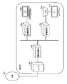
- FIG. 3 is a diagram showing one configuration of the communication network.
- the communication network includes an IP (Internet Protocol) network 301, a router 302, a communication device (R) 303, a communication device (S) 304, a communication device (T) 306, a PC 305, and a set top.
- a box (Set Top Box: also expressed as “STB”) 307 and a TV 308 are included.
- the router 302 may be referred to as HGW.
- the STB 307 and the TV 308 are connected by a dedicated cable.
- FIG. 3 shows a typical configuration example of a communication network in a home.
- the PC 305 and the STB 307 are connected to the IP network 301 via the router 302 in another room.
- the IP network 301 is, for example, the Internet. Communication between rooms is connected using a transmission medium other than Ethernet (registered trademark).
- the “transmission medium” specifically refers to a power line, a coaxial line, a wireless LAN, a telephone line, and the like.
- the communication device (R) 303, the communication device (S) 304, and the communication device (T) 306 are used to bridge Ethernet (registered trademark).
- the communication device (R) 303 communicated with the communication device (S) 304 or the communication device (T) 306 on a transmission medium other than the Ethernet (registered trademark), but the communication device (S) 304 or the communication device ( T) 306 has transitioned to the “pause state”, so communication is not performed.
- the communication device (R) 303 detects that the non-communication state continues for a certain time or more, and transitions to the “pause state”.
- the communication device (R) 303 is activated every predetermined time after transitioning to the “pause state”, and repeats the operation of checking the communication state.
- Patent Document 3 discloses a power control method for a relay apparatus including a first interface (for example, IEEE 1394) and a second interface (for example, a wireless LAN). This method is to monitor the contents of the packet, select either the first interface or the second interface, and cut off the power supply to the unselected interface.
- a first interface for example, IEEE 1394
- a second interface for example, a wireless LAN
- the power supply of the second interface is cut off. If the first interface receives a packet in this state, the second interface returns to the normal operation state. Conversely, when the second interface is selected, the power supply of the first interface is cut off. In this state, if the second interface receives a packet, the first interface returns to the normal operation state.
- Patent Document 4 describes a case where a wireless LAN station is in a standby mode when a wireless LAN access point, a wireless LAN station, and a terminal device are connected via a wireless LAN network. Discloses a technique in which the access point discards packets other than the activation packet and shortens the packet reception processing time in the wireless LAN station to save power.
- the communication device does not transition to the “sleep state” indefinitely. This is because routers and HGWs are generally always powered on, and the connection state is always linked up. Particularly in homes, in order to connect to the Internet, in most cases, one communication device is connected to a router or HGW. In such a usage mode, at least one communication device does not transition to the “sleep state”.
- the connection state of Ethernet is also linked up. That is, in FIG. 3, the communication device (R) 303 surely turns off the power of the Ethernet (registered trademark) I / F (Interface) unit when the communication device (R) 303 transitions to the “dormant state”.
- the Ethernet connection state between 303 and the router 302 may be linked down.
- activation at regular intervals means that the power supply of the Ethernet (registered trademark) I / F unit is turned on during that period, and the Ethernet (registered trademark) connection state is linked up.
- Some recent routers have a power saving function.
- the power saving of the router is realized by stopping the electrical output to the unused port. If the PC or network device connected to the router is powered off, or if the cable is not properly inserted into the power outlet, the port is linked down.
- the router realizes power saving by stopping the electrical output to the port that is linked down. When the power of a PC or network device connected to the router is turned on, the port is linked up, and the router resumes electrical output to the port and performs normal communication.
- the Ethernet (registered trademark) port of the network device remains linked up.
- the packet can be received even when the power is off (or on standby).
- a specific packet such as a magic packet (registered trademark) (hereinafter referred to as an activation packet)
- the network device is allowed to wake up.
- the communication apparatus cannot use the method of detecting link down and transitioning to the “sleep state”.
- the communication device when the communication device detects that the packet is not transmitted from the network device for a certain time or longer, the communication device estimates that the network device is in a power-off (or standby) state, , It is possible to transition to the “sleep state”.
- the communication device (S) 304 detects that no packet is transmitted from the PC 305 for a predetermined time or longer, the communication device (S) 304 estimates that the PC 305 is in a power-off (or standby) state, and transitions to a “sleep state”. If there is at least one communication device (in this case, the communication device (S)) that has transitioned to the “dormant state” while the port is linked up, the communication device (R) 303 will connect the Ethernet (registered trademark) I / O. Do not stop part F. The Ethernet (registered trademark) connection state with the router 302 is maintained in the link-up state to prepare for reception of a packet from the router 302. If the received packet is an activation packet, it is necessary to wake up the communication device (S) 304.
- the Ethernet registered trademark
- the communication device (R) 303 when network devices compatible with WakeOnLAN are mixed, the communication device (R) 303 is required to operate differently from the operation described above. That is, when the network device does not support WakeOnLAN, the communication device (R) 303 should turn off the power of the Ethernet (registered trademark) I / F unit. However, when network devices compatible with WakeOnLAN coexist, the communication device (R) 303 should keep the power of the Ethernet (registered trademark) I / F unit on.
- the technique disclosed in Japanese Patent Application Laid-Open No. 2004-7187 is to cut off the power supply of the interface that is not selected from the first interface or the second interface.
- the means of monitoring the packet contents and selecting an interface cannot be applied.
- the case where network devices compatible with WakeOnLAN coexist is not considered.
- a communication device that relays communication of a first network using a second network.
- the communication device includes a first communication interface between the first network and the communication device, a second communication interface between the second network and the communication device, and part of the operation inside the communication device.
- a state transition control unit for controlling stop and restart. When the operation state of the communication device is the normal operation state, when the state transition control unit detects that there is no connection with the device on the first network, the operation of the second communication interface is stopped.
- the operation state of the communication device is configured to transition to the first dormant state and all other communication devices connected to the second network are detected to be in the first dormant state, By stopping the operation of one communication interface, the operation state of the communication device is changed to the second dormant state.
- the communication device is configured to transmit a message indicating the transition to the first dormant state on the second network immediately before the transition to the first dormant state.
- the communication device further includes a connection state detection unit for detecting a connection state with a device on the first network.
- a connection state detection unit for detecting a connection state with a device on the first network.
- the connection state detection unit detects that there is a connection between the communication device and a device on the first network
- the state transition control unit puts the communication device in a normal operation state. It is comprised so that it may make a transition.
- the communication device further includes a packet detection unit for detecting a packet on the second network.
- the state transition control unit is configured to cause the communication device to transition to the normal operation state.
- the state transition control unit detects that a packet has not been received from a device connected to the first network for a predetermined time, the first communication While maintaining the operation state of the interface and the operation state of the second communication interface, a part of the internal circuit other than the state transition control unit in the communication device is stopped, thereby causing the communication device to transition to the third sleep state. It is configured as follows.
- the state transition control unit detects that a BYE packet has been received from a device connected to the first network
- the state change control unit and the operation state of the first communication interface The communication device is configured to transition to the third dormant state by stopping a part of the internal circuits other than the state transition control unit in the communication device while maintaining the operation state of the communication interface of 2.
- the communication device is configured to transmit a message indicating the transition to the third sleep state to the second network immediately before the transition to the third sleep state.
- the communication device further includes a packet detection unit for detecting a packet on the second network.
- the state transition control unit is configured to change the state of the communication device to the normal operation state. .
- the communication apparatus further includes a packet monitoring unit for monitoring a packet transmitted from a device on the first network.
- a packet monitoring unit for monitoring a packet transmitted from a device on the first network.
- the state transition control unit is configured to shift the communication device to a normal operation state Has been.
- the state transition control unit is configured such that at least one of the other communication devices connected to the second network is in the third dormant state, When it is detected that all the remaining communication devices are in the first dormant state, the operation state of the first communication interface and the operation state of the second communication interface are maintained and the state other than the state transition control unit in the communication device.
- the communication device is configured to transition to the fourth hibernation state by stopping a part of the internal circuit.
- the communication device further includes a packet detection unit for detecting a packet on the second network.
- the state transition control unit is configured to change the state of the communication device to the normal operation state. .
- the communication apparatus further includes a packet monitoring unit for monitoring a packet transmitted from a device on the first network.
- a packet monitoring unit for monitoring a packet transmitted from a device on the first network.
- the state transition control unit causes the communication device to transition to the normal operation state. It is configured.
- a communication system in which any of the communication devices described above is connected to a second network.
- a method for transitioning the state of a communication device that relays communication of a first network using a second network.
- the communication device includes a first communication interface between the first network and the communication device, and a second communication interface between the second network and the communication device.
- the communication device detects that there is no connection with a device on the first network when the operation state of the communication device is a normal operation state, the communication device stops the operation of the second communication interface.
- the operation state of the first communication interface is detected and the operation of the first communication interface is detected when it is detected that all the other communication devices connected to the second network are in the first dormant state. And stopping the operation state of the communication device to the second dormant state.
- the method further includes the step of transitioning the communication device to the third sleep state by stopping a part of the internal circuit of the communication device while maintaining the operation state and the operation state of the second communication interface.
- the method detects the operation state of the first communication interface and the second state.
- the method further includes the step of transitioning the communication device to the third dormant state by stopping a part of the internal circuit of the communication device while maintaining the operation state of the communication interface.
- the method when the communication device is in a normal operation state, at least one communication device among the other communication devices connected to the second network is in the third dormant state, and the other remaining devices.
- the method further includes the step of transitioning the communication device to the fourth dormant state.
- the power consumption of the entire network can be reduced.
- the internal circuit of the communication device can be appropriately stopped, and the network device can be started by a start packet. .
- FIG. 3 is a diagram showing details of an analog front end unit 105.
- FIG. It is a figure showing one structure of a communication network. It is a figure showing the structure of the preamble transmitted according to HomePlugAV specification. This is a summary of which blocks are to be stopped for the resting state (A) and the resting state (B) of the power line communication apparatus 101.
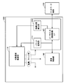
- FIG. 1 is a diagram illustrating an outline of a configuration of a communication apparatus according to the first embodiment.
- the power line communication device 101 is described as a communication device in mind, but the communication mode is not limited to power line communication.
- the communication apparatus should just be an apparatus which has a communication function at least. For example, it can be included in a router, HGW, relay device, hub, Y cable, PC, NAS, printer, HDD recorder, TV, and the like.
- the power line communication device 101 includes a power supply unit 102, a power supply circuit 103, an oscillator 104, an analog front end unit 105, a communication control unit 106, an Ethernet (registered trademark) I / F 107, a connection state detection unit 108, A packet detection unit 109 and a state transition control unit 110 are provided.
- the power supply unit 102 includes an AC (Alternating Current) -DC (Direct Current) converter (not shown), a coupling transformer (not shown), and the like.
- the AC-DC converter supplies power to the power supply circuit 103 and other components.
- the coupling transformer superimposes and separates the power supply / PLC carrier signal with respect to a power supply line called a power line.
- the power supply circuit 103 converts the power supply voltage (+11 V) supplied from the power supply unit 102 into a power supply voltage (+3.3 V or the like) required for each part of the power line communication device 101.
- the power supply circuit 103 includes a DC-DC converter, a switching regulator, and the like.
- the power supply voltage before conversion or the power supply voltage after conversion is supplied to each unit such as the state transition control unit 110.
- the oscillator 104 generates a clock (such as 75 MHz) necessary for each unit of the power line communication apparatus 101.
- the oscillator 104 is realized as a combination of a crystal oscillator or a crystal oscillator and a PLL (Phase Locked Loop).
- the generated clock is supplied to each unit such as the state transition control unit 110.
- the analog front end unit 105 includes an A / D (Analog to Digital) converter, a D / A (Digital to Analog) converter, a transmission / reception filter circuit, and the like.
- the analog front end unit 105 is divided into a transmission system and a reception system. Details will be described with reference to FIG.
- the communication control unit 106 includes a digital modulation / demodulation unit, a medium access control unit, an Ethernet (registered trademark) I / F control unit, and the like.
- the digital modulation / demodulation unit is in charge of the PHY (Physical) layer. Specifically, packet detection, symbol timing synchronization, FFT / IFFT (Fast Fourier Transform / Inverse FFT), encoding / decoding for error correction, and the like are performed. These are processes generally required for an OFDM (Orthogonal Frequency Division Multiplex) transmission / reception apparatus.
- OFDM Orthogonal Frequency Division Multiplex
- the media access control unit is in charge of the MAC (Media Access Control) layer. Specifically, it performs access control such as CSMA / CA (Carrier Sense Multiple Access with Collision Avoidance) and network management. Specifically, the communication control unit 106 is realized as an IC chip for power line communication.
- MAC Media Access Control
- CA Carrier Sense Multiple Access with Collision Avoidance
- the communication control unit 106 is realized as an IC chip for power line communication.
- the communication control unit 106 includes a CPU (Central Processing Unit) and other processors, a DRAM (Dynamic Random Access Memory), a flash ROM (Read Only Memory), and the like. Including storage devices.
- CPU Central Processing Unit
- DRAM Dynamic Random Access Memory
- flash ROM Read Only Memory
- the Ethernet (registered trademark) I / F control unit is electrically connected to the Ethernet (registered trademark) I / F 107 and transmits / receives data to / from the network device 150.
- the communication control unit 106 When the power line communication device 101 is in a normal operation state, the communication control unit 106 notifies the state transition control unit 110 to that effect when detecting that the no-communication state has continued for a predetermined time or more. Or the communication control part 106 will notify the state transition control part 110 that it will detect that all the other communication apparatuses which comprise a power line communication network changed to the "rest state.”
- the Ethernet (registered trademark) I / F 107 interfaces with an external network device 150.
- the Ethernet (registered trademark) I / F 107 is specifically an Ethernet (registered trademark) PHY or an Ethernet (registered trademark) switch device.
- the connection state detection unit 108 detects the connection state with the network device 108. This detection does not require special hardware.
- the link detection function of the Ethernet (registered trademark) PHY or the Ethernet (registered trademark) switch device constituting the Ethernet (registered trademark) I / F 107 is used.
- the connection state can be detected by reading a register in the Ethernet (registered trademark) PHY or reading an output signal from the Ethernet (registered trademark) PHY. The same applies to an Ethernet (registered trademark) switch device.
- connection state detection unit 108 When the connection state detection unit 108 detects the connection state with the network device 150, the connection state detection unit 108 notifies the state transition control unit 110 to that effect.
- connection state with the network device 150 is detected by the Ethernet (registered trademark) I / F 107 and the connection state detection unit 108. Therefore, even if blocks that do not affect detection (for example, the communication control unit 106, the analog front end unit 105, etc.) are stopped, the connection detection function is maintained.
- the packet detection unit 109 receives the input of data obtained by analog / digital conversion of the PLC communication data signal by the analog front end unit 105, and determines whether or not a valid PLC communication signal is received. Judgment based on. When detecting that a valid PLC communication signal is received, the packet detection unit 109 notifies the state transition control unit 110 of the fact. Details of the processing will be described with reference to FIG.
- the state transition control unit 110 controls the power supply, clock, and other control signals of each unit based on the inputs from the communication control unit 106, the connection state detection unit 108, and the packet detection unit 109. Specifically, the state transition control unit 110 is realized by executing a program configured to realize the processing by a CPU or other processor.
- the state transition control unit 110 may be a CPU separate from the processor that implements the communication control unit 106, or may be realized by a CPU included in the communication control unit 106.
- the state transition control unit 110 when the state transition control unit 110 is realized by a CPU included in the communication control unit 106, the CPU is configured to be activated by an external interrupt signal when the communication control unit 106 is stopped. Will be. In this case, for example, the CPU in the communication control unit 106 is switched from the standby state to the active state by an interrupt signal from the packet detection unit 109 or the connection state detection unit 108.
- FIG. 2 is a diagram showing details of the analog front end unit 105.
- the analog front end unit 105 includes a reception system 210 and a transmission system 220.
- the reception system 210 includes a reception filter 1051, an AGC (Automatic Gain Control) 1052, and an A / D converter 1053.
- the transmission system 220 includes a D / A converter 1054, a transmission filter 1055, and a line driver 1056.
- the reception filter 1051 passes only signals in a band necessary for PLC communication.
- the AGC 1052 automatically adjusts the signal gain.
- the A / D converter 1053 converts an analog signal into digital data, and outputs the digital data generated by the conversion.
- Digital data is input to the packet detection unit 109 and the communication control unit 106.
- the communication control unit 106 executes processing necessary for PLC communication, such as packet detection, symbol timing synchronization, and FFT.
- the packet detection unit 109 performs only packet detection. Specifically, the packet detection unit 109 is an autocorrelator.
- the packet detection unit 109 may be an independent external circuit that is separate from the communication control unit 106, or may be included in the communication control unit 106. Even when the packet detection unit 109 is included in the communication control unit 106, it is desirable that power supply and clock supply to the packet detection unit 109 and power supply and clock supply to the other are independent. .
- the circuit configuration of the packet detection unit 109 is slightly smaller than the circuit configuration of the communication control unit 106 as a whole. Also, software processing is not necessary.
- the correlation coefficient corr is in the range from ⁇ 1 to +1, and the closer to +1, the more positive the correlation. If the value of corr satisfies equation (4), the correlator determines that there is a correlation.
- corr_threshold is a threshold value of the correlation value, and is set to 0.75, for example.
- Formula (1) may be substituted by Formula (5).
- the correlation coefficient corr is called an autocorrelation coefficient.
- the correlation coefficient corr is called a cross-correlation coefficient.
- the packet detection unit 109 can detect a packet using the autocorrelation coefficient. Specifically, the packet detection unit 109 calculates a correlation coefficient with its own signal N points before.
- the structure of the preamble transmitted according to the HomePlugAV standard will be described.
- a preamble as shown in FIG. 4 is transmitted prior to packet transmission. Since the preamble pattern repeats with a period of 5.12 microseconds ( ⁇ s), sampling at 75 MHz should receive a similar signal sequence for every 384 points.
- the packet detection based on the above description can be realized with, for example, three multipliers and a few circuits. This is a slightly smaller circuit compared to an FFT that requires at least 256 multipliers.
- the blocks necessary for detecting the packet on the PLC are only the reception system 210 and the packet detection unit 109 of the analog front end unit 105, which are slightly smaller than the entire circuit. Blocks that do not affect the operation (the transmission system 220 of the analog front end unit 105, the communication control unit 106, the Ethernet (registered trademark) I / F 107, etc.) may be stopped.
- the packet detection unit 109 can detect a wireless packet signal during this period.
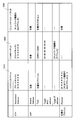
- FIG. 5 summarizes which blocks are stopped in the resting state (A) and the resting state (B).
- the hibernation state (A) refers to an “hibernation state” that transitions due to Ethernet (registered trademark) link down.
- the hibernation state (B) refers to a “hibernation state” that transitions by detecting that all other communication devices on the PLC are in the hibernation state. However, it does not support WakeOnLAN.
- Block (X) includes the reception system 210 and the packet detection unit 109 of the analog front end unit 105.
- the block (Y) includes the communication control unit 106 and the transmission system 220 of the analog front end unit 105.
- the block (Z) includes an Ethernet (registered trademark) I / F 107 and a connection state detection unit 108.
- a block written as “stopped” does not necessarily need to be stopped, and a part or all of the blocks may be operated. You may select flexibly according to the mounting of the power line communication apparatus 101. Further, in FIG. 5, a block written as “operating” does not necessarily need to be operated at all times, and may be raised and operated intermittently. When operated intermittently, further reduction in power consumption can be realized.
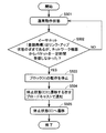
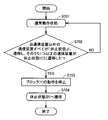
- FIG. 6 is a flowchart showing a procedure for transitioning to the sleep state (A).
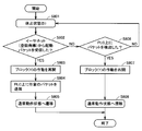
- FIG. 7 is a flowchart showing a procedure for returning from the sleep state (A) to the normal operation state.
- step S101 when power line communication apparatus 101 is in a normal state (step S101), when communication control unit 106 detects a link down of Ethernet (registered trademark) communication (step S102), block (X) And the operation of the block (Y) are stopped (step S103).
- Ethernet registered trademark
- the stop of the operation of each block is realized, for example, by stopping the power supply or the clock supply.
- the stop of the power supply is to switch the power supply converted by the power supply circuit 103 between ON and OFF using an FET (Field Effect Transistor).
- FET Field Effect Transistor
- the output of the switching regulator itself may be stopped.
- Stopping the clock supply is specifically masking the clock using an AND gate or the like.
- other methods such as controlling a power-down signal input to an IC (Integrated Circuit) chip, continuing to apply a reset signal, and masking an input data signal. Either method may be used. These controls are realized by executing software configured to realize the processing.
- the power line communication apparatus 101 notifies the other communication apparatuses connected to the network by broadcasting a packet indicating that the transition from the normal operation state to the dormant state (A) (step) S104).
- the notification in step S104 is useful for other communication apparatuses from the viewpoint of network management, but in the present embodiment, the processing in step S104 is not necessarily required.
- the power line communication apparatus 101 makes a transition to the dormant state (A) (step S105).
- the transition to the dormant state (A) is performed after elapse of a predetermined time from the process of step S103, for example.
- step S201 when the state of power line communication apparatus 101 is in the dormant state (A) (step S201), communication control unit 106 detects link up of Ethernet (registered trademark) (step S202). The operation of block (X) and the operation of block (Y) are resumed (step S203).
- the communication control unit 106 transmits an arbitrary packet on the PLC (step S204).
- the transmitted packet may not be special.
- a packet is transmitted as one of the procedures for configuring the network.
- the packet transmitted in step S204 has the role of waking up any communication device that has transitioned to the sleep state (B) described above.
- the packet transmitted in step S204 may be an alarm packet.
- the “wake-up packet” is for waking up a communication device that is resting on the PLC.
- the communication device switches its operation state from the sleep state to the normal standby state.
- the communication device that has recovered from the dormant state (A) confirms that there is no other communication device on the transmission medium, it continuously transmits “wake-up packets” for an appropriate time.
- step S205 the power line communication apparatus 101 transitions to a normal operation state (step S205).
- FIG. 8 is a flowchart showing a procedure for the power line communication apparatus 101 to transition to the dormant state (B).
- FIG. 9 is a flowchart showing a procedure for returning power line communication apparatus 101 to a normal operation state.
- step S301 when power line communication apparatus 101 is in a normal operation state (step S301), state control unit 110 determines that all communication apparatuses other than power line communication apparatus 101 itself have transitioned to a dormant state (A). When it is detected (step S302), the operation of the block (Y) and the operation of the block (Z) are stopped (step S303).
- step S302 the state transition control unit 110 executes the following process.
- the other communication apparatus broadcasts a packet indicating that before the other communication apparatus transitions to the dormant state (A)
- the power line communication apparatus 101 receives the packet to perform another communication. It is detected that the apparatus is in a dormant state (A).
- the power line communication apparatus 101 detects that no communication state continues for a certain time or longer on the PLC. In particular, in the case of PLC or wireless communication, it may be impossible to communicate at all due to changes in channel conditions. In preparation for such a case, it is meaningful for the power line communication apparatus 101 to detect that the no-communication state has continued for a certain period of time. Thereafter, the power line communication device 101 makes a transition to the dormant state (B) (step S304). When the power line communication apparatus 101 transitions to the dormant state (B), the Ethernet (registered trademark) I / F 107 is stopped, and as a result, the Ethernet (registered trademark) connection state is linked down.
- step S401 when the operation state of power line communication apparatus 101 is in the dormant state (B) (step S401), when packet detection unit 109 detects a packet on PLC (step S402), block (Y) And the operation of the block (Z) are resumed (step S403).
- step S404 the power line communication device 101 transitions to a normal operation state.
- the operation of power line communication apparatus 101 according to the present embodiment based on the structure and flowchart as described above will be described with reference to FIG.
- the power line communication apparatus 101 will be described as corresponding to the communication apparatus (R) 303, the communication apparatus (S) 304, and the communication apparatus (T) 306.
- the Ethernet (registered trademark) connection state between the communication device (S) 304 and the PC 305 is linked down.
- the communication device (S) 304 determines that the connection state with the network device is disconnected, and the operation state transitions to the dormant state (A).
- the communication device (S) 304 may notify the other communication device (R) 303 and the communication device (T) 306 by broadcast of a packet indicating the transition to the dormant state (A).
- the operation state of the communication device (T) 306 transitions to a dormant state (A).
- the communication device (R) 303 detects that the communication device (S) 304 or the communication device (T) 306 has transitioned to a dormant state (A). Alternatively, the communication device (R) 303 detects that the no-communication state continues for a certain time or longer on the PLC. Thereafter, the communication device (R) 303 transitions to a dormant state (B).
- the router 302 can also shift from the normal operation mode to the power saving mode.
- the Ethernet (registered trademark) connection state between the communication device (S) 304 and the PC 305 is link-up.
- the communication device (S) 304 determines that there is a connection state with the network device, and transitions to a normal operation state. At this time, the communication device (S) 304 transmits a packet as one of the procedures for configuring the network.
- the communication device (R) 303 When the communication device (R) 303 detects a packet on the PLC, the communication device (R) 303 transitions to a normal operation state.
- the Ethernet (registered trademark) connection state between the communication device (R) 303 and the router 302 is link-up.
- the router 302 returns from the power saving mode to the normal operation mode by detecting the link up. Note that the communication device (T) 306 remains in the dormant state (A) as long as the STB 307 is powered off.
- FIG. 10 is a diagram showing an outline of the configuration of the power line communication apparatus 1000 according to the second embodiment.
- the same number is attached
- the power line communication apparatus 1000 further includes a packet monitoring unit 111 in addition to the configuration of the power line communication apparatus 101 shown in FIG.
- the packet monitoring unit 111 is arranged between the Ethernet (registered trademark) I / F 107 and the communication control unit 106 and is configured to monitor a packet sent from the network device 150. Note that the power line communication apparatus 1000 according to the present embodiment need not monitor packets transmitted to the network device 150. Further, no packet is transmitted from the packet monitoring unit 111.
- Ethernet registered trademark
- F 107 the Ethernet (registered trademark) I / F 107 and the communication control unit 106 are connected by an MII (Media Independent Interface) bus, and packets can be monitored by this bus connection.
- MII Media Independent Interface
- the packet monitoring unit 111 determines whether or not a packet is flowing between the communication control unit 106 and the Ethernet (registered trademark) interface 107, or determines whether or not the packet is an activation packet.
- the packet monitoring unit 111 merely determines whether or not a packet is flowing, the Ethernet (registered trademark) PHY or Ethernet (registered trademark), which is the Ethernet (registered trademark) I / F 107, as in the connection state detection unit 108.
- the active detection function of a trademark switch device can be used. No special circuit is required. In this case, the CPU in the communication control unit 106 can be woken up from the packet monitoring unit 111 through an external interrupt signal.
- the packet monitoring unit 111 needs to be configured as an external circuit separate from the communication control unit 106 or as software operating on the CPU in order to determine whether the packet is an activation packet.
- the packet monitoring unit 111 may be an independent CPU that is separate from the communication control unit 106, or may be a CPU included in the communication control unit 106 in another aspect. However, if the packet monitoring unit 111 is realized on a CPU included in the communication control unit 106, the CPU of the communication control unit 106 must not be stopped.
- FIG. 11 is a diagram showing the definition of which block is to be stopped when the operation state of the power line communication apparatus 1000 is the dormant state (C) and the dormant state (D).
- the “pause state (C)” is an “pause state” in which Ethernet (registered trademark) remains in a link-up state, but transits when a packet is not received from the network device 150 for a certain period of time. That means. For example, it is assumed that the network device corresponding to WakeOnLAN is off (or in standby).
- the hibernation state (D) refers to a “hibernation state” in which a transition is made by detecting that all other communication devices on the PLC are in the hibernation state. However, unlike the dormant state (B), a case where WakeOnLAN compatible network devices are mixed is considered.
- the block (Z ′) includes an Ethernet (registered trademark) I / F 107, a connection state detection unit 108, a packet monitoring unit 111, and the like.
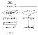
- FIG. 12 is a flowchart showing a procedure in which power line communication apparatus 1000 according to the second embodiment transitions from a normal operation state to a dormant state (C).
- FIG. 13 is a flowchart illustrating a procedure for power line communication apparatus 1000 to return from the sleep state (C) to the normal operation state.
- the Ethernet (registered trademark) remains in the link-up state.
- the communication control unit 106 detects that the packet has not been received from the network device 150 for a certain time (step S502), the communication control unit 106 stops the operation of the block (Y) (step S503). Thereafter, the communication control unit 106 broadcasts a packet indicating that the operation state of the power line communication apparatus 1000 is transitioned to a dormant state (C) (step S504).
- a predetermined time has elapsed since the transmission of the packet, the operating state of the power line communication apparatus 1000 transitions to a dormant state (C) (step S505).
- step S502 when the communication control unit 106 detects that a certain type of packet (herein referred to as a BYE packet) has been received from the network device 150, the communication control unit 106 may transition to a dormant state (C). .
- a “BYE packet” is a packet that is transmitted when the network device 150 shifts to power off (or standby). Depending on the network device 150, such a “BYE packet” may be transmitted.
- there is a bybye message which is one of the SSDP (Simple Service Discovery Protocol) protocols of UPnP (Universal Plug and Play).
- SSDP Simple Service Discovery Protocol
- UPnP Universal Plug and Play
- step S601 when power line communication apparatus 1000 is in the dormant state (C) (step S601), if packet monitoring unit 111 detects reception of an arbitrary packet from Ethernet (YES in step S602). ), The state transition control unit 110 resumes the operation of the block (Y) (step S603).
- the communication control unit 106 transmits an arbitrary packet on the PLC (step S604).
- the packet transmitted here does not have to be special.
- the communication control unit 106 transmits a packet as one of procedures for configuring the network. Note that the packet transmitted in step S604 has a role of waking up the communication apparatus if there is a communication apparatus in the dormant state (B) or the dormant state (D). Thereafter, the power line communication apparatus 1000 transitions to a normal operation state (step S605).
- step S602 when packet monitoring unit 111 does not detect reception of a packet from Ethernet (NO in step S602), if packet detection unit 109 detects a packet on the PLC (YES in step S606), The state transition control unit 110 resumes the operation of the block (Y) (step S607). Thereafter, the power line communication device 1000 transitions to a normal operation state (step S608).
- the power line communication apparatus 1000 transmits a packet received from the PLC to an Ethernet (registered trademark) communication network (for example, the network device 150) as part of a normal operation state.
- an Ethernet (registered trademark) communication network for example, the network device 150
- the packet received from the PLC is an activation packet
- the packet activates the network device 150.
- FIG. 14 is a flowchart showing a procedure in which power line communication apparatus 1000 transitions to a dormant state (D).
- FIG. 15 is a flowchart showing a procedure for the power line communication device to transition to a normal operation state.
- step S701 when the operation state of power line communication apparatus 1000 is a normal operation state (step S701), state transition control unit 110 sets all communication apparatuses other than power line communication apparatus 1000 to the “dormant state”.
- step S702 when a transition is detected and one or more of the communication devices transitions to a dormant state (C) (step S702), the block (Y) is stopped (step S703).
- step S702 the process in step S702 is executed as follows.
- the detection that all communication devices other than the power line communication device 1000 have transitioned to the “dormant state” is performed as follows.
- the power line communication apparatus 1000 receives the packet, so that the other communication apparatus is in the “pause state”. Detect that it has transitioned to.
- the power line communication apparatus 1000 detects that the non-communication state on the PLC continues for a certain time or more, the power line communication apparatus 1000 detects that another communication apparatus is in the “pause state”.
- the power line communication apparatus 1000 performs the following process in order to detect that one or more communication apparatuses of the plurality of communication apparatuses have transitioned to the dormant state (C). That is, since the other communication apparatus broadcasts a packet indicating that before transitioning to the dormant state (C), the power line communication apparatus 1000 receives the packet, thereby the one or more communication apparatuses Is transitioning to the dormant state (C). Thereafter, the power line communication apparatus 1000 makes a transition to the dormant state (D) (step S704).
- step S801 when power line communication apparatus 1000 is in a dormant state (D) (step S801), packet monitoring unit 111 receives an activation packet from an Ethernet (registered trademark) communication network (for example, network device 150).
- Ethernet registered trademark
- step S802 the operation of the block (Y) is resumed (step S803).
- the communication control unit 106 transmits an arbitrary packet on the PLC (step S804).
- the packet transmitted by the communication control unit 106 is not special.
- the communication control unit 106 transmits a packet as one of procedures for configuring a network. Note that the packet transmitted in step S804 has a role of activating any communication device that has transitioned to a dormant state (B) or a dormant state (D).
- the power line communication apparatus 1000 transitions to a normal operation state (step S805). Thereafter, as part of normal operation, the power line communication apparatus 1000 transmits a packet received from the Ethernet (registered trademark) to the power line via the power supply unit 102, and PLC is performed.
- Ethernet registered trademark
- the “unnecessary packet” refers to a packet that is irrelevant because a network device (compatible with WakeOnLAN) in a power-off (or standby) state is activated.
- the communication control unit 106 transmits such an “useless packet” on the PLC, the communication device that has transitioned to the dormant state (C) will wake up. Since this is a useless process, in this embodiment, packets other than the activation packet are not transmitted.
- An example of “useless packet” is a control packet in which a destination address is transmitted by a broadcast address or a multicast address, for example.
- the router 302 may transmit the “useless packet”, or may be transmitted by another network device (not shown) connected to the router 302.
- step S806 when packet monitoring unit 111 does not receive the activation packet (NO in step S802), when packet detection unit 109 detects a packet on the PLC (step S806), the operation of block (Y) is resumed. (Step S807).
- the power line communication apparatus 1000 transitions to a normal operation state (step S808).
- the activation packet is a packet for waking up a network device compatible with WakeOnLAN. Accordingly, the activation packet includes a MAC address, an IP address, and other information for specifying a network device.
- FIG. 16 is a diagram showing a schematic configuration of a magic packet 1610, an ARP (Address Resolution Protocol) packet 1620, and a unicast packet 1630 as activation packets.
- ARP Address Resolution Protocol
- the destination address (Destination Address) of the magic packet 1610 is a broadcast address, the source address (Source Address) is arbitrary, and the type (Type) of the transmission protocol is arbitrary.
- the magic packet 1610 is a packet that includes “ff: ff: ff: ff: ff: ff: ff” as a payload and the MAC address of the network device is repeatedly included 16 times.
- the destination address (Destination Address) of the ARP packet 1620 is a broadcast address
- the transmission protocol is the ARP protocol
- the inquiry IP address (Target IP address) is the IP address of the network device 150.
- the destination address of the unicast packet 1630 is the MAC address of the network device.
- the present invention is not limited to this example, and (2) the ARP packet and (3) the unicast packet may be excluded from the target of the startup packet, and other types of packets may be added to the target of the startup packet.
- the packet monitoring unit 111 checks whether or not the packet sent from the Ethernet (registered trademark) I / F is a packet as shown in FIG. 16, and identifies the activation packet. Therefore, the packet monitoring unit 111 needs to know in advance the MAC address and IP address information of the target device (network device compatible with WakeOnLAN). Therefore, in step S504, when the communication device transmits a message notifying that the communication device transitions to the dormant state (C), the communication device may include information specifying the network device bridged by the communication device in the message. Good. If there are a plurality of bridged network devices, the packet preferably includes information for identifying all the network devices.
- remote bridge information may be used if network management is properly performed on the PLC.
- Remote bridge information is information about network devices connected beyond the bridging communication device.
- FIG. 17 is a diagram showing an example of the format of the “message for notifying transition to the sleep state” sent in step S104 or step S504.
- the message format a vendor-specific message format in the HomePlugAV standard is shown.
- ODA is the message destination address (Original Destination Address).
- OSA indicates an address (Original Source Address) of a device that transmits a message.
- MTYPE indicates EtherType.
- a number assigned to IEEE is set.
- MMV is the version of the message.
- a number defined in the HomePlugAV standard is set.
- MMTYPE is a message identification number.
- the message identification number “0xA100” is defined as “transition to the dormant state (A)”
- the message identification number “0xA104” is defined as “transition to the dormant state (C)”.
- OUI is a vendor identification number (Vendor's OUI (Organizationally Unique Identifier)).
- a number assigned to IEEE is set.
- BTEI is a temporary device identifier (Bridging TEI (Temporary Equipment Identifier)) of a device that transmits a message.
- NBDA is the number of bridged network devices (Number of Bridged Destinations).
- BDA is address information (Bridged Destination Address) of a network device that is bridged. The address information includes only the MAC address or both the MAC address and the IP address. There are as many BDAs as there are bridged network devices.
- the communication device transitions to the dormant state (A)
- the address information of the network device that is bridged may be omitted.
- the communication apparatus transitions to a dormant state (A) or a dormant state (C)
- the message as shown in FIG. 17 is transmitted by broadcast.
- the communication device transmits twice in order to allow other communication devices to receive more reliably.
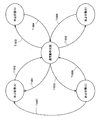
- FIG. 18 is a diagram illustrating the relationship between the normal operation state and each of the dormant states (A) to (D).
- Transition T1801 indicates that when the power line communication apparatus 1000 detects a link down of the Ethernet (registered trademark) (S102), the normal operation state transitions to the sleep state (A).
- Transition T1802 indicates that when the power line communication apparatus 1000 detects link up of the Ethernet (registered trademark) (S202), the state transitions from the hibernation state (A) to the normal operation state.
- Transition T1803 indicates that the power line communication apparatus 1000 changes from the normal operation state to the hibernation state (B) when all communication apparatuses other than the power line communication apparatus 1000 change to the hibernation state (A) (S302).
- Transition T1804 indicates that when the power line communication apparatus 1000 detects a packet on the PLC (S402), the state transitions from the sleep state (B) to the normal operation state.
- transition T1805 when the Ethernet (registered trademark) remains in the link-up state, but the power line communication apparatus 1000 has not received a packet from the network device for a certain period of time (S502), the normal operation state is changed to the sleep state (C). It shows that it changes to.
- Transition T1806 changes from the sleep state (C) to the normal operation state when the power line communication apparatus 1000 receives an arbitrary packet from the Ethernet (registered trademark) (S602) or detects a packet on the PLC (S606). Indicates a transition.
- a transition T1807 indicates that when the power line communication apparatus 1000 detects a link down of the Ethernet (registered trademark), the transition from the dormant state (C) to the dormant state (A) is performed.
- Transition T1808 is that when all the communication devices of the power line communication device 1000 have transitioned to the “sleep state” and one or more of the communication devices have transitioned to the sleep state (C) (S702), the power line communication device 1000 operates normally. A transition from a state to a dormant state (D) is shown. Transition T1808 is a normal operation from the dormant state (D) when the power line communication apparatus 1000 receives a startup packet from the Ethernet (registered trademark) (S802) or detects a packet on the PLC (S806). Indicates transition to a state.
- the communication device (S) 304 When the communication device (S) 304 detects that a packet has not been received from the PC 305 for a certain period of time (S502), the communication device (S) 304 transitions to a dormant state (C). The communication apparatus (S) 304 notifies the broadcast to the transition to the dormant state (C). When the power of the STB 307 is turned off, the communication device (T) 306 detects the turn-off, and transitions to the dormant state (A).
- the communication device (R) 303 detects that all communication devices other than itself have transitioned to a dormant state, and one or more of the communication devices (for example, the communication device (S) 304) transition to a dormant state (C). It is detected (S702). At this point, the communication device (R) 303 knows information that identifies the network device (for example, the PC 305) connected to the communication device (S) 304. This information is used to determine whether or not an activation packet has been received.
- the network device for example, the PC 305
- the communication device (R) 303 transitions to a dormant state (D).
- the Ethernet (registered trademark) connection state between the communication device (R) 303 and the router 302 is maintained in the link-up state.
- the operation of the power line communication apparatus 1000 is divided into Case 1 and Case 2.
- the communication device (S) 304 When the communication device (S) 304 detects a packet on the PLC, the communication device (S) 304 transitions to a normal operation state. After a while, when the preparation for the communication state on the power line is completed, the power line communication becomes possible. The communication device (R) 303 continues to hold the packet until power line communication is possible. When the communication device (R) 303 detects that power line communication is possible, the communication device (R) 303 transmits a packet to the PC 305. This packet is received by the communication device (S) 304. Upon receiving a packet (startup packet) from the communication device (R) 303, the communication device (S) 304 transmits the packet to the Ethernet (registered trademark).
- Ethernet registered trademark
- the PC 305 In response to receiving the activation packet, the PC 305 returns from a power-off (or standby) state to a normal operation state. On the other hand, the communication device (T) 306 remains in the dormant state (A) as long as the STB 307 is powered off.
- the PC 305 After a while, the PC 305 is turned on (by user operation). In response to turning on the power, the PC 305 transmits a packet for constructing a network (for example, a DHCP (Dynamic Host Configuration Protocol) packet).
- a packet for constructing a network for example, a DHCP (Dynamic Host Configuration Protocol) packet.
- the communication device (S) 304 transitions to a normal operation state. Thereafter, the communication device (S) 304 transmits the arbitrary packet on the PLC.
- the communication device (R) 303 When the communication device (R) 303 detects a packet on the PLC (S806), the communication device (R) 303 transitions to a normal operation state. After a while, the communication state on the power line becomes ready. The communication device (S) 304 continues to hold the packet until the communication state on the power line becomes ready.
- the communication device (R) 303 Upon receiving the packet from the communication device (S) 304, the communication device (R) 303 transmits the packet to the Ethernet (registered trademark) network.
- the communication device (T) 306 remains in the dormant state (A) as long as the STB 307 is powered off.
- the power line communication device 1000 can be appropriately shifted to the “pause state”.
- the transmission medium in each of the above-described embodiments described in detail is, for example, a power line.
- the transmission medium is not limited to the power line.
- a wireless LAN, a coaxial line, a telephone line, etc. may be used.
- the communication device and the network device are connected via Ethernet (registered trademark).
- Ethernet registered trademark
- IEEE 1394 Universal Serial Bus
- IEEE 1394 IEEE 1394
- the voltage level changes depending on the insertion / extraction of the cable, and therefore it is possible to electrically determine the presence / absence of the connection state.
- the “network” in the present embodiment has a property that it is possible to electrically determine the presence / absence of a connection state using a change in voltage level or the like, and the interface is stopped from the connected device side. As long as the connection can be disconnected, it is sufficient.
Landscapes
- Engineering & Computer Science (AREA)
- Computer Security & Cryptography (AREA)
- Computer Networks & Wireless Communication (AREA)
- Signal Processing (AREA)
- Small-Scale Networks (AREA)
- Cable Transmission Systems, Equalization Of Radio And Reduction Of Echo (AREA)
Abstract
通信ネットワークにおける省電力を実現する。電力線通信装置の状態遷移方法は、当該電力線通信装置が通常状態であるときに、通信制御部がイーサネット(登録商標)通信のリンク・ダウンを検出するステップと、ブロック(X)の動作とブロック(Y)の動作とを停止させるステップと、電力線通信装置が通常の動作状態から休止状態(A)に遷移する旨を表わすパケットをブロードキャストすることにより、ネットワークに接続されている他の情報通信装置に通知するステップと、その後、電力線通信装置が休止状態(A)へ遷移するステップとを含む。
Description
本発明は、無線LAN通信や電力線通信、同軸線通信、電話線通信などを備えた通信装置に関し、通信装置の状態遷移方法、通信システムに関する。
家庭内の通信ネットワークとして、イーサネット(登録商標)(Ethernet(登録商標))をはじめとして、IEEE(Institute of Electrical and Electronics Engineers)802.11b/g/a/nなどの無線LAN(Local Area Network)通信、HomePlugAVなどの電力線通信(PLC:Power Line Communication)、同軸線通信、電話線通信などが普及している。
一部の無線LAN通信装置や電力線通信装置などでは、イーサネット(登録商標)のデータ信号をイーサネット(登録商標)以外の伝送媒体を使って離れた場所へ伝送し、再びイーサネット(登録商標)のデータ信号に戻すという動作が行われている。このような動作をする装置はブリッジと呼ばれている。ブリッジは、PC(Personal Computer)などのネットワーク機器に容易に導入できる利点がある。ドライバなどの特別なソフトウェアを必要としないからである。ただし、いつでも利用できるようにするには、ブリッジの電源を常時オンにしておく必要がある。以下、本明細書では、「通信装置」をブリッジ、または、ブリッジを含む装置という意味で使用する。たとえば、ルータ、HGW(Home Gate Way)、中継装置、ハブ、PC(パーソナルコンピュータ)、NAS(Network-Attached Storage)、プリンタ、HDD(Hard Disk Drive)レコーダ、TV等に含まれ得る。また、本明細書では、「通信装置」に接続される機器をネットワーク機器と総称して表記する。
近年、環境問題への意識の高まりとともに省電力化を求める声が日増しに高まっている。常時電源オンにしておかなければならない通信装置は、使用していない場合であっても電力を消費してしまうため、消費者から敬遠される傾向がある。
そこで、使用していない場合に、通信装置を「休止状態」に遷移させる技術がある。「休止状態」とは、内部回路の一部の電源供給を停止する、あるいは、クロック供給を停止することで実現される状態である。また、「休止状態」は、制御信号を制御すること等で実現される場合もある。「休止状態」は、他にも「省電力モード」、「スタンバイ・モード」、「パワー・セーブ・モード」、「スリープ・モード」、「待機モード」などと呼ばれることがある。本明細書では、「休止状態」を上記のように定義する。
欧州特許出願公開第1667339号公報(特許文献1)、あるいは、特開2007-336174号公報(特許文献2)は、通信装置を使用していない場合に、「休止状態」に遷移させることによって消費電力を下げる技術を開示している。
欧州特許出願公開第1667339号公報によると、通信装置が使用されているかどうかは、通信装置に接続されているネットワーク機器との接続状態を検出することで判定できる。通信装置は、ネットワーク機器との接続が切断されていることを検出すると、使用されていないと判断し、「休止状態」に遷移する。
ネットワーク機器との接続状態を検出する手段としては、以下のものがある。たとえば、通信装置とネットワーク機器がイーサネット(登録商標)で接続されているならば、通信装置に内蔵されているイーサネット(登録商標)PHY(物理層)のリンク検出機能を利用できる。リンク検出機能は、イーサネット(登録商標)PHY内のレジスタ読み出し、または、イーサネット(登録商標)PHYからの出力信号を読み出すことで検出できる。イーサネット(登録商標)ケーブルが接続されており、かつ、イーサネット(登録商標)接続先のネットワーク機器が電源オンである場合はリンク・アップとなる。イーサネット(登録商標)ケーブルが接続されていない、または、イーサネット(登録商標)ケーブルが接続されていてもイーサネット(登録商標)接続先のネットワーク機器が電源オフである場合はリンク・ダウンとなる。
また、特開2007-336174号公報は、さらに、電力線通信ネットワーク上の無通信状態を検出して「休止状態」に遷移させるという技術を開示している。電力線通信端末は、電力線通信ネットワーク上の無通信状態を一定時間以上続いていることを検出すると、「休止状態」に遷移させる。その後、固定または可変の一定時間毎に起動し、電力線通信ネットワーク上の通信状態を確認し、通信がなければ再び「休止状態」に遷移させる。
図3は、通信ネットワークの一構成を表す図である。図3において、通信ネットワークは、IP(Internet Protocol)網301と、ルータ302と、通信装置(R)303と、通信装置(S)304と、通信装置(T)306と、PC305と、セットトップボックス(Set Top Box:「STB」とも表わす)307と、TV308とを含む。ルータ302は、HGWと呼ばれることもある。STB307とTV308とは、一例として、専用ケーブルで接続されている。図3は、家庭内における通信ネットワークの典型的の構成例を示している。
詳しくは、PC305およびSTB307は、別の部屋にあるルータ302を経由して、IP網301に接続されている。IP網301は、たとえば、インターネットである。部屋と部屋との間の通信は、イーサネット(登録商標)以外の伝送媒体を使って接続される。ここで、「伝送媒体」とは、具体的には、電力線、同軸線、無線LAN、電話線等をいう。通信装置(R)303、通信装置(S)304、通信装置(T)306は、イーサネット(登録商標)をブリッジするために使用される。
[特許文献1、特許文献2の実施の形態1に基づく動作の説明]
図3を参照して、通信装置を「休止状態」に遷移させる方法を説明する。PC305を電源オフにする。通信装置(S)304とPC305との間のイーサネット(登録商標)による通信がリンク・ダウンとなる。通信装置(S)304は、ネットワーク機器との接続状態が切断されていると判断し、「休止状態」に遷移する。同様に、STB307を電源オフにすると、通信装置(T)306は「休止状態」に遷移する。通信装置(R)303は、ルータ302が常時電源オンになっているという前提があるので、「休止状態」には遷移しない。
図3を参照して、通信装置を「休止状態」に遷移させる方法を説明する。PC305を電源オフにする。通信装置(S)304とPC305との間のイーサネット(登録商標)による通信がリンク・ダウンとなる。通信装置(S)304は、ネットワーク機器との接続状態が切断されていると判断し、「休止状態」に遷移する。同様に、STB307を電源オフにすると、通信装置(T)306は「休止状態」に遷移する。通信装置(R)303は、ルータ302が常時電源オンになっているという前提があるので、「休止状態」には遷移しない。
[特許文献2(実施の形態5)に基づく動作]
通信装置(R)303は、通信装置(S)304や通信装置(T)306とイーサネット(登録商標)以外の伝送媒体上で通信をしていたが、通信装置(S)304や通信装置(T)306が「休止状態」に遷移したため、通信が行われなくなる。通信装置(R)303は、無通信状態が一定時間以上続いていることを検出し、「休止状態」に遷移する。通信装置(R)303は、「休止状態」に遷移した後、一定時間毎に起動し、通信状態を確認するという動作を繰り返す。
通信装置(R)303は、通信装置(S)304や通信装置(T)306とイーサネット(登録商標)以外の伝送媒体上で通信をしていたが、通信装置(S)304や通信装置(T)306が「休止状態」に遷移したため、通信が行われなくなる。通信装置(R)303は、無通信状態が一定時間以上続いていることを検出し、「休止状態」に遷移する。通信装置(R)303は、「休止状態」に遷移した後、一定時間毎に起動し、通信状態を確認するという動作を繰り返す。
また、特開2004-7187号公報(特許文献3)は、第1のインタフェース(たとえばIEEE1394)と第2のインタフェース(たとえば無線LAN)を備える中継装置の電源制御方法を開示している。この方法は、パケットの内容を監視して、第1のインタフェースか第2のインタフェースかいずれかを選択し、選択されなかったインタフェースへの電源供給を遮断するというものである。
この方法によると、第1のインタフェースが選択されているときは、第2のインタフェースの電源供給が遮断される。この状態で、第1のインタフェースがパケットを受信すれば、第2のインタフェースは、通常動作状態に復帰する。逆に、第2のインタフェースが選択されているときは、第1のインタフェースの電源供給が遮断される。この状態で、第2のインタフェースがパケットを受信すれば、第1のインタフェースは、通常動作状態に復帰する。
さらに、特開2005-244329号公報(特許文献4)は、無線LANアクセスポイントと無線LANステーションと端末機器とが無線LANネットワークで接続されているときに、無線LANステーションが待機モードである場合には、アクセスポイントが起動パケット以外のパケットを破棄し、無線LANステーションでのパケット受信処理時間を短縮して省電力化を図るという技術を開示している。
ネットワーク機器との接続状態を検出して「休止状態」に遷移させる技術では、ネットワーク機器がルータやHGWなどである場合、通信装置はいつまでも「休止状態」に遷移しない。なぜなら、ルータやHGWは一般的に常時電源オンになっており、接続状態は常にリンク・アップされた状態となるからである。特に、家庭内ではインターネットに接続するために、片方の通信装置をルータやHGWに接続する場合がほとんどである。このような利用形態では少なくとも1つの通信装置は「休止状態」に遷移することがない。
また、特開2007-336174号公報に開示された技術によると、以下のような問題がある。それは、電力線通信装置が起動されると、イーサネット(登録商標)の接続状態もリンク・アップされてしまうことである。すなわち、図3において、通信装置(R)303は、「休止状態」に遷移しているときは確かにイーサネット(登録商標)I/F(Interface)部の電源をオフにして、通信装置(R)303とルータ302との間のイーサネット(登録商標)の接続状態は、リンク・ダウンになるかもしれない。しかし、一定時間毎に起動されるということは、その間はイーサネット(登録商標)I/F部の電源は、オンになり、イーサネット(登録商標)接続状態はリンク・アップとなる。
ところで、最近のルータには、省電力機能を備えたものがある。ルータの省電力は、未使用ポートへの電気出力を停止することで実現されている。ルータに接続されているPCやネットワーク機器が電源オフになっている場合、あるいは、ケーブルが正しく電源コンセントに挿入されていない場合、そのポートは、リンク・ダウンされた状態となる。ルータは、そのリンク・ダウンされているポートへの電気出力を停止することによって省電力を実現する。ルータに接続されているPCやネットワーク機器の電源をオンにすれば、ポートはリンク・アップされた状態になり、ルータはそのポートへの電気出力を再開させ、通常の通信を実行する。上記のような未使用ポートへの電気出力を制限することにより、50%近くもの省電力を実現しているルータもある。
図3において、通信装置(R)303とルータ302との間のイーサネット(登録商標)接続状態がリンク・アップされていると、ルータ302は接続しているポートを省電力に移行しない。その結果、ルータ302を含めてネットワーク全体の消費電力があまり下がらないことになる。ネットワーク全体の消費電力を考えると、通信装置(R)303は、「休止状態」に遷移しているときは、常に、イーサネット(登録商標)I/F部の電源をオフにしておくことが望ましい。イーサネット(登録商標)の接続状態をリンク・ダウンさせることで、ルータ302も省電力に移行できるからである。ルータ302も含めてネットワーク全体の消費電力を少なくすることが望ましい。
また、従来技術では、WakeOnLANに対応したネットワーク機器が混在した場合における「休止状態」への遷移方法が十分検討されていなかった。
WakeOnLANに対応したネットワーク機器では、ネットワーク機器が電源オフ(またはスタンバイ)の状態となっていても、そのネットワーク機器のイーサネット(登録商標)ポートは、リンク・アップされた状態を維持する。そして、電源オフ(またはスタンバイ)の状態でも、パケットが受信できるようになっている。そして、マジックパケット(登録商標)などの特定のパケット(以下、起動パケットと呼ぶ)を受信すると、そのネットワーク機器は起き上がれるようになっている。このようなネットワーク機器がある場合、通信装置は、リンク・ダウンを検出して「休止状態」に遷移するという手法は使えない。
このような場合でも、通信装置は、たとえば、ネットワーク機器から一定時間以上にわたってパケットが送信されないことを検出すると、ネットワーク機器が電源オフ(またはスタンバイ)の状態となっていると推定し、自装置を、「休止状態」に遷移することは可能である。
図3において、PC305がWakeOnLANに対応しており、PC305が電源オフ(またはスタンバイ)に移行したものとする。通信装置(S)304は、PC305から一定時間以上にわたってパケットが送信されないことを検出すると、PC305が電源オフ(またはスタンバイ)の状態となっていると推定し、「休止状態」に遷移する。ポートがリンク・アップされた状態のまま「休止状態」に遷移した通信装置(ここでは、通信装置(S))がひとつでもあると、通信装置(R)303は、イーサネット(登録商標)I/F部を停止してはならない。ルータ302との間のイーサネット(登録商標)接続状態をリンク・アップに維持し続けて、ルータ302からのパケットの受信に備える。そして、受信したパケットが起動パケットであるならば、通信装置(S)304を起こしにいく必要がある。
つまり、WakeOnLANに対応したネットワーク機器が混在した場合、通信装置(R)303には、先ほど述べた動作とは異なる動作が求められる。つまり、ネットワーク機器が、WakeOnLAN非対応の場合は、通信装置(R)303は、イーサネット(登録商標)I/F部の電源をオフにすべきである。しかし、WakeOnLANに対応したネットワーク機器が混在した場合、通信装置(R)303は、イーサネット(登録商標)I/F部の電源をオンに維持すべきである。
また、特開2004-7187号公報に開示されている技術は、第1のインタフェースか第2のインタフェースかいずれか選択されなかった方のインタフェースの電源供給を遮断するというものである。しかしながら、パケットの内容を監視して、インタフェースを選択するという手段が適用できない場合もある。また、WakeOnLANに対応したネットワーク機器が混在した場合のことは、考慮されていない。
特開2005-244329号公報に記載されている技術は、アクセスポイントが起動パケット以外のパケットを破棄するというものである。しかしながら、アクセスポイントがスリープすることまでは考慮されていない。
したがって、ネットワーク全体の消費電力を少なくすることができる通信装置が必要とされている。
また、WakeOnLANに対応したネットワーク機器が混在した場合でも、内部回路を適切に停止させることができ、また、起動パケットによってネットワーク機器を起動できる通信装置が必要とされている。
また、ネットワーク全体の消費電力を少なくすることができる通信装置の状態遷移方法が必要とされている。
また、他の局面において、WakeOnLANに対応したネットワーク機器が混在した場合でも、内部回路を適切に停止させることができ、また、起動パケットによってネットワーク機器を起動できる通信装置の状態を遷移させる方法が必要とされている。
さらに他の局面において、ネットワーク全体の消費電力を少なくすることができる通信システムが必要とされている。
一実施の形態に従うと、第1のネットワークの通信を第2のネットワークを用いて中継する通信装置が提供される。この通信装置は、第1のネットワークと通信装置との間の第1の通信インターフェイスと、第2のネットワークと通信装置との間の第2の通信インターフェイスと、通信装置の内部における動作の一部停止および再開を制御するための状態遷移制御部とを備える。通信装置の動作状態が通常動作状態であるときに、状態遷移制御部は、第1のネットワーク上の機器との接続がないことを検出すると、第2の通信インターフェイスの動作を停止させることにより、通信装置の動作状態を、第1の休止状態に遷移させるように構成されており、第2のネットワークに接続されている他の通信装置すべてが第1の休止状態にあることを検出すると、第1の通信インターフェイスの動作を停止させることにより、通信装置の動作状態を第2の休止状態に遷移させるように構成されている。
好ましくは、通信装置は、第1の休止状態に遷移する直前に、第1の休止状態に遷移する旨のメッセージを第2のネットワーク上に送信するように構成されている。
好ましくは、通信装置は、第1のネットワーク上の機器との接続状態を検出するための接続状態検出部をさらに備える。通信装置が第1の休止状態であるとき、接続状態検出部が、通信装置と第1のネットワーク上の機器との接続があることを検出すると、状態遷移制御部は、通信装置を通常動作状態に遷移させるように構成されている。
好ましくは、通信装置は、第2のネットワーク上のパケットを検出するためのパケット検出部をさらに備える。通信装置が第2の休止状態であるとき、パケット検出部が第2のネットワーク上のパケットを検出すると、状態遷移制御部は、通信装置を通常動作状態に遷移させるように構成されている。
好ましくは、通信装置が通常動作状態であるとき、状態遷移制御部は、第1のネットワークに接続されている機器からパケットを予め定められた時間受信しなかったことを検出すると、第1の通信インターフェイスの動作状態と第2の通信インターフェイスの動作状態とを維持したまま、通信装置における状態遷移制御部以外の内部回路の一部を停止させることにより、通信装置を第3の休止状態に遷移させるように構成されている。
好ましくは、通信装置が通常動作状態であるとき、状態遷移制御部は、第1のネットワークに接続されている機器からBYEパケットを受信したことを検出すると、第1の通信インターフェイスの動作状態と第2の通信インターフェイスの動作状態とを維持したまま、通信装置における状態遷移制御部以外の内部回路の一部を停止させることにより、通信装置を第3の休止状態に遷移させるように構成されている。
好ましくは、通信装置は、第3の休止状態に遷移する直前に、第3の休止状態に遷移する旨のメッセージを第2のネットワークに送信するように構成されている。
好ましくは、通信装置は、第2のネットワーク上のパケットを検出するためのパケット検出部をさらに備える。通信装置が第3の休止状態であるとき、パケット検出部が第2のネットワーク上のパケットを検出すると、状態遷移制御部は、通信装置の状態を通常動作状態に遷移させるように構成されている。
好ましくは、通信装置は、第1のネットワーク上の機器から送信されたパケットを監視するためのパケット監視部をさらに備える。通信装置が第3の休止状態であるとき、パケット監視部が第1のネットワーク上の機器からのパケットの受信を検出すると、状態遷移制御部は、通信装置を通常動作状態に遷移させるように構成されている。
好ましくは、通信装置が通常動作状態のとき、状態遷移制御部は、第2のネットワークに接続されている他の通信装置のうち少なくとも1以上の通信装置が第3の休止状態にあり、他の残りの通信装置すべてが第1の休止状態にあること、を検出すると、第1の通信インターフェイスの動作状態と第2の通信インターフェイスの動作状態とを維持したまま、通信装置における状態遷移制御部以外の内部回路の一部を停止させることにより、通信装置を第4の休止状態に遷移させるように構成されている。
好ましくは、通信装置は、第2のネットワーク上のパケットを検出するためのパケット検出部をさらに備える。通信装置が第4の休止状態であるとき、パケット検出部が第2のネットワーク上のパケットを検出すると、状態遷移制御部は、通信装置の状態を通常動作状態に遷移させるように構成されている。
好ましくは、通信装置は、第1のネットワーク上の機器から送信されたパケットを監視するためのパケット監視部をさらに備える。通信装置が第4の休止状態であるとき、パケット監視部が第1のネットワーク上の機器から起動パケットを受信したことを検出すると、状態遷移制御部は、通信装置を通常動作状態に遷移させるように構成されている。
他の実施の形態に従うと、上記のいずれかに記載の通信装置が、第2のネットワークに接続されている通信システムが提供される。
さらに他の実施の形態に従うと、第1のネットワークの通信を第2のネットワークを用いて中継する通信装置の状態を遷移させるための方法が提供される。通信装置は、第1のネットワークと通信装置との間の第1の通信インタフェースと、第2のネットワークと通信装置との間の第2の通信インタフェースとを備えている。この方法は、通信装置の動作状態が通常動作状態であるときに、第1のネットワーク上の機器との接続がないことを検出すると、第2の通信インタフェースの動作を停止させることにより、通信装置の動作状態を、第1の休止状態に遷移させるステップと、第2のネットワークに接続されている他の通信装置すべてが第1の休止状態にあることを検出すると、第1の通信インタフェースの動作を停止させることにより、通信装置の動作状態を第2の休止状態に遷移させるステップとを含む。
好ましくは、この方法は、通信装置が通常動作状態であるとき、第1のネットワークに接続されている機器からパケットを予め定められた時間受信しなかったことを検出すると、第1の通信インタフェースの動作状態と第2の通信インタフェースの動作状態とを維持したまま、通信装置の内部回路の一部を停止させることにより、通信装置を第3の休止状態に遷移させるステップをさらに含む。
好ましくは、この方法は、通信装置が通常動作状態であるとき、第1のネットワークに接続されている機器からBYEパケットを受信したことを検出すると、第1の通信インタフェースの動作状態と第2の通信インタフェースの動作状態とを維持したまま、通信装置の内部回路の一部を停止させることにより、通信装置を第3の休止状態に遷移させるステップをさらに含む。
好ましくは、この方法は、通信装置が通常動作状態のとき、第2のネットワークに接続されている他の通信装置のうち少なくとも1以上の通信装置が第3の休止状態にあり、他の残りの通信装置すべてが第1の休止状態にあることを検出すると、第1の通信インタフェースの動作状態と第2の通信インタフェースの動作状態とを維持したまま、通信装置の内部回路の一部を停止させることにより、通信装置を第4の休止状態に遷移させるステップをさらに含む。
一実施の形態によると、ネットワーク全体の消費電力を少なくすることができる。また、ある局面に従う通信装置によると、WakeOnLANに対応したネットワーク機器が混在した場合でも、当該通信装置の内部回路を適切に停止させることができ、また、起動パケットによってネットワーク機器を起動することができる。
この発明の上記および他の目的、特徴、局面および利点は、添付の図面と関連して理解されるこの発明に関する次の詳細な説明から明らかとなるであろう。
以下、図面を参照しつつ、実施の形態について説明する。以下の説明では、同一の部品には同一の符号を付してある。それらの名称および機能も同じである。したがって、それらについての詳細な説明は繰り返さない。
<第1の実施の形態>
第1の実施の形態では、WakeOnLANに対応したネットワーク機器がない場合の「休止状態」への遷移方法を説明する。
第1の実施の形態では、WakeOnLANに対応したネットワーク機器がない場合の「休止状態」への遷移方法を説明する。
[通信装置の構成]
図1は、第1の実施の形態に係る通信装置の構成の概略を表わす図である。ここでは通信装置として電力線通信装置101を念頭に記載しているが、通信の態様は電力線通信に限られない。また、通信装置は、少なくとも通信機能を有する装置であればよい。たとえば、ルータ、HGW、中継装置、ハブ、Yケーブル、PC、NAS、プリンタ、HDDレコーダ、TV等に含まれ得る。電力線通信装置101は、電源ユニット102と、電源回路103と、発振器104と、アナログフロントエンド部105と、通信制御部106と、イーサネット(登録商標)I/F107と、接続状態検出部108と、パケット検出部109と、状態遷移制御部110とを備える。
図1は、第1の実施の形態に係る通信装置の構成の概略を表わす図である。ここでは通信装置として電力線通信装置101を念頭に記載しているが、通信の態様は電力線通信に限られない。また、通信装置は、少なくとも通信機能を有する装置であればよい。たとえば、ルータ、HGW、中継装置、ハブ、Yケーブル、PC、NAS、プリンタ、HDDレコーダ、TV等に含まれ得る。電力線通信装置101は、電源ユニット102と、電源回路103と、発振器104と、アナログフロントエンド部105と、通信制御部106と、イーサネット(登録商標)I/F107と、接続状態検出部108と、パケット検出部109と、状態遷移制御部110とを備える。
電源ユニット102は、AC(Alternating Current)-DC(Direct Current)変換器(図示しない)、カップリングトランス(図示しない)等を含む。AC-DC変換器は、電源回路103その他の各部に電源を供給する。カップリングトランスは、電灯線と称される電源ラインに対して、電源/PLC搬送信号の重畳・分離を行なう。
電源回路103は、電源ユニット102から供給される電源電圧(+11V)を電力線通信装置101の各部で必要な電源電圧(+3.3V等)に変換する。電源回路103は、具体的には、DC-DCコンバータやスイッチング・レギュレータ等を含む。変換前の電源電圧あるいは変換後の電源電圧は、状態遷移制御部110等各部に供給される。
発振器104は、電力線通信装置101の各部で必要なクロック(75MHzなど)を生成する。発振器104は、具体的には、水晶発振器または水晶発振子とPLL(Phase Locked Loop)との組み合わせとして実現される。生成されたクロックは、状態遷移制御部110等の各部に供給される。
アナログフロントエンド部105は、PLC通信データ信号のA/D(Analog to Digital)変換器、D/A(Digital to Analog)変換器、送受信のフィルタ回路等を含む。アナログフロントエンド部105は、送信系と受信系に分けられる。詳細は、図2で説明する。
通信制御部106は、デジタル変復調部、媒体アクセス制御部、イーサネット(登録商標)I/F制御部などを含む。
デジタル変復調部は、PHY(Physical)レイヤを担当する。具体的には、パケット検出、シンボルタイミング同期、FFT/IFFT(Fast Fourier Transform/Inverse FFT)、誤り訂正のための符号化/復号化等を行なう。これらは、OFDM(Orthogonal Frequency Division Multiplex)の送受信装置に一般的に必要な処理である。
媒体アクセス制御部は、MAC(Media Access Control)レイヤを担当する。具体的には、CSMA/CA(Carrier Sense Multiple Access with Collision Avoidance)などのアクセス制御や、ネットワークの管理などを行なう。通信制御部106は、具体的には、電力線通信用のICチップとして実現される。
図1には記載していないが、他の局面においては、通信制御部106は、CPU(Central Processing Unit)その他のプロセッサと、DRAM(Dynamic Random Access Memory)やフラッシュROM(Read Only Memory)等の記憶装置等を含む。
イーサネット(登録商標)I/F制御部は、イーサネット(登録商標)I/F107に電気的に接続され、ネットワーク機器150との間でデータを送受信する。
電力線通信装置101が通常の動作状態であるとき、通信制御部106は、無通信状態が予め設定された一定時間以上続いたことを検出すると、状態遷移制御部110にその旨を通知する。あるいは、通信制御部106は、電力線通信ネットワークを構成する他の通信装置すべてが「休止状態」に遷移したことを検出すると、状態遷移制御部110にその旨を通知する。
イーサネット(登録商標)I/F107は、外部のネットワーク機器150とインタフェースをとる。ここでは、電力線通信装置101とネットワーク機器150とは、イーサネット(登録商標)で接続されているものとする。イーサネット(登録商標)I/F107は、具体的には、イーサネット(登録商標)PHYまたはイーサネット(登録商標)・スイッチ・デバイスなどである。
接続状態検出部108は、ネットワーク機器108との接続状態を検出する。なお、この検出は、特別なハードウェアを必要としない。接続状態の検出には、イーサネット(登録商標)I/F107を構成するイーサネット(登録商標)PHYまたはイーサネット(登録商標)・スイッチ・デバイスのリンク検出機能が用いられる。接続状態は、イーサネット(登録商標)PHY内のレジスタ読み出し、または、イーサネット(登録商標)PHYからの出力信号を読み出すことで検出できる。イーサネット(登録商標)・スイッチ・デバイスの場合も同様である。
接続状態検出部108は、ネットワーク機器150との接続状態を検出すると、状態遷移制御部110にその旨を通知する。
ネットワーク機器150との接続状態は、イーサネット(登録商標)I/F107と接続状態検出部108とによって検出される。したがって、検出に影響のないブロック(たとえば、通信制御部106、アナログフロントエンド部105等)は停止させても接続検出の機能は維持される。
パケット検出部109は、PLC通信のデータ信号をアナログフロントエンド部105でアナログ/デジタル変換したデータの入力を受けて、有効なPLC通信の信号を受信しているかどうかを、その入力されたデータに基づいて判定する。パケット検出部109は、有効なPLC通信の信号を受信していることを検出すると、状態遷移制御部110にその旨を通知する。その処理の詳細は、図2を参照して説明する。
状態遷移制御部110は、通信制御部106、接続状態検出部108、パケット検出部109からの各入力に基づき、各部の電源、クロックその他制御信号を制御する。状態遷移制御部110は、具体的には、当該処理を実現するように構成されたプログラムがCPUその他のプロセッサによって実行されることにより、実現される。状態遷移制御部110は、通信制御部106を実現するプロセッサとは別個のCPUであってもよく、あるいは、通信制御部106内に含まれるCPUによって実現されてもよい。
ただし、状態遷移制御部110が通信制御部106内に含まれるCPUによって実現される場合、通信制御部106が停止しているときは、そのCPUは、外部割込み信号で起動されるように構成されることになる。この場合、たとえば、パケット検出部109または接続状態検出部108からの割込み信号によって、通信制御部106内のCPUは、待機状態からアクティブな状態に切り換えられるものとする。
[アナログフロントエンドの構成]
図2を参照して、アナログフロントエンド周辺の構成について説明する。図2は、アナログフロントエンド部105の詳細を表わす図である。
図2を参照して、アナログフロントエンド周辺の構成について説明する。図2は、アナログフロントエンド部105の詳細を表わす図である。
アナログフロントエンド部105は、受信系210と、送信系220とを含む。受信系210は、受信フィルタ1051と、AGC(Automatic Gain Control)1052と、A/D変換器1053とを含む。送信系220は、D/A変換器1054と、送信フィルタ1055と、ライン・ドライバ1056とを含む。
受信フィルタ1051は、PLC通信に必要な帯域の信号のみを通過させる。AGC1052は、信号のゲインを自動調整する。A/D変換器1053は、アナログ信号をデジタル・データに変換して、その変換によって生成されたデジタル・データを出力する。
デジタル・データは、パケット検出部109と通信制御部106とに入力される。通信制御部106は、パケット検出、シンボルタイミング同期、FFTなど、PLC通信に必要な処理を実行する。
パケット検出部109は、パケット検出のみ実行する。具体的には、パケット検出部109は自己相関器である。パケット検出部109は、通信制御部106と別個の独立した外部回路であってもよく、あるいは、通信制御部106内に含まれていてもよい。パケット検出部109が通信制御部106内に含まれている場合であっても、パケット検出部109に対する電源供給およびクロック供給と、その他への電源供給およびクロック供給とが、独立であることが望ましい。
パケット検出部109の回路構成は、通信制御部106全体の回路構成に比べるとわずかな規模である。また、ソフトウェア処理は必要ではない。
[相関器の構成]
次に相関器について説明する。一般的に、n対の数値(x1,y1),(x2,y2),・・・(xn,yn)に対する相関係数の値は、式(1)を用いて求められる。
次に相関器について説明する。一般的に、n対の数値(x1,y1),(x2,y2),・・・(xn,yn)に対する相関係数の値は、式(1)を用いて求められる。



相関係数corrは-1から+1までの範囲にあり、+1に近いほど正の相関があることを示す。corrの値が式(4)を満たせば、相関器は、相関があると判定する。

ただし、corr_thresholdは相関値のしきい値であり、例えば0.75のように設定する。なお、式(1)の平方根の計算は難しいため、式(1)は式(5)で代用してもよい。
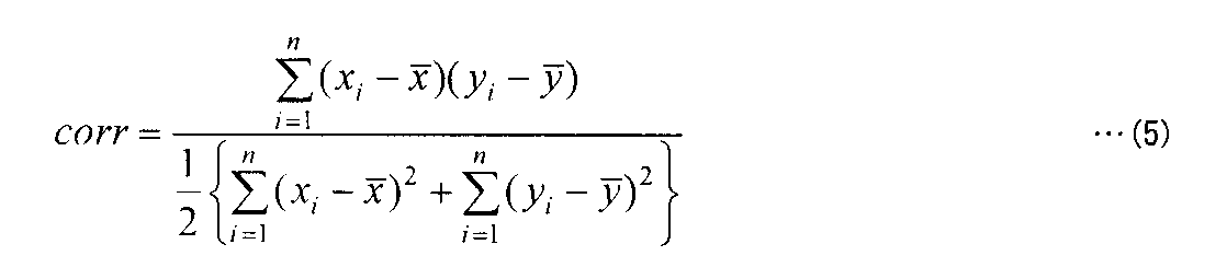
(x,y)が同一の信号源である場合には、相関係数corrは、自己相関係数と呼ぶ。異なる信号源を用いている場合には、相関係数corrは、相互相関係数と呼ぶ。
パケット検出部109は、自己相関係数を用いてパケットを検出できる。詳しくは、パケット検出部109は、N点前の自己の信号との相関係数を計算する。
図4を参照して、HomePlugAV規格に従って送信されるプリアンブルの構成について説明する。たとえば、HomePlugAV規格においては、パケット送信に先立ち、図4に示されるようなプリアンブルが送信される。プリアンブルのパターンは、周期5.12マイクロ秒(μs)で繰り返されるので、75MHzでサンプリングすると、384点ごとに類似した信号系列を受信するはずである。N=384、yi=xi-Nとし、式(5)と式(4)の条件が満たされた場合、パケット検出部109は、有効なPLC通信の信号を受信したと判定する。その判定に応答して、パケット検出部109は、状態遷移制御部110にパケット検出したことを通知する。
上記の説明に基づくパケット検出は、たとえば、3つの乗算器と少しの回路で実現できる。これは、少なくとも256個の乗算器を必要とするFFTと比べると、わずかな規模の回路である。
PLC上のパケットを検出するために必要なブロックは、アナログフロントエンド部105の受信系210とパケット検出部109だけであり、全体の回路から比べるとわずかな規模である。動作に影響のないブロック(アナログフロントエンド部105の送信系220、通信制御部106、イーサネット(登録商標)I/F107等)は、停止させてよい。
また、たとえば、IEEE802.11aの無線LANにおいては、ショート・プリアンブルで周期0.8μ秒の固定パターンの信号が10回繰り返される。したがって、パケット検出部109は、この期間中に無線パケット信号を検出することができる。
[ブロックの停止]
図5を参照して、電力線通信装置101における動作の停止について説明する。図5は、休止状態(A)と休止状態(B)とについてどのブロックを停止させるかをまとめたものである。
図5を参照して、電力線通信装置101における動作の停止について説明する。図5は、休止状態(A)と休止状態(B)とについてどのブロックを停止させるかをまとめたものである。
ここで、本実施の形態において、休止状態(A)とは、イーサネット(登録商標)のリンク・ダウンにより遷移する「休止状態」のことをいう。
本実施の形態において、休止状態(B)とは、PLC上の他の通信装置のすべてが休止状態であることを検出することにより遷移する「休止状態」のことをいう。ただし、WakeOnLANには対応しない。
ブロック(X)は、アナログフロントエンド部105の受信系210およびパケット検出部109を含む。ブロック(Y)は、通信制御部106、アナログフロントエンド部105の送信系220を含む。ブロック(Z)は、イーサネット(登録商標)I/F107および接続状態検出部108を含む。
図5において、「停止」させると書かれているブロックは、必ずしも停止させる必要はなく、一部、または全部を動作させていてもよい。電力線通信装置101の実装に応じて柔軟に選択してよい。また、図5において、「動作」させると書かれているブロックは、必ずしも常時動作させる必要はなく、間欠的に起き上がって動作させてもよい。間欠的に動作させると、一層の低消費電力化が実現できる。
[制御構造]
図6および図7を参照して、本実施の形態に係る電力線通信装置101の制御構造について説明する。図6は、休止状態(A)へ遷移する手順を表わすフローチャートである。図7は、休止状態(A)から通常動作状態に復帰する手順を表わすフローチャートである。
図6および図7を参照して、本実施の形態に係る電力線通信装置101の制御構造について説明する。図6は、休止状態(A)へ遷移する手順を表わすフローチャートである。図7は、休止状態(A)から通常動作状態に復帰する手順を表わすフローチャートである。
図6を参照して、電力線通信装置101が通常状態であるとき(ステップS101)、通信制御部106が、イーサネット(登録商標)通信のリンク・ダウンを検出すると(ステップS102)、ブロック(X)の動作とブロック(Y)の動作とを停止させる(ステップS103)。
ここで、各ブロックの動作の停止は、たとえば、電源供給の停止、または、クロック供給の停止等によって実現される。電源供給の停止は、具体的には、FET(Field Effect Transistor)を用いて、電源回路103にて変換された電源の供給を、オンとオフとの間で切り換えることである。または、他の局面において、スイッチング・レギュレータの出力そのものを停止させてもよい。
クロック供給の停止は、具体的には、ANDゲートなどを用いてクロックをマスクすることである。また、それ以外にも、IC(Integrated Circuit)チップに入力されるパワーダウン信号を制御する、リセット信号をかけ続ける、入力データ信号をマスクする等の方法もある。いずれの方法を用いてもかまわない。これらの制御は、当該処理を実現するように構成されたソフトウェアを実行させることにより実現される。
その後、電力線通信装置101は、通常の動作状態から休止状態(A)に遷移する旨を、その旨を表わすパケットをブロードキャストすることにより、ネットワークに接続されている他の通信装置に通知する(ステップS104)。ステップS104における通知は、他の通信装置にとって、ネットワーク管理という観点から有用なものであるが、本実施の形態においては、ステップS104の処理は、必ずしも必要ではない。その後、電力線通信装置101は、休止状態(A)へ遷移する(ステップS105)。休止状態(A)への遷移は、たとえば、ステップS103の処理から予め定められた時間の経過後に行なわれる。
図7を参照して、電力線通信装置101の状態が休止状態(A)であるとき(ステップS201)、通信制御部106は、イーサネット(登録商標)のリンク・アップを検出すると(ステップS202)、ブロック(X)の動作とブロック(Y)の動作とを再開する(ステップS203)。
その後、通信制御部106は、PLC上に任意のパケットを送信する(ステップS204)。ここで、送信されるパケットは特別なものでなくてよい。ネットワークを構成するための手順のひとつとしてパケットを送信する。
ステップS204で送信されるパケットは、前述している休止状態(B)へ遷移している通信装置があれば、それを起き上がらせるという役割がある。あるいは、他の局面において、ステップS204で送信されるパケットは、目覚ましパケットであってもよい。「目覚ましパケット」とは、PLC上で休止している通信装置を起こすためのものである。通信装置は、目覚ましパケットを受信すると、休止状態から、通常の待機状態にその動作状態を切り換える。また、休止状態(A)から復帰した通信装置は、伝送媒体上に他の通信装置がいないことを確認すると、適当な時間連続して「目覚ましパケット」を送信する。このようにすると、休止状態(B)へ遷移している通信装置が、定期的にしかパケット検出を行っていない場合でも、パケットをその間隔で検出できるため、即座に起き上がることができる。その後、電力線通信装置101は、通常の動作状態へ遷移する(ステップS205)。
図8は、電力線通信装置101が休止状態(B)へ遷移する手順を表わすフローチャートである。図9は、電力線通信装置101が通常の動作状態に復帰する手順を表わすフローチャートである。
図8を参照して、電力線通信装置101が通常の動作状態であるとき(ステップS301)、状態制御部110は、電力線通信装置101自身以外の通信装置すべてが休止状態(A)に遷移していることを検出すると(ステップS302)、ブロック(Y)の動作とブロック(Z)の動作とを停止する(ステップS303)。
より詳しくは、ステップS302において、状態遷移制御部110は、以下のような処理を実行する。他の通信装置が休止状態(A)に遷移する前に当該他の通信装置がその旨を示すパケットをブロードキャストする場合には、電力線通信装置101は、そのパケットを受信することで、他の通信装置が休止状態(A)であることを検出する。
または、次のように処理してもよい。すなわち、電力線通信装置101は、PLC上で無通信状態が一定時間以上続いていることを検出する。特に、PLCや無線の場合、チャンネル状況の変化により、まったく通信できなくなることもあり得る。このような場合に備えて、無通信状態が一定時間以上続いていることを電力線通信装置101が検出することは意味がある。その後、電力線通信装置101は、休止状態(B)へ遷移する(ステップS304)。電力線通信装置101が休止状態(B)に遷移すると、イーサネット(登録商標)I/F107を停止させ、その結果、イーサネット(登録商標)の接続状態をリンク・ダウンにさせている。
図9を参照して、電力線通信装置101の動作状態が休止状態(B)であるとき(ステップS401)、パケット検出部109は、PLC上にパケットを検出すると(ステップS402)、ブロック(Y)の動作とブロック(Z)の動作とを再開する(ステップS403)。
その後、電力線通信装置101は、通常の動作状態へ遷移する(ステップS404)。
以上のような構造およびフローチャートに基づく本実施の形態にかかる電力線通信装置101の動作を、図3を用いて説明する。なお、電力線通信装置101は、通信装置(R)303、通信装置(S)304、通信装置(T)306に対応するものとして説明する。
以上のような構造およびフローチャートに基づく本実施の形態にかかる電力線通信装置101の動作を、図3を用いて説明する。なお、電力線通信装置101は、通信装置(R)303、通信装置(S)304、通信装置(T)306に対応するものとして説明する。
PC305の電源をオフにする。通信装置(S)304とPC305との間のイーサネット(登録商標)接続状態がリンク・ダウンとなる。通信装置(S)304は、ネットワーク機器との接続状態が切断されていると判断し、その動作状態は、休止状態(A)に遷移する。このとき、通信装置(S)304は、休止状態(A)に遷移する旨を示すパケットをブロードキャストにより他の通信装置(R)303、通信装置(T)306に通知してもよい。
同様に、STB307の電源をオフにすると、通信装置(T)306の動作状態は、休止状態(A)に遷移する。
通信装置(R)303は、通信装置(S)304または通信装置(T)306が休止状態(A)に遷移したことを検出する。あるいは、通信装置(R)303は、PLC上で無通信状態が一定時間以上続いていることを検出する。その後、通信装置(R)303は、休止状態(B)に遷移する。
このとき、通信装置(R)303とルータ302との間のイーサネット(登録商標)の接続状態はリンク・ダウンとなるので、ルータ302も通常の動作モードから省電力モードに移行できる。
[機器の電源オン時]
その後、PC305の電源をオンにする。通信装置(S)304とPC305との間のイーサネット(登録商標)の接続状態は、リンク・アップとなる。通信装置(S)304は、ネットワーク機器との接続状態があると判断し、通常の動作状態に遷移する。このとき、通信装置(S)304は、ネットワークを構成するための手順のひとつとしてパケットを送信する。
その後、PC305の電源をオンにする。通信装置(S)304とPC305との間のイーサネット(登録商標)の接続状態は、リンク・アップとなる。通信装置(S)304は、ネットワーク機器との接続状態があると判断し、通常の動作状態に遷移する。このとき、通信装置(S)304は、ネットワークを構成するための手順のひとつとしてパケットを送信する。
通信装置(R)303は、PLC上でパケットを検出すると、通常の動作状態に遷移する。通信装置(R)303とルータ302との間のイーサネット(登録商標)の接続状態は、リンク・アップとなる。ルータ302は、リンク・アップを検出することにより、省電力モードから通常の動作モードに復帰する。なお、通信装置(T)306は、STB307の電源がオフである限り、休止状態(A)のままである。
以上により、通信装置を「休止状態」に遷移させる方法が示され、ネットワーク全体の消費電力を少なくする方法が示された。
<第2の実施の形態>
以下、第2の実施の形態について説明する。本実施の形態では、WakeOnLANに対応したネットワーク機器が混在した場合の「休止状態」への遷移方法を説明する。
以下、第2の実施の形態について説明する。本実施の形態では、WakeOnLANに対応したネットワーク機器が混在した場合の「休止状態」への遷移方法を説明する。
図10は、第2の実施の形態に係る電力線通信装置1000の構成の概略を表わす図である。なお、図1に示される構成要素と同じ構成要素には、同一の番号を付してある。それらの機能も同じである。したがって、同じ構成要素の説明は、繰り返さない。
電力線通信装置1000は、図1に示される電力線通信装置101の構成に加えて、パケット監視部111をさらに備える。パケット監視部111は、イーサネット(登録商標)I/F107と通信制御部106との間に配置され、ネットワーク機器150から送られるパケットを監視するように構成されている。なお、本実施の形態に係る電力線通信装置1000は、ネットワーク機器150へ送信するパケットを監視する必要はない。また、パケット監視部111からパケットを送信することはない。
通常、イーサネット(登録商標)I/F107と通信制御部106の間は、MII(Media Independent Interface)バスで接続されており、このバス接続によりパケットを監視することができる。
パケット監視部111は、通信制御部106とイーサネット(登録商標)インタフェース107との間を、パケットが流れているか否かを判定する、または、パケットが起動パケットであるかどうかを判定する。
パケット監視部111は、パケットが単に流れているか否かを判定するだけならば、接続状態検出部108と同様に、イーサネット(登録商標)I/F107であるイーサネット(登録商標)PHYまたはイーサネット(登録商標)・スイッチ・デバイスのアクティブ検出機能を利用することができる。特別な回路は不要である。この場合、パケット監視部111から外部割込み信号を通じて、通信制御部106内のCPUを起こしにいくことができる。
パケット監視部111は、パケットが起動パケットであるかどうかを判定するためには、通信制御部106とは別個の外部回路として、または、CPU上で動作するソフトウェアとして構成される必要がある。パケット監視部111は、通信制御部106とは別個の独立したCPUであってもよいし、あるいは、他の局面において、通信制御部106内に含まれるCPUであってもよい。ただし、パケット監視部111が通信制御部106内に含まれるCPU上で実現させるならば、通信制御部106のCPUは停止させてはならない。
図11は、電力線通信装置1000の動作状態が休止状態(C)と休止状態(D)であるとき、どのブロックを停止させるかの規定を表わす図である。ここで、「休止状態(C)」とは、イーサネット(登録商標)がリンク・アップ状態のままであるが、ネットワーク機器150からパケットを一定時間受信しなかった場合に遷移する「休止状態」のことをいう。たとえば、WakeOnLANに対応するネットワーク機器の電源がオフ(またはスタンバイ)である場合が想定される。
休止状態(D)とは、PLC上の他の通信装置のすべてが休止状態であることを検出することにより遷移する「休止状態」のことをいう。ただし、休止状態(B)とは違って、WakeOnLAN対応ネットワーク機器が混在している場合を考慮する。
また、ブロック(Z’)は、イーサネット(登録商標)I/F107、接続状態検出部108、パケット監視部111等を含む。
[制御構造]
図12および図13を参照して、第2の実施の形態に係る電力線通信装置1000の制御構造について説明する。図12は、第2の実施の形態に係る電力線通信装置1000が通常の動作状態から休止状態(C)へ遷移する手順を表わすフローチャートである。図13は、電力線通信装置1000が休止状態(C)から通常動作状態に復帰する手順を表わすフローチャートである。
図12および図13を参照して、第2の実施の形態に係る電力線通信装置1000の制御構造について説明する。図12は、第2の実施の形態に係る電力線通信装置1000が通常の動作状態から休止状態(C)へ遷移する手順を表わすフローチャートである。図13は、電力線通信装置1000が休止状態(C)から通常動作状態に復帰する手順を表わすフローチャートである。
電力線通信装置1000の動作状態が通常の動作状態であるとき(ステップS501)、イーサネット(登録商標)はリンク・アップ状態のままである。通信制御部106は、ネットワーク機器150からパケットを一定時間受信しなかった場合を検出すると(ステップS502)、ブロック(Y)の動作を停止する(ステップS503)。その後、通信制御部106は、電力線通信装置1000の動作状態が休止状態(C)に遷移する旨を示すパケットをブロードキャストする(ステップS504)。そのパケットの送信から予め定められた時間が経過すると、電力線通信装置1000の動作状態は、休止状態(C)へ遷移する(ステップS505)。
好ましくは、ステップS502において、通信制御部106は、ネットワーク機器150からある種のパケット(ここでは、BYEパケットと呼ぶ。)を受信したことを検出すると、休止状態(C)へ遷移してもよい。「BYEパケット」とは、ネットワーク機器150が電源オフ(またはスタンバイ)に移行するときに送出するパケットのことである。ネットワーク機器150によっては、このような「BYEパケット」が送出されることがある。具体的な例としては、UPnP(Universal Plug and Play)のSSDP(Simple Service Discovery Protocol)プロトコルの1つである、byebyeメッセージがある。「BYEパケット」を検出して休止状態(C)へ遷移する方法は、パケットを一定時間受信しないことを監視せずに済むため、時間がかからないという利点がある。
図13を参照して、電力線通信装置1000が休止状態(C)であるとき(ステップS601)、パケット監視部111がイーサネット(登録商標)から任意のパケットの受信を検出すると(ステップS602にてYES)、状態遷移制御部110は、ブロック(Y)の動作を再開する(ステップS603)。
その後、通信制御部106は、PLC上に任意のパケットを送信する(ステップS604)。ここで送信するパケットは、特別なものでなくてよい。通信制御部106は、ネットワークを構成するための手順のひとつとしてパケットを送信する。なお、ステップS604において送信されるパケットは、休止状態(B)または休止状態(D)である通信装置があれば、当該通信装置を起き上がらせるという役割がある。その後、電力線通信装置1000は、通常の動作状態へ遷移する(ステップS605)。
一方、パケット監視部111がイーサネット(登録商標)からのパケットの受信を検知しない場合において(ステップS602にてNO)、パケット検出部109がPLC上にパケットを検出すると(ステップS606にてYES)、状態遷移制御部110は、ブロック(Y)の動作を再開する(ステップS607)。その後、電力線通信装置1000は、通常の動作状態へ遷移する(ステップS608)。
それ以降、電力線通信装置1000は、通常の動作状態の一環として、PLCから受信したパケットをイーサネット(登録商標)の通信ネットワーク(たとえばネットワーク機器150)へ送信する。なお、PLCから受信したパケットが、起動パケットである場合には、そのパケットは、ネットワーク機器150を起動させる。
図14および図15を参照して、休止状態(D)への遷移と通常動作状態への復帰とについて説明する。図14は、電力線通信装置1000が休止状態(D)に遷移する手順を表わすフローチャートである。図15は、電力線通信装置が通常の動作状態に遷移するための手順を表わすフローチャートである。
図14を参照して、電力線通信装置1000の動作状態が通常の動作状態であるとき(ステップS701)、状態遷移制御部110は、電力線通信装置1000以外の全ての通信装置が「休止状態」に遷移し、そのうち1つ以上の通信装置が休止状態(C)に遷移した場合を検出すると(ステップS702)、ブロック(Y)を停止する(ステップS703)。
ステップS702における処理は、具体的には、以下のように実行される。まず、電力線通信装置1000以外の通信装置すべてが「休止状態」に遷移したことの検出は、以下のように行なわれる。他の通信装置が、休止状態に遷移する前に、その旨を示すパケットをブロードキャスト送信する場合には、電力線通信装置1000がそのパケットを受信することで、当該他の通信装置が「休止状態」に遷移したことを検出する。または、電力線通信装置1000は、PLC上の無通信状態が一定時間以上続いていることを検出すると、他の通信装置が「休止状態」であることを検出する。
次に、電力線通信装置1000が、複数の通信装置のうちの1つ以上の通信装置が休止状態(C)に遷移していることを検出するために、以下のような処理を実行する。すなわち、他の通信装置は、休止状態(C)に遷移する前に、その旨示すパケットをブロードキャスト送信するので、電力線通信装置1000は、そのパケットを受信することで、当該1つ以上の通信装置が休止状態(C)に遷移していることを検出する。その後、電力線通信装置1000は、休止状態(D)へ遷移する(ステップS704)。
図15を参照して、電力線通信装置1000が休止状態(D)であるときに(ステップS801)、パケット監視部111が、イーサネット(登録商標)の通信ネットワーク(たとえばネットワーク機器150)から起動パケットを受信したことを検出すると(ステップS802)、ブロック(Y)の動作を再開する(ステップS803)。
その後、通信制御部106は、PLC上に任意のパケットを送信する(ステップS804)。ここで、通信制御部106によって送信されるパケットは、特別なものではない。通信制御部106は、ネットワークを構成するための手順のひとつとして、パケットを送信する。なお、ステップS804で送信されるパケットは、休止状態(B)または休止状態(D)へ遷移している通信装置があれば、それを起動させるという役割がある。
その後、電力線通信装置1000は、通常の動作状態へ遷移する(ステップS805)。それ以降、電力線通信装置1000は、通常の動作の一環として、イーサネット(登録商標)から受信したパケットを、電源ユニット102を介して電力線に送信し、PLCが行なわれる。
なお、ステップS802において、判断の対象が起動パケットだけに限定されている理由は、ルータ302に接続された通信装置は、ルータ302から無用なパケットを受信することが多いからである。ここで、「無用なパケット」とは、電源オフ(またはスタンバイ)状態である(WakeOnLAN対応の)ネットワーク機器が起動するために無関係なパケットのことである。通信制御部106が、そのような「無用なパケット」をPLC上へ伝送すると、休止状態(C)へ遷移している通信装置は起き上がることになる。これは無駄な処理なので、本実施の形態では、起動パケット以外のパケットは伝送しないこととする。
「無用なパケット」の例は、たとえば、宛先アドレスがブロードキャスト・アドレスまたはマルチキャスト・アドレスで送信されるような制御パケットである。ルータ302が当該「無用なパケット」を送信する場合もあるし、ルータ302に接続された他のネットワーク機器(図示しない)が送信する場合もある。
一方、パケット監視部111が起動パケットを受信しなかった場合(ステップS802にてNO)、パケット検出部109は、PLC上にパケットを検出すると(ステップS806)、ブロック(Y)の動作を再開する(ステップS807)。電力線通信装置1000は、通常の動作状態へ遷移する(ステップS808)。
[起動パケット]
ここで、本実施の形態における起動パケットについて説明する。起動パケットとは、WakeOnLANに対応したネットワーク機器を起こすためのパケットをいう。したがって、起動パケットは、MACアドレス、IPアドレスその他のネットワーク機器を特定するための情報を含む。
ここで、本実施の形態における起動パケットについて説明する。起動パケットとは、WakeOnLANに対応したネットワーク機器を起こすためのパケットをいう。したがって、起動パケットは、MACアドレス、IPアドレスその他のネットワーク機器を特定するための情報を含む。
そこで、図16を参照して、本実施の形態に係る起動パケットの具体的構成の一例について説明する。図16は、起動パケットとして、マジックパケット1610、ARP(Address Resolution Protocol)パケット1620、ユニキャスト・パケット1630の構成の概略を表わす図である。
(1) マジックパケット1610の宛先アドレス(Destination Address)は、ブロードキャスト・アドレスであり、送信元アドレス(Source Address)は任意であり、送信プロトコルのタイプ(Type)は任意である。また、マジックパケット1610は、ペイロードとして、「ff:ff:ff:ff:ff:ff」と、ネットワーク機器のMACアドレスが16回繰り返し含まれたパケットである。
(2) ARPパケット1620の宛先アドレス(Destination Address)は、ブロードキャスト・アドレスであり、送信プロトコルはARPプロトコルであり、問い合わせIPアドレス(Target IP address)は、ネットワーク機器150のIPアドレスである。
(3) ユニキャスト・パケット1630の宛先アドレスは、ネットワーク機器のMACアドレスである。ただし、この例に限られず、(2)ARPパケットや(3)ユニキャスト・パケットを起動パケットの対象から外してもよいし、それ以外の種類のパケットを起動パケットの対象に加えてもよい。
パケット監視部111は、イーサネット(登録商標)I/Fから送られたパケットが図16に示されるようなパケットであるかどうかを調べ、起動パケットを特定する。したがって、パケット監視部111は、ターゲット機器(WakeOnLAN対応のネットワーク機器)のMACアドレスやIPアドレス情報を予め知っておく必要がある。そのため、ステップS504で、通信装置は、休止状態(C)に遷移する旨を通知するメッセージを送信するときに、その通信装置がブリッジしているネットワーク機器を特定する情報をそのメッセージに含めてもよい。ブリッジしているネットワーク機器が複数存在する場合には、パケットは、すべてのネットワーク機器を特定する情報を含むことが好ましい。
あるいは、PLC上で適切にネットワーク管理が行われているならば、リモートのブリッジ情報を利用してもよい。リモートのブリッジ情報とは、ブリッジしている通信装置の向こうに接続されたネットワーク機器の情報である。
図17は、ステップS104またはステップS504で送出される「休止状態に遷移する旨を通知するメッセージ」のフォーマットの例を示す図である。ここでは、メッセージ・フォーマットの一例として、HomePlugAV規格におけるベンダー独自のメッセージの形式を示す。
ODAは、メッセージの宛先アドレス(Original Destination Address)である。ここでは、ブロードキャスト・アドレスを設定する。OSAは、メッセージを送信する装置のアドレス(Original Source Address)を示す。
MTYPEは、EtherTypeを示す。ここでは、IEEEに割り当てられた番号を設定する。MMVは、メッセージのバージョンである。ここでは、HomePlugAV規格で定義された番号を設定する。
MMTYPEは、メッセージ識別番号である。ここでは、ベンダーが独自に定義できる範囲の中から選ぶ。たとえば、メッセージ識別番号「0xA100」を「休止状態(A)に遷移する」として、また、メッセージ識別番号「0xA104」を「休止状態(C)に遷移する」として、表わすように定義する。
OUIは、ベンダー識別番号(Vendor's OUI(Organizationally Unique Identifier))である。ここでは、IEEEに割り当てられた番号を設定する。BTEIは、メッセージを送信する装置の一時的な機器識別子(Bridging TEI(Temporary Equipment Identifier))である。
NBDAは、ブリッジしているネットワーク機器の数(Number of Bridged Destinations)である。BDAは、ブリッジしているネットワーク機器のアドレス情報(Bridged Destination Address)である。アドレス情報には、MACアドレスのみ、あるいは、MACアドレスとIPアドレスの両方が含まれる。BDAは、ブリッジしているネットワーク機器の数だけ存在する。
通信装置が休止状態(A)に遷移する場合は、ブリッジしているネットワーク機器のアドレス情報を省略してもよい。通信装置は、休止状態(A)または休止状態(C)に遷移するときに、図17のようなメッセージをブロードキャストで送信する。好ましくは、当該通信装置は、他の通信装置がより確実に受信できるようにするために、2回送信する。
[電力線通信装置の状態遷移]
図18を参照して、第2の実施の形態に係る電力線通信装置1000の状態の遷移について説明する。図18は、通常の動作状態と、各休止状態(A)~(D)との関係を表わす図である。
図18を参照して、第2の実施の形態に係る電力線通信装置1000の状態の遷移について説明する。図18は、通常の動作状態と、各休止状態(A)~(D)との関係を表わす図である。
遷移T1801は、電力線通信装置1000がイーサネット(登録商標)のリンク・ダウンを検出した時に(S102)、通常動作状態から休止状態(A)に遷移することを示す。遷移T1802は、電力線通信装置1000がイーサネット(登録商標)のリンク・アップを検出した時に(S202)、休止状態(A)から通常動作状態に遷移することを示す。遷移T1803は、電力線通信装置1000以外の通信装置全てが休止状態(A)に遷移した場合に(S302)、電力線通信装置1000が通常動作状態から休止状態(B)に遷移することを示す。遷移T1804は、電力線通信装置1000がPLC上にパケットを検出した場合に(S402)、休止状態(B)から通常動作状態に遷移することを示す。
遷移T1805は、イーサネット(登録商標)はリンクアップ状態のままであるが、電力線通信装置1000がネットワーク機器からパケットを一定時間受信しなかった場合に(S502)、通常動作状態から休止状態(C)に遷移することを示す。遷移T1806は、電力線通信装置1000がイーサネット(登録商標)から任意のパケットを受信した時(S602)、又は、PLC上にパケットを検出した時に(S606)、休止状態(C)から通常動作状態に遷移することを示す。遷移T1807は、電力線通信装置1000がイーサネット(登録商標)のリンクダウンを検出した場合に、休止状態(C)から休止状態(A)に遷移することを示す。
遷移T1808は、電力線通信装置1000の通信装置全てが「休止状態」に遷移し、そのうち1つ以上の通信装置が休止状態(C)に遷移した場合に(S702)、電力線通信装置1000が通常動作状態から休止状態(D)に遷移することを示す。遷移T1808は、電力線通信装置1000が、イーサネット(登録商標)から起動パケットを受信した場合に(S802)、または、PLC上にパケットを検出した場合に(S806)、休止状態(D)から通常動作状態に遷移することを示す。
[電力線通信装置1000の動作]
以上の構造およびフローチャートに基づく第2の実施の形態に係る電力線通信装置1000の動作を、図3を参照して説明する。なお、PC305は、WakeOnLANに対応しているものとし、STB307は、WakeOnLANに対応していないものとする。
以上の構造およびフローチャートに基づく第2の実施の形態に係る電力線通信装置1000の動作を、図3を参照して説明する。なお、PC305は、WakeOnLANに対応しているものとし、STB307は、WakeOnLANに対応していないものとする。
最初に、PC305の電源をオフ(またはスタンバイ)にする。通信装置(S)304とPC305との間のイーサネット(登録商標)の接続状態は、リンク・アップされたままである。
通信装置(S)304は、PC305からパケットを一定時間受信しなかったことを検出すると(S502)、休止状態(C)に遷移する。通信装置(S)304は、休止状態(C)に遷移する旨をブロードキャストで通知する。STB307の電源をオフにすると、通信装置(T)306は、そのオフを検知して、休止状態(A)に遷移する。
通信装置(R)303は、自身以外の全ての通信装置が休止状態に遷移したことを検出し、そのうち1つ以上の通信装置(たとえば通信装置(S)304)が休止状態(C)に遷移したことを検出する(S702)。この時点で、通信装置(R)303は、通信装置(S)304に接続されているネットワーク機器(たとえば、PC305)を特定する情報を把握している。この情報は、起動パケットの受信の有無を判断するために使用される。
その後、通信装置(R)303は、休止状態(D)に遷移する。通信装置(R)303とルータ302との間のイーサネット(登録商標)接続状態は、リンク・アップのまま維持される。以下、電力線通信装置1000の動作は、ケース1とケース2とに分かれる。
(ケース1)
しばらくして、ルータ302から、宛先がPC305であるパケットが送信され、通信装置(R)303は、そのパケットを受信する。このパケットは、起動パケットの受信の有無を判断するために使用される。通信装置(R)303は、PC305向けの起動パケットを受信したこと検出すると(S802)、通行の動作状態に復帰する。一方、通信装置(R)303は、それ以外のパケットを受信した場合には、無視する。その後、電力線通信装置1000は、通信制御部106の制御に基づいて、PLC上に任意のパケットを送信する。これにより、電力線通信装置1000を経由した通信が復活する。
しばらくして、ルータ302から、宛先がPC305であるパケットが送信され、通信装置(R)303は、そのパケットを受信する。このパケットは、起動パケットの受信の有無を判断するために使用される。通信装置(R)303は、PC305向けの起動パケットを受信したこと検出すると(S802)、通行の動作状態に復帰する。一方、通信装置(R)303は、それ以外のパケットを受信した場合には、無視する。その後、電力線通信装置1000は、通信制御部106の制御に基づいて、PLC上に任意のパケットを送信する。これにより、電力線通信装置1000を経由した通信が復活する。
通信装置(S)304は、PLC上にパケットを検出すると、通常動作状態に遷移する。しばらくして、電力線上の通信状態の準備が完了すると、電力線通信が可能な状態となる。通信装置(R)303は、電力線通信が可能となるまで、パケットを保持し続ける。通信装置(R)303は、電力線通信が可能になったことを検知すると、パケットをPC305宛てに送信する。このパケットは、通信装置(S)304によって受信される。通信装置(S)304は、通信装置(R)303からパケット(起動パケット)を受信すると、そのパケットをイーサネット(登録商標)へ伝送する。PC305は、起動パケットの受信に応答して、電源オフ(またはスタンバイ)の状態から通常の動作状態に復帰する。一方、通信装置(T)306は、STB307の電源がオフである限り、休止状態(A)のままである。
(ケース2)
しばらくして、(ユーザ操作により)PC305の電源がオンにされる。電源のオンに応答して、PC305は、ネットワークを構築するためのパケット(例えば、DHCP(Dynamic Host Configuration Protocol)パケットなど)を送出する。通信装置(S)304は、PC305によって送出された任意のパケットをイーサネット(登録商標)から受信すると、通常の動作状態に遷移する。その後、通信装置(S)304は、PLC上に当該任意のパケットを送信する。
しばらくして、(ユーザ操作により)PC305の電源がオンにされる。電源のオンに応答して、PC305は、ネットワークを構築するためのパケット(例えば、DHCP(Dynamic Host Configuration Protocol)パケットなど)を送出する。通信装置(S)304は、PC305によって送出された任意のパケットをイーサネット(登録商標)から受信すると、通常の動作状態に遷移する。その後、通信装置(S)304は、PLC上に当該任意のパケットを送信する。
通信装置(R)303は、PLC上にパケットを検出すると(S806)、通常の動作状態に遷移する。しばらくして、電力線上の通信状態が準備OKとなる。通信装置(S)304は、電力線上の通信状態が準備OKとなるまで、パケットを保持し続ける。
通信装置(R)303は、通信装置(S)304からパケットを受信すると、イーサネット(登録商標)のネットワークへそのパケットを伝送する。
通信装置(T)306は、STB307の電源がオフである限り、休止状態(A)のままである。
以上のようにして、電力線通信ネットワークにおいてWakeOnLANに対応したネットワーク機器が混在した場合にも、電力線通信装置1000を適切に「休止状態」に遷移させることができる。
詳述した上記の実施の各形態における伝送媒体は、たとえば、電力線である。しかしながら、本実施の形態に係る通信装置が適用される上で、伝送媒体は電力線に限られない。たとえば、無線LAN、同軸線、電話線などが用いられてもよい。
また、本実施の形態において、通信装置とネットワーク機器とはイーサネット(登録商標)で接続されているが、USB(Universal Serial Bus)、IEEE1394などであっても、本質的な差異はないと考えるべきである。イーサネット(登録商標)、USB、IEEE1394などでは、ケーブルの挿抜で、電圧レベルが変化するため、電気的に接続状態の有り/無しを判定できる。
また、本実施の形態における「ネットワーク」とは、電圧レベルの変化などを利用して、電気的に接続状態の有り/無しを判定できる性質を有し、また、接続機器側からインタフェースを停止させることによって、接続を切断させることができる性質を持つものであればよい。
この発明を詳細に説明し示してきたが、これは例示のためのみであって、限定ととってはならず、発明の範囲は添付の請求の範囲によって解釈されることが明らかに理解されるであろう。
101,1000 電力線通信装置、102 電源ユニット、103 電源回路、104 発振器、105 アナログフロントエンド部、106 通信制御部、107 イーサネット(登録商標)I/F、108 接続状態検出部、109 パケット検出部、110 状態遷移制御部、111 パケット監視部、150 ネットワーク機器、210 受信系、220 送信系、1051 受信フィルタ、1052 AGC、1053 A/D変換器、1054 D/A変換器、1055 送信フィルタ、1056 ライン・ドライバ、301 IP網、302 ルータ、303 通信装置(R)、304 通信装置(S)、305 PC、306 通信装置(T)、307 STB、308 TV。
Claims (17)
- 第1のネットワークの通信を第2のネットワークを用いて中継する通信装置であって、
前記第1のネットワークと前記通信装置との間の第1の通信インターフェイスと、
前記第2のネットワークと前記通信装置との間の第2の通信インターフェイスと、
前記通信装置の内部における動作の一部停止および再開を制御するための状態遷移制御部とを備え、
前記通信装置の動作状態が通常動作状態であるときに、
前記状態遷移制御部は、
前記第1のネットワーク上の機器との接続がないことを検出すると、前記第2の通信インターフェイスの動作を停止させることにより、前記通信装置の動作状態を、第1の休止状態に遷移させるように構成されており、
前記第2のネットワークに接続されている他の通信装置すべてが前記第1の休止状態にあることを検出すると、前記第1の通信インターフェイスの動作を停止させることにより、前記通信装置の動作状態を第2の休止状態に遷移させるように構成されている、通信装置。 - 前記通信装置は、前記第1の休止状態に遷移する直前に、前記第1の休止状態に遷移する旨のメッセージを前記第2のネットワーク上に送信するように構成されている、請求の範囲第1項に記載の通信装置。
- 前記第1のネットワーク上の機器との接続状態を検出するための接続状態検出部をさらに備え、
前記通信装置が前記第1の休止状態であるとき、
前記接続状態検出部が、前記通信装置と前記第1のネットワーク上の機器との接続があることを検出すると、前記状態遷移制御部は、前記通信装置を通常動作状態に遷移させるように構成されている、請求の範囲第1項または第2項に記載の通信装置。 - 前記第2のネットワーク上のパケットを検出するためのパケット検出部をさらに備え、
前記通信装置が前記第2の休止状態であるとき、前記パケット検出部が前記第2のネットワーク上のパケットを検出すると、前記状態遷移制御部は、前記通信装置を通常動作状態に遷移させるように構成されている、請求の範囲第1項から第3項のいずれか一項に記載の通信装置。 - 前記通信装置が通常動作状態であるとき、
前記状態遷移制御部は、
前記第1のネットワークに接続されている機器からパケットを予め定められた時間受信しなかったことを検出すると、
前記第1の通信インターフェイスの動作状態と前記第2の通信インターフェイスの動作状態とを維持したまま、前記通信装置における前記状態遷移制御部以外の内部回路の一部を停止させることにより、前記通信装置を第3の休止状態に遷移させるように構成されている、請求の範囲第1項から第4項のいずれか一項に記載の通信装置。 - 前記通信装置が通常動作状態であるとき、
前記状態遷移制御部は、
前記第1のネットワークに接続されている機器からBYEパケットを受信したことを検出すると、
前記第1の通信インターフェイスの動作状態と前記第2の通信インターフェイスの動作状態とを維持したまま、前記通信装置における前記状態遷移制御部以外の内部回路の一部を停止させることにより、前記通信装置を第3の休止状態に遷移させるように構成されている、請求の範囲第1項から第4項のいずれか一項に記載の通信装置。 - 前記通信装置は、前記第3の休止状態に遷移する直前に、前記第3の休止状態に遷移する旨のメッセージを前記第2のネットワークに送信するように構成されている、請求の範囲第5項または第6項に記載の通信装置。
- 前記第2のネットワーク上のパケットを検出するためのパケット検出部をさらに備え、
前記通信装置が前記第3の休止状態であるとき、前記パケット検出部が前記第2のネットワーク上のパケットを検出すると、前記状態遷移制御部は、前記通信装置の状態を通常動作状態に遷移させるように構成されている、請求の範囲第5項から第7項のいずれか一項に記載の通信装置。 - 前記第1のネットワーク上の機器から送信されたパケットを監視するためのパケット監視部をさらに備え、
前記通信装置が前記第3の休止状態であるとき、前記パケット監視部が前記第1のネットワーク上の機器からのパケットの受信を検出すると、前記状態遷移制御部は、前記通信装置を通常動作状態に遷移させるように構成されている、請求の範囲第5項から第8項のいずれか一項に記載の通信装置。 - 前記通信装置が通常動作状態のとき、
前記状態遷移制御部は、
前記第2のネットワークに接続されている他の通信装置のうち少なくとも1以上の通信装置が前記第3の休止状態にあり、他の残りの通信装置すべてが前記第1の休止状態にあること、を検出すると、
前記第1の通信インターフェイスの動作状態と前記第2の通信インターフェイスの動作状態とを維持したまま、前記通信装置における前記状態遷移制御部以外の内部回路の一部を停止させることにより、前記通信装置を第4の休止状態に遷移させるように構成されている、請求の範囲第5項から第9項のいずれか一項に記載の通信装置。 - 前記第2のネットワーク上のパケットを検出するためのパケット検出部をさらに備え、
前記通信装置が前記第4の休止状態であるとき、前記パケット検出部が前記第2のネットワーク上のパケットを検出すると、前記状態遷移制御部は、前記通信装置の状態を通常動作状態に遷移させるように構成されている、請求の範囲第10項に記載の通信装置。 - 前記第1のネットワーク上の機器から送信されたパケットを監視するためのパケット監視部をさらに備え、
前記通信装置が前記第4の休止状態であるとき、前記パケット監視部が前記第1のネットワーク上の機器から起動パケットを受信したことを検出すると、前記状態遷移制御部は、前記通信装置を通常動作状態に遷移させるように構成されている、請求の範囲第10項または第11項に記載の通信装置。 - 通信システムであって、請求の範囲第1項~第12項のいずれかに記載の通信装置が、前記第2のネットワークに接続されている、通信システム。
- 第1のネットワークの通信を第2のネットワークを用いて中継する通信装置の状態を遷移させるための方法であって、前記通信装置は、前記第1のネットワークと前記通信装置との間の第1の通信インタフェースと、前記第2のネットワークと前記通信装置との間の第2の通信インタフェースとを備えており、
前記方法は、
前記通信装置の動作状態が通常動作状態であるときに、前記第1のネットワーク上の機器との接続がないことを検出すると、前記第2の通信インタフェースの動作を停止させることにより、前記通信装置の動作状態を、第1の休止状態に遷移させるステップと、
前記第2のネットワークに接続されている他の通信装置すべてが前記第1の休止状態にあることを検出すると、前記第1の通信インタフェースの動作を停止させることにより、前記通信装置の動作状態を第2の休止状態に遷移させるステップとを含む、通信装置の状態遷移方法。 - 前記通信装置が前記通常動作状態であるとき、前記第1のネットワークに接続されている機器からパケットを予め定められた時間受信しなかったことを検出すると、前記第1の通信インタフェースの動作状態と前記第2の通信インタフェースの動作状態とを維持したまま、前記通信装置の内部回路の一部を停止させることにより、前記通信装置を第3の休止状態に遷移させるステップをさらに含む、請求の範囲第14項に記載の状態遷移方法。
- 前記通信装置が前記通常動作状態であるとき、前記第1のネットワークに接続されている機器からBYEパケットを受信したことを検出すると、前記第1の通信インタフェースの動作状態と前記第2の通信インタフェースの動作状態とを維持したまま、前記通信装置の内部回路の一部を停止させることにより、前記通信装置を第3の休止状態に遷移させるステップをさらに含む、請求の範囲第14項に記載の状態遷移方法。
- 前記通信装置が通常動作状態のとき、前記第2のネットワークに接続されている他の通信装置のうち少なくとも1以上の通信装置が前記第3の休止状態にあり、他の残りの通信装置すべてが前記第1の休止状態にあることを検出すると、前記第1の通信インタフェースの動作状態と前記第2の通信インタフェースの動作状態とを維持したまま、前記通信装置の内部回路の一部を停止させることにより、前記通信装置を第4の休止状態に遷移させるステップをさらに含む、請求の範囲第15項または第16項に記載の状態遷移方法。
Applications Claiming Priority (2)
| Application Number | Priority Date | Filing Date | Title |
|---|---|---|---|
| JP2008-171037 | 2008-06-30 | ||
| JP2008171037A JP4405567B2 (ja) | 2008-06-30 | 2008-06-30 | 通信装置、通信装置の状態遷移方法および通信システム |
Publications (1)
| Publication Number | Publication Date |
|---|---|
| WO2010001682A1 true WO2010001682A1 (ja) | 2010-01-07 |
Family
ID=41465785
Family Applications (1)
| Application Number | Title | Priority Date | Filing Date |
|---|---|---|---|
| PCT/JP2009/060232 Ceased WO2010001682A1 (ja) | 2008-06-30 | 2009-06-04 | 通信装置、通信装置の状態遷移方法および通信システム |
Country Status (2)
| Country | Link |
|---|---|
| JP (1) | JP4405567B2 (ja) |
| WO (1) | WO2010001682A1 (ja) |
Cited By (2)
| Publication number | Priority date | Publication date | Assignee | Title |
|---|---|---|---|---|
| CN103543815A (zh) * | 2012-07-09 | 2014-01-29 | 株式会社东芝 | 信息处理设备和信息处理方法 |
| EP2801901A1 (en) * | 2013-05-07 | 2014-11-12 | Buffalo Inc. | Network storage apparatus with bridge functionality |
Families Citing this family (6)
| Publication number | Priority date | Publication date | Assignee | Title |
|---|---|---|---|---|
| JP2011199761A (ja) * | 2010-03-23 | 2011-10-06 | Murata Machinery Ltd | ネットワーク装置、通信端末、ネットワークシステム、及びプログラム |
| JP5685858B2 (ja) * | 2010-08-27 | 2015-03-18 | ソニー株式会社 | カメラ装置、カメラシステム及びカメラ制御方法 |
| JP5453214B2 (ja) * | 2010-10-25 | 2014-03-26 | パナソニック株式会社 | 通信システム |
| JP2012114604A (ja) * | 2010-11-24 | 2012-06-14 | Nec Access Technica Ltd | 通信装置、通信方法、およびプログラム |
| JP5536681B2 (ja) | 2011-01-14 | 2014-07-02 | アラクサラネットワークス株式会社 | ネットワーク装置およびその制御方法、並びにコンピュータプログラム |
| JP5447450B2 (ja) | 2011-01-25 | 2014-03-19 | 株式会社デンソー | 通信装置 |
Citations (2)
| Publication number | Priority date | Publication date | Assignee | Title |
|---|---|---|---|---|
| JP2000201166A (ja) * | 1998-10-28 | 2000-07-18 | Matsushita Electric Ind Co Ltd | 省電力ネットワ―ク装置 |
| JP2003333070A (ja) * | 2002-03-12 | 2003-11-21 | Daimler Chrysler Ag | ネットワーク管理システム |
-
2008
- 2008-06-30 JP JP2008171037A patent/JP4405567B2/ja not_active Expired - Fee Related
-
2009
- 2009-06-04 WO PCT/JP2009/060232 patent/WO2010001682A1/ja not_active Ceased
Patent Citations (2)
| Publication number | Priority date | Publication date | Assignee | Title |
|---|---|---|---|---|
| JP2000201166A (ja) * | 1998-10-28 | 2000-07-18 | Matsushita Electric Ind Co Ltd | 省電力ネットワ―ク装置 |
| JP2003333070A (ja) * | 2002-03-12 | 2003-11-21 | Daimler Chrysler Ag | ネットワーク管理システム |
Cited By (2)
| Publication number | Priority date | Publication date | Assignee | Title |
|---|---|---|---|---|
| CN103543815A (zh) * | 2012-07-09 | 2014-01-29 | 株式会社东芝 | 信息处理设备和信息处理方法 |
| EP2801901A1 (en) * | 2013-05-07 | 2014-11-12 | Buffalo Inc. | Network storage apparatus with bridge functionality |
Also Published As
| Publication number | Publication date |
|---|---|
| JP4405567B2 (ja) | 2010-01-27 |
| JP2010011341A (ja) | 2010-01-14 |
Similar Documents
| Publication | Publication Date | Title |
|---|---|---|
| JP4405567B2 (ja) | 通信装置、通信装置の状態遷移方法および通信システム | |
| TWI429235B (zh) | 用於提供多媒體同軸聯盟功率管理策略的系統和方法 | |
| JP5445873B2 (ja) | デバイス発見期間におけるアクセスポイントの部分省電力モード | |
| US10609644B2 (en) | Low power receiver for wireless communication | |
| US9413549B2 (en) | Method for activating a network component of a motor vehicle network system | |
| US11775045B2 (en) | Managing power at a station via a physical layer device and related systems, methods and devices | |
| US8009695B2 (en) | System and method for dynamically swapping master and slave PHYs to allow asymmetry in energy efficient ethernet | |
| US8170624B1 (en) | Enhanced host sleep for WLAN devices | |
| KR101515546B1 (ko) | 에너지 효율을 향상시킨 차량용 전자 제어 장치 및 차량 네트워크 | |
| US20040224728A1 (en) | Method and system for power save mode in wireless communication system | |
| JP5662188B2 (ja) | 通信システム、トランシーバ、ノード | |
| US20140108840A1 (en) | Communication apparatus and control method therefor | |
| US9236909B2 (en) | Zero standby power for powerline communication devices | |
| JP2007259339A (ja) | 通信装置および通信装置の制御方法 | |
| JP2010278763A (ja) | 基地局装置 | |
| JP2010035209A (ja) | 通信装置および通信システム | |
| EP2471216A1 (en) | Network apparatus and method | |
| JP4295313B2 (ja) | 電力線通信装置及びその通信制御方法 | |
| US20240031181A1 (en) | Managing power state at a physical layer | |
| US11832177B2 (en) | Transmission system comprising first and second bridge devices | |
| Nordman et al. | Energy Efficiency and Regulation | |
| WO2013108134A2 (en) | Intelligent detection interface for wireless devices | |
| JP2005101827A (ja) | 受信装置および受信方法、プログラム、並びに記録媒体 |
Legal Events
| Date | Code | Title | Description |
|---|---|---|---|
| 121 | Ep: the epo has been informed by wipo that ep was designated in this application |
Ref document number: 09773260 Country of ref document: EP Kind code of ref document: A1 |
|
| NENP | Non-entry into the national phase |
Ref country code: DE |
|
| 122 | Ep: pct application non-entry in european phase |
Ref document number: 09773260 Country of ref document: EP Kind code of ref document: A1 |