WO2010001569A1 - 伝達比可変機構および可変比操舵装置 - Google Patents
伝達比可変機構および可変比操舵装置 Download PDFInfo
- Publication number
- WO2010001569A1 WO2010001569A1 PCT/JP2009/002966 JP2009002966W WO2010001569A1 WO 2010001569 A1 WO2010001569 A1 WO 2010001569A1 JP 2009002966 W JP2009002966 W JP 2009002966W WO 2010001569 A1 WO2010001569 A1 WO 2010001569A1
- Authority
- WO
- WIPO (PCT)
- Prior art keywords
- axis
- power transmission
- engageable
- shaft
- bearing
- Prior art date
- Legal status (The legal status is an assumption and is not a legal conclusion. Google has not performed a legal analysis and makes no representation as to the accuracy of the status listed.)
- Ceased
Links
Images


Classifications
-
- B—PERFORMING OPERATIONS; TRANSPORTING
- B62—LAND VEHICLES FOR TRAVELLING OTHERWISE THAN ON RAILS
- B62D—MOTOR VEHICLES; TRAILERS
- B62D5/00—Power-assisted or power-driven steering
- B62D5/008—Changing the transfer ratio between the steering wheel and the steering gear by variable supply of energy, e.g. by using a superposition gear
-
- F—MECHANICAL ENGINEERING; LIGHTING; HEATING; WEAPONS; BLASTING
- F16—ENGINEERING ELEMENTS AND UNITS; GENERAL MEASURES FOR PRODUCING AND MAINTAINING EFFECTIVE FUNCTIONING OF MACHINES OR INSTALLATIONS; THERMAL INSULATION IN GENERAL
- F16H—GEARING
- F16H1/00—Toothed gearings for conveying rotary motion
- F16H1/28—Toothed gearings for conveying rotary motion with gears having orbital motion
- F16H1/32—Toothed gearings for conveying rotary motion with gears having orbital motion in which the central axis of the gearing lies inside the periphery of an orbital gear
- F16H1/321—Toothed gearings for conveying rotary motion with gears having orbital motion in which the central axis of the gearing lies inside the periphery of an orbital gear the orbital gear being nutating
-
- Y—GENERAL TAGGING OF NEW TECHNOLOGICAL DEVELOPMENTS; GENERAL TAGGING OF CROSS-SECTIONAL TECHNOLOGIES SPANNING OVER SEVERAL SECTIONS OF THE IPC; TECHNICAL SUBJECTS COVERED BY FORMER USPC CROSS-REFERENCE ART COLLECTIONS [XRACs] AND DIGESTS
- Y10—TECHNICAL SUBJECTS COVERED BY FORMER USPC
- Y10T—TECHNICAL SUBJECTS COVERED BY FORMER US CLASSIFICATION
- Y10T74/00—Machine element or mechanism
- Y10T74/19—Gearing
- Y10T74/19642—Directly cooperating gears
- Y10T74/1966—Intersecting axes
Definitions
- the present invention relates to a transmission ratio variable mechanism and a variable ratio steering device.
- Patent Document 1 In a steering angle ratio variable steering device, it has been proposed to reduce noise by using a so-called Coriolis gear (for example, see Patent Document 1).
- a so-called Coriolis gear for example, see Patent Document 1
- an input gear and an output gear are arranged on both sides of a oscillating gear that performs so-called Coriolis motion, and mesh with the oscillating gear.
- An object of the present invention is to provide a small transmission ratio variable mechanism and variable ratio steering device that can suppress noise.
- preferred embodiments of the present invention include an input member that is rotatable about a first axis, an output member that is rotatable about the first axis, the input member, and the output member. And an intermediate member connecting the input member and the output member so as to allow the differential rotation.
- the intermediate member is rotatable around a second axis inclined with respect to the first axis.
- the input member includes a first power transmission surface, and the intermediate member includes a first power transmission surface facing the first power transmission surface of the input member.
- a plurality of first engageable portions are arranged on the first power transmission surface of the intermediate member along a first arrangement pitch circle centered on the second axis.
- a plurality of first engageable portions are arranged in an annular shape around the first axis on the first power transmission surface of the input member.
- the first engageable portion is engageable with the first engageable portion on a first engagement circle centered on the first axis.
- the output member includes a second power transmission surface
- the intermediate member includes a second power transmission surface facing the second power transmission surface of the output member.
- a plurality of second engageable portions are arranged on the second power transmission surface of the intermediate member along a second arrangement pitch circle centered on the second axis.
- a plurality of second engageable parts are arranged in an annular shape around the first axis on the second power transmission surface of the output member.
- the second engageable portion is engageable with the second engageable portion on a second engagement circle centered on the first axis.
- the diameter of the first array pitch circle and the diameter of the second array pitch circle are different from each other.
- the diameter of the first arrangement pitch circle related to the first engageable portion of the first power transmission surface with the second axis as the center, The diameters of the arrangement pitch circles related to the second engageable portion of the second power transmission surface are different from each other.
- the width of the intermediate member in the direction along the second axis can be reduced without increasing the inclination angle of the second axis.
- the diameter of the arrangement pitch circle related to the first engageable portion of the first power transmission surface and the second engageable portion of the second power transmission surface Since the diameters of the array pitch circles are different, the first and second power transmission surfaces can be easily discriminated in the intermediate member. Therefore, it is possible to prevent the intermediate member from being erroneously assembled.
- the electric motor further includes an electric motor for driving the intermediate member, and the electric motor includes an annular rotor disposed radially outward of the intermediate member, the following points are preferable. That is, as described above, since the width of the intermediate member in the direction along the second axis can be reduced, the rotor can be shortened in the axial direction. As a result, the inertia of the rotor can be reduced and the response of the electric motor can be improved.
- FIG. 3 is an enlarged view of a transmission ratio variable mechanism in FIG. 2 and its surroundings. It is the side view which represented a part of transmission ratio variable mechanism with the cross section. It is a disassembled perspective view of the principal part of an input member and an inner ring. It is sectional drawing of the 1st convex part and 1st recessed part which mutually mesh
- FIG. 1 is a schematic diagram showing a schematic configuration of a variable ratio steering apparatus 1 including a transmission ratio variable mechanism according to an embodiment of the present invention.
- a variable ratio steering apparatus 1 applies a steering torque applied to a steering member 2 such as a steering wheel to each of left and right steered wheels 4L and 4R via a steering shaft 3 as a steering shaft. Giving and turning.
- the variable ratio steering device 1 can change a transmission ratio ⁇ 2 / ⁇ 1 as a ratio (steering angle ratio) of the steering angle ⁇ 2 of the steered wheels 4L and 4R with respect to the steering angle ⁇ 1 of the steering member 2 (VGR). ) It has a function.
- the variable ratio steering device 1 includes a steering member 2 and a steering shaft 3 connected to the steering member 2.
- the steering shaft 3 includes first to third shafts 11 to 13 as first to third shafts arranged coaxially with each other.
- the first axis A1 as the central axis of the first to third shafts 11 to 13 is also the rotational axis of the first to third shafts 11 to 13.
- the steering member 2 is connected to one end of the first shaft 11 so as to be able to rotate together.
- the other end of the first shaft 11 and one end of the second shaft 12 are connected to each other so as to be differentially rotatable through a transmission ratio variable mechanism 5 as a steering angle ratio variable mechanism.
- the other end of the second shaft 12 and one end of the third shaft 13 are connected via a torsion bar 14 so that they can be elastically rotated relative to each other and can transmit power.
- the other end of the third shaft 13 is connected to the steered wheels 4L and 4R via the universal joint 7, the intermediate shaft 8, the universal joint 9, the steering mechanism 10, and the like.
- the steered mechanism 10 includes a pinion shaft 15 connected to the universal joint 9, and a rack shaft 16 as a steered shaft that has a rack 16a that meshes with the pinion 15a at the tip of the pinion shaft 15 and extends in the left-right direction of the vehicle. Yes.
- Knuckle arms 18L and 18R are connected to the pair of ends of the rack shaft 16 via tie rods 17L and 17R, respectively.
- the rotation of the steering member 2 is transmitted to the steering mechanism 10 via the steering shaft 3 or the like.
- the rotation of the pinion 15 a is converted into the axial movement of the rack shaft 16.
- the axial movement of the rack shaft 16 is transmitted to the corresponding knuckle arms 18L and 18R via the tie rods 17L and 17R, and the knuckle arms 18L and 18R rotate. Accordingly, the corresponding steered wheels 4L and 4R connected to the knuckle arms 18L and 18R are respectively steered.
- the transmission ratio variable mechanism 5 as the steering angle ratio variable mechanism is for changing the rotation transmission ratio (transmission ratio ⁇ 2 / ⁇ 1 as the steering angle ratio) between the first and second shafts 11 and 12 of the steering shaft 3. It is a nutation gear mechanism.
- the transmission ratio variable mechanism 5 includes an input member 20 provided at the other end of the first shaft 11 connected to the steering member 2 and an output provided at one end of the second shaft 12 as a steered wheel side member.
- the member 22 and the bearing ring unit 39 interposed between the input member 20 and the output member 22 are included.
- the input member 20 is connected to the steering member 2 and the first shaft 11 so as to be coaxial and rotatable together, and the output member 22 is connected to the second shaft 12 and coaxially rotatable.
- the first axis A ⁇ b> 1 is a central axis of the input member 20 and the output member 22, and is also a rotation axis of the input member 20 and the output member 22.
- the output member 22 is connected to the steered wheels 4L and 4R via the second shaft 12, the steered mechanism 10, and the like.
- the track ring unit 39 includes an inner ring 391 as a first track ring that provides an intermediate member, an outer ring 392 as a second track ring, and rolling elements 393 such as balls interposed between the inner ring 391 and the outer ring 392.
- the four-point contact bearing is configured.
- the rolling element 393 any of a cylindrical roller, a needle roller, and a tapered roller may be used.
- the bearing which the bearing ring unit 39 comprises may be a single row or a double row. If the bearings are arranged in double rows, the inner ring 391 can be prevented from falling down.
- An example of the double row bearing is a double row angular bearing.
- the inner ring 391 functions as an intermediate member that connects the input member 20 and the output member 22 so as to be differentially rotatable.
- the inner ring 391 and the outer ring 392 have a second axis A2 as a central axis inclined with respect to the first axis A1.
- the inner ring 391 is rotatably supported by an outer ring 392 as a second raceway ring via a rolling element 393. Therefore, as the transmission ratio variable motor 23, which is an electric motor as an actuator for driving the outer ring 392, can be rotated around the second axis A2, the first axis A1 It can be rotated around.
- the inner ring 391 and the outer ring 392 can perform Coriolis movement (swinging movement) around the first axis A1.
- the transmission ratio variable motor 23 is disposed radially outward of the track ring unit 39 with the first axis A1 of the track ring unit 39 as the center.
- the transmission ratio variable motor 23 changes the transmission ratio ⁇ 2 / ⁇ 1 as the steering angle ratio by changing the rotational speed of the outer wheel 392 around the first axis A1.
- the transmission ratio variable motor 23 is, for example, a brushless motor arranged coaxially with the steering shaft 3.
- the transmission ratio variable motor 23 includes a rotor 231 that holds the bearing ring unit 39 and a stator 232 that surrounds the rotor 231 and is fixed to the housing 24 as a steering column. The rotor 231 rotates around the first axis A1.
- the variable ratio steering device 1 includes a steering assist force applying mechanism 19 for applying a steering assist force to the steering shaft 3.
- the steering assist force applying mechanism 19 includes the second shaft 12 as an input shaft continuous with the output member 22 of the transmission ratio variable mechanism 5, the third shaft 13 as an output shaft continuous with the steering mechanism 10, A torque sensor 44 to detect torque transmitted between the second shaft 12 and the third shaft 13, a steering assist motor 25 as a steering assist actuator, a steering assist motor 25, and a third shaft. 13 and a speed reduction mechanism 26 interposed between them.
- the steering assist motor 25 is an electric motor such as a brushless motor.
- the output of the steering assist motor 25 is transmitted to the third shaft 13 via the speed reduction mechanism 26.
- the speed reduction mechanism 26 is composed of, for example, a worm gear mechanism, and is connected to the worm shaft 27 as a drive gear connected to the output shaft 25 a of the steering assist motor 25, meshed with the worm shaft 27, and rotatably connected to the third shaft 13. And a worm wheel 28 as a driven gear.
- the speed reduction mechanism 26 is not limited to the worm gear mechanism, and other gear mechanisms such as a parallel shaft gear mechanism using a spur gear or a helical gear may be used.
- the transmission ratio variable mechanism 5 and the steering assist force applying mechanism 19 are accommodated in a housing 24.
- the housing 24 is disposed in a passenger compartment (cabin) of the vehicle.
- the housing 24 may be disposed so as to surround the intermediate shaft 8 or may be disposed in the engine room of the vehicle.
- Driving of the transmission ratio variable motor 23 and the steering assist motor 25 is controlled by a control unit 29 including a CPU, a RAM, and a ROM, respectively.
- the control unit 29 is connected to the transmission ratio variable motor 23 via the drive circuit 40 and is connected to the steering assist motor 25 via the drive circuit 41.
- the control unit 29 includes a steering angle sensor 42 as a steering state detection sensor, a motor resolver 43 as a rotation angle detection means for detecting the rotation angle of the transmission ratio variable motor 23, a torque sensor 44 as a steering state detection sensor, A steered angle sensor 45, a vehicle speed sensor 46, and a yaw rate sensor 47 are connected to each other. Signals from the sensors 42 to 47 are input to the control unit 29. Specifically, a signal regarding the rotation angle of the first shaft 11 is input from the steering angle sensor 42 as a value corresponding to the steering angle ⁇ 1 that is the operation amount from the straight position of the steering member 2. Further, a signal regarding the rotation angle ⁇ r of the rotor 231 of the variable transmission ratio motor 23 is input from the motor resolver 43.
- a signal regarding the torque acting between the second and third shafts 12 and 13 is input as a value corresponding to the steering torque T acting on the steering member 2.
- a signal regarding the rotation angle of the third shaft 13 is input as a value corresponding to the turning angle ⁇ 2.
- a signal about the vehicle speed V is input from the vehicle speed sensor 46.
- a signal regarding the yaw rate ⁇ of the vehicle is input from the yaw rate sensor 47.
- the control unit 29 controls the drive of the transmission ratio variable motor 23 and the steering assist motor 25 based on the signals input from the sensors 42 to 47 and the like.
- the output of the transmission ratio variable mechanism 5 is transmitted to the steering mechanism 10 via the steering assist force applying mechanism 19. More specifically, the steering torque input to the steering member 2 is input to the input member 20 of the transmission ratio variable mechanism 5 via the first shaft 11, and further, the steering assist force applying mechanism 19 is output from the output member 22. Is transmitted to the second shaft 12.
- the steering torque transmitted to the second shaft 12 is transmitted to the torsion bar 14 and the third shaft 13, and together with the output from the steering assist motor 25, is transmitted to the steering mechanism 10 via the intermediate shaft 8 or the like. .
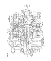
- FIG. 2 is a cross-sectional view showing a more specific configuration of the main part of FIG.
- the housing 24 is formed by forming a metal such as an aluminum alloy into a cylindrical shape, and includes a first housing 51, a second housing 52, and a third housing 53. It is out.
- a first bearing 31, a second bearing 32, a third bearing 33, a fourth bearing 34, a fifth bearing 35, a sixth bearing 36, a seventh bearing 37 and a first bearing 37 are provided.
- Eight bearings 38 are accommodated.
- the first to fifth bearings 31 to 35 and the seventh to eighth bearings 37 to 38 are rolling bearings such as angular ball bearings.
- the sixth bearing 36 is a rolling bearing such as a needle roller bearing.
- the first housing 51 has a cylindrical shape.
- the first housing 51 constitutes a differential mechanism housing that accommodates the transmission ratio variable mechanism 5 as a differential mechanism, and constitutes a motor housing that accommodates the transmission ratio variable motor 23.
- One end of the first housing 51 is covered with an end wall 54.
- One end of the first housing 51 and the end wall 54 are fixed to each other using a fastening member 55 such as a bolt.
- An annular convex portion 57 at one end of the second housing 52 is fitted to the inner peripheral surface 56 at the other end of the first housing 51.
- the first and second housings 51 and 52 are fixed to each other using a fastening member (not shown) such as a bolt.
- the second housing 52 has a cylindrical shape.
- the second housing 52 constitutes a sensor housing that accommodates the torque sensor 44 and also constitutes a resolver housing that accommodates the motor resolver 43.
- the second housing 52 accommodates a bus bar 99 described later of the transmission ratio variable motor 23 and a lock mechanism 58 for locking the rotor 231 of the transmission ratio variable motor 23.
- the inner peripheral surface 60 at one end of the third housing 53 is fitted to the outer peripheral surface 59 at the other end of the second housing 52.
- the third housing 53 has a cylindrical shape and constitutes a speed reduction mechanism housing that houses the speed reduction mechanism 26.
- An end wall portion 61 is provided at the other end of the third housing 53.
- the end wall portion 61 has an annular shape and covers the other end of the third housing 53.
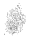
- FIG. 3 is an enlarged view of the transmission ratio variable mechanism 5 of FIG. 2 and its surroundings. Referring to FIG. 3, input member 20, output member 22 and inner ring 391 of variable transmission ratio mechanism 5 each have an annular shape.
- the input member 20 includes an input member main body 201 and a cylindrical member 202 that is disposed radially inward of the input member main body 201 and is connected to the input member main body 201 so as to be able to rotate together.
- the first shaft 11 is connected to the tubular member 202 so as to be able to rotate along with the tubular member 202 by being inserted through the insertion hole 202 a of the tubular member 202.
- the second shaft 12 is connected to the output member 22 so as to be able to rotate along with the output member 22 by passing through the insertion hole 22 a of the output member 22.
- the support mechanism 133 includes the cylindrical member 202 described above and the eighth bearing 38. That is, the cylindrical member 202 constitutes a part of the input member 20 and a part of the support mechanism 133.
- the cylindrical member 202 surrounds the opposing end portions 11a and 12a of the first and second shafts 11 and 12, respectively.
- One end of the cylindrical member 202 faces the first bearing 31 in the radial direction.
- the other end of the cylindrical member 202 is opposed to the opposed end portion 12a of the second shaft 12 in the radial direction.
- a bearing holding hole 109 is formed at the other end of the cylindrical member 202, and the opposed end portion 12 a of the second shaft 12 is inserted into the bearing holding hole 109.
- An eighth bearing 38 is interposed between the opposed end portion 12 a of the second shaft 12 and the bearing holding hole 109, and the eighth bearing 38 allows the tubular member 202 and the second shaft 12 to be relative to each other. Rotation is allowed.
- the 8th bearing 38 is connected with the opposing end part 11a of the cylindrical member 202 and the 1st shaft 11. It may be interposed between them.
- the inner ring 391 as an intermediate member is disposed radially outward of the cylindrical member 202.
- the outer ring 392 is held in an inclined hole 63 formed in the inner peripheral portion 233 of the rotor 231 of the variable transmission ratio motor 23 so as to be able to rotate together.
- the outer ring 392 and the rotor 231 rotate along with the first axis A1.
- the inclined hole 63 has the second axis A2 as the central axis.
- the race ring unit 39 performs Coriolis motion. *
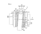
- FIG. 4 is a side view showing a part of the transmission ratio variable mechanism 5 in cross section. 3 and 4, the input member main body 201 and the inner ring 391 have annular first power transmission surfaces 70 and 71 that face each other in the axial direction S of the steering shaft 3, respectively.
- the first power transmission surface 70 of the input member main body 201 is provided with a first convex portion 65 as a first engageable portion, and a first power transmission composed of an end surface of an inner ring 391 as an intermediate member.
- the surface 71 is provided with a first recess 66 as a first engageable portion.
- the output member 22 and the inner ring 391 have annular second power transmission surfaces 72 and 73 that face each other in the axial direction S of the steering shaft 3.
- the second power transmission surface 72 of the output member 22 is provided with a second convex portion 68 as a second engageable portion, and a second power transmission consisting of the other end surface of the inner ring 391 as an intermediate member.
- the surface 73 is provided with a second recess 69 as a second engageable portion.
- a plurality of grooves 301 extending in the radial direction of the first power transmission surface 70 are radially arranged in the annular first power transmission surface 70 of the input member main body 201. They are arranged at equal intervals in the circumferential direction of the power transmission surface 70.
- a conical (or cylindrical) roller member 303 is fitted in each groove 301. A half portion of each roller member 303 protrudes from the groove 301, and the first protrusion 65 is configured by the protruding half portion.
- the roller member 303 may be a tapered roller having a reduced diameter as it goes inward in the radial direction of the input member 20, or may be a cylindrical roller.
- the total number of first convex portions 65 is, for example, 38.
- the total number of the first concave portions 66 is different from the total number of the first convex portions 65.
- a differential rotation can be generated between the input member main body 201 and the inner ring 391 according to the difference between the total number of the first protrusions 65 and the total number of the first recesses 66.
- the second axis A2 of the inner ring 391 is inclined at a predetermined angle B1 with respect to the first axis A1 of the input member 20, only a part of the plurality of first protrusions 65 (for example, several The first convex portion 65) and only a part of the plurality of first concave portions 66 (for example, several first concave portions 66) mesh with each other.
- the shapes of the groove 301 and the first recess 66 are simplified, but actually, as shown in FIG. 6, the cross-sectional shape of the groove 301 and the first recess 66 is a Gothic arc shape. (A shape in which two circular arcs having the same radius and different centers are connected).
- the roller member 303 constituting the first convex portion 65 is supported by the groove 301 and the first concave portion 66 in a four-point contact state.
- a grease reservoir 800 made of, for example, a groove is provided at the bottom of the groove 301 and the bottom of the first recess 66.
- grease can be sufficiently supplied from the grease reservoir 800 to the contact area between the roller member 303 and the groove 301 and the first recess 66, and wear and seizure of the contact area can be prevented over a long period of time. Can do.
- the grease reservoir 800 can be provided by arbitrarily setting the shape, depth, etc., as long as the position avoids the contact area.
- a plurality of grooves 302 extending in the radial direction of second power transmission surface 72 are arranged radially on second annular power transmission surface 72 of output member 22, so that second power
- the transmission surfaces 72 are arranged at equal intervals in the circumferential direction.
- Each groove 302 is fitted with a conical (may be cylindrical) roller member 304.
- a half portion of each roller member 304 projects from the groove 302, and the projecting half portion constitutes a second convex portion 68.
- a plurality of second recesses 69 extending in the radial direction of the second power transmission surface 73 are arranged radially, and the second power transmission surface 73 is arranged.
- the 2nd convex part 68 and the 2nd recessed part 69 are made into the substantially equal shape.
- the roller member 304 may be a tapered roller having a reduced diameter as it goes inward in the radial direction of the output member 22, or may be a cylindrical roller.
- the relationship between the total number of the second protrusions 68 and the total number of the second recesses 69 may be different from each other, for example, 38 and 40, or may be the same.
- the second axis A2 of the inner ring 391 is inclined at a predetermined angle B1 with respect to the first axis A1 of the output member 22, only a part of the plurality of second convex portions 68 (for example, several The second protrusion 68) and only a part of the plurality of second recesses 69 (for example, several second recesses 69) mesh with each other.
- the shapes of the groove 302 and the second recess 69 are simplified, but actually, the groove 301 and the first recess 66 shown in FIG. 6 are formed in the same Gothic arc shape as the cross-sectional shape.
- a grease reservoir 800 is provided.
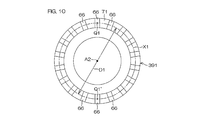
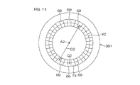
- the diameter D1 of the first arrangement pitch circle X1 (hereinafter referred to as the first arrangement pitch circle diameter D1) is an annular shape around the second axis A2 in the second power transmission surface 73 of the inner ring 391. This is different from the diameter D2 of the second array pitch circle X2 formed by the plurality of second recesses 69 arrayed in the following (hereinafter referred to as the second array pitch circle diameter D2). Specifically, the first arrangement pitch circle diameter D1 is larger than the second arrangement pitch circle diameter D2 (D1> D2).
- the diameter P1 of the first engagement circle Y1 centered on the first axis A1 (hereinafter referred to as the first engagement circle diameter P1) is the same as that of the inner ring 391.
- the first concave portion 66 of the first power transmission surface 71 engages with the first convex portion 65 of the corresponding first power transmission surface 70 of the input member 20 at an engagement point (corresponding to a meshing point) Q1. This is the diameter of the engagement circle (corresponding to the meshing circle).
- the diameter P2 of the second engagement circle Y2 centered on the first axis A1 (hereinafter referred to as the second engagement circle diameter P2) is equal to the inner ring 391.
- the second concave portion 69 of the second power transmission surface 73 engages with the second convex portion 68 of the second power transmission surface 72 of the corresponding output member 22 at an engagement point (corresponding to a meshing point) Q2. This is the diameter of the engagement circle (corresponding to the meshing circle).
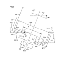
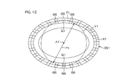
- FIG. 9 which is a schematic diagram, an inner ring 3911 before improvement having a relatively wide width W1 is shown by a broken line with respect to a direction parallel to the second axis A2, and with respect to a direction parallel to the second axis A2,
- An inner ring 391 of the present embodiment having a relatively narrow width W is shown by a solid line.
- the first array pitch circle diameter D11 related to the first recess 661 and the first array pitch circle diameter D21 related to the second recess 691 are equal to each other.
- the first array pitch circle diameter D1 related to the first recess 66 and the array pitch circle diameter D2 related to the second recess 69 are different from each other. Specifically, the first array pitch circle diameter D1 related to the first recess 66 is larger than the second array pitch circle diameter D2 related to the second recess 69 (D1> D2).
- the engagement point (engagement point) Q2 of the second recess 69 of the second power transmission surface 73 of the inner ring 391 of the present embodiment and the engagement point (engagement point) Q21 of the second recess 691 of the inner ring 3911 before improvement. Are both disposed on a cylinder having a second engagement circle diameter P2.
- the second The second array pitch circle diameter D2 related to the second recess 69 centered on the axis A2 is smaller than the second array pitch circle diameter D21 related to the second recess 691 before improvement (D2 ⁇ D21).
- the engagement point Q1 (see FIG. 8) of the first recess 66 of the first power transmission surface 71 of the inner ring 391 of the present embodiment is a point Q1 ′ that is in a symmetrical position with respect to the first axis A1, and is improved.
- the point of engagement of the first recess 661 of the front inner ring 3911 is a point Q11 ′ that is symmetric with respect to the first axis A1, both are disposed on a cylinder having the first engagement circle diameter P1. Yes.
- the second axis A2 The first array pitch circle diameter D1 related to the first recesses 66 centered on is made larger than the first array pitch circle diameter D11 related to the first recesses 661 before improvement (D1> D11).
- the rotor 231 of the transmission ratio variable motor 23 includes a cylindrical rotor core 85 extending in the axial direction S and a permanent magnet 86 fixed to the outer peripheral surface of the rotor core 85.
- the transmission ratio variable mechanism 5 and the torque sensor 44 as a steering state detection sensor are arranged inside the rotor core 85 in the radial direction.
- the rotor core 85 surrounds both the first convex portion 65 and the first concave portion 66 and the second convex portion 68 and the second concave portion 69 of the transmission ratio variable mechanism 5 over the entire circumference.
- the torque sensor 44 is surrounded over the entire circumference (in FIG.
- Examples of the material of the rotor core 85 include steel materials, aluminum alloys, clad materials, and resin materials. When a clad material that is a composite material in which a plurality of kinds of metals are bonded together is used, resonance can be suppressed. When a resin material is used for at least a part of the rotor core 85, the rotor inertia can be reduced by reducing the weight.
- a retained hole 87 is formed at one end of the rotor core 85.
- An annular bearing holding portion 88 is provided inside the held hole 87 in the radial direction. The bearing holding portion 88 is disposed on an annular convex portion 89 formed on the inner peripheral side of one end of the first housing 51. Since the second bearing 32 is interposed between the held hole 87 and the bearing holding portion 88, one end of the rotor core 85 is rotatably supported by the first housing 51.
- a held hole 90 is formed in an intermediate portion of the rotor core 85.
- An annular bearing holding portion 91 is provided inside the held hole 90 in the radial direction.
- the bearing holding portion 91 is disposed in an annular extending portion 92 formed on the inner peripheral side of one end of the second housing 52.
- the annular extending portion 92 has a cylindrical shape extending from the partition wall portion 93 provided at the other end of the second housing 52 to the one side S1 in the axial direction S, and the rotor core 85 is inserted therethrough.
- the fourth bearing 34 is interposed between the held hole 90 and the bearing holding portion 91, the intermediate portion of the rotor core 85 can rotate to the annular extending portion 92 of the second housing 52. It is supported.
- the rotor core 85 is supported at both ends by the second and fourth bearings 32 and 34 as a pair of bearings arranged with the bearing ring unit 39 sandwiched in the axial direction of the rotor 231.
- the permanent magnet 86 of the rotor 231 has different magnetic poles alternately in the circumferential direction C3 of the steering shaft 3, and N poles and S poles are alternately arranged at equal intervals in the circumferential direction C3.
- the permanent magnet 86 is fixed to the outer peripheral surface of the intermediate portion of the rotor core 85.
- the positions of the permanent magnet 86 and a part of the transmission ratio variable mechanism 5 in the axial direction S are overlapped with each other.
- the stator 232 of the transmission ratio variable motor 23 is accommodated in an annular first groove 94 formed at the other end of the first housing 51.
- the first groove 94 is open to the other side S2 in the axial direction S.
- the stator 232 includes a stator core 95 formed by laminating a plurality of electromagnetic steel plates and an electromagnetic coil 96.
- the stator core 95 includes an annular yoke 97 and a plurality of teeth 98 that are arranged at equal intervals in the circumferential direction of the yoke 97 and project inward in the radial direction of the yoke 97.
- the outer peripheral surface of the yoke 97 is fixed to the inner peripheral surface of the first groove portion 94 of the first housing 51 by shrink fitting or the like.
- An electromagnetic coil 96 is wound around each tooth 98.
- the bus bar 99 is arranged on the other side S2 in the axial direction S with respect to the stator 232.
- the bus bar 99 is housed in the second housing 52 in an annular shape as a whole, and is connected to each electromagnetic coil 96 of the transmission ratio variable motor 23.
- the bus bar 99 supplies power from the drive circuit to each electromagnetic coil 96.
- the positions of the bus bar 99 and the third and fourth bearings 33 and 34 with respect to the axial direction S are overlapped.
- a lock mechanism 58 is disposed on the other side S ⁇ b> 2 in the axial direction S with respect to the bus bar 99.
- the lock mechanism 58 is for restricting the rotation of the rotor 231 of the transmission ratio variable motor 23 and is accommodated in one end of the second housing 52.
- the lock mechanism 58 includes a regulated portion 100 coupled to the rotor core 85 so as to be able to rotate along with the rotor core 85, and a regulating portion 101 for regulating the rotation of the regulated portion 100 by engaging with the regulated portion 100.
- the regulated portion 100 is an annular member, and a recess 102 is formed on the outer peripheral surface.
- the recess 102 is formed at one or a plurality of locations in the circumferential direction of the regulated portion 100.
- the rotor core 85 may be provided with the recess 102. In this case, the rotor core 85 constitutes the restricted portion.
- a part of the regulated part 100 is overlapped with a part of the torque sensor 44 in the position in the axial direction S.
- the restricting portion 101 is disposed opposite to the restricted portion 100 in the radial direction of the restricted portion 100.
- the restricting portion 101 is held by the second housing 52 and can be moved to the restricted portion 100 side.
- a motor resolver 43 is arranged on the other side S ⁇ b> 2 in the axial direction S with respect to the lock mechanism 58.
- the motor resolver 43 is accommodated in a second groove 103 formed at the other end of the second housing 52, and is located radially outward of the rotor core 85.
- the second groove portion 103 is an annular groove defined by an annular outer peripheral portion 104 at one end of the second housing 52 and an annular extending portion 92.
- the second groove 103 communicates with the first groove 94.
- a housing space 139 for housing the transmission ratio variable motor 23, the lock mechanism 58, and the motor resolver 43 is defined by the first and second groove portions 94 and 103.
- the motor resolver 43 and the torque sensor 44 are opposed to each other in the radial direction R3 of the steering shaft 3. A part of the motor resolver 43 and a part of the torque sensor 44 are overlapped with each other in the axial direction S.
- the motor resolver 43 includes a resolver rotor 105 and a resolver stator 106.
- the resolver rotor 105 is fixed to the outer peripheral surface 107 at the other end of the rotor core 85 so as to be able to rotate together.
- the resolver stator 106 is press-fitted and fixed to the inner peripheral surface 108 of the outer peripheral portion 104 of the second housing 52.
- the first bearing 31 supports the input member 20 in a rotatable manner.
- the first shaft 11 is rotatably supported by the first housing 51 via the cylindrical member 202 of the input member 20 and the first bearing 31.
- the first bearing 31 is surrounded by the second bearing 32, and both positions are overlapped with respect to the axial direction S.
- the third bearing 33 is interposed between the bearing holding hole 110 formed in the inner peripheral portion at the tip of the extending portion 92 of the second housing 52 and the bearing holding portion 111 formed in the output member 22. Yes.
- the output member 22 is rotatably supported by the annular extending portion 92 of the second housing 52 via the third bearing 33.
- the third bearing 33 is surrounded by the fourth bearing 34, and both positions are overlapped with each other in the axial direction S.
- Preload is applied between the first convex portion 65 and the first concave portion 66 and between the second convex portion 68 and the second concave portion 69, respectively, and thereby the first convex portion.
- Smooth engagement between 65 and the first concave portion 66 and smooth engagement between the second convex portion 68 and the second concave portion 69 are possible.
- a screw member 113 is disposed on the inner peripheral portion 112 at one end of the first housing 51.
- the screw member 113 constitutes a biasing member that biases the input member main body 201 in a biasing direction H (corresponding to the other S2 side of the axial direction S) that brings the input member main body 201 closer to the output member 22.
- the screw member 113 constitutes a rigid member that rigidly supports the outer ring 312 of the first bearing 31 in the axial direction S.
- the screw member 113 urges the input member main body 201 toward the output member 22 so that the first convex portion 65 and the first concave portion 66 and the second convex portion 68 and the second concave portion 69 are urged. Preload is applied to each of
- the male screw portion 113 a formed on the outer peripheral surface of the screw member 113 is screwed into the female screw portion 134 a of the bearing holding hole 134 formed on the inner periphery of the annular convex portion 89 at one end of the first housing 51.
- the screw member 113 urges (presses) one end surface of the outer ring 312 of the first bearing 31 held in the bearing holding hole 134 of the first housing 51 in the urging direction H.
- the outer ring 312 of the first bearing 31 is rotatable with respect to the bearing holding hole 134 and is relatively movable in the axial direction S.
- a lock nut 135 is provided adjacent to the screw member 113. The lock nut 135 restricts the rotation of the screw member 113 in a state where the lock nut 135 is screwed into the female screw portion 134a.
- the inner ring 311 of the first bearing 31 is connected to the cylindrical member 202 so as to be able to rotate together with being press-fitted into one end of the cylindrical member 202.
- the inner ring 311 and the input member main body 201 can be rotated together and can be moved in the axial direction S.
- the inner ring 311 is in contact with one end portion of the input member main body 201 and presses the input member main body 201 in the urging direction H.
- first convex portion 65 is opposed to the first concave portion 66 in the urging direction H.
- second concave portion 69 faces the second convex portion 68 in the urging direction H.
- An inner ring 331 of a third bearing 33 is press-fitted and fixed to the output member 22.
- the output member 22 has a central stepped portion in contact with one end surface of the inner ring 331 and presses the inner ring 331 in the urging direction H.
- the outer ring 332 of the third bearing 33 is received by an annular stepped portion 114 disposed adjacent to the bearing holding hole 110 that holds the outer ring 332 so as to be movable in the urging direction H. Movement in the urging direction H is restricted.
- the movement of the output member 22 in the biasing direction H is regulated by the third bearing 33.
- the urging force of the screw member 113 is transmitted to the inner ring 311 via the outer ring 312 and the rolling element of the first bearing 31, and further to the input member main body 201.
- the urging force transmitted to the input member main body 201 is transmitted in the order of the first convex portion 65 and the first concave portion 66, and the second concave portion 69 and the second convex portion 68, and further the inner ring of the third bearing 33. 331, the rolling element and the outer ring 332.
- the urging force transmitted to the outer ring 332 of the third bearing 33 is received by the annular step portion 114.
- the rolling elements 393, the outer ring 392 and the rotor 231 of the transmission ratio variable motor 23 of the track ring unit 39 are biased. It moves in the direction H.
- the outer ring 392 of the track ring unit 39 is press-fitted and fixed in the inclined hole 63 of the rotor core 85.
- the rotor core 85 holds the outer ring 392 so as to be able to rotate along the first axis A1 and to move along the axial direction S.
- the outer rings 322 and 342 of the second bearing 32 and the fourth bearing 34 are loosely fitted in the corresponding annular held holes 87 and 90 of the rotor core 85, respectively, so that the rotor core 85 is relative to the axial direction S. Supports movable.
- the inner ring 321 of the second bearing 32 is press-fitted and fixed to the bearing holding portion 88 of the annular convex portion 89.
- the inner ring 341 of the fourth bearing 34 is press-fitted and fixed to the bearing holding portion 91 of the annular extending portion 92 of the second housing 52.
- the screw member 113 may be used to bias the output member 22 in a biasing direction (a direction opposite to the biasing direction H) in which the output member 22 approaches the input member main body 201.
- the screw member 113 is screwed into the bearing holding hole 110 that holds the third bearing 33.
- the biasing force of the screw member 113 includes the third bearing 33, the output member 22, the second convex portion 68 and the second concave portion 69, the first concave portion 66 and the first convex portion 65, the input member main body 201, the first convex portion 65, and the like.
- the inner ring 311, the rolling element and the outer ring 312 of one bearing 31 are transmitted in this order and received by the first housing 51.
- the movement of the inner ring 391 in the urging direction H is prevented from being hindered by the support mechanism 133.
- the outer ring 382 of the eighth bearing 38 of the support mechanism 133 is loosely fitted in the bearing holding hole 109 of the cylindrical member 202 and can be moved relative to the bearing holding hole 109 in the axial direction S.
- the inner ring 381 of the eighth bearing 38 is press-fitted and fixed to the opposed end portion 12 a of the second shaft 12.
- the outer ring 382 of the eighth bearing 38 may be press-fitted and fixed in the bearing holding hole 109, and the inner ring 381 may be loosely fitted to the facing end 12a.
- the torque sensor 44 is disposed radially inward of the rotor core 85 of the transmission ratio variable motor 23.
- the torque sensor 44 is supported by one end of the third shaft 13 and the multipolar magnet 115 fixed to the intermediate portion of the second shaft 12, and is disposed in the magnetic field generated by the multipolar magnet 115 to provide a magnetic circuit. And a pair of magnetic yokes 116 and 117 as soft magnetic bodies to be formed.
- the multipolar magnet 115 is a cylindrical permanent magnet, and a plurality of poles (the same number of N and S respectively) are magnetized at equal intervals in the circumferential direction.
- the magnetic yokes 116 and 117 are opposed to the multipolar magnet 115 with a predetermined gap in the radial direction of the multipolar magnet 115, and surround the multipolar magnet 115.
- Each of the magnetic yokes 116 and 117 is molded on a synthetic resin member 118.
- the synthetic resin member 118 is coupled to one end of the third shaft 13 so as to be able to rotate together.
- the torque sensor 44 further includes a pair of magnetism collecting rings 119 and 120 that guide magnetic flux from the magnetic yokes 116 and 117.
- the pair of magnetism collecting rings 119 and 120 are annular members formed using a soft magnetic material, surround the magnetic yokes 116 and 117, and are magnetically coupled to the magnetic yokes 116 and 117, respectively. .
- the pair of magnetism collecting rings 119 and 120 are separated from each other in the axial direction S and face each other.
- the magnetism collecting rings 119 and 120 are molded by the synthetic resin member 121.
- the synthetic resin member 121 is held by the annular extending portion 92 of the second housing 52.
- Magnetic flux is generated in the magnetic yokes 116 and 117 in accordance with the relative rotation amounts of the second and third shafts 12 and 13.
- This magnetic flux is induced by the magnetic flux collecting rings 119 and 120 and detected by a Hall IC (not shown) embedded in the synthetic resin member 121. Thereby, the magnetic flux density according to the torque applied to the second shaft 12 (steering member) can be detected.
- a fifth bearing 35 is arranged on the other side S ⁇ b> 2 in the axial direction S with respect to the torque sensor 44.
- the fifth bearing 35 is interposed between a bearing holding portion 122 formed on the outer periphery of one end of the third shaft 13 and a bearing holding hole 123 formed in the partition wall portion 93 of the second housing 52. Yes.
- the bearing holding hole 123 rotatably supports one end of the third shaft 13 through the fifth bearing 35.
- the third shaft 13 surrounds the second shaft 12 and the torsion bar 14. Specifically, an insertion hole 124 opened at one end of the third shaft 13 is formed in the third shaft 13. The other end of the second shaft 12 is inserted through the insertion hole 124. An insertion hole 125 extending in the axial direction S is formed in the second shaft 12, and the torsion bar 14 is inserted through the insertion hole 125.
- One end of the torsion bar 14 is connected to one end of the insertion hole 125 of the second shaft 12 so as to be able to rotate together by serration fitting or the like.
- the other end of the torsion bar 14 is connected to the insertion hole 124 of the third shaft 13 by serration fitting or the like so as to be able to rotate together.
- a radially inner space of the annular extending portion 92 of the second housing 52 is a torque sensor housing chamber 126, and a structure for suppressing the intrusion of the lubricant into the torque sensor housing chamber 126 is further provided. It has been.
- a third bearing 33 with a seal disposed at one end of the annular extending portion 92 of the second housing 52, an output member 22 disposed radially inward of the third bearing 33,
- One end of the torque sensor housing chamber 126 is closed by the second shaft 12 disposed radially inward of the output member 22.
- torque is generated by the fifth bearing 35 with seal, the third shaft 13 disposed radially inward of the fifth bearing 35, and the torsion bar 14 that closes the insertion hole 124 of the third shaft 13.
- the other end of the sensor chamber 126 is closed.
- the lubricant filled in the first recess 66, the second recess 69, the grooves 301 and 302, and the like can be prevented from entering the torque sensor housing chamber 126, and the speed reduction mechanism 26
- the lubricant filled in the meshing region of the worm shaft 27 and the worm wheel 28 can be prevented from entering the torque sensor housing chamber 126.
- the 2nd shaft 12 and the 3rd shaft 13 are mutually supported through the 6th bearing 36 so that relative rotation is possible.
- the sixth bearing 36 is surrounded by the worm wheel 28 of the speed reduction mechanism 26.
- the speed reduction mechanism 26 is accommodated in an accommodation chamber 128 defined by the outer peripheral portion 127 and the end wall portion 61 of the third housing 53 and the partition wall portion 93 of the second housing 52. A part of the worm wheel 28 and the sixth bearing 36 overlap with each other in the position in the axial direction S.
- a seventh bearing 37 is interposed between the intermediate portion of the third shaft 13 and the end wall portion 61 of the third housing 53.
- the end wall portion 61 supports the third shaft 13 via the seventh bearing 37 so as to be rotatable.
- the inner ring 371 of the seventh bearing 37 is sandwiched between an annular step 129 formed on the outer periphery of the third shaft 13 and a nut 130 screwed onto the outer periphery of the third shaft 13. .
- the outer ring 372 of the seventh bearing 37 is sandwiched between an annular step 131 formed in the third housing 53 and a retaining ring 132 held by the third housing 53.
- variable ratio steering device 1 Next, an example of the operation of the variable ratio steering device 1 will be described.
- the case where it is regulated and (iii) the case where the rotor 231 of the transmission ratio variable motor 23 is rotating and the input member 20 is rotating will be described.
- the total number of the first convex portions 65 is 38, the total number of the first concave portions 66 is 40, and the second convex portion 68 is used. It is assumed that the total number of the second recesses 69 is 40 and the total number of the second recesses 69 is 40.
- the rotation of the rotor 231 of the transmission ratio variable motor 23 is restricted by the lock mechanism 58, when the first shaft 11 is rotated by the operation of the steering member, the first of the input member main body 201 is changed.
- One convex portion 65 rotates around the first axis A1.
- the bearing ring unit 39 does not perform the Coriolis motion that rotates around the first axis A1, and only the inner ring 391 rotates around the second axis A2.
- the inner ring 391 provided with the first recess 66 is rotated, and the second shaft 12 is further rotated.
- the inner ring 391 rotates 38/40 when the input member 20 rotates once.
- the output member 22 rotates 38/40. That is, the rotation of the input member 20 is decelerated to 19/20.
- the rotor 231. Rotates around the first axis A1, whereby the bearing ring unit 39 performs a Coriolis motion.
- the inner ring 391 attempts to rotate the input member 20 and the output member 22 in the opposite directions. However, because the rotation of the input member 20 is restricted, only the output member 22 rotates.
- the output member The amount of rotation 22 is a value obtained by adding the amount of rotation of the input member 20 (steering member) to the amount of rotation of (ii) above.
- the transmission ratio ( ⁇ 2 / ⁇ 1) can be increased to reduce the amount of operation of the steering member 2 by the driver, and the vehicle can be steered.
- the steering angle ⁇ 1 and the yaw rate ⁇ of the vehicle are compared to determine the behavior of the vehicle.
- the rotation of the rotor 231 of the transmission ratio variable motor 23 is increased,
- the vehicle's stability control (posture stability control) is performed by decelerating.
- the driving of the rotor 231 of the variable transmission ratio motor 23 can be controlled so that the counter steer operation is performed.
- the second arrangement pitch circle diameter D2 related to the second recess 69 in the second power transmission surface 73 of the inner ring 391 are different from each other.
- the first engagement circle diameter P1 related to the first recess 66 of the first power transmission surface 71 centered on the first axis A1 and the second axis centered on the first axis A1.
- the width W of the inner ring 391 can be reduced.
- the engagement rate (engagement rate) of the first recess 66 and the first projection 65, and the engagement rate of the second recess 69 and the first projection 68 It is possible to suppress vibration and noise without reducing the meshing rate.
- the rotor 231 of the transmission ratio variable motor 23 surrounding the bearing ring unit 39 including the inner ring 391 as the intermediate member the input member 20 and the output member 22 can be shortened in the axial direction, the inertia of the rotor 231 is reduced.
- the response of the transmission ratio variable motor 23 can be improved. That is, the response of the transmission ratio variable motor 23 can be improved while suppressing vibration and noise.
- the first axis line A1 about the first axis A1 is adjusted.
- vibration and noise are further improved by improving the meshing rate of the first concave portion 66 and the first convex portion 65 and the meshing rate of the second concave portion 69 and the first convex portion 68. Can be reduced.
- first power transmission surface 71 and the second power transmission surface 73 of the inner ring 391 as an intermediate member, the first arrangement pitch circle diameter D1 related to the first recess 66 and the second related to the second recess 69. Since the arrangement pitch circle diameters D2 are different from each other, the first and second power transmission surfaces 71 and 73 of the inner ring 391 can be easily distinguished from each other. Therefore, it is possible to prevent erroneous assembly of the inner ring 391.
- the present invention is not limited to the above-described embodiment.
- the first recess as the first engageable portion on the first power transmission surface 70 of the input member 20A. 65A is provided, and the first convex portion 66A as the first engageable portion may be provided on the first power transmission surface 71 of the intermediate member 391A.
- a second recess 68A as a second engageable portion is provided in the second power transmission surface 72 of the output member 22A, and the second engagement is provided in the second power transmission surface 73 of the intermediate member 391A.
- a second convex portion 69 ⁇ / b> A as a possible portion may be provided.
- the input member main body 201 and the cylindrical member 202 may be integrally formed of a single material to constitute the input member.
- the intermediate member is the inner ring itself, but the intermediate member may be a member that rotates along with the inner ring.
- the intermediate member is an inner ring or a member that rotates together with the inner ring.
- the intermediate member may be an outer ring or a member that rotates together with the outer ring.
- the transmission ratio variable motor 23 drives the inner ring.
- SYMBOLS 1 Variable ratio steering apparatus, 2 ... Steering member, 3 ... Steering shaft, 4L, 4R ... Steering wheel, 5 ... Transmission ratio variable mechanism, 10 ... Steering mechanism, 11 ... 1st shaft, 12 ... 2nd shaft (Steering wheel side member), 20, 20A ... input member, 22,22A ... output member, 23 ... transmission ratio variable motor (electric motor), 231 ... rotor, 39 ... tracking wheel unit, 391,391A ... inner ring (intermediate) Member), 392 ... outer ring, 393 ... rolling element, 65 ... first convex part (first engageable part), 66 ... first concave part (first engageable part), 68 ...
- first arrangement pitch circle diameter diameter (diameter of first arrangement pitch circle), D2 ... second arrangement pitch circle diameter (second) P1... First engagement circle diameter (first engagement circle diameter), P2... Second engagement circle diameter (second engagement circle diameter), X1. 1st arrangement pitch circle, X2 ... 2nd arrangement pitch circle, Y1 ... 1st engagement circle, Y2 ... 2nd engagement circle
Landscapes
- Engineering & Computer Science (AREA)
- General Engineering & Computer Science (AREA)
- Mechanical Engineering (AREA)
- Chemical & Material Sciences (AREA)
- Combustion & Propulsion (AREA)
- Transportation (AREA)
- Power Steering Mechanism (AREA)
- Steering Control In Accordance With Driving Conditions (AREA)
- Retarders (AREA)
Priority Applications (2)
| Application Number | Priority Date | Filing Date | Title |
|---|---|---|---|
| EP09773147.5A EP2308742B1 (en) | 2008-06-30 | 2009-06-26 | Variable transmission ratio mechanism and variable ratio steering device |
| US13/001,722 US8281893B2 (en) | 2008-06-30 | 2009-06-26 | Variable transmission ratio mechanism and variable ratio steering device |
Applications Claiming Priority (2)
| Application Number | Priority Date | Filing Date | Title |
|---|---|---|---|
| JP2008-171132 | 2008-06-30 | ||
| JP2008171132A JP5218830B2 (ja) | 2008-06-30 | 2008-06-30 | 車両用操舵装置 |
Publications (1)
| Publication Number | Publication Date |
|---|---|
| WO2010001569A1 true WO2010001569A1 (ja) | 2010-01-07 |
Family
ID=41465676
Family Applications (1)
| Application Number | Title | Priority Date | Filing Date |
|---|---|---|---|
| PCT/JP2009/002966 Ceased WO2010001569A1 (ja) | 2008-06-30 | 2009-06-26 | 伝達比可変機構および可変比操舵装置 |
Country Status (4)
| Country | Link |
|---|---|
| US (1) | US8281893B2 (https=) |
| EP (1) | EP2308742B1 (https=) |
| JP (1) | JP5218830B2 (https=) |
| WO (1) | WO2010001569A1 (https=) |
Cited By (1)
| Publication number | Priority date | Publication date | Assignee | Title |
|---|---|---|---|---|
| CN107235070A (zh) * | 2016-03-28 | 2017-10-10 | 长城汽车股份有限公司 | 转向传动比控制方法和控制装置及转向系统和车辆 |
Families Citing this family (3)
| Publication number | Priority date | Publication date | Assignee | Title |
|---|---|---|---|---|
| US20110017005A1 (en) * | 2009-07-22 | 2011-01-27 | International Truck Intellectual Property Company, Llc | Reduced friction ring and pinion gear set |
| CA2863193C (en) * | 2012-11-13 | 2017-04-25 | National University Corporation Fukushima University | Crown gear deceleration mechanism |
| JP5968501B1 (ja) * | 2015-06-01 | 2016-08-10 | 三菱電機株式会社 | 車載電子制御装置 |
Citations (7)
| Publication number | Priority date | Publication date | Assignee | Title |
|---|---|---|---|---|
| JPS5939346U (ja) * | 1982-09-07 | 1984-03-13 | 有限会社大機製作所 | 高減速比を有する向斜面「ばい」歯車装置 |
| JP2006046405A (ja) * | 2004-08-02 | 2006-02-16 | Ogino Kogyo Kk | 変速歯車装置 |
| JP2006082718A (ja) | 2004-09-16 | 2006-03-30 | Toyoda Mach Works Ltd | 舵角比可変操舵装置 |
| JP2006088726A (ja) * | 2004-09-21 | 2006-04-06 | Ogino Kogyo Kk | 電動パワーステアリング装置 |
| JP2007170624A (ja) * | 2005-12-26 | 2007-07-05 | Toyota Motor Corp | 伝達比可変装置および車両操舵装置 |
| JP2008030747A (ja) * | 2007-09-11 | 2008-02-14 | Ogino Kogyo Kk | ステアリング装置 |
| JP2008171132A (ja) | 2007-01-10 | 2008-07-24 | Kawamura Electric Inc | 換気扇の警報装置 |
Family Cites Families (3)
| Publication number | Priority date | Publication date | Assignee | Title |
|---|---|---|---|---|
| JPH10184819A (ja) * | 1996-12-19 | 1998-07-14 | Namu:Kk | 変速歯車装置 |
| JP4699381B2 (ja) * | 2003-12-06 | 2011-06-08 | ツェットエフ、レンクジステメ、ゲゼルシャフト、ミット、ベシュレンクテル、ハフツング | 車両用重畳式操向システム |
| DE102004052562B3 (de) * | 2004-10-29 | 2006-02-09 | Thyssen Krupp Automotive Ag | Kraftfahrzeuglenkung mit Überlagerungsgetriebe |
-
2008
- 2008-06-30 JP JP2008171132A patent/JP5218830B2/ja not_active Expired - Fee Related
-
2009
- 2009-06-26 EP EP09773147.5A patent/EP2308742B1/en not_active Not-in-force
- 2009-06-26 US US13/001,722 patent/US8281893B2/en not_active Expired - Fee Related
- 2009-06-26 WO PCT/JP2009/002966 patent/WO2010001569A1/ja not_active Ceased
Patent Citations (7)
| Publication number | Priority date | Publication date | Assignee | Title |
|---|---|---|---|---|
| JPS5939346U (ja) * | 1982-09-07 | 1984-03-13 | 有限会社大機製作所 | 高減速比を有する向斜面「ばい」歯車装置 |
| JP2006046405A (ja) * | 2004-08-02 | 2006-02-16 | Ogino Kogyo Kk | 変速歯車装置 |
| JP2006082718A (ja) | 2004-09-16 | 2006-03-30 | Toyoda Mach Works Ltd | 舵角比可変操舵装置 |
| JP2006088726A (ja) * | 2004-09-21 | 2006-04-06 | Ogino Kogyo Kk | 電動パワーステアリング装置 |
| JP2007170624A (ja) * | 2005-12-26 | 2007-07-05 | Toyota Motor Corp | 伝達比可変装置および車両操舵装置 |
| JP2008171132A (ja) | 2007-01-10 | 2008-07-24 | Kawamura Electric Inc | 換気扇の警報装置 |
| JP2008030747A (ja) * | 2007-09-11 | 2008-02-14 | Ogino Kogyo Kk | ステアリング装置 |
Non-Patent Citations (1)
| Title |
|---|
| See also references of EP2308742A4 * |
Cited By (2)
| Publication number | Priority date | Publication date | Assignee | Title |
|---|---|---|---|---|
| CN107235070A (zh) * | 2016-03-28 | 2017-10-10 | 长城汽车股份有限公司 | 转向传动比控制方法和控制装置及转向系统和车辆 |
| CN107235070B (zh) * | 2016-03-28 | 2020-09-01 | 长城汽车股份有限公司 | 转向传动比控制方法和控制装置及转向系统和车辆 |
Also Published As
| Publication number | Publication date |
|---|---|
| JP5218830B2 (ja) | 2013-06-26 |
| US20110108356A1 (en) | 2011-05-12 |
| EP2308742A4 (en) | 2012-08-08 |
| EP2308742B1 (en) | 2013-08-21 |
| EP2308742A1 (en) | 2011-04-13 |
| JP2010006342A (ja) | 2010-01-14 |
| US8281893B2 (en) | 2012-10-09 |
Similar Documents
| Publication | Publication Date | Title |
|---|---|---|
| JP5234314B2 (ja) | 車両用操舵装置 | |
| JP5282938B2 (ja) | 伝達比可変機構およびこれを備える車両用操舵装置 | |
| CN101835672B (zh) | 传动比可变机构及具有该机构的车辆用操舵装置 | |
| JP5229543B2 (ja) | 車両用操舵装置 | |
| JP5218830B2 (ja) | 車両用操舵装置 | |
| JP5234313B2 (ja) | 車両用操舵装置 | |
| JP5224109B2 (ja) | 車両用操舵装置 | |
| JP5365833B2 (ja) | 車両用操舵装置 | |
| JP5158419B2 (ja) | 車両用操舵装置 | |
| JP5110361B2 (ja) | 伝達比可変機構およびこれを備える車両用操舵装置 | |
| JP5110362B2 (ja) | 伝達比可変機構およびこれを備える車両用操舵装置 | |
| JP5472686B2 (ja) | 車両用操舵装置 | |
| JP5397672B2 (ja) | 電動パワーステアリング装置 | |
| JP2010006341A (ja) | 車両用操舵装置 | |
| JP2010162947A (ja) | 揺動歯車装置、伝達比可変機構、および車両用操舵装置 | |
| JP2010060018A (ja) | 揺動型歯車装置、伝達比可変機構および車両用操舵装置 | |
| JP2010241343A (ja) | 電動パワーステアリング装置 |
Legal Events
| Date | Code | Title | Description |
|---|---|---|---|
| 121 | Ep: the epo has been informed by wipo that ep was designated in this application |
Ref document number: 09773147 Country of ref document: EP Kind code of ref document: A1 |
|
| WWE | Wipo information: entry into national phase |
Ref document number: 13001722 Country of ref document: US |
|
| NENP | Non-entry into the national phase |
Ref country code: DE |
|
| WWE | Wipo information: entry into national phase |
Ref document number: 2009773147 Country of ref document: EP |