WO2010001508A1 - 音声信号処理装置 - Google Patents
音声信号処理装置 Download PDFInfo
- Publication number
- WO2010001508A1 WO2010001508A1 PCT/JP2009/001384 JP2009001384W WO2010001508A1 WO 2010001508 A1 WO2010001508 A1 WO 2010001508A1 JP 2009001384 W JP2009001384 W JP 2009001384W WO 2010001508 A1 WO2010001508 A1 WO 2010001508A1
- Authority
- WO
- WIPO (PCT)
- Prior art keywords
- coefficient
- echo
- echo canceller
- coefficient update
- far
- Prior art date
- Legal status (The legal status is an assumption and is not a legal conclusion. Google has not performed a legal analysis and makes no representation as to the accuracy of the status listed.)
- Ceased
Links
Images


Classifications
-
- H—ELECTRICITY
- H04—ELECTRIC COMMUNICATION TECHNIQUE
- H04M—TELEPHONIC COMMUNICATION
- H04M1/00—Substation equipment, e.g. for use by subscribers
- H04M1/02—Constructional features of telephone sets
- H04M1/0291—Door telephones
-
- H—ELECTRICITY
- H04—ELECTRIC COMMUNICATION TECHNIQUE
- H04M—TELEPHONIC COMMUNICATION
- H04M9/00—Arrangements for interconnection not involving centralised switching
- H04M9/08—Two-way loud-speaking telephone systems with means for conditioning the signal, e.g. for suppressing echoes for one or both directions of traffic
- H04M9/082—Two-way loud-speaking telephone systems with means for conditioning the signal, e.g. for suppressing echoes for one or both directions of traffic using echo cancellers
Definitions
- the present invention relates to an audio signal processing apparatus that performs echo cancellation.
- an audio signal processing apparatus equipped with an echo canceller is used in an audio transmission system.
- one end of audio transmission is called the near end and the other end is called the far end.
- the far-end sound is transmitted as a far-end signal to the near-end side and is output from the near-end speaker.
- the near-end microphone receives a near-end signal, and the near-end signal is transmitted from the near-end side to the far-end side.
- an echo canceller is provided to cancel (cancel) the echo.
- echo cancellation is performed using an adaptive filter as described below.
- the far-end signal transmitted from the far-end side to the near-end side is supplied to the near-end speaker and input to the adaptive filter.
- the adaptive filter generates a pseudo echo signal from the far end signal by filtering.
- the pseudo echo signal is subtracted from the near-end signal input from the microphone.
- the echo canceller can cancel the echo from the near-end signal.
- the above adaptive filter is configured to update the filter coefficient in order to generate the same pseudo echo signal as the actual echo included in the near-end signal.
- the filter coefficient of the adaptive filter is referred to as an echo canceller coefficient.
- NLMS learning identification method
- w (k) is a coefficient vector (echo canceller coefficient) of the adaptive filter at time k.
- x (k) is an input signal (far end signal) vector to the adaptive filter at time k.
- ⁇ is a small constant for preventing the denominator term from becoming zero.
- ⁇ is the step size.
- e (k) is a residual signal obtained by subtracting the pseudo echo signal from the near-end signal at time k.
- the echo canceller is suitably provided in a drive-through system of a fast food restaurant.
- the customer side in drive-through is the near end side
- the store clerk side is the far end side.
- the clerk's voice is transmitted as a far-end signal and output from the near-end speaker.
- the voice uttered by the customer is input from the near-end microphone as a near-end signal and transmitted to the far-end side (store clerk).
- an echo is generated. This echo is preferably erased by an echo canceller.
- the convergence speed of the echo canceller coefficient can be set large.
- the convergence speed can be increased by setting a large step size.
- the convergence speed is increased, the post-convergence erasure process becomes unstable, and the echo erasure capability is reduced.
- the present invention has been made under the above-mentioned background, and an object thereof is to provide an audio signal processing apparatus capable of improving the echo cancellation capability when the near-end sound collection environment changes.
- the present invention outputs a far-end signal transmitted from a far-end side to a near-end side from a near-end speaker and transmits a near-end signal input from a near-end microphone to the far-end side.
- An echo canceller for canceling echo from the near-end signal input to the microphone based on the far-end signal supplied to the speaker, and the near-end side on which the speaker and the microphone are provided
- an environmental change detection unit that detects a change in the near-end sound collection environment that affects the acoustic transfer function in the echo canceller, an echo filter that generates a pseudo echo signal based on the far-end signal, and a filter coefficient of the adaptive filter
- a coefficient update control unit that converges the echo canceller coefficient by coefficient update processing, and the coefficient update control unit detects the change of the near-end sound collection environment when the environment change detection unit detects a change in the near-end sound collection environment.
- a far end signal transmitted from the far end side to the near end side is output from the near end side speaker, and a near end signal input from the near end side microphone is transmitted to the far end side.
- An audio signal processing method performed in an audio transmission system that performs echo cancellation processing for canceling echo from a near-end signal input to a microphone based on a far-end signal supplied to the speaker, and a speaker and a microphone Environment change detection processing that detects changes in the near-end sound collection environment that affect the acoustic transfer function on the near-end side, and echo cancellation processing is adaptive filter processing that generates a pseudo echo signal based on the far-end signal And a coefficient update control process for converging echo canceller coefficients, which are filter coefficients of the adaptive filter process, by the coefficient update process. When a change in the sound environment is detected, it changes the coefficient update processing to reduce the convergence speed of the echo canceller coefficients in accordance with the time after detection of changes in the near-end sound collection environment.
- the present invention includes a configuration for reducing the convergence rate of the echo canceller coefficient as time elapses after detection of a change in the near-end sound collection environment.
- the present invention can provide an audio signal processing apparatus having an effect of improving the echo cancellation capability when the near-end sound collection environment changes.
- FIG. 1 is a block diagram of an audio signal processing apparatus according to a first embodiment of the present invention.
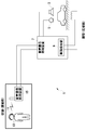
- FIG. 2 is a diagram illustrating an overall configuration of an audio transmission system including the audio signal processing device according to the first embodiment.
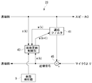
- FIG. 3 is a diagram showing the configuration of the echo canceller in the first embodiment.
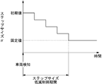
- FIG. 4 is a diagram showing step size change control.
- FIG. 5 is a diagram illustrating a configuration of the noise suppression unit according to the first embodiment.
- FIG. 6 is a diagram showing the operation of the echo canceller in the first embodiment.
- FIG. 7 is a diagram illustrating the operation of the noise suppression unit in the first embodiment.
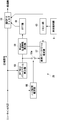
- FIG. 8 is a diagram showing the configuration of the echo canceller in the second embodiment.
- the present invention outputs a far-end signal transmitted from a far-end side to a near-end side from a near-end speaker and transmits a near-end signal input from a near-end microphone to the far-end side.
- An echo canceller for canceling echo from the near-end signal input to the microphone based on the far-end signal supplied to the speaker, and the near-end side on which the speaker and the microphone are provided
- an environmental change detection unit that detects a change in the near-end sound collection environment that affects the acoustic transfer function in the echo canceller, an echo filter that generates a pseudo echo signal based on the far-end signal, and a filter coefficient of the adaptive filter
- a coefficient update control unit that converges the echo canceller coefficient by coefficient update processing, and the coefficient update control unit detects the change of the near-end sound collection environment when the environment change detection unit detects a change in the near-end sound collection environment.
- the coefficient update process is changed so that the convergence rate of the echo canceller coefficient decreases as time elapses after the change in the near-end sound collection environment is detected. Is done. Therefore, immediately after the change in the near-end sound collection environment is detected, the coefficient convergence speed can be increased to increase the echo suppression speed. Then, the echo cancellation after convergence can be stabilized by decreasing the coefficient convergence speed according to the passage of time after detection. In this way, both the echo suppression speed (coefficient convergence speed) and the stability after convergence can be achieved, and the echo cancellation capability when the sound collection environment changes can be improved.
- the environment change detection unit may detect the arrival of the vehicle to the near end as a change in the near end sound collection environment.
- the echo processing capability can be improved in a drive-through system of a fast food restaurant.
- the convergence rate of the echo canceller coefficient can be suitably reduced as time elapses after detection of a change in the near-end sound collection environment.
- the echo suppression speed (coefficient convergence speed) and the stability after convergence are compatible, and the echo cancellation capability when the sound collection environment changes can be improved.
- the coefficient update control unit may be configured to be able to switch between a plurality of coefficient update processes with different convergence speeds, and a plurality of coefficients so that the convergence speed decreases as time elapses after detection of a change in the near-end sound collection environment.
- the update process may be switched.
- the coefficient update control unit may perform RLS coefficient update processing when a near-end sound collection environment change is detected, and then perform NLMS coefficient update processing.
- the echo canceller coefficient can be suitably controlled in accordance with the passage of time after detection of a change in the near-end sound collection environment. It is possible to improve both the echo suppression speed (coefficient convergence speed) and the stability after convergence, thereby improving the echo cancellation capability.
- the echo canceller coefficient can be suitably controlled according to the environment after the change by once clearing the echo canceller coefficient when the near-end sound collection environment changes. Therefore, the echo cancellation capability can be improved.
- the echo canceller may further include a cancel execution filter separate from the adaptive filter, and a coefficient transfer unit that transfers the echo canceller coefficient from the adaptive filter to the cancel execution filter.
- the coefficient transfer unit compares the echo cancellation effect of the adaptive filter and the cancellation execution filter, and cancels the echo canceller coefficient of the adaptive filter when the adaptive filter determines that the echo of the near-end signal is significantly canceled than the cancellation execution filter.
- the cancellation execution filter may perform echo cancellation using the echo canceller coefficient transferred from the adaptive filter.
- the echo canceller coefficient is transferred to the cancel execution filter when the coefficient update control unit calculates an echo canceller coefficient that significantly cancels the echo more than the cancel execution filter. Even if the coefficient update control unit calculates an echo canceller coefficient that does not significantly cancel the echo during coefficient convergence, coefficient transfer is not performed.
- the cancel execution filter can execute echo cancellation using an echo canceller coefficient that increases the echo suppression effect, and the stability of echo cancellation can be improved.
- This audio signal processing apparatus may include a noise suppression unit that suppresses near-end signal noise by learning noise in the near-end sound collection environment from the near-end signal.
- the noise suppression unit may reset noise learning before detection, or may newly start noise learning.
- a far end signal transmitted from the far end side to the near end side is output from the near end side speaker, and a near end signal input from the near end side microphone is transmitted to the far end side.
- An audio signal processing method performed in an audio transmission system that performs echo cancellation processing for canceling echo from a near-end signal input to a microphone based on a far-end signal supplied to the speaker, and a speaker and a microphone Environment change detection processing that detects changes in the near-end sound collection environment that affect the acoustic transfer function on the near-end side, and echo cancellation processing is adaptive filter processing that generates a pseudo echo signal based on the far-end signal And a coefficient update control process for converging echo canceller coefficients, which are filter coefficients of the adaptive filter process, by the coefficient update process.
- a change in the sound environment is detected, it changes the coefficient update processing to reduce the convergence speed of the echo canceller coefficients in accordance with the time after detection of changes in the near-end sound collection environment.
- a far end signal transmitted from the far end side to the near end side is output from the near end side speaker, and a near end signal input from the near end side microphone is transmitted to the far end side.
- a speech signal processing apparatus provided in the speech transmission system, wherein a noise suppression unit that suppresses noise in the near-end signal by learning noise in the near-end sound collection environment from the near-end signal; and An environment change detection unit that detects a change in a near-end sound collection environment that affects an acoustic transfer function on the near end side where the speaker and the microphone are provided, and the noise suppression unit includes the environment change detection unit When a change in the near-end sound collection environment is detected, noise learning before detection is reset and noise learning is newly started.
- FIG. 1 shows an audio signal processing apparatus according to a first embodiment of the present invention
- FIG. 2 shows an overall configuration of an audio transmission system including the audio signal processing apparatus of FIG.
- the audio transmission system 1 includes a customer-side speaker 3, a microphone 5, and an audio signal processing device 7, and a store clerk-side speaker 11, a microphone 13, and an audio signal processing device 15.
- the customer-side speaker 3 and microphone 5 are installed at an outdoor drive-through stop.
- the clerk-side speaker 11 and microphone 13 are attached to the clerk's head as a one-ear type headset.
- the audio signal processing device 7 includes a vehicle detection unit 9 as shown in the figure.
- the vehicle detection unit 9 detects that a vehicle has arrived at the drive-through stop location.
- the vehicle detection unit 9 is an example of the environment change detection unit of the present invention, and the environment change detection unit is configured to detect a change in the near-end sound collection environment that affects the acoustic transfer function on the near-end side. In drive-through, the near-end sound collection environment changes as the body changes. This environmental change is detected by the vehicle detection unit 9.
- FIG. 1 shows the configuration of the audio signal processing device 7 of the present embodiment.
- the audio signal processing device 7 includes an audio switch 21, an echo canceller 23, a noise suppression unit 25, and an echo suppressor 27, and also includes the vehicle detection unit 9 as described above.
- the voice switch 21 performs a switch operation so as to pass one of the far end signal and the near end signal.
- the far end signal passes through the echo canceller 23, is converted into an analog signal by the D / A converter 31, and is output from the speaker 3.
- the customer's voice is input from the microphone 5 and converted into a digital signal by the A / D converter 33.
- This digital audio signal passes through the echo canceller 23, the noise suppression unit 25, and the echo suppressor 27 as a near-end signal.
- the echo canceller 23 includes an adaptive filter as will be described later.
- the echo canceller 23 erases the echo from the near end signal by generating a pseudo echo signal using the far end signal.
- the noise suppression unit 25 is also composed of a filter.
- the noise suppression unit 25 performs noise learning to suppress the noise of the near-end signal.
- the echo suppressor 27 is composed of an attenuator.
- the echo suppressor 27 suppresses the echo remaining by the processing of the echo canceller 23.
- the near-end signal is processed in
- the vehicle detection unit 9 functions as an environment change detection unit of the present invention by detecting that a vehicle has arrived at a drive-through stop.
- a sensor coil is installed in the drive-through course. The vehicle is detected using the current flowing through the sensor coil when the vehicle arrives.
- the vehicle detection unit 9 supplies a vehicle detection signal indicating vehicle detection to the echo canceller 23 and the noise suppression unit 25 as information on detection of a change in the near-end sound collection environment.
- the far-end signal is transmitted from the far-end side to the near-end side and is output from the speaker 3 on the near-end side.
- this far-end signal goes around the microphone 5
- the far-end signal returns to the far-end side as an echo, which deteriorates the sound quality. Such an echo is erased by the echo canceller 23.
- the near-end signal is input to the subtracter 45 from the microphone 5 via the A / D converter 33, and the pseudo echo signal is input from the adaptive filter 41.
- the subtracter 45 subtracts the pseudo echo signal from the near-end signal, thereby canceling the echo from the near-end signal.
- the coefficient update control unit 43 controls the filter coefficient of the adaptive filter 41 so as to generate the same pseudo echo signal as the actual echo included in the near-end signal.
- the filter coefficient of the adaptive filter is called an echo canceller coefficient.
- the coefficient update control unit 43 repeatedly updates the echo canceller coefficient by learning processing, whereby the echo canceller coefficient converges, and the adaptive filter 41 can generate a pseudo echo signal that is substantially the same as the actual echo.
- the vehicle detection signal indicating the arrival of the vehicle is input from the vehicle detection unit 9 to the coefficient update control unit 43.
- the input of the vehicle detection signal means that the near-end sound collection environment has changed and the near-end acoustic transfer function has changed.
- the coefficient update control unit 43 needs to converge the echo canceller coefficient in accordance with the changed near-end sound collection environment and its acoustic transfer function. At this time, the coefficient update control unit 43 operates as follows.
- the coefficient update control unit 43 changes the coefficient update process so as to reduce the convergence speed of the echo canceller coefficient as time elapses after vehicle detection.
- the convergence speed is set high immediately after vehicle detection, and the echo canceller coefficient can be adjusted in a short period of time according to the near-end sound collection environment after vehicle detection. Then, the echo cancellation after convergence can be stabilized by reducing the convergence speed in accordance with the passage of time after detection.
- control of the coefficient convergence speed described above is realized, for example, by parameter control in one coefficient update process. Further, for example, the coefficient convergence speed can be controlled by switching a plurality of types of coefficient update processes having different convergence speeds. In the example of the present embodiment, parameter control is performed as described below.
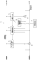
- FIG. 3 shows the configuration of the echo canceller 23 in more detail.
- the echo canceller 23 is configured to update the echo canceller coefficient by a learning identification method (NLMS method).
- the NLMS method repeatedly updates the echo canceller coefficient according to the following equation.
- w (k) is a coefficient vector (echo canceller coefficient) of the adaptive filter at time k
- x (k) is an input signal (far end signal) vector to the adaptive filter at time k.
- ⁇ is a small constant for preventing the denominator term from becoming zero.
- ⁇ is the step size.
- e (k) is a residual signal obtained by subtracting the pseudo echo signal from the near-end signal at time k.
- the far-end signal x is input to the coefficient update control unit 43.
- the residual signal e after passing through the subtracter 45 is input to the coefficient update control unit 43.
- the residual signal e is a signal obtained by subtracting a pseudo echo signal from the near-end signal.
- the current echo canceller coefficient w is input from the adaptive filter 41 to the coefficient update control unit 43.
- the coefficient update control unit 43 calculates the echo canceller coefficient of the next step from these input signals according to the calculation formula of the NLMS method, sends the calculated echo canceller coefficient to the adaptive filter 41, and updates the coefficient to the adaptive filter 41. To do.
- the coefficient update control unit 43 when a vehicle detection signal is input from the vehicle detection unit 9, the coefficient update control unit 43 once clears the echo canceller coefficient to zero. That is, the learning result before vehicle detection is discarded, and the coefficient update control unit 43 starts learning from the unlearned state.
- the reason for clearing the echo canceller coefficient is to adapt more quickly to a significant change in the near-end sound collection environment due to the arrival of the vehicle. Compared with the continuous use of the learning result before vehicle detection, the echo canceller coefficient converges more quickly to an appropriate value according to the environment after the change by starting learning from an unlearned state. Therefore, the echo canceller coefficient is cleared as described above.
- the coefficient update control unit 43 After clearing the echo canceller coefficient, the coefficient update control unit 43 repeatedly updates the echo canceller coefficient according to the formula of the NLMS method described above. At this time, the step size ⁇ is changed to be smaller as time passes after vehicle detection (after reset). The step size ⁇ is changed in a range of about 0 to 2, for example.
- FIG. 4 shows change control of the step size ⁇ .
- the step size ⁇ is set to a predetermined initial value and then reduced by a predetermined width.
- the step size ⁇ is reduced over a predetermined “step size reduction control period” and finally fixed at a predetermined fixed value.
- the step size ⁇ is changed a plurality of times.
- the step size ⁇ may be changed only once, that is, in two stages.
- the coefficient convergence speed can be variably controlled by changing the step size ⁇ .
- the initial value of the step size ⁇ is set to a predetermined relatively large value.
- the learning convergence speed can be increased.
- the step size ⁇ is changed to be smaller than the initial value after clearing (after detection) during convergence. This reduces the coefficient convergence speed, but provides high stability after convergence.
- the adaptive filter 41 and the coefficient update control unit 43 are configured to perform coefficient update when only the far-end signal includes speech. For this determination, the far-end signal and the near-end signal are input to the coefficient update control unit 43. Then, the far-end signal and the near-end signal are compared, and only the far-end person (clerk) is talking (the far-end signal includes the far-end voice, and the near-end signal includes the near-end voice. If not), the echo canceller coefficients are updated.
- the presence or absence of sound in the far-end signal is determined from the frequency spectrum. Further, the correlation between the far end signal and the near end signal is obtained. Specifically, the correlation is the similarity of the waveform of the frequency spectrum.
- the far-end signal includes speech. Note that this determination process is an example, and the same determination may be performed by another process.
- the echo canceller 23 may be configured to perform subband processing.
- the echo canceller 23 may be a DFT-SB-AEC (discrete Fourier transform subband acoustic echo canceller).
- the echo canceller 23 in the present embodiment has been described in detail above. Next, the detailed configuration of the noise suppression unit 25 (noise reduction) will be described.
- the microphone 5 is provided in the drive through, and the noise suppression unit 25 suppresses noise such as engine sound of the vehicle.
- the noise suppression unit 25 is configured to learn noise from the near-end signal.
- the vehicle detection signal is input not only to the echo canceller 23 but also to the noise suppression unit 25.
- the vehicle detection signal is input as information on changes in the near-end sound collection environment.
- the noise in the near-end signal changes.
- the noise suppression unit 25 is required to appropriately cope with the noise change.
- the noise suppression unit 25 resets noise learning before detection, clears filter coefficients for noise suppression, and newly starts noise learning. It is configured as follows.
- FIG. 5 shows the configuration of the noise suppression unit 25.
- the noise suppression unit 25 includes an adaptive FIR filter 51 for suppressing noise from the near-end signal.
- the filter coefficient of the adaptive FIR filter 51 is referred to as “noise suppression filter coefficient”.
- the noise suppression unit 25 further controls “FFT and power spectrum calculation unit 53”, “noise interval estimation unit 55”, “noise power spectrum estimation unit 57”, “wiener transfer characteristic calculation” in order to control the noise suppression filter coefficient.
- the noise suppression unit 25 includes a reset unit 63 as a configuration for resetting noise learning in response to vehicle detection by the vehicle detection unit 9.
- the FFT and power spectrum calculation unit 53 performs FFT (Fast Fourier Transform) on the near-end signal to convert a time-domain (time-axis) signal into a frequency-domain (frequency-axis) signal. Calculate the power spectrum.
- FFT Fast Fourier Transform
- the noise section estimation unit 55 estimates whether the near-end signal is a noise section signal or a voice section signal.
- the noise section is a section in which the near-end signal includes only the noise in the near-end environment without the sound being input from the microphone 5.
- the voice section is a section in which not only noise but also voice is included in the near-end signal.
- the noise section estimation unit 55 determines that the near-end signal is a voice section signal. If the parameter is smaller than the noise determination threshold, the noise section estimation unit 55 determines that the near-end signal is a noise section signal.
- the learned noise power spectrum is input to the Wiener transfer characteristic calculator 59. Also, the power spectrum of speech including noise is input from the FFT and power spectrum calculation unit 53 to the wiper transfer characteristic calculation unit 59.
- the wiper transfer characteristic calculation unit 59 obtains a transfer characteristic for noise suppression from the power spectrum of speech and the power spectrum of noise according to the following equation.
- H (w) is a value of the suppression transfer characteristic (wiener transfer characteristic) in the frequency domain.
- X (k) is a power spectrum of speech including noise.
- N (k) is the power spectrum of the learned noise.
- the vehicle detection signal corresponds to information indicating that the near-end sound collection environment has changed. If the near-end sound collection environment changes greatly due to the arrival of the vehicle, the learned value of the noise power spectrum deviates from the actual noise, and the noise suppression filter coefficient of the adaptive FIR filter 51 does not match the near-end sound collection environment. Therefore, when a change in the near-end sound collection environment is detected by the above processing, the noise suppression unit 25 resets noise learning before detection and newly starts noise learning. Accordingly, the noise learning estimation accuracy can be optimized in accordance with the changed near-end sound collection environment, that is, in a state where a new vehicle has arrived in the drive-through, and the noise suppression effect can be improved.
- the configuration of the audio signal processing device 7 of the present embodiment has been described above. Next, the operation of the audio signal processing device 7 will be described.
- the audio signal processing device 7 outputs the far end signal sent from the far end side from the speaker 3 and transmits the near end signal inputted from the microphone 5 to the far end side.
- the audio switch 21 performs a switch operation so that one of the far-end signal and the near-end signal passes therethrough.
- the far-end signal passes through the voice switch 21, is converted into an analog signal by the D / A converter 31, and is output from the speaker 3.
- the far end signal is input to the echo canceller 23.
- the echo canceller 23 erases the echo from the near-end signal input to the microphone 5 using the far-end signal.
- the near-end signal further passes through the noise suppression unit 25 and the echo suppressor 27. Noise is suppressed by the noise suppression unit 25.
- the echo suppressor 27 suppresses the echo remaining by the processing of the echo canceller 23.
- the near end signal is sent to the far end side through the voice switch 21.
- the echo canceller coefficient of the adaptive filter 41 is repeatedly updated by the coefficient update control unit 43.
- the coefficient update control unit 43 performs a learning process, whereby the echo canceller coefficients are converged to generate an appropriate pseudo echo signal. Specifically, the above-described learning identification method (NLMS) process is performed.
- NLMS learning identification method
- the echo canceller coefficient is maintained at an appropriate value, and the echo continues to be effectively erased.
- the speaker 3 and the microphone 5 are installed in the drive-through, and the near-end sound collection environment changes greatly when the vehicle arrives. Therefore, the echo canceller coefficient must be updated according to the near-end sound collection environment after the change.
- the customer speaks into the microphone 5 when the vehicle arrives. Therefore, the echo canceller coefficient needs to be updated to an appropriate value as soon as possible.
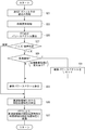
- the audio signal processing device 7 when the vehicle arrives, the audio signal processing device 7 operates as follows.
- step S7 the coefficient update control unit 43 performs coefficient update processing while reducing the step size ⁇ as time elapses from vehicle detection (step size initialization).
- step S7 the coefficient update control unit 43 performs the coefficient update process by applying the initial step size ⁇ to the NLMS equation.
- step S9 the coefficient update control unit 43 decrements the step size ⁇ by a predetermined width (S9), and determines whether or not a predetermined “step size reduction control period” has elapsed since vehicle detection (step size initialization). (S11). If the determination in step S11 is No, the coefficient update control unit 43 returns to step S7, applies the decremented step size ⁇ to the NLMS, and updates the echo canceller coefficient.
- the coefficient update control unit 43 repeats the coefficient update while decreasing the step size ⁇ by a predetermined width.
- step S11 When a predetermined step size reduction control period elapses from vehicle detection and the determination in step S11 becomes Yes, the coefficient update control unit 43 fixes the step size ⁇ to a predetermined fixed value, and applies the fixed value to the NLMS.
- the echo canceller coefficient is updated (S13). Therefore, the step size ⁇ is fixed until the current vehicle moves and the next vehicle is detected.
- FIG. 7 shows the operation of the noise suppression unit 25.
- the adaptive FIR filter 51 performs convolution processing of the FIR filter on the near-end signal using the noise suppression filter coefficient supplied from the IFFT unit 61, and the near-end signal
- the noise component is suppressed (S21), and the noise suppression filter coefficient update process is performed (S23).
- the near-end signal is input to the FFT and power spectrum calculation unit 53.
- the near end signal is converted from a time domain (time axis) signal into a frequency domain (frequency axis) signal by FFT (Fast Fourier Transform), and a power spectrum of the near end signal is calculated (S25).
- the near-end signal is input to the noise interval estimation unit 55.
- the noise section estimation unit 55 estimates whether the near-end signal is a noise section signal or a voice section signal (S27). When the determination result in step S27 is “noise”, the noise interval estimation unit 55 operates to supply the power spectrum to the noise power spectrum estimation unit 57 by closing the switch 55a.
- step S29 determines whether the vehicle detection signal is input to the reset unit 63.
- the reset unit 63 resets the learning data of the noise power spectrum estimation unit 57, clears the noise suppression filter coefficient of the adaptive FIR filter 51 (S31), and proceeds to step S33. Accordingly, in step S33, the noise power spectrum estimation unit 57 starts learning of the noise power spectrum using the noise power spectrum supplied from the FFT and the power spectrum calculation unit 53.
- the Wiener transfer characteristic calculation unit 59 processes the power spectrum of speech and the power spectrum of noise to calculate a suppression transfer characteristic in the frequency domain (S35).
- the determination in step S27 is “noise” and the noise power spectrum is learned in step S33, the learned noise power spectrum estimated value is used in step S35. If the determination in step S27 is “speech”, the current estimate of the noise power spectrum is used in step S35.
- the IFFT unit 61 converts the frequency domain suppression transmission characteristic into a time domain suppression transmission characteristic by inverse fast Fourier transform (S37). Filter processing and coefficient updating of the adaptive FIR filter 51 are performed using the suppression transmission characteristics after conversion. These processes correspond to steps S21 and S23 in the figure, and are performed in the following routine.
- the coefficient update control unit 43 of the echo canceller 23 is configured to perform the NLMS method (learning identification method) as the coefficient update process. Then, the coefficient update control unit 43 changes the coefficient update step size when the vehicle is detected, thereby reducing the coefficient convergence speed as time elapses.
- the coefficient update control unit 43 is configured to be able to switch between a plurality of coefficient update processes with different convergence speeds. And the coefficient update control part 43 switches a some coefficient update process so that learning convergence speed may fall according to the time passage after vehicle detection.
- the plurality of coefficient update processes are, for example, the NLMS method and the RLS method.
- the RLS (Recursive Least-Squares) method is also known as the coefficient update processing of the echo canceller.
- RLS is processing for obtaining an echo canceller coefficient so as to minimize the square error evaluation value related to input / output.
- a parameter called forgetting factor is used, and weighting is performed so that the value of the square error decreases as time goes back.
- the RLS method has a higher convergence speed, higher stability, and better performance.
- a fixed-point type DSP is often used as the echo canceller, and in this case, the accuracy is reduced by the RLS method. Therefore, when the RLS method and the NLMS method are compared, it can be said that the RLS method has a high convergence speed, and the NLMS method has high stability after convergence.
- the coefficient update control unit 43 clears the echo canceller coefficient (this clearing process is performed as described above). This is the same as the embodiment). Then, the coefficient update control unit 43 is configured to perform coefficient update processing of the RLS method, and subsequently perform coefficient update processing of the NLMS method. First, the echo canceller coefficient is updated by the RLS method for a predetermined time (a predetermined number of cycles). When the predetermined time has elapsed, the coefficient update control unit 43 switches the coefficient update process from the RLS method to the NLMS method, and updates the echo canceller coefficient by the NLMS method. When switching from the RLS method to the NLMS method, the echo canceller coefficient is carried over. By such coefficient control, immediately after vehicle detection, coefficient convergence is performed at high speed by the RLS method, and subsequently high stability after convergence is obtained by the NLMS method.
- the first embodiment of the present invention has been described above.
- the coefficient when a change in the near-end sound collection environment is detected, the coefficient so as to reduce the convergence rate of the echo canceller coefficient in accordance with the passage of time after the detection of the change in the near-end sound collection environment.
- the update process is changed. Therefore, immediately after a change in the near-end sound collection environment is detected, the convergence speed can be increased and the echo suppression speed can be increased. Then, the echo cancellation after convergence can be stabilized by reducing the convergence speed in accordance with the passage of time after detection. In this way, both the echo suppression speed (coefficient convergence speed) and the stability after convergence can be achieved, and the echo cancellation capability when the sound collection environment changes can be improved.
- the arrival of the vehicle to the near end side is detected as a change in the near end sound collection environment. Therefore, in an audio transmission system in which a vehicle arrives at the near end, it is possible to appropriately detect a change in the near end sound collection environment and improve the echo processing capability. In the above example, the echo processing capability can be improved in the drive-through system of a fast food restaurant.
- the convergence speed of the echo canceller coefficient is reduced by reducing the step size of the coefficient update process of the echo canceller coefficient as time elapses after detection of the change in the near-end sound collection environment.
- the learning identification method is changed so as to reduce the step size.
- the convergence rate of the echo canceller coefficient can be suitably reduced as time elapses after detection of a change in the near-end sound collection environment.
- the echo suppression speed (coefficient convergence speed) and the stability after convergence are compatible, and the echo cancellation capability when the sound collection environment changes can be improved.
- the echo canceller coefficient before detection is cleared.
- the echo canceller coefficient can be suitably controlled in accordance with the passage of time after the detection of the change in the near-end sound collection environment. It is possible to improve both the echo suppression speed (coefficient convergence speed) and the stability after convergence, thereby improving the echo cancellation capability.
- the coefficient update control unit 43 is configured to be able to switch between a plurality of coefficient update processes with different convergence speeds, and after detecting a change in the near-end sound collection environment The plurality of coefficient update processes are switched so that the convergence speed decreases as the time elapses.
- a plurality of types of coefficient update processing are switched, and accordingly, the convergence speed of the echo canceller coefficient can be suitably reduced as time elapses after detection of a change in the near-end sound collection environment.
- the echo suppression speed (coefficient convergence speed) and the stability after convergence are compatible, and the echo cancellation capability when the sound collection environment changes can be improved.
- RLS coefficient update processing may be performed, followed by NLMS coefficient update processing.
- the echo canceller coefficient can be suitably controlled in accordance with the passage of time after the detection of the change in the near-end sound collection environment. It is possible to improve both the echo suppression speed (coefficient convergence speed) and the stability after convergence, thereby improving the echo cancellation capability.
- the audio signal processing device 7 has the noise suppression unit 25 that suppresses the noise of the near-end signal by learning the noise in the near-end sound collection environment from the near-end signal.
- the noise suppression unit 25 resets noise learning before detection and newly starts noise learning.
- noise learning before detection is reset, and noise learning is newly started. Therefore, the estimation accuracy of noise learning can be optimized according to the near-end sound collection environment after the change, and the noise suppression effect can be improved.
- the audio signal processing apparatus provided with the noise suppression unit described above can also be realized in an audio signal processing apparatus that does not include the above-described echo canceller convergence speed control function.
- FIG. 8 shows an echo canceller 71 provided in the audio signal processing apparatus of the present embodiment.
- the echo canceller 71 has a twin filter configuration including an adaptive filter 73 and a cancel execution filter 75.
- a coefficient transfer unit 77 is provided.
- the coefficient transfer unit 77 is configured to transfer the echo canceller coefficient from the adaptive filter 73 to the cancel execution filter 75.
- the adaptive filter 73 functions to adjust the echo canceller coefficient. Actual echo cancellation is performed by a cancel execution filter 75.
- the cancel execution filter 75 is a filter that can change the filter coefficient. Upon receiving the echo canceller coefficient from the coefficient transfer unit 77, the cancel execution filter 75 sets the received echo canceller coefficient as a filter coefficient and uses it. Until the next echo canceller coefficient is transferred, the cancel execution filter 75 uses the echo canceller coefficient fixed.
- the far end signal is input to the cancel execution filter 75 in the same manner as the adaptive filter 73.
- the cancellation execution filter 75 performs filtering on the far-end signal using the echo canceller coefficient transferred from the adaptive filter 73, generates a pseudo echo signal, and supplies the pseudo echo signal to the second subtracter 83. Similar to the first subtractor 81, the near-end signal is input to the second subtractor 83.
- the second subtracter 83 subtracts the pseudo echo signal from the near end signal. This residual signal is transmitted to the far end side as a near end signal from which echoes have been eliminated.
- the coefficient transfer unit 77 compares these two residual signals. As a result, the coefficient transfer unit 77 compares the echo cancellation effects of the adaptive filter 73 and the cancel execution filter 75 to determine whether the adaptive filter 73 cancels the echo significantly more than the cancellation execution filter 75. Specifically, the coefficient transfer unit 77 compares the two residual signals to determine the magnitude relationship. If the residual signal from the first subtracter 81 is smaller, the residual signal obtained by canceling the echo using the adaptive filter 73 is smaller. In this case, the coefficient transfer unit 77 determines that the adaptive filter 73 significantly cancels the echo. Then, the coefficient transfer unit 73 transfers the echo canceller coefficient of the adaptive filter 73 to the cancel execution filter 75 when the adaptive filter 73 significantly cancels the echo.
- the above significance determination and coefficient transfer are performed when the far-end signal includes speech and the near-end signal does not include the speech of the speaker at the near end. More specifically, as shown in FIG. 8, the far-end signal and the near-end signal are input to the coefficient transfer unit 77.
- the coefficient transfer unit 77 compares the far-end signal and the near-end signal, and only the far-end signal includes the voice (the far-end signal includes the far-end voice and the near-end signal does not include the near-end voice. Judgment).
- This determination may be the same as the determination made by the coefficient updating unit in the first embodiment. That is, the presence or absence of sound in the far-end signal is determined from the frequency spectrum. Further, the correlation between the far end signal and the near end signal is obtained.
- the correlation is the similarity of the waveform of the frequency spectrum. If speech is present in the far-end signal and the similarity between the far-end signal and the near-end signal is equal to or higher than a predetermined level, only the far-end signal includes speech.
- the far-end signal is output from the speaker 3 (FIG. 1) and supplied to the adaptive filter 73 and the cancel execution filter 75.
- the adaptive filter 73 cooperates with the coefficient update control unit 79 and the first subtracter 81 to perform a learning operation for generating an appropriate pseudo echo signal.
- the cancellation execution filter 75 uses the echo canceller coefficient transferred from the adaptive filter 73 by the coefficient transfer unit 77 as a fixed coefficient to generate a pseudo echo signal from the far-end signal.
- the first subtracter 81 subtracts the pseudo echo signal generated by the adaptive filter 73 from the near-end signal.
- the second subtracter 83 subtracts the pseudo echo signal generated by the cancel execution filter 75 from the near end signal.
- the output of the first subtracter 81 is input to the coefficient update control unit 79 for coefficient update, and is also supplied to the coefficient transfer unit 77.
- the output of the second subtracter 83 is transmitted to the far end side (more specifically, the next noise suppression unit) and also input to the coefficient transfer unit 77.
- the adaptive filter 73 and the cancel execution filter 75 are provided.
- the coefficient update control unit 79 calculates an echo canceller coefficient that significantly cancels the echo more than the cancel execution filter 75, the echo canceller coefficient is transferred to the cancel execution filter 75. Even if the coefficient update control unit 79 calculates an echo canceller coefficient that does not significantly cancel the echo during coefficient convergence, coefficient transfer is not performed.
- the cancellation execution filter 75 can execute echo cancellation using an echo canceller coefficient that increases the echo suppression effect, and the stability of echo cancellation can be improved.
- the convergence speed is first set high, and then the convergence speed is reduced.
- the echo canceller coefficients are sequentially transferred to the cancel execution filter 75.
- coefficient transfer is suppressed. If an echo canceller coefficient that increases the echo suppression effect is calculated, coefficient transfer is performed again. Thus, a more effective echo cancellation coefficient can be used.
- the audio signal processing apparatus has an effect of improving the echo canceling ability when the near-end sound collection environment is converted.
- the present invention is useful as an audio signal processing apparatus such as a drive-through in a fast food restaurant.
Landscapes
- Engineering & Computer Science (AREA)
- Signal Processing (AREA)
- Circuit For Audible Band Transducer (AREA)
- Telephone Function (AREA)
Applications Claiming Priority (2)
| Application Number | Priority Date | Filing Date | Title |
|---|---|---|---|
| JP2008-173816 | 2008-07-02 | ||
| JP2008173816A JP4991649B2 (ja) | 2008-07-02 | 2008-07-02 | 音声信号処理装置 |
Publications (1)
| Publication Number | Publication Date |
|---|---|
| WO2010001508A1 true WO2010001508A1 (ja) | 2010-01-07 |
Family
ID=41465618
Family Applications (1)
| Application Number | Title | Priority Date | Filing Date |
|---|---|---|---|
| PCT/JP2009/001384 Ceased WO2010001508A1 (ja) | 2008-07-02 | 2009-03-27 | 音声信号処理装置 |
Country Status (2)
| Country | Link |
|---|---|
| JP (1) | JP4991649B2 (cg-RX-API-DMAC7.html) |
| WO (1) | WO2010001508A1 (cg-RX-API-DMAC7.html) |
Cited By (24)
| Publication number | Priority date | Publication date | Assignee | Title |
|---|---|---|---|---|
| CN109285554A (zh) * | 2017-07-20 | 2019-01-29 | 阿里巴巴集团控股有限公司 | 一种回声消除方法、服务器、终端及系统 |
| CN109756822A (zh) * | 2017-11-01 | 2019-05-14 | 通用汽车环球科技运作有限责任公司 | 使用传递函数估计的有效回波消除 |
| US10367948B2 (en) | 2017-01-13 | 2019-07-30 | Shure Acquisition Holdings, Inc. | Post-mixing acoustic echo cancellation systems and methods |
| USD865723S1 (en) | 2015-04-30 | 2019-11-05 | Shure Acquisition Holdings, Inc | Array microphone assembly |
| CN113168840A (zh) * | 2018-11-30 | 2021-07-23 | 松下知识产权经营株式会社 | 翻译装置以及翻译方法 |
| USD944776S1 (en) | 2020-05-05 | 2022-03-01 | Shure Acquisition Holdings, Inc. | Audio device |
| US11297423B2 (en) | 2018-06-15 | 2022-04-05 | Shure Acquisition Holdings, Inc. | Endfire linear array microphone |
| US11297426B2 (en) | 2019-08-23 | 2022-04-05 | Shure Acquisition Holdings, Inc. | One-dimensional array microphone with improved directivity |
| US11303981B2 (en) | 2019-03-21 | 2022-04-12 | Shure Acquisition Holdings, Inc. | Housings and associated design features for ceiling array microphones |
| US11302347B2 (en) | 2019-05-31 | 2022-04-12 | Shure Acquisition Holdings, Inc. | Low latency automixer integrated with voice and noise activity detection |
| US11310596B2 (en) | 2018-09-20 | 2022-04-19 | Shure Acquisition Holdings, Inc. | Adjustable lobe shape for array microphones |
| US11438691B2 (en) | 2019-03-21 | 2022-09-06 | Shure Acquisition Holdings, Inc. | Auto focus, auto focus within regions, and auto placement of beamformed microphone lobes with inhibition functionality |
| US11445294B2 (en) | 2019-05-23 | 2022-09-13 | Shure Acquisition Holdings, Inc. | Steerable speaker array, system, and method for the same |
| US11523212B2 (en) | 2018-06-01 | 2022-12-06 | Shure Acquisition Holdings, Inc. | Pattern-forming microphone array |
| US11552611B2 (en) | 2020-02-07 | 2023-01-10 | Shure Acquisition Holdings, Inc. | System and method for automatic adjustment of reference gain |
| US11558693B2 (en) | 2019-03-21 | 2023-01-17 | Shure Acquisition Holdings, Inc. | Auto focus, auto focus within regions, and auto placement of beamformed microphone lobes with inhibition and voice activity detection functionality |
| US11678109B2 (en) | 2015-04-30 | 2023-06-13 | Shure Acquisition Holdings, Inc. | Offset cartridge microphones |
| US11706562B2 (en) | 2020-05-29 | 2023-07-18 | Shure Acquisition Holdings, Inc. | Transducer steering and configuration systems and methods using a local positioning system |
| US11785380B2 (en) | 2021-01-28 | 2023-10-10 | Shure Acquisition Holdings, Inc. | Hybrid audio beamforming system |
| US12028678B2 (en) | 2019-11-01 | 2024-07-02 | Shure Acquisition Holdings, Inc. | Proximity microphone |
| US12250526B2 (en) | 2022-01-07 | 2025-03-11 | Shure Acquisition Holdings, Inc. | Audio beamforming with nulling control system and methods |
| US12289584B2 (en) | 2021-10-04 | 2025-04-29 | Shure Acquisition Holdings, Inc. | Networked automixer systems and methods |
| US12452584B2 (en) | 2021-01-29 | 2025-10-21 | Shure Acquisition Holdings, Inc. | Scalable conferencing systems and methods |
| US12464284B2 (en) | 2022-06-07 | 2025-11-04 | Alps Alpine Co., Ltd. | Communication support system |
Families Citing this family (8)
| Publication number | Priority date | Publication date | Assignee | Title |
|---|---|---|---|---|
| JP6195073B2 (ja) | 2014-07-14 | 2017-09-13 | パナソニックIpマネジメント株式会社 | 収音制御装置及び収音システム |
| JP6439174B2 (ja) * | 2015-06-17 | 2018-12-19 | 本田技研工業株式会社 | 音声強調装置、および音声強調方法 |
| US10299039B2 (en) * | 2017-06-02 | 2019-05-21 | Apple Inc. | Audio adaptation to room |
| DE102018122438A1 (de) * | 2018-09-13 | 2020-03-19 | Harman Becker Automotive Systems Gmbh | Akustische Echounterdrückung mit Raumänderungserfassung |
| JP7599787B2 (ja) | 2021-03-10 | 2024-12-16 | アルプスアルパイン株式会社 | 能動型騒音制御システム |
| JP7599788B2 (ja) | 2021-03-10 | 2024-12-16 | アルプスアルパイン株式会社 | 能動型騒音制御システム |
| JP7790161B2 (ja) * | 2022-01-19 | 2025-12-23 | 株式会社Jvcケンウッド | 収音装置 |
| JP7780978B2 (ja) | 2022-02-25 | 2025-12-05 | アルプスアルパイン株式会社 | コミュニケーション支援システム |
Citations (6)
| Publication number | Priority date | Publication date | Assignee | Title |
|---|---|---|---|---|
| JPS5635052B1 (cg-RX-API-DMAC7.html) * | 1971-05-19 | 1981-08-14 | ||
| JPH07303068A (ja) * | 1994-05-07 | 1995-11-14 | N T T Idou Tsuushinmou Kk | エコーキャンセラ学習方法 |
| JPH08251080A (ja) * | 1995-03-08 | 1996-09-27 | Mitsubishi Electric Corp | エコーキャンセラ |
| JPH0983412A (ja) * | 1995-09-08 | 1997-03-28 | Ricoh Co Ltd | ディジタルエコーキャンセラ装置 |
| JP2004120717A (ja) * | 2002-09-24 | 2004-04-15 | Marantz Japan Inc | 音声入力システム及び通信システム |
| JP2006163231A (ja) * | 2004-12-10 | 2006-06-22 | Internatl Business Mach Corp <Ibm> | 雑音除去装置、雑音除去プログラム、及び雑音除去方法 |
Family Cites Families (2)
| Publication number | Priority date | Publication date | Assignee | Title |
|---|---|---|---|---|
| JPH0520549A (ja) * | 1991-07-09 | 1993-01-29 | Casio Comput Co Ltd | 注文データ管理装置 |
| JP4432916B2 (ja) * | 2006-03-03 | 2010-03-17 | ソニー株式会社 | 音声処理装置 |
-
2008
- 2008-07-02 JP JP2008173816A patent/JP4991649B2/ja not_active Expired - Fee Related
-
2009
- 2009-03-27 WO PCT/JP2009/001384 patent/WO2010001508A1/ja not_active Ceased
Patent Citations (6)
| Publication number | Priority date | Publication date | Assignee | Title |
|---|---|---|---|---|
| JPS5635052B1 (cg-RX-API-DMAC7.html) * | 1971-05-19 | 1981-08-14 | ||
| JPH07303068A (ja) * | 1994-05-07 | 1995-11-14 | N T T Idou Tsuushinmou Kk | エコーキャンセラ学習方法 |
| JPH08251080A (ja) * | 1995-03-08 | 1996-09-27 | Mitsubishi Electric Corp | エコーキャンセラ |
| JPH0983412A (ja) * | 1995-09-08 | 1997-03-28 | Ricoh Co Ltd | ディジタルエコーキャンセラ装置 |
| JP2004120717A (ja) * | 2002-09-24 | 2004-04-15 | Marantz Japan Inc | 音声入力システム及び通信システム |
| JP2006163231A (ja) * | 2004-12-10 | 2006-06-22 | Internatl Business Mach Corp <Ibm> | 雑音除去装置、雑音除去プログラム、及び雑音除去方法 |
Cited By (43)
| Publication number | Priority date | Publication date | Assignee | Title |
|---|---|---|---|---|
| US11832053B2 (en) | 2015-04-30 | 2023-11-28 | Shure Acquisition Holdings, Inc. | Array microphone system and method of assembling the same |
| USD865723S1 (en) | 2015-04-30 | 2019-11-05 | Shure Acquisition Holdings, Inc | Array microphone assembly |
| US11310592B2 (en) | 2015-04-30 | 2022-04-19 | Shure Acquisition Holdings, Inc. | Array microphone system and method of assembling the same |
| USD940116S1 (en) | 2015-04-30 | 2022-01-04 | Shure Acquisition Holdings, Inc. | Array microphone assembly |
| US11678109B2 (en) | 2015-04-30 | 2023-06-13 | Shure Acquisition Holdings, Inc. | Offset cartridge microphones |
| US12262174B2 (en) | 2015-04-30 | 2025-03-25 | Shure Acquisition Holdings, Inc. | Array microphone system and method of assembling the same |
| US12309326B2 (en) | 2017-01-13 | 2025-05-20 | Shure Acquisition Holdings, Inc. | Post-mixing acoustic echo cancellation systems and methods |
| US10367948B2 (en) | 2017-01-13 | 2019-07-30 | Shure Acquisition Holdings, Inc. | Post-mixing acoustic echo cancellation systems and methods |
| US11477327B2 (en) | 2017-01-13 | 2022-10-18 | Shure Acquisition Holdings, Inc. | Post-mixing acoustic echo cancellation systems and methods |
| CN109285554A (zh) * | 2017-07-20 | 2019-01-29 | 阿里巴巴集团控股有限公司 | 一种回声消除方法、服务器、终端及系统 |
| CN109285554B (zh) * | 2017-07-20 | 2023-07-07 | 阿里巴巴集团控股有限公司 | 一种回声消除方法、服务器、终端及系统 |
| CN109756822A (zh) * | 2017-11-01 | 2019-05-14 | 通用汽车环球科技运作有限责任公司 | 使用传递函数估计的有效回波消除 |
| CN109756822B (zh) * | 2017-11-01 | 2021-04-06 | 通用汽车环球科技运作有限责任公司 | 使用传递函数估计的有效回波消除 |
| US11523212B2 (en) | 2018-06-01 | 2022-12-06 | Shure Acquisition Holdings, Inc. | Pattern-forming microphone array |
| US11800281B2 (en) | 2018-06-01 | 2023-10-24 | Shure Acquisition Holdings, Inc. | Pattern-forming microphone array |
| US11297423B2 (en) | 2018-06-15 | 2022-04-05 | Shure Acquisition Holdings, Inc. | Endfire linear array microphone |
| US11770650B2 (en) | 2018-06-15 | 2023-09-26 | Shure Acquisition Holdings, Inc. | Endfire linear array microphone |
| US12490023B2 (en) | 2018-09-20 | 2025-12-02 | Shure Acquisition Holdings, Inc. | Adjustable lobe shape for array microphones |
| US11310596B2 (en) | 2018-09-20 | 2022-04-19 | Shure Acquisition Holdings, Inc. | Adjustable lobe shape for array microphones |
| CN113168840A (zh) * | 2018-11-30 | 2021-07-23 | 松下知识产权经营株式会社 | 翻译装置以及翻译方法 |
| US12284479B2 (en) | 2019-03-21 | 2025-04-22 | Shure Acquisition Holdings, Inc. | Auto focus, auto focus within regions, and auto placement of beamformed microphone lobes with inhibition functionality |
| US11558693B2 (en) | 2019-03-21 | 2023-01-17 | Shure Acquisition Holdings, Inc. | Auto focus, auto focus within regions, and auto placement of beamformed microphone lobes with inhibition and voice activity detection functionality |
| US11438691B2 (en) | 2019-03-21 | 2022-09-06 | Shure Acquisition Holdings, Inc. | Auto focus, auto focus within regions, and auto placement of beamformed microphone lobes with inhibition functionality |
| US11303981B2 (en) | 2019-03-21 | 2022-04-12 | Shure Acquisition Holdings, Inc. | Housings and associated design features for ceiling array microphones |
| US12425766B2 (en) | 2019-03-21 | 2025-09-23 | Shure Acquisition Holdings, Inc. | Auto focus, auto focus within regions, and auto placement of beamformed microphone lobes with inhibition and voice activity detection functionality |
| US11778368B2 (en) | 2019-03-21 | 2023-10-03 | Shure Acquisition Holdings, Inc. | Auto focus, auto focus within regions, and auto placement of beamformed microphone lobes with inhibition functionality |
| US11445294B2 (en) | 2019-05-23 | 2022-09-13 | Shure Acquisition Holdings, Inc. | Steerable speaker array, system, and method for the same |
| US11800280B2 (en) | 2019-05-23 | 2023-10-24 | Shure Acquisition Holdings, Inc. | Steerable speaker array, system and method for the same |
| US11302347B2 (en) | 2019-05-31 | 2022-04-12 | Shure Acquisition Holdings, Inc. | Low latency automixer integrated with voice and noise activity detection |
| US11688418B2 (en) | 2019-05-31 | 2023-06-27 | Shure Acquisition Holdings, Inc. | Low latency automixer integrated with voice and noise activity detection |
| US11750972B2 (en) | 2019-08-23 | 2023-09-05 | Shure Acquisition Holdings, Inc. | One-dimensional array microphone with improved directivity |
| US11297426B2 (en) | 2019-08-23 | 2022-04-05 | Shure Acquisition Holdings, Inc. | One-dimensional array microphone with improved directivity |
| US12028678B2 (en) | 2019-11-01 | 2024-07-02 | Shure Acquisition Holdings, Inc. | Proximity microphone |
| US12501207B2 (en) | 2019-11-01 | 2025-12-16 | Shure Acquisition Holdings, Inc. | Proximity microphone |
| US11552611B2 (en) | 2020-02-07 | 2023-01-10 | Shure Acquisition Holdings, Inc. | System and method for automatic adjustment of reference gain |
| USD944776S1 (en) | 2020-05-05 | 2022-03-01 | Shure Acquisition Holdings, Inc. | Audio device |
| US11706562B2 (en) | 2020-05-29 | 2023-07-18 | Shure Acquisition Holdings, Inc. | Transducer steering and configuration systems and methods using a local positioning system |
| US12149886B2 (en) | 2020-05-29 | 2024-11-19 | Shure Acquisition Holdings, Inc. | Transducer steering and configuration systems and methods using a local positioning system |
| US11785380B2 (en) | 2021-01-28 | 2023-10-10 | Shure Acquisition Holdings, Inc. | Hybrid audio beamforming system |
| US12452584B2 (en) | 2021-01-29 | 2025-10-21 | Shure Acquisition Holdings, Inc. | Scalable conferencing systems and methods |
| US12289584B2 (en) | 2021-10-04 | 2025-04-29 | Shure Acquisition Holdings, Inc. | Networked automixer systems and methods |
| US12250526B2 (en) | 2022-01-07 | 2025-03-11 | Shure Acquisition Holdings, Inc. | Audio beamforming with nulling control system and methods |
| US12464284B2 (en) | 2022-06-07 | 2025-11-04 | Alps Alpine Co., Ltd. | Communication support system |
Also Published As
| Publication number | Publication date |
|---|---|
| JP4991649B2 (ja) | 2012-08-01 |
| JP2010016564A (ja) | 2010-01-21 |
Similar Documents
| Publication | Publication Date | Title |
|---|---|---|
| JP4991649B2 (ja) | 音声信号処理装置 | |
| JP5347794B2 (ja) | エコー抑圧方法およびその装置 | |
| JP4463981B2 (ja) | 信号処理装置及びエコー抑圧装置 | |
| EP1169883B1 (en) | System and method for dual microphone signal noise reduction using spectral subtraction | |
| EP1252796B1 (en) | System and method for dual microphone signal noise reduction using spectral subtraction | |
| JP5450567B2 (ja) | クリアな信号の取得のための方法及びシステム | |
| JP5049629B2 (ja) | 時変拡声器−部屋−マイクロホンシステムにおけるエコー減少 | |
| JP4282260B2 (ja) | エコーキャンセラ | |
| US8433059B2 (en) | Echo canceller canceling an echo according to timings of producing and detecting an identified frequency component signal | |
| JP5423966B2 (ja) | 特定信号消去方法、特定信号消去装置、適応フィルタ係数更新方法、適応フィルタ係数更新装置及びコンピュータプログラム | |
| KR102111185B1 (ko) | 에코 제거 | |
| JPH11510673A (ja) | 入力信号の妨害成分を抑圧するための装置 | |
| JPH09504668A (ja) | 雑音に強いエコーキャンセラ用の可変ブロックサイズ適応アルゴリズム | |
| CN115457928B (zh) | 一种基于神经网络双讲检测的回声消除方法及系统 | |
| US8335311B2 (en) | Communication apparatus capable of echo cancellation | |
| KR102194165B1 (ko) | 에코 제거기 | |
| JP2008141735A (ja) | エコーキャンセラ及び通話音声処理装置 | |
| JPH09139696A (ja) | 適応識別とそれに関する適応エコーキャンセラのための方法と装置 | |
| JP3787088B2 (ja) | 音響エコー消去方法、装置及び音響エコー消去プログラム | |
| EP2987313A1 (en) | Echo removal | |
| JP4600423B2 (ja) | エコーキャンセラ | |
| JP5662232B2 (ja) | エコー消去装置、その方法及びプログラム | |
| JP2003324370A (ja) | エコーキャンセラ | |
| CN112151060B (zh) | 单通道语音增强方法及装置、存储介质、终端 | |
| KR20050105693A (ko) | 동시통화구간 검출에 따른 음향 반향 제거 방법 및 장치 |
Legal Events
| Date | Code | Title | Description |
|---|---|---|---|
| 121 | Ep: the epo has been informed by wipo that ep was designated in this application |
Ref document number: 09773086 Country of ref document: EP Kind code of ref document: A1 |
|
| NENP | Non-entry into the national phase |
Ref country code: DE |
|
| 122 | Ep: pct application non-entry in european phase |
Ref document number: 09773086 Country of ref document: EP Kind code of ref document: A1 |