WO2009151044A1 - Anode servant à l’extraction par voie électrolytique de zinc et de cobalt, et procédé d’extraction par voie électrolytique - Google Patents
Anode servant à l’extraction par voie électrolytique de zinc et de cobalt, et procédé d’extraction par voie électrolytique Download PDFInfo
- Publication number
- WO2009151044A1 WO2009151044A1 PCT/JP2009/060504 JP2009060504W WO2009151044A1 WO 2009151044 A1 WO2009151044 A1 WO 2009151044A1 JP 2009060504 W JP2009060504 W JP 2009060504W WO 2009151044 A1 WO2009151044 A1 WO 2009151044A1
- Authority
- WO
- WIPO (PCT)
- Prior art keywords
- anode
- cobalt
- catalyst layer
- electrowinning
- oxide
- Prior art date
Links
Images
Classifications
-
- C—CHEMISTRY; METALLURGY
- C25—ELECTROLYTIC OR ELECTROPHORETIC PROCESSES; APPARATUS THEREFOR
- C25C—PROCESSES FOR THE ELECTROLYTIC PRODUCTION, RECOVERY OR REFINING OF METALS; APPARATUS THEREFOR
- C25C1/00—Electrolytic production, recovery or refining of metals by electrolysis of solutions
- C25C1/06—Electrolytic production, recovery or refining of metals by electrolysis of solutions or iron group metals, refractory metals or manganese
- C25C1/08—Electrolytic production, recovery or refining of metals by electrolysis of solutions or iron group metals, refractory metals or manganese of nickel or cobalt
-
- C—CHEMISTRY; METALLURGY
- C25—ELECTROLYTIC OR ELECTROPHORETIC PROCESSES; APPARATUS THEREFOR
- C25C—PROCESSES FOR THE ELECTROLYTIC PRODUCTION, RECOVERY OR REFINING OF METALS; APPARATUS THEREFOR
- C25C1/00—Electrolytic production, recovery or refining of metals by electrolysis of solutions
- C25C1/16—Electrolytic production, recovery or refining of metals by electrolysis of solutions of zinc, cadmium or mercury
-
- C—CHEMISTRY; METALLURGY
- C25—ELECTROLYTIC OR ELECTROPHORETIC PROCESSES; APPARATUS THEREFOR
- C25C—PROCESSES FOR THE ELECTROLYTIC PRODUCTION, RECOVERY OR REFINING OF METALS; APPARATUS THEREFOR
- C25C7/00—Constructional parts, or assemblies thereof, of cells; Servicing or operating of cells
- C25C7/02—Electrodes; Connections thereof
Definitions
- the present invention relates to an anode for electrolytic collection used when collecting zinc and cobalt from an electrolytic solution by electrolysis, and a method for electrolytic collection of zinc and cobalt.
- the electrolyte a solution containing the obtained zinc ions
- This electrolyte is usually an aqueous solution acidified with sulfuric acid, so the main reaction on the anode is oxygen evolution. However, there are reactions that occur on the anode in addition to oxygen generation.
- the reaction is an oxidation of +2 valent manganese ions contained in the electrolyte. This manganese ion is mixed in the electrolytic solution in the zinc ion extraction step.
- zinc ore is oxidized and roasted, and then zinc ions are leached with a sulfuric acid solution.
- zinc ferrite is formed by the reaction between some zinc and iron in the zinc ore. It is formed. Since this zinc ferrite is a compound in which leaching of zinc ions is difficult, manganese ore or manganese dioxide or potassium permanganate is added as an oxidizing agent in the leaching process, and this zinc ferrite is oxidized and removed. Yes. Zinc ferrite can be removed in this way, but +2 valent manganese ions are present in the sulfuric acid acidic electrolyte from which zinc ions are finally extracted.
- Patent Document 1 discloses a copper electrowinning method using an insoluble electrode coated with an active coating containing iridium oxide.
- An insoluble electrode in which titanium serving as a conductive substrate is coated with a catalyst layer containing iridium oxide, particularly a catalyst layer composed of iridium oxide and tantalum oxide, has high catalytic properties and durability against oxygen generation from an acidic aqueous solution.
- it is used as an oxygen generating anode in electrogalvanizing and tinning on steel sheets, and an oxygen generating anode in electrolytic copper foil production.
- Patent Document 2 the present inventor disclosed in Patent Document 2 as an oxygen insoluble anode suitable for copper plating or electrolytic copper foil production that can suppress the generation of lead dioxide on the anode during electrolysis.
- An anode for use is disclosed. In recent years, such insoluble anodes have been studied for application in electrowinning of metals.
- electrolytic solution a solution containing the obtained cobalt ions
- electrolytic solution a solution containing the obtained cobalt ions
- This solution is generally an acidic aqueous solution
- a chloride-based electrolytic solution in which +2 valent cobalt ions are dissolved in an aqueous solution containing chloride ions usually made acidic with hydrochloric acid, or acidic with sulfuric acid.
- lead-based electrodes such as lead or lead alloys are mainly used as the anode, but the potential for the anodic reaction is high, so that the energy consumption required for the anodic reaction is large, and dissolution from the anode There is a demerit such that the purity of cobalt deposited on the cathode is reduced by the lead ions.
- +2 valent cobalt ions contained in the electrolyte are oxidized simultaneously with the generation of chlorine or oxygen, which is the main reaction at the anode, and cobalt oxyhydroxide (CoOOH) is formed on the anode.
- CoOOH cobalt oxyhydroxide
- Non-Patent Document 1 describes electrolytic extraction of cobalt using a chloride electrolyte solution and using an insoluble electrode as an anode.
- JP 2007-162050 A Japanese Patent No. 3914162
- an insoluble electrode coated with a catalyst layer containing iridium oxide can lower the oxygen generation potential compared to conventional lead electrodes and lead alloy electrodes, and has high durability against oxygen generation in an acidic aqueous solution. Therefore, there is a merit such that there is a possibility of providing a stable electrolytic environment for a long period of time by reducing the power consumption associated with electrolysis even when the metal is electrolyzed. However, when this electrode is used for zinc electrowinning, such excellent properties may be lost. This is accompanied by an oxidation reaction of +2 valent manganese ions contained in the electrolytic solution.
- Non-Patent Document 2 when an insoluble anode is electrolyzed in a sulfuric acid aqueous solution used for the electrowinning of zinc, if +2 valent manganese ions are present in the electrolyte, First, oxidation of manganese ions from +2 valence to +3 valence occurs, and +3 valence manganese ions are converted into insoluble manganese oxyhydroxide or manganese dioxide through subsequent chemical reaction or electrochemical reaction, and these Manganese compounds are deposited on the anode.
- an electrolyte containing + 2-valent zinc ions and + 2-valent manganese ions is continuously supplied between the anode and the cathode, and a certain amount of zinc is deposited on the cathode and needs to be recovered. Electrolysis is continuously performed until the concentration of +2 valent manganese ions does not decrease in the vicinity of the anode. On the anode, the precipitation of the manganese compound is continued as oxygen is generated, and the manganese compound accumulates on the anode. It will be.
- Manganese compounds do not have high catalytic properties for oxygen generation as in the catalyst layer of insoluble electrodes, so with the precipitation of manganese compounds, the high catalytic properties inherent to insoluble electrodes cannot be achieved, the oxygen generation potential increases, and the electrolysis voltage increases. Becomes higher. Furthermore, since this manganese compound has low conductivity, the current distribution on the anode becomes non-uniform due to the deposition, and accordingly, the zinc deposition on the cathode becomes non-uniform, and the dendrite-grown zinc becomes the anode. This causes problems such as short circuiting.
- the removal of the manganese compound has a problem that the durability of the insoluble electrode is lowered by damaging a part of the catalyst layer or peeling off the manganese compound and the catalyst layer from the insoluble electrode. Furthermore, the deposited manganese compound makes the current distribution on the anode non-uniform, so that the zinc deposition on the cathode also becomes non-uniform, and the dendrite-grown zinc reaches the anode, thereby shortening the electrolytic cell. There was a problem that it was difficult to continue electrolysis.
- the electrode wears out with electrolysis and its thickness changes, which is the reason for changing the distance between the anode and cathode, whereas insoluble electrodes do not dissolve the catalyst layer
- the change in the distance between the anode and the cathode is smaller, in the case of an insoluble electrode compared to the case where a lead-based electrode is originally used due to the possibility of manganese compound precipitation and the accompanying zinc dendrite growth.
- the distance between the electrodes that can be shortened cannot be shortened, and the electrolytic voltage increases due to the ohmic loss of the electrolytic solution.
- Non-Patent Document 1 even when an insoluble electrode is used as an anode, cobalt oxyhydroxide is generated on the anode, and in this case, cobalt oxyhydroxide is an anode as a simple non-conductive substance. Not only contributes to improving the stability of the anode, but also the high catalytic properties for the chlorine or oxygen inherent in the anode catalyst layer are lost by the cobalt oxyhydroxide and exist in the electrolyte. + Divalent cobalt ions are consumed unnecessarily on the anode.
- an electrolytic solution containing + 2-valent cobalt ions is continuously supplied between the anode and the cathode, and continuously until a certain amount of cobalt is deposited on the cathode and needs to be recovered. Since electrolysis is performed, the concentration of +2 valent cobalt ions does not decrease in the vicinity of the anode, but precipitation of cobalt oxyhydroxide continues with the generation of chlorine or oxygen on the anode, so that cobalt oxyhydroxide is deposited on the anode. accumulate.
- Insoluble electrodes have a lower anode potential and higher durability than lead-based electrodes when only chlorine generation or oxygen generation occurs as an anodic reaction, but cobalt oxyhydroxide is like a catalyst layer for insoluble electrodes.
- the high catalytic properties of insoluble electrodes are not exhibited with the precipitation of cobalt oxyhydroxide, and the generation potential of chlorine or oxygen is increased, and the electrolysis voltage is increased.
- this cobalt oxyhydroxide has low conductivity, the precipitation causes non-uniform current distribution on the anode, and this results in non-uniform cobalt deposition on the cathode, resulting in dendrite-grown cobalt.
- the deposited cobalt oxyhydroxide makes the current distribution on the anode non-uniform, so that the deposition of cobalt on the cathode also becomes non-uniform, and the dendrite-grown cobalt reaches the anode, so that the electrolytic cell There was a problem that it was difficult to continue electrolysis due to a short circuit.
- the present invention is an anode used for electrowinning in which zinc is deposited on a cathode by electrolysis from an aqueous solution containing + 2-valent zinc ions, and has a low oxygen generation potential and is a manganese compound by electrolysis.
- An object of the present invention is to provide a zinc electrowinning anode capable of suppressing the deposition on the anode, and the present invention is a zinc electrowinning method for suppressing the precipitation of manganese compounds on the anode during the electrowinning.
- An object of the present invention is to provide a zinc electrowinning method that can be used.
- the present invention also relates to an anode used for electrowinning in which cobalt is deposited on the cathode by electrolysis from an aqueous solution containing +2 valent cobalt ions, and has a low potential for the generation of chlorine and oxygen at the anode, and the oxy
- An object of the present invention is to provide a cobalt electrowinning anode capable of suppressing the precipitation of cobalt hydroxide on the anode, and the present invention is a cobalt electrowinning method in which cobalt oxyhydroxide is used as an anode during electrowinning. It is an object of the present invention to provide a method for electrolytically collecting cobalt, which can suppress the precipitation thereof.
- the present inventors have suppressed the precipitation of manganese compounds on the electrowinning anode by using a catalyst layer containing amorphous iridium oxide. As a result, the present invention has been achieved.
- the present invention is an anode used for electrowinning zinc, and has a conductive substrate and a catalyst layer formed on the conductive substrate, and the catalyst layer contains amorphous iridium oxide. It is a characteristic anode for zinc electrowinning.
- the conductive substrate is a valve metal such as titanium, tantalum, zirconium, or niobium, or an alloy mainly composed of a valve metal such as titanium-tantalum, titanium-niobium, titanium-palladium, titanium-tantalum-niobium, or the like.
- Diamond for example, diamond doped with boron
- the shape is a three-dimensional porous body in which plate-like, net-like, rod-like, sheet-like, tubular, linear, porous plate-like or true spherical metal particles are bonded.
- Various shapes such as can be taken.
- the above metal, alloy, or conductive diamond may be coated on the surface of a metal other than valve metal such as iron or nickel, or a conductive ceramic.
- Amorphous iridium oxide in the catalyst layer has a higher catalytic ability for oxygen generation than crystalline iridium oxide, and therefore, the oxygen generation overvoltage is small and oxygen is generated at a lower potential.
- the present inventor has found that this action of promoting oxygen generation is effective in suppressing the precipitation of manganese compounds on the anode. That is, when +2 valent manganese ion is oxidized, it becomes +3 valent manganese ion, and then reacts with water to become manganese oxyhydroxide (MnOOH). When this manganese oxyhydroxide is further oxidized, it changes to manganese dioxide (MnO 2 ).
- Both the production of manganese oxyhydroxide and manganese dioxide is accompanied by the production of protons (H + ).
- protons H +
- the chemical reaction in which manganese oxyhydroxide and proton are generated from + trivalent manganese ion and water when the pH in the aqueous solution in which this reaction occurs is low (the proton concentration is high), the reaction is relatively suppressed, and the pH Is high (proton concentration is low).
- oxygen generation is a reaction in which water is oxidized to generate oxygen, but protons are also generated at the same time.
- the current is +3 or +4 valent manganese ions.
- the current is consumed by oxygen generation.
- the oxygen generation is promoted so that more current is consumed for the oxygen generation than the oxidation of the +2 valent manganese ions.
- Generation of a manganese compound can be suppressed by causing an increase in proton concentration at the anode surface, where the generation promotion suppresses the formation of a manganese compound.
- the action mechanism that amorphous iridium oxide suppresses the precipitation of manganese compounds is a novel finding by the present inventor as described below.
- Patent Document 2 discloses that the generation of lead dioxide that occurs at the same time can be suppressed.
- the action mechanism in which the generation of lead dioxide is suppressed by this amorphous iridium oxide is due to the fact that the catalyst layer containing amorphous iridium has a high crystallization overvoltage with respect to the reaction for generating lead dioxide.
- the reaction in which lead dioxide precipitates simultaneously with the generation of oxygen is oxidized to +4 valences by oxidizing the +2 valent lead ions and at the same time reacting with water. It consists of two stages: an electrochemical reaction to produce high quality lead dioxide and a crystallization reaction in which amorphous lead dioxide changes to crystalline lead dioxide.
- an electrochemical reaction to produce high quality lead dioxide and a crystallization reaction in which amorphous lead dioxide changes to crystalline lead dioxide.
- the above crystallization reaction can be easily performed on an insoluble anode on which a catalyst layer containing crystalline iridium oxide is formed. As a result, the crystallized lead dioxide is deposited on the catalyst layer and adheres and accumulates firmly.
- +2 valent manganese ions can be prevented from being precipitated as a manganese compound in a catalyst layer containing amorphous iridium oxide.
- the manganese oxyhydroxide produced earlier is not a crystalline material such as lead dioxide but an amorphous product. That is, the production process of manganese oxyhydroxide does not involve a crystallization reaction. In order to suppress this, it is necessary to slow down the progress of the electrochemical reaction of manganese ions from +2 valence to +3 valence, or to slow down the subsequent chemical reaction between +3 valent manganese ions and water.
- the reactivity of the electrochemical reaction with charge transfer depends strongly on the substance constituting the catalyst layer itself, so when using iridium oxide, depending on whether the structure is crystalline or amorphous It is difficult to control the progress of this electrochemical reaction.
- the chemical reaction following this electrochemical reaction proceeds from the law of equilibrium transfer when the concentration of any chemical species included in the chemical reaction increases, the chemical reaction proceeds in a direction in which the concentration of the chemical species decreases.
- manganese oxyhydroxide and protons are produced from + trivalent manganese ions and water, but if there is a situation in which protons increase due to another reaction, Production of manganese is suppressed.
- the present invention establishes an action mechanism of achieving this increase in protons by a catalyst layer containing amorphous iridium oxide as follows. Compared with the catalyst layer containing crystalline iridium oxide, the catalyst layer containing amorphous iridium oxide increases the effective surface area of the catalyst layer due to the amorphization of iridium oxide. This effective surface area is not a geometric area, but a substantial reaction surface area determined by active sites where oxygen evolution occurs. Amorphization also improves the catalytic properties for oxygen generation on the basis of this active point. Such an increase in effective surface area and improvement in catalytic properties on the basis of active sites promote oxygen generation.
- the generation of protons accompanying the generation of oxygen is also enhanced by the fact that amorphous iridium oxide promotes oxygen generation more than crystalline iridium oxide. More promoted. Since these reactions occur on the surface of the catalyst layer where the catalyst layer and the electrolyte solution are in contact, the proton concentration on the surface of the catalyst layer containing amorphous iridium oxide is greater than that on the surface of the catalyst layer containing crystalline iridium oxide. Become expensive. As the proton concentration on the surface of the catalyst layer increases, the generation of manganese oxyhydroxide is effectively suppressed as the current is consumed by oxygen generation rather than the oxidation of manganese ions from +2 to +3. become.
- This suppression effect is also affected by the concentration of protons in the electrolytic solution and the concentration of +3 valent manganese ions produced, in other words, the concentration of +2 valent manganese ions initially present in the electrolytic solution. It has been found that the production of manganese oxyhydroxide is effectively suppressed even in an electrolytic solution in which a high concentration of +2 valent manganese ions and a high concentration of protons, which are considered to hardly exhibit an inhibitory action, are present. As described above, the present invention is based on a newly discovered mechanism of action for an electrowinning anode in which a catalyst layer containing amorphous iridium oxide is formed on a conductive substrate.
- Patent Document 1 in metal electrowinning, a non-conductive substance is deposited on a part of an insoluble electrode used as an anode when energization is stopped, and a non-conductive substance is not deposited when energization is resumed.
- the target non-conductive substance is antimony
- the prevention method uses an anode in which only the surface below the electrolyte surface when only the anode is immersed in the electrolyte solution is coated with an anode material that serves as a catalyst layer. It is clear that any of the generation mechanism and the solution to prevent this is completely different from the present invention and does not lead to the creation of the present invention from the contents disclosed in Patent Document 1. It is how.
- a precursor solution containing iridium ions is applied on the conductive substrate and then heat-treated at a predetermined temperature.
- Various physical vapor deposition methods such as a sputtering method and a CVD method, a chemical vapor deposition method, and the like can be used.
- a production method by a thermal decomposition method will be further described.
- a catalyst layer containing amorphous iridium oxide is formed on the titanium substrate.
- a butanol solution in which iridium ions and tantalum ions are dissolved is applied on a titanium substrate and thermally decomposed, for example, if the molar ratio of iridium and tantalum in the butanol solution is 80:20, the thermal decomposition temperature is set. When the temperature is set to 420 ° C.
- a catalyst layer composed of iridium oxide containing amorphous iridium oxide and tantalum oxide is formed.
- a catalyst layer made of iridium oxide containing amorphous iridium oxide and tantalum oxide is formed.
- the metal component contained in the solution applied to the titanium substrate the composition of the metal component, the thermal decomposition temperature, etc.
- the composition ratio of iridium in the solution is low as described above.
- the range of the thermal decomposition temperature at which amorphous iridium oxide is obtained becomes wider.
- the conditions for forming a catalyst layer containing amorphous iridium oxide include the type of solvent used in the solution to be applied and the solution to be applied to promote thermal decomposition. It also varies depending on the type and concentration of the additive that is added. Therefore, the conditions for forming the catalyst layer containing amorphous iridium oxide in the present invention are the use of the butanol solvent in the thermal decomposition method described above, the composition ratio of iridium and tantalum and the thermal decomposition temperature related thereto. It is not limited to the range. Note that the formation of amorphous iridium oxide can be known by the fact that a diffraction peak corresponding to iridium oxide is not observed or broadened by a commonly used X-ray diffraction method.
- the present invention also provides an electrode for electrowinning zinc, wherein the catalyst layer includes amorphous iridium oxide and an oxide of a metal selected from titanium, tantalum, niobium, tungsten, and zirconium. is there.
- the catalyst layer includes amorphous iridium oxide and an oxide of a metal selected from titanium, tantalum, niobium, tungsten, and zirconium. is there.
- iridium oxide is 45 to 99 atomic% in terms of metal, particularly 50 to 95 atomic%, and the metal oxide mixed with iridium oxide is 55 to 1 atomic% in terms of metal. In particular, 50 to 5 atomic% is preferable.
- the present invention is also the electrode for electrowinning zinc characterized in that the catalyst layer contains amorphous iridium oxide and amorphous tantalum oxide.
- the tantalum oxide enhances the dispersibility of iridium oxide in the catalyst layer, and has a function of making iridium oxide fine particles, and iridium oxide.
- amorphous tantalum oxide has an action of promoting the amorphization of iridium oxide.
- the present invention is also the zinc electrowinning anode characterized in that the catalyst layer contains amorphous iridium oxide, crystalline iridium oxide, and amorphous tantalum oxide.
- the catalyst layer contains amorphous iridium oxide, crystalline iridium oxide, and amorphous tantalum oxide.
- amorphous tantalum oxide when amorphous tantalum oxide is mixed together with these, the amorphous tantalum oxide binds between crystalline iridium oxide and amorphous iridium oxide, so that the entire catalyst layer is consumed, peeled off, and dropped.
- -It has the effect
- the present invention is a zinc electrowinning anode characterized by having a corrosion-resistant intermediate layer between a conductive substrate and a catalyst layer.
- the corrosion-resistant intermediate layer tantalum or an alloy thereof is suitable.
- the acidic electrolytic solution that has permeated the catalyst layer By preventing the acidic electrolytic solution that has permeated the catalyst layer from being used for a long period of time from oxidizing and corroding the conductive base, It has the effect that the durability of the collection anode can be improved.
- a method for forming the intermediate layer a sputtering method, an ion plating method, a CVD method, an electroplating method, or the like is used.
- the present invention is also a zinc electrowinning method characterized in that electrolysis is performed using any of the electrowinning anodes described above.
- the present invention is an electrowinning anode and zinc electrowinning method used for electrowinning zinc, and has been described through a process using an electrolyte containing +2 zinc ions extracted from zinc ore.
- High-purity zinc produced in Japan is used for various purposes and applications, and then used zinc is recovered and + 2-valent zinc ions are extracted again to produce high-purity zinc by electrolysis.
- it is also effective in the case of a recycling process or a recovery process.
- the present inventor has obtained an electrowinning of cobalt by using a catalyst layer containing amorphous, that is, low-crystallinity iridium oxide or ruthenium oxide. As a result, the inventors have found that the precipitation of cobalt oxyhydroxide on the anode is suppressed, leading to the present invention.
- the present invention is an anode used for electrolytic extraction of cobalt, which has a conductive substrate and a catalyst layer formed on the conductive substrate, and the catalyst layer is amorphous iridium oxide or amorphous.
- the conductive substrate is a valve metal such as titanium, tantalum, zirconium, or niobium, or an alloy mainly composed of a valve metal such as titanium-tantalum, titanium-niobium, titanium-palladium, titanium-tantalum-niobium, or the like.
- Diamond for example, diamond doped with boron
- the shape is a three-dimensional porous body in which plate-like, net-like, rod-like, sheet-like, tubular, linear, porous plate-like or true spherical metal particles are bonded.
- Various shapes such as can be taken.
- the above metal, alloy, or conductive diamond may be coated on the surface of a metal other than valve metal such as iron or nickel, or a conductive ceramic.
- amorphous iridium oxide when amorphous iridium oxide is contained in the catalyst layer, amorphous iridium oxide has a higher catalytic ability for oxygen generation than crystalline iridium oxide, and therefore, the overvoltage of oxygen generation is smaller. Oxygen is generated at a low potential.
- the present inventor has found that this action of promoting oxygen generation is effective in suppressing the precipitation of cobalt oxyhydroxide on the anode. That is, when +2 valent cobalt ion is oxidized, it becomes +3 valent cobalt ion, and then reacts with water to become cobalt oxyhydroxide.
- This production of cobalt oxyhydroxide is accompanied by the production of protons (H + ).
- the chemical reaction in which cobalt oxyhydroxide and protons are generated from this + trivalent cobalt ion and water is relatively suppressed when the pH in the aqueous solution in which this reaction occurs is low (the proton concentration is high), and the pH is high. (Proton concentration is low).
- oxygen generation is a reaction in which water is oxidized to generate oxygen, but protons are also generated at the same time. That is, the oxygen concentration on the anode is promoted to increase the proton concentration on the anode surface.
- the current is +2 valent cobalt ion +3 valent cobalt ion
- oxygen generation is promoted, current is consumed more for oxygen generation.
- oxygen generation is promoted so that more current is consumed for oxygen generation than cobalt oxyhydroxide, and further this oxygen generation promotion.
- anode formed with a catalyst layer containing amorphous iridium oxide when used for electrolytic extraction of cobalt using a chloride electrolyte, not only chlorine but also oxygen is generated, and crystalline iridium oxide Oxygen generation is further promoted as compared with the above, so that proton generation that does not occur only by the chlorine generation reaction occurs on the anode surface, and the proton concentration on the anode surface is extremely higher than that of crystalline iridium oxide.
- the anode formed with the catalyst layer containing amorphous iridium oxide of the present invention does not produce cobalt oxyhydroxide. Has an inhibitory effect.
- Amorphous ruthenium oxide has a higher catalytic ability for chlorine generation than crystalline ruthenium oxide, and therefore the overvoltage of chlorine generation is small, and chlorine is generated at a lower potential.
- the present inventor has found that this action of promoting the generation of chlorine is effective in suppressing the precipitation of cobalt oxyhydroxide on the anode.
- the action mechanism is different from that of the anode in which the catalyst layer containing amorphous iridium oxide is formed.
- Such an action mechanism is considered to be related to a decrease in the share of the current consumed for the production of cobalt oxyhydroxide. That is, considering the case of performing electrowinning with a constant current, in the generation of chlorine and cobalt oxyhydroxide, which may proceed simultaneously on the same anode, the current is +2 valence cobalt ion +3 valence cobalt ion However, if the generation of chlorine is accelerated, the current is consumed by the generation of chlorine. Thus, on the catalyst layer containing amorphous ruthenium oxide, the generation of chlorine is accelerated so that more current is consumed for the generation of chlorine than the cobalt oxyhydroxide. It is thought that generation is suppressed.
- oxygen generation occurs when an anode formed with a catalyst layer containing amorphous ruthenium oxide is used in a sulfuric acid-based electrolyte, and the same effect as when an anode formed with a catalyst layer containing amorphous iridium oxide is used.
- the mechanism suppresses the precipitation of cobalt oxyhydroxide, but anodes with a catalyst layer that contains amorphous iridium oxide as the main component are more durable than sulfuric acid-based electrolytes than amorphous ruthenium oxide. It is more preferable because of its excellent properties.
- the working mechanism that the anode in which the catalyst layer containing amorphous iridium oxide or amorphous ruthenium oxide is formed on the conductive substrate as described above suppresses the precipitation of cobalt oxyhydroxide is described below. In addition, this is based on a new finding by the present inventor.
- the present inventor has already used an oxygen generating electrode in which a catalyst layer containing amorphous iridium oxide is formed on a conductive substrate as an anode for electrolytic copper plating or electrolytic copper foil production. It was disclosed in patent document 2 that the production
- the action mechanism in which the generation of lead dioxide is suppressed by this amorphous iridium oxide is due to the fact that the catalyst layer containing amorphous iridium has a high crystallization overvoltage with respect to the reaction for generating lead dioxide. That is, in the reaction in which lead dioxide precipitates simultaneously with the generation of oxygen when +2 valent lead ions are present in the electrolyte, the +2 valent lead ions are oxidized to +4 valence and simultaneously react with water to be amorphous. It consists of two stages: an electrochemical reaction to produce high quality lead dioxide and a crystallization reaction in which amorphous lead dioxide changes to crystalline lead dioxide.
- iridium oxide and lead dioxide belong to the same crystal system and the structures thereof are similar, the above crystallization reaction easily proceeds on the catalyst layer containing crystalline iridium oxide, and thus the crystal The converted lead dioxide is deposited on the catalyst layer and adheres and accumulates firmly. On the other hand, a large amount of energy is required for crystallization of lead dioxide on the catalyst layer containing amorphous iridium oxide, and the above crystallization reaction does not easily proceed.
- cobalt oxyhydroxide is not crystalline like lead dioxide, but is an amorphous product. That is, the production process of cobalt oxyhydroxide does not involve a crystallization reaction. In order to suppress this, it is necessary to slow the progress of the electrochemical reaction of cobalt ions from +2 valence to +3 valence, or to slow the subsequent progress of the chemical reaction between +3 valent cobalt ions and water.
- the reactivity of electrochemical reactions involving charge transfer is strongly dependent on the materials that make up the catalyst layer, so when using iridium oxide, the electrochemical reaction proceeds due to the difference between crystalline and amorphous structures. It is difficult to control.
- the chemical reaction following this electrochemical reaction proceeds from the law of equilibrium transfer when the concentration of any chemical species included in the chemical reaction increases, the chemical reaction proceeds in a direction in which the concentration of the chemical species decreases. That is, in a chemical reaction that generates cobalt oxyhydroxide, cobalt oxyhydroxide and protons are generated from + trivalent cobalt ions and water. If there is a situation where protons increase due to another reaction, Cobalt formation is suppressed.
- the present invention establishes an action mechanism for achieving this increase in protons by amorphous iridium oxide as follows. Compared with the catalyst layer containing crystalline iridium oxide, the catalyst layer containing amorphous iridium oxide increases the effective surface area of the catalyst layer due to the amorphization of iridium oxide. This effective surface area is not a geometric area, but a substantial reaction surface area determined by active sites where oxygen evolution occurs. Amorphization also improves the catalytic properties for oxygen generation on the basis of this active point. Such an increase in effective surface area and improvement in catalytic properties on the basis of active sites promote oxygen generation.
- the generation of protons accompanying the generation of oxygen is also enhanced by the fact that amorphous iridium oxide promotes oxygen generation more than crystalline iridium oxide. More promoted. Since these reactions occur on the surface of the catalyst layer where the catalyst layer and the electrolyte solution are in contact, the proton concentration on the surface of the catalyst layer containing amorphous iridium oxide is greater than that on the surface of the catalyst layer containing crystalline iridium oxide. Become expensive.
- the crystallization overvoltage achieved on the catalyst layer containing amorphous iridium oxide is increased. It was also found that the formation of cobalt oxyhydroxide is effectively suppressed by promoting the generation of chlorine even on a catalyst layer containing amorphous ruthenium oxide without an increase in protons. Also, when an anode having a catalyst layer containing amorphous ruthenium oxide is used with a sulfuric acid electrolyte, the same mechanism of action as that of the anode having a catalyst layer containing amorphous iridium oxide is used.
- the cobalt electrowinning anode of the present invention naturally includes an anode in which a catalyst layer containing both amorphous iridium oxide and amorphous ruthenium oxide is formed on a conductive substrate.
- the present invention is a newly discovered mechanism of action for an electrowinning anode of cobalt in which a catalyst layer containing amorphous iridium oxide or amorphous ruthenium oxide is formed on a conductive substrate. Therefore, it is greatly different from the invention of Patent Document 2 previously disclosed by the present inventor, and it is generally difficult to easily find the suppression of the precipitation of cobalt oxyhydroxide by the action mechanism in the present invention. It is.
- the nonconductive material in the electrowinning of metals, the nonconductive material is deposited on a part of the dimensionally stable electrode used as the anode when the energization is stopped, and the nonconductive material is deposited when the energization is resumed.
- the target non-conductive material is antimony, and this generation occurs when the electrolysis is stopped
- the prevention method is to use an anode in which only the surface located below the electrolyte surface when only the anode is immersed in the electrolyte solution is coated with an anode material serving as a catalyst layer. Any of the substance, its generation mechanism and the solution to prevent it are completely different from the present invention, and the content disclosed in Patent Document 1 does not lead to the creation of the present invention. It is clear from the.
- a precursor solution containing iridium ions or ruthenium ions or a ruthenium-containing compound is applied on the conductive substrate.
- various physical vapor deposition methods and chemical vapor deposition methods such as a sputtering method and a CVD method in addition to a thermal decomposition method in which heat treatment is performed at a predetermined temperature.
- a method for producing by a thermal decomposition method will be further described.
- a butanol solution in which iridium ions are dissolved is applied onto a titanium substrate and thermally decomposed in the range of 400 ° C. to 340 ° C.
- a catalyst layer containing amorphous iridium oxide is formed on the titanium substrate.
- a butanol solution in which iridium ions and tantalum ions are dissolved is applied on a titanium substrate and thermally decomposed, for example, if the molar ratio of iridium and tantalum in the butanol solution is 80:20, the thermal decomposition temperature is set.
- a catalyst layer made of iridium oxide containing amorphous iridium oxide and tantalum oxide is formed.
- the molar ratio of iridium to tantalum in a butanol solution is 50:50
- a catalyst layer made of iridium oxide containing amorphous iridium and tantalum oxide is formed over a wider temperature range such as 470 ° C. to 340 ° C.
- the metal component contained in the solution applied to the titanium substrate, the composition of the metal component, and the thermal decomposition temperature are used. Whether or not amorphous iridium oxide is contained in the catalyst layer varies. At this time, when the components other than the metal components contained in the solution to be applied are the same, and the solution contains two metal components such as iridium and tantalum, the lower the composition ratio of iridium in the solution as described above, The thermal decomposition temperature at which crystalline iridium oxide is obtained is broadened.
- the conditions for forming a catalyst layer containing amorphous iridium oxide include the type of solvent used in the solution to be applied and the solution to be applied to promote thermal decomposition. It also varies depending on the type and concentration of the additive that is added. Therefore, the conditions for forming the catalyst layer containing amorphous iridium oxide in the present invention are the use of the butanol solvent in the thermal decomposition method described above, the composition ratio of iridium and tantalum and the thermal decomposition temperature related thereto. It is not limited to the range. Note that the formation of amorphous iridium oxide can be known by the fact that a diffraction peak corresponding to iridium oxide is not observed or broadened by a commonly used X-ray diffraction method.
- a method for forming a catalyst layer containing amorphous ruthenium oxide on a conductive substrate by a thermal decomposition method in the method for producing an anode for electrowinning of cobalt according to the present invention will be described.
- a butanol solution in which ruthenium ions or a ruthenium-containing compound is dissolved is applied on a titanium substrate and thermally decomposed at 360 ° C., a catalyst layer containing amorphous ruthenium oxide is formed on the titanium substrate.
- the metal component contained in the solution applied to the titanium substrate, the composition of the metal component, and the thermal decomposition temperature are used. Whether or not amorphous ruthenium oxide is contained in the catalyst layer varies. Furthermore, the conditions for forming a catalyst layer containing amorphous ruthenium oxide include the type of solvent used in the coating solution and the type and concentration of additives that are added to the coating solution to promote thermal decomposition. It also changes depending on.
- the conditions for forming the catalyst layer containing amorphous ruthenium oxide in the present invention are the use of the butanol solvent in the thermal decomposition method described above, the composition ratio of ruthenium and titanium, and the thermal decomposition temperature related thereto. It is not limited to the range.
- a diffraction peak corresponding to ruthenium oxide or a diffraction peak corresponding to a solid solution containing ruthenium oxide is not observed or broadened by a commonly used X-ray diffraction method. You can know by doing.
- the present invention also relates to an anode for cobalt electrowinning characterized in that the catalyst layer contains amorphous iridium oxide and an oxide of a metal selected from titanium, tantalum, niobium, tungsten, and zirconium. is there.
- the catalyst layer contains amorphous iridium oxide and an oxide of a metal selected from titanium, tantalum, niobium, tungsten, and zirconium. is there.
- iridium oxide is 45 to 99 atomic% in terms of metal, particularly 50 to 95 atomic%, and the metal oxide mixed with iridium oxide is 55 to 1 atomic% in terms of metal. In particular, 50 to 5 atomic% is preferable.
- the present invention is an anode for cobalt electrowinning characterized in that the catalyst layer contains amorphous iridium oxide and amorphous tantalum oxide.
- tantalum oxide increases the dispersibility of iridium oxide in the catalyst layer and acts like a binder as compared with iridium oxide alone.
- amorphous tantalum oxide has an action of promoting the amorphization of iridium oxide.
- the present invention also provides an electrowinning anode for cobalt, wherein the catalyst layer contains amorphous ruthenium oxide and titanium oxide.
- the catalyst layer contains amorphous ruthenium oxide and titanium oxide.
- the titanium oxide promotes amorphization of ruthenium oxide in the catalyst layer, and the catalyst acts as a binder as compared with the case of ruthenium oxide alone. Suppression, peeling, dropping, generation of cracks, etc. of the entire layer are suppressed, and the overvoltage against generation of chlorine is lowered, and at the same time, the durability is enhanced.
- the present invention is an anode for cobalt electrowinning characterized by having a corrosion-resistant intermediate layer between a conductive substrate and a catalyst layer.
- the corrosion-resistant intermediate layer tantalum or an alloy thereof is suitable, and the electrode prevents the acidic electrolytic solution that has penetrated the catalyst layer from oxidizing and corroding the conductive substrate during long-term use. It has the effect
- a method for forming the intermediate layer a sputtering method, an ion plating method, a CVD method, an electroplating method, or the like is used.
- the present invention is a cobalt electrowinning method characterized in that electrolysis is performed using any of the above-described cobalt electrowinning anodes.
- the present invention is a cobalt electrowinning method as described above, characterized by using a chloride-based electrolytic solution, or performing electrolysis using a cobalt electrowinning method or a sulfuric acid-based electrolytic bath.
- This is a method for electrolytically collecting cobalt.
- both the chloride electrolyte solution and the sulfuric acid electrolyte solution include an electrolyte solution generally used for cobalt electrowinning, and the chloride electrolyte solution contains at least +2 valent cobalt ions and chloride ions, and The pH is adjusted to acidic, and the sulfuric acid electrolyte contains at least +2 valent cobalt ions and sulfate ions, and the pH is adjusted to acidic.
- the present invention uses a positive electrode for electrowinning in which a catalyst layer containing amorphous iridium oxide and amorphous tantalum oxide is formed on a conductive substrate in a sulfuric acid electrolyte. In this method, the effect of suppressing the production of cobalt oxyhydroxide becomes extremely remarkable, and the high durability of the anode for electrolytic collection enables stable electrolytic collection for a long period of time.
- the present invention is an electrowinning anode and cobalt electrowinning method used for cobalt electrowinning, and has been described through a process using an electrolytic solution containing + 2-valent cobalt ions extracted from cobalt ore.
- the high purity cobalt produced in Japan is used for various purposes and applications, and then the used cobalt is recovered, and +2 valent cobalt is extracted again, and high purity cobalt is produced by electrolysis.
- it is also effective in the case of a process or a recovery process.
- the present invention has the following effects. 1) In the electrowinning of zinc, the potential for oxygen generation is low and the increase in potential due to the manganese compound is suppressed, so the electrolysis voltage can be greatly reduced, and the same amount of zinc metal can be taken. This has the effect of significantly reducing the power consumption required for the operation. 2) Further, since the power consumption can be reduced, there is an effect that the electrolysis cost and the zinc production cost can be significantly reduced.
- the manganese compound suppresses the non-uniform and dendrite growth of zinc, the distance between the anode and the cathode can be shortened, and the electrolytic voltage due to the ohmic loss of the electrolytic solution can be reduced. This has the effect of suppressing the increase. 6) Further, since the precipitation of the manganese compound on the anode is suppressed, the work of periodically removing the manganese compound is reduced, and the necessity of suspending the electrolysis for removing the manganese compound is suppressed. This has the effect of enabling more stable electrowinning.
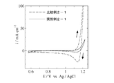
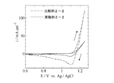
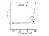
- Example 3 is a cyclic voltammogram obtained in Example 2-1 and Comparative Example 2-1. 3 is a cyclic voltammogram obtained in Example 2-2 and Comparative Example 2-2. It is a cyclic voltammogram obtained in Example 2-4.
- Example 1-1 A commercially available titanium plate (length 5 cm, width 1 cm, thickness 1 mm) was immersed in a 10% oxalic acid solution at 90 ° C. for 60 minutes for etching treatment, washed with water and dried.
- a butanol (nC 4 H 9 OH) solution containing 6 vol% concentrated hydrochloric acid has a molar ratio of chloroiridate hexahydrate (H 2 IrCl 6 ⁇ 6H 2 O) and tantalum chloride (TaCl 5 ) of 80:20.
- the coating solution was prepared so that the total of iridium and tantalum was 70 mg / mL in terms of metal.
- This coating solution was applied to the titanium plate, dried at 120 ° C. for 10 minutes, and then thermally decomposed in an electric furnace maintained at 360 ° C. for 20 minutes.
- the above application, drying and firing were repeated 5 times to produce an electrode having a catalyst layer formed on a titanium plate.
- As a result of structural analysis of this electrode by the X-ray diffraction method no diffraction peak corresponding to IrO 2 was observed in the X-ray diffraction image, and no diffraction peak corresponding to Ta 2 O 5 was observed. It was confirmed that the catalyst layer of the electrode was formed of amorphous iridium oxide and amorphous tantalum oxide.
- a catalyst layer of this electrode was covered with a polytetrafluoroethylene tape and the area was regulated to 1 cm 2 as an anode, a platinum plate as a cathode, and 0.1 mol / L of a 2 mol / L sulfuric acid aqueous solution.
- Constant current electrolysis was performed in a manganese sulfate solution in which manganese sulfate was dissolved at a current density of 10 mA / cm 2 , a temperature of 40 ° C., and an electrolysis time of 20 minutes.
- Example 1-2 An electrode was produced in the same manner as in Example 1-1 except that the pyrolysis temperature was changed from 360 ° C. to 380 ° C. As a result of structural analysis of the obtained electrode by the X-ray diffraction method, the diffraction line corresponding to IrO 2 became broad and weak peaks overlapped, and the diffraction peak corresponding to Ta 2 O 5 was not recognized. It was confirmed that the catalyst layer was formed of amorphous iridium oxide, crystalline iridium oxide, and amorphous tantalum oxide. Next, constant current electrolysis was performed by the method and conditions described in Example 1-1. From the change in weight before and after electrolysis, it was found that 2.3 mg / cm 2 of manganese compound was precipitated by electrolysis.
- Example 1-1 An electrode was produced in the same manner as in Example 1-1 except that the thermal decomposition temperature was changed from 360 ° C. to 470 ° C. As a result of structural analysis of the obtained electrode by the X-ray diffraction method, a sharp diffraction peak corresponding to IrO 2 was observed, but a diffraction peak corresponding to Ta 2 O 5 was not observed. It was confirmed to be formed from crystalline iridium oxide and amorphous tantalum oxide. Next, constant current electrolysis was performed by the method and conditions described in Example 1-1. After electrolysis, precipitates were clearly observed on the catalyst layer, and as a result of examining the change in the weight of the anode before and after electrolysis, it was found that 5 mg / cm 2 of manganese compound was deposited by electrolysis.
- Example 1-1 in which the iridium oxide in the catalyst layer is amorphous, the amount of manganese compound deposited is larger than that in Comparative Example 1-1 in which the amorphous iridium oxide is not included in the catalyst layer. It was found that 82% could be suppressed. Also, it was found that the precipitation amount of the manganese compound in Example 1-2 can be suppressed by 54% as compared with Comparative Example 1-1. On the other hand, from the measurement results of the electric double layer capacity in the sulfuric acid solution, the effective surface area of the electrodes of Example 1-1 and Example 1-2 increased compared to the electrode of Comparative Example 1-1.
- Example 1-1 the effective surface area of the electrode was 6 times or more that in Comparative Example 1-1, and it was also found that oxygen generation was greatly accelerated. Further, as a result of comparing the oxygen generation potential in the sulfuric acid solution, the oxygen generation potential at 50 mA / cm 2 was lower by about 0.2 V in Example 1-1 than in Comparative Example 1-1, and the oxygen generation potential was reduced. It became clear that it could be significantly reduced.
- Example 2-1 A commercially available titanium plate (length 5 cm, width 1 cm, thickness 1 mm) was immersed in a 10% oxalic acid solution at 90 ° C. for 60 minutes for etching treatment, washed with water and dried. A butanol (nC 4 H 9 OH) solution containing 6 vol% concentrated hydrochloric acid was mixed with 80:20 molar ratio of chloroiridate hexahydrate (H 2 IrCl 6 .6H 2 O) and tantalum pentachloride (TaCl 5 ) in a molar ratio.
- the coating solution was prepared so that the total of iridium and tantalum was 70 mg / mL in terms of metal.
- This coating solution was applied to the titanium plate, dried at 120 ° C. for 10 minutes, and then thermally decomposed in an electric furnace maintained at 360 ° C. for 20 minutes. The above application, drying and firing were repeated 5 times to produce an electrode having a catalyst layer formed on a titanium plate.
- As a result of structural analysis of this electrode by the X-ray diffraction method no diffraction peak corresponding to IrO 2 was observed in the X-ray diffraction image, and no diffraction peak corresponding to Ta 2 O 5 was observed.
- the catalyst layer of the electrode was formed of amorphous iridium oxide and amorphous tantalum oxide.
- the catalyst layer of this electrode is covered with a polytetrafluoroethylene tape and the area is regulated to 1 cm 2 , and 0.3 mol / L CoCl 2 is dissolved in distilled water using a platinum plate as a counter electrode.
- cyclic voltammograms were measured using a chloride electrolyte having a pH of 2.4 by adding hydrochloric acid under the conditions of a liquid temperature of 60 ° C. and a scanning speed of 5 mV / s.
- an Ag / AgCl electrode immersed in a KCl saturated solution was used as a reference electrode.
- Example 2-1 In the electrode manufacturing method in Example 2-1, an electrode was manufactured by the same method except that the thermal decomposition temperature was changed from 360 ° C. to 470 ° C. As a result of structural analysis of the obtained electrode by the X-ray diffraction method, a diffraction peak corresponding to IrO 2 was observed, but a diffraction peak corresponding to Ta 2 O 5 was not observed. Iridium oxide and amorphous tantalum oxide were confirmed. Next, cyclic voltammograms were measured under the conditions and methods described in Example 2-1.
- Example 2-1 The cyclic voltammograms obtained in Example 2-1 and Comparative Example 2-1 are shown in FIG. 1. From FIG. 1, a large oxidation current and a large reduction current with a peak were observed in Comparative Example 2-1, whereas in Example 2-1, the oxidation current was much smaller than that of Comparative Example 2-1, and No reduction current was seen.
- the oxidation current observed in Comparative Example 2-1 is the formation of cobalt oxyhydroxide, and the large reduction current with a peak is the reduction of cobalt oxyhydroxide attached on the electrode.
- an oxidation current was observed in Example 2-1, but no reduction current was observed, the oxidation reaction was not generation of cobalt oxyhydroxide but generation of oxygen and chlorine. That is, in Example 2-1, the production of cobalt oxyhydroxide was significantly suppressed as compared with Comparative Example 2-1.
- Example 2-2 A commercially available titanium plate (length 5 cm, width 1 cm, thickness 1 mm) was immersed in a 10% oxalic acid solution at 90 ° C. for 60 minutes for etching treatment, washed with water and dried. Next, butanol (nC 4 H 9 OH) and ruthenium chloride trihydrate (RuCl 3 .3H 2 O) and titanium-n-butoxide (Ti (C 4 H 9 O) 4 ) in a molar ratio of 30:70 The coating solution was prepared so that the total of ruthenium and titanium was 70 mg / mL in terms of metal. This coating solution was applied to the titanium plate, dried at 120 ° C.
- 0.9 mol / L CoCl 2 was dissolved in distilled water using the electrode layer coated with polytetrafluoroethylene tape and the area restricted to 1 cm 2 as the working electrode and the platinum plate as the counter electrode. Further, cyclic voltammograms were measured using a chloride electrolyte having a pH of 1.6 by adding hydrochloric acid under the conditions of a liquid temperature of 60 ° C. and a scanning speed of 25 mV / s. At this time, an Ag / AgCl electrode immersed in a KCl saturated solution was used as a reference electrode.
- Example 2-2 In the electrode manufacturing method in Example 2-2, an electrode was manufactured by the same method except that the thermal decomposition temperature was changed from 360 ° C. to 500 ° C. Results The obtained electrode was structurally analyzed by X-ray diffraction method, since the X-ray diffraction pattern RuO 2, and distinct diffraction peaks corresponding to RuO 2 and TiO 2 solid solution was observed, the catalyst of the electrode It was confirmed that the layer had crystalline ruthenium oxide but no amorphous ruthenium oxide. Next, cyclic voltammograms were measured under the conditions and methods described in Example 2-2.
- Example 2-2 Cyclic voltammograms obtained in Example 2-2 and Comparative Example 2-2 are shown in FIG. From FIG. 2, a large oxidation current and a large reduction current with a peak were observed in Comparative Example 2-2, whereas in Example 2-2, the oxidation current was smaller than that of Comparative Example 2-2 and the reduction current was Also decreased significantly.
- the oxidation current observed in Comparative Example 2-2 is the formation of cobalt oxyhydroxide, and the large reduction current with a peak is the reduction of cobalt oxyhydroxide deposited on the electrode.
- Example 2-2 both the oxidation current and the reduction current were smaller than those in Comparative Example 2-2.
- Example 2-2 the production of cobalt oxyhydroxide was significantly suppressed as compared with Comparative Example 2-2. It was done.
- Example 2-3 An electrode was produced in the same manner as in Example 2-2.
- the electrode catalyst layer was covered with a polytetrafluoroethylene tape and the area restricted to 1 cm 2 was used as the anode, the platinum plate as the cathode, 0.9 mol / L CoCl 2 was dissolved in distilled water, and hydrochloric acid was added.
- a chloride electrolyte having a pH of 1.6 and a liquid temperature of 60 ° C., a current density of 10 mA / cm 2 , and an electrolysis time of 40 minutes.
- the mass of the anode before electrolysis and after electrolysis was measured.
- Comparative Example 2-3 An electrode was produced in the same manner as in Comparative Example 2-2. Next, constant current electrolysis was performed under the conditions and methods described in Example 2-3, and the mass of the anode before and after electrolysis was measured.
- Example 2-3 and Comparative Example 2-3 precipitates were observed on the anode of Comparative Example 2-3 after electrolysis, and 6.9 mg / cm 2 of cobalt oxyhydroxide was precipitated from the mass change before and after electrolysis.
- the amount of cobalt oxyhydroxide deposited on the anode of Example 2-3 was 1.2 mg / cm 2 , which was greatly reduced to 17% of the deposited amount of Comparative Example 2-3.
- Example 2-4 An electrode was produced in the same manner as in the electrode production method in Example 2-1, except that the thermal decomposition temperature was changed from 360 ° C to 340 ° C. As a result of structural analysis of this electrode by the X-ray diffraction method, no diffraction peak corresponding to IrO 2 was observed in the X-ray diffraction image, and no diffraction peak corresponding to Ta 2 O 5 was observed. It was confirmed that the catalyst layer of the electrode was formed of amorphous iridium oxide and amorphous tantalum oxide.
- a catalyst layer of this electrode is covered with a polytetrafluoroethylene tape and the area is regulated to 1 cm 2 , and a platinum plate is used as a counter electrode, and 0.3 mol / L CoSO 4 .7H 2 O is added.
- a cyclic voltammogram was measured under conditions of a liquid temperature of 60 ° C. and a scanning speed of 5 mV / s by using a sulfuric acid electrolyte solution dissolved in distilled water and further added with sulfuric acid to a pH of 2.4. At this time, an Ag / AgCl electrode immersed in a KCl saturated solution was used as a reference electrode. From the cyclic voltammogram shown in FIG. 3, an oxidation current flows through this electrode, but no reduction current was observed. That is, the production of cobalt oxyhydroxide was completely suppressed.
- the present invention relates to the electrowinning of zinc in which high-purity zinc is collected by electrolysis using a solution obtained by extracting + 2-valent zinc ions from zinc ore, and + 2-valent zinc ions from zinc-containing materials recovered for recycling. It can be used for zinc electrowinning, such as recovering zinc metal by electrolysis using a solution in which is dissolved.
- the present invention provides an electrowinning of cobalt in which high purity cobalt is collected by electrolysis using a solution obtained by extracting +2 valent cobalt ions from cobalt ore, and a +2 valent from a cobalt-containing material recovered for recycling. It can be used for electrolytic extraction of cobalt, such as recovering cobalt metal by electrolysis using a solution in which cobalt ions are dissolved.
Landscapes
- Chemical & Material Sciences (AREA)
- Engineering & Computer Science (AREA)
- Chemical Kinetics & Catalysis (AREA)
- Electrochemistry (AREA)
- Materials Engineering (AREA)
- Metallurgy (AREA)
- Organic Chemistry (AREA)
- Electrolytic Production Of Metals (AREA)
- Electrolytic Production Of Non-Metals, Compounds, Apparatuses Therefor (AREA)
Abstract
Priority Applications (6)
| Application Number | Priority Date | Filing Date | Title |
|---|---|---|---|
| AU2009258626A AU2009258626A1 (en) | 2008-06-09 | 2009-06-09 | Anodes for electrolytic winning of zinc and cobalt and method for electrolytic winning |
| CN200980121621.2A CN102057081B (zh) | 2008-06-09 | 2009-06-09 | 一种阳极在锌及钴的电解提取中的应用、以及电解提取方法 |
| US12/997,127 US8357271B2 (en) | 2008-06-09 | 2009-06-09 | Anode for use in zinc and cobalt electrowinning and electrowinning method |
| ES09762474T ES2428006T3 (es) | 2008-06-09 | 2009-06-09 | Método para la obtención electrolítica de zinc |
| EP09762474.6A EP2287364B1 (fr) | 2008-06-09 | 2009-06-09 | Procédé d extraction par voie électrolytique de zinc |
| CA2755820A CA2755820C (fr) | 2008-06-09 | 2009-06-09 | Anode servant a l'extraction par voie electrolytique de zinc et de cobalt, et procede d'extraction par voie electrolytique |
Applications Claiming Priority (4)
| Application Number | Priority Date | Filing Date | Title |
|---|---|---|---|
| JP2008-151007 | 2008-06-09 | ||
| JP2008151007A JP4516617B2 (ja) | 2008-06-09 | 2008-06-09 | 亜鉛の電解採取用陽極および電解採取法 |
| JP2008163714A JP4516618B2 (ja) | 2008-06-23 | 2008-06-23 | コバルトの電解採取用陽極および電解採取法 |
| JP2008-163714 | 2008-06-23 |
Publications (1)
| Publication Number | Publication Date |
|---|---|
| WO2009151044A1 true WO2009151044A1 (fr) | 2009-12-17 |
Family
ID=41416751
Family Applications (1)
| Application Number | Title | Priority Date | Filing Date |
|---|---|---|---|
| PCT/JP2009/060504 WO2009151044A1 (fr) | 2008-06-09 | 2009-06-09 | Anode servant à l’extraction par voie électrolytique de zinc et de cobalt, et procédé d’extraction par voie électrolytique |
Country Status (7)
| Country | Link |
|---|---|
| US (1) | US8357271B2 (fr) |
| EP (2) | EP2287364B1 (fr) |
| CN (2) | CN102912385B (fr) |
| AU (1) | AU2009258626A1 (fr) |
| CA (1) | CA2755820C (fr) |
| ES (2) | ES2536832T3 (fr) |
| WO (1) | WO2009151044A1 (fr) |
Cited By (4)
| Publication number | Priority date | Publication date | Assignee | Title |
|---|---|---|---|---|
| WO2013038927A1 (fr) * | 2011-09-13 | 2013-03-21 | 学校法人同志社 | Electrode positive de génération de chlore |
| WO2013038928A1 (fr) * | 2011-09-13 | 2013-03-21 | 学校法人同志社 | Electrode positive pour un placage électrolytique et procédé de placage électrolytique utilisant l'électrode positive |
| CN103476970A (zh) * | 2011-03-25 | 2013-12-25 | 学校法人同志社 | 电解提取用阳极以及使用该阳极的电解提取法 |
| EP2535443A4 (fr) * | 2009-12-08 | 2015-05-20 | Doshisha | Système d'extraction électrolytique de métal, et procédé d'extraction électrolytique qui utilise le système |
Families Citing this family (8)
| Publication number | Priority date | Publication date | Assignee | Title |
|---|---|---|---|---|
| WO2013029186A1 (fr) | 2011-09-01 | 2013-03-07 | Trudel Simon | Matières électrocatalytiques et procédés de fabrication de celles-ci |
| ZA201207465B (en) * | 2011-10-09 | 2013-05-29 | Mintek | Direct electrowinning of cobalt |
| US9790605B2 (en) | 2013-06-27 | 2017-10-17 | Yale University | Iridium complexes for electrocatalysis |
| US10081650B2 (en) | 2013-07-03 | 2018-09-25 | Yale University | Metal oxide-organic hybrid materials for heterogeneous catalysis and methods of making and using thereof |
| EP3214206B1 (fr) * | 2016-03-04 | 2019-05-08 | Fritz Haber Institut der Max Planck Gesellschaft Department of Inorganic Chemistry | Oxohydroxydes ir pour l'oxydation électrochimique de l'eau et procédé pour la préparation de ceux-ci |
| KR102126183B1 (ko) * | 2017-11-29 | 2020-06-24 | 한국과학기술연구원 | 고분자 전해질 막 물 전기분해장치의 확산층 및 산소 전극 복합층 및 그 제조 방법, 이를 이용한 고분자 전해질 막 물 전기 분해 장치 |
| CN111139497B (zh) * | 2020-01-22 | 2022-11-29 | 同济大学 | 一种固体聚合物电解质电解槽用膜电极组件及制备方法 |
| CN113026056B (zh) * | 2021-03-08 | 2023-10-24 | 成都盛威兴科新材料研究院合伙企业(有限合伙) | 一种采用钴中间品二次电解生产电解钴的方法 |
Citations (4)
| Publication number | Priority date | Publication date | Assignee | Title |
|---|---|---|---|---|
| JPH07258897A (ja) * | 1994-03-22 | 1995-10-09 | Nippon Steel Corp | 不溶性電極及びその製造方法 |
| JP2004238697A (ja) * | 2003-02-07 | 2004-08-26 | Daiso Co Ltd | 酸素発生用電極 |
| JP2007146215A (ja) * | 2005-11-25 | 2007-06-14 | Daiso Co Ltd | 酸素発生用電極 |
| JP2007162050A (ja) | 2005-12-12 | 2007-06-28 | Permelec Electrode Ltd | 金属採取方法 |
Family Cites Families (7)
| Publication number | Priority date | Publication date | Assignee | Title |
|---|---|---|---|---|
| US3562008A (en) | 1968-10-14 | 1971-02-09 | Ppg Industries Inc | Method for producing a ruthenium coated titanium electrode |
| US4431196A (en) * | 1982-09-30 | 1984-02-14 | Mark R. Kutnyak | Lighting adapter kit and method for installing lights in a flying disc |
| DE3516523A1 (de) * | 1985-05-08 | 1986-11-13 | Sigri GmbH, 8901 Meitingen | Anode fuer elektrochemische prozesse |
| JPH07258697A (ja) | 1994-03-25 | 1995-10-09 | Medical Supeesu Kk | 粘土状石けんとその製造方法 |
| IT1302581B1 (it) * | 1998-10-01 | 2000-09-29 | Nora De | Anodo con migliorato rivestimento per la reazione di evoluzione diossigeno in elettroliti contenenti manganese. |
| US7393438B2 (en) * | 2004-07-22 | 2008-07-01 | Phelps Dodge Corporation | Apparatus for producing metal powder by electrowinning |
| US8022004B2 (en) * | 2008-05-24 | 2011-09-20 | Freeport-Mcmoran Corporation | Multi-coated electrode and method of making |
-
2009
- 2009-06-09 CA CA2755820A patent/CA2755820C/fr not_active Expired - Fee Related
- 2009-06-09 ES ES12175438.6T patent/ES2536832T3/es active Active
- 2009-06-09 WO PCT/JP2009/060504 patent/WO2009151044A1/fr active Application Filing
- 2009-06-09 CN CN201210391710.2A patent/CN102912385B/zh not_active Expired - Fee Related
- 2009-06-09 EP EP09762474.6A patent/EP2287364B1/fr not_active Not-in-force
- 2009-06-09 US US12/997,127 patent/US8357271B2/en active Active
- 2009-06-09 ES ES09762474T patent/ES2428006T3/es active Active
- 2009-06-09 CN CN200980121621.2A patent/CN102057081B/zh not_active Expired - Fee Related
- 2009-06-09 AU AU2009258626A patent/AU2009258626A1/en not_active Abandoned
- 2009-06-09 EP EP12175438.6A patent/EP2508651B1/fr not_active Not-in-force
Patent Citations (5)
| Publication number | Priority date | Publication date | Assignee | Title |
|---|---|---|---|---|
| JPH07258897A (ja) * | 1994-03-22 | 1995-10-09 | Nippon Steel Corp | 不溶性電極及びその製造方法 |
| JP2004238697A (ja) * | 2003-02-07 | 2004-08-26 | Daiso Co Ltd | 酸素発生用電極 |
| JP3914162B2 (ja) | 2003-02-07 | 2007-05-16 | ダイソー株式会社 | 酸素発生用電極 |
| JP2007146215A (ja) * | 2005-11-25 | 2007-06-14 | Daiso Co Ltd | 酸素発生用電極 |
| JP2007162050A (ja) | 2005-12-12 | 2007-06-28 | Permelec Electrode Ltd | 金属採取方法 |
Non-Patent Citations (3)
| Title |
|---|
| S. NIJJER; J. THONSTAD; G. M. HAARBERG, ELECTROCHIMICA ACTA, vol. 46, no. 23, 2001, pages 3503 - 3508 |
| See also references of EP2287364A4 |
| T. AKRE; G. M. HAARBERG; S. HAARBERG; J. THONSTAD; O. M. DOTTERUD, ECS PROCEEDINGS, PV 2004-18, 2005, pages 276 - 287 |
Cited By (7)
| Publication number | Priority date | Publication date | Assignee | Title |
|---|---|---|---|---|
| EP2535443A4 (fr) * | 2009-12-08 | 2015-05-20 | Doshisha | Système d'extraction électrolytique de métal, et procédé d'extraction électrolytique qui utilise le système |
| EP3088569A1 (fr) * | 2009-12-08 | 2016-11-02 | The Doshisha | Procédé d'extraction électrolytique de nickel |
| CN103476970A (zh) * | 2011-03-25 | 2013-12-25 | 学校法人同志社 | 电解提取用阳极以及使用该阳极的电解提取法 |
| WO2013038927A1 (fr) * | 2011-09-13 | 2013-03-21 | 学校法人同志社 | Electrode positive de génération de chlore |
| WO2013038928A1 (fr) * | 2011-09-13 | 2013-03-21 | 学校法人同志社 | Electrode positive pour un placage électrolytique et procédé de placage électrolytique utilisant l'électrode positive |
| RU2561565C1 (ru) * | 2011-09-13 | 2015-08-27 | Дзе Досиса | Анод для выделения хлора |
| US9556534B2 (en) | 2011-09-13 | 2017-01-31 | The Doshisha | Anode for electroplating and method for electroplating using anode |
Also Published As
| Publication number | Publication date |
|---|---|
| CA2755820A1 (fr) | 2009-12-17 |
| EP2287364A4 (fr) | 2011-07-06 |
| US20110079518A1 (en) | 2011-04-07 |
| EP2508651A1 (fr) | 2012-10-10 |
| CN102912385A (zh) | 2013-02-06 |
| CA2755820C (fr) | 2014-02-04 |
| CN102912385B (zh) | 2015-06-10 |
| CN102057081A (zh) | 2011-05-11 |
| ES2536832T3 (es) | 2015-05-29 |
| CN102057081B (zh) | 2013-04-03 |
| US8357271B2 (en) | 2013-01-22 |
| AU2009258626A1 (en) | 2009-12-17 |
| EP2508651B1 (fr) | 2015-02-25 |
| ES2428006T3 (es) | 2013-11-05 |
| EP2287364A1 (fr) | 2011-02-23 |
| EP2287364B1 (fr) | 2013-07-10 |
Similar Documents
| Publication | Publication Date | Title |
|---|---|---|
| WO2009151044A1 (fr) | Anode servant à l’extraction par voie électrolytique de zinc et de cobalt, et procédé d’extraction par voie électrolytique | |
| JP4916040B1 (ja) | 電解採取用陽極および該陽極を用いた電解採取法 | |
| JP4516618B2 (ja) | コバルトの電解採取用陽極および電解採取法 | |
| JP5008043B1 (ja) | 塩素発生用陽極 | |
| JP5013438B2 (ja) | 金属の電解採取用陽極および電解採取方法 | |
| JP4516617B2 (ja) | 亜鉛の電解採取用陽極および電解採取法 | |
| JP2011122183A5 (fr) | ||
| US20170218531A1 (en) | Metal electrowinning anode and electrowinning method | |
| AU2013203723A1 (en) | Anode for Use in Zinc and Cobalt Electrowinning and Electrowinning Method | |
| JP2019081919A (ja) | 電解法 |
Legal Events
| Date | Code | Title | Description |
|---|---|---|---|
| WWE | Wipo information: entry into national phase |
Ref document number: 200980121621.2 Country of ref document: CN |
|
| 121 | Ep: the epo has been informed by wipo that ep was designated in this application |
Ref document number: 09762474 Country of ref document: EP Kind code of ref document: A1 |
|
| WWE | Wipo information: entry into national phase |
Ref document number: 2009258626 Country of ref document: AU Ref document number: 2009762474 Country of ref document: EP |
|
| WWE | Wipo information: entry into national phase |
Ref document number: 12997127 Country of ref document: US |
|
| NENP | Non-entry into the national phase |
Ref country code: DE |
|
| ENP | Entry into the national phase |
Ref document number: 2009258626 Country of ref document: AU Date of ref document: 20090609 Kind code of ref document: A |
|
| WWE | Wipo information: entry into national phase |
Ref document number: 2755820 Country of ref document: CA |