WO2009139256A1 - 排気ガス浄化システム及びその制御方法 - Google Patents
排気ガス浄化システム及びその制御方法 Download PDFInfo
- Publication number
- WO2009139256A1 WO2009139256A1 PCT/JP2009/057560 JP2009057560W WO2009139256A1 WO 2009139256 A1 WO2009139256 A1 WO 2009139256A1 JP 2009057560 W JP2009057560 W JP 2009057560W WO 2009139256 A1 WO2009139256 A1 WO 2009139256A1
- Authority
- WO
- WIPO (PCT)
- Prior art keywords
- temperature
- catalyst
- exhaust gas
- nox
- oxidation catalyst
- Prior art date
Links
Images


Classifications
-
- F—MECHANICAL ENGINEERING; LIGHTING; HEATING; WEAPONS; BLASTING
- F01—MACHINES OR ENGINES IN GENERAL; ENGINE PLANTS IN GENERAL; STEAM ENGINES
- F01N—GAS-FLOW SILENCERS OR EXHAUST APPARATUS FOR MACHINES OR ENGINES IN GENERAL; GAS-FLOW SILENCERS OR EXHAUST APPARATUS FOR INTERNAL COMBUSTION ENGINES
- F01N3/00—Exhaust or silencing apparatus having means for purifying, rendering innocuous, or otherwise treating exhaust
- F01N3/02—Exhaust or silencing apparatus having means for purifying, rendering innocuous, or otherwise treating exhaust for cooling, or for removing solid constituents of, exhaust
- F01N3/021—Exhaust or silencing apparatus having means for purifying, rendering innocuous, or otherwise treating exhaust for cooling, or for removing solid constituents of, exhaust by means of filters
- F01N3/023—Exhaust or silencing apparatus having means for purifying, rendering innocuous, or otherwise treating exhaust for cooling, or for removing solid constituents of, exhaust by means of filters using means for regenerating the filters, e.g. by burning trapped particles
- F01N3/025—Exhaust or silencing apparatus having means for purifying, rendering innocuous, or otherwise treating exhaust for cooling, or for removing solid constituents of, exhaust by means of filters using means for regenerating the filters, e.g. by burning trapped particles using fuel burner or by adding fuel to exhaust
- F01N3/0253—Exhaust or silencing apparatus having means for purifying, rendering innocuous, or otherwise treating exhaust for cooling, or for removing solid constituents of, exhaust by means of filters using means for regenerating the filters, e.g. by burning trapped particles using fuel burner or by adding fuel to exhaust adding fuel to exhaust gases
-
- F—MECHANICAL ENGINEERING; LIGHTING; HEATING; WEAPONS; BLASTING
- F01—MACHINES OR ENGINES IN GENERAL; ENGINE PLANTS IN GENERAL; STEAM ENGINES
- F01N—GAS-FLOW SILENCERS OR EXHAUST APPARATUS FOR MACHINES OR ENGINES IN GENERAL; GAS-FLOW SILENCERS OR EXHAUST APPARATUS FOR INTERNAL COMBUSTION ENGINES
- F01N13/00—Exhaust or silencing apparatus characterised by constructional features ; Exhaust or silencing apparatus, or parts thereof, having pertinent characteristics not provided for in, or of interest apart from, groups F01N1/00 - F01N5/00, F01N9/00, F01N11/00
- F01N13/009—Exhaust or silencing apparatus characterised by constructional features ; Exhaust or silencing apparatus, or parts thereof, having pertinent characteristics not provided for in, or of interest apart from, groups F01N1/00 - F01N5/00, F01N9/00, F01N11/00 having two or more separate purifying devices arranged in series
-
- F—MECHANICAL ENGINEERING; LIGHTING; HEATING; WEAPONS; BLASTING
- F01—MACHINES OR ENGINES IN GENERAL; ENGINE PLANTS IN GENERAL; STEAM ENGINES
- F01N—GAS-FLOW SILENCERS OR EXHAUST APPARATUS FOR MACHINES OR ENGINES IN GENERAL; GAS-FLOW SILENCERS OR EXHAUST APPARATUS FOR INTERNAL COMBUSTION ENGINES
- F01N3/00—Exhaust or silencing apparatus having means for purifying, rendering innocuous, or otherwise treating exhaust
- F01N3/02—Exhaust or silencing apparatus having means for purifying, rendering innocuous, or otherwise treating exhaust for cooling, or for removing solid constituents of, exhaust
- F01N3/021—Exhaust or silencing apparatus having means for purifying, rendering innocuous, or otherwise treating exhaust for cooling, or for removing solid constituents of, exhaust by means of filters
-
- F—MECHANICAL ENGINEERING; LIGHTING; HEATING; WEAPONS; BLASTING
- F01—MACHINES OR ENGINES IN GENERAL; ENGINE PLANTS IN GENERAL; STEAM ENGINES
- F01N—GAS-FLOW SILENCERS OR EXHAUST APPARATUS FOR MACHINES OR ENGINES IN GENERAL; GAS-FLOW SILENCERS OR EXHAUST APPARATUS FOR INTERNAL COMBUSTION ENGINES
- F01N3/00—Exhaust or silencing apparatus having means for purifying, rendering innocuous, or otherwise treating exhaust
- F01N3/08—Exhaust or silencing apparatus having means for purifying, rendering innocuous, or otherwise treating exhaust for rendering innocuous
- F01N3/0807—Exhaust or silencing apparatus having means for purifying, rendering innocuous, or otherwise treating exhaust for rendering innocuous by using absorbents or adsorbents
- F01N3/0828—Exhaust or silencing apparatus having means for purifying, rendering innocuous, or otherwise treating exhaust for rendering innocuous by using absorbents or adsorbents characterised by the absorbed or adsorbed substances
- F01N3/0842—Nitrogen oxides
-
- F—MECHANICAL ENGINEERING; LIGHTING; HEATING; WEAPONS; BLASTING
- F01—MACHINES OR ENGINES IN GENERAL; ENGINE PLANTS IN GENERAL; STEAM ENGINES
- F01N—GAS-FLOW SILENCERS OR EXHAUST APPARATUS FOR MACHINES OR ENGINES IN GENERAL; GAS-FLOW SILENCERS OR EXHAUST APPARATUS FOR INTERNAL COMBUSTION ENGINES
- F01N3/00—Exhaust or silencing apparatus having means for purifying, rendering innocuous, or otherwise treating exhaust
- F01N3/08—Exhaust or silencing apparatus having means for purifying, rendering innocuous, or otherwise treating exhaust for rendering innocuous
- F01N3/10—Exhaust or silencing apparatus having means for purifying, rendering innocuous, or otherwise treating exhaust for rendering innocuous by thermal or catalytic conversion of noxious components of exhaust
- F01N3/103—Oxidation catalysts for HC and CO only
-
- F—MECHANICAL ENGINEERING; LIGHTING; HEATING; WEAPONS; BLASTING
- F01—MACHINES OR ENGINES IN GENERAL; ENGINE PLANTS IN GENERAL; STEAM ENGINES
- F01N—GAS-FLOW SILENCERS OR EXHAUST APPARATUS FOR MACHINES OR ENGINES IN GENERAL; GAS-FLOW SILENCERS OR EXHAUST APPARATUS FOR INTERNAL COMBUSTION ENGINES
- F01N3/00—Exhaust or silencing apparatus having means for purifying, rendering innocuous, or otherwise treating exhaust
- F01N3/08—Exhaust or silencing apparatus having means for purifying, rendering innocuous, or otherwise treating exhaust for rendering innocuous
- F01N3/10—Exhaust or silencing apparatus having means for purifying, rendering innocuous, or otherwise treating exhaust for rendering innocuous by thermal or catalytic conversion of noxious components of exhaust
- F01N3/105—General auxiliary catalysts, e.g. upstream or downstream of the main catalyst
- F01N3/106—Auxiliary oxidation catalysts
-
- F—MECHANICAL ENGINEERING; LIGHTING; HEATING; WEAPONS; BLASTING
- F01—MACHINES OR ENGINES IN GENERAL; ENGINE PLANTS IN GENERAL; STEAM ENGINES
- F01N—GAS-FLOW SILENCERS OR EXHAUST APPARATUS FOR MACHINES OR ENGINES IN GENERAL; GAS-FLOW SILENCERS OR EXHAUST APPARATUS FOR INTERNAL COMBUSTION ENGINES
- F01N3/00—Exhaust or silencing apparatus having means for purifying, rendering innocuous, or otherwise treating exhaust
- F01N3/08—Exhaust or silencing apparatus having means for purifying, rendering innocuous, or otherwise treating exhaust for rendering innocuous
- F01N3/10—Exhaust or silencing apparatus having means for purifying, rendering innocuous, or otherwise treating exhaust for rendering innocuous by thermal or catalytic conversion of noxious components of exhaust
- F01N3/18—Exhaust or silencing apparatus having means for purifying, rendering innocuous, or otherwise treating exhaust for rendering innocuous by thermal or catalytic conversion of noxious components of exhaust characterised by methods of operation; Control
- F01N3/20—Exhaust or silencing apparatus having means for purifying, rendering innocuous, or otherwise treating exhaust for rendering innocuous by thermal or catalytic conversion of noxious components of exhaust characterised by methods of operation; Control specially adapted for catalytic conversion ; Methods of operation or control of catalytic converters
- F01N3/2006—Periodically heating or cooling catalytic reactors, e.g. at cold starting or overheating
- F01N3/2033—Periodically heating or cooling catalytic reactors, e.g. at cold starting or overheating using a fuel burner or introducing fuel into exhaust duct
-
- F—MECHANICAL ENGINEERING; LIGHTING; HEATING; WEAPONS; BLASTING
- F01—MACHINES OR ENGINES IN GENERAL; ENGINE PLANTS IN GENERAL; STEAM ENGINES
- F01N—GAS-FLOW SILENCERS OR EXHAUST APPARATUS FOR MACHINES OR ENGINES IN GENERAL; GAS-FLOW SILENCERS OR EXHAUST APPARATUS FOR INTERNAL COMBUSTION ENGINES
- F01N3/00—Exhaust or silencing apparatus having means for purifying, rendering innocuous, or otherwise treating exhaust
- F01N3/08—Exhaust or silencing apparatus having means for purifying, rendering innocuous, or otherwise treating exhaust for rendering innocuous
- F01N3/10—Exhaust or silencing apparatus having means for purifying, rendering innocuous, or otherwise treating exhaust for rendering innocuous by thermal or catalytic conversion of noxious components of exhaust
- F01N3/24—Exhaust or silencing apparatus having means for purifying, rendering innocuous, or otherwise treating exhaust for rendering innocuous by thermal or catalytic conversion of noxious components of exhaust characterised by constructional aspects of converting apparatus
- F01N3/28—Construction of catalytic reactors
- F01N3/2803—Construction of catalytic reactors characterised by structure, by material or by manufacturing of catalyst support
- F01N3/2807—Metal other than sintered metal
- F01N3/281—Metallic honeycomb monoliths made of stacked or rolled sheets, foils or plates
- F01N3/2821—Metallic honeycomb monoliths made of stacked or rolled sheets, foils or plates the support being provided with means to enhance the mixing process inside the converter, e.g. sheets, plates or foils with protrusions or projections to create turbulence
-
- F—MECHANICAL ENGINEERING; LIGHTING; HEATING; WEAPONS; BLASTING
- F01—MACHINES OR ENGINES IN GENERAL; ENGINE PLANTS IN GENERAL; STEAM ENGINES
- F01N—GAS-FLOW SILENCERS OR EXHAUST APPARATUS FOR MACHINES OR ENGINES IN GENERAL; GAS-FLOW SILENCERS OR EXHAUST APPARATUS FOR INTERNAL COMBUSTION ENGINES
- F01N2250/00—Combinations of different methods of purification
- F01N2250/02—Combinations of different methods of purification filtering and catalytic conversion
-
- F—MECHANICAL ENGINEERING; LIGHTING; HEATING; WEAPONS; BLASTING
- F01—MACHINES OR ENGINES IN GENERAL; ENGINE PLANTS IN GENERAL; STEAM ENGINES
- F01N—GAS-FLOW SILENCERS OR EXHAUST APPARATUS FOR MACHINES OR ENGINES IN GENERAL; GAS-FLOW SILENCERS OR EXHAUST APPARATUS FOR INTERNAL COMBUSTION ENGINES
- F01N2330/00—Structure of catalyst support or particle filter
- F01N2330/02—Metallic plates or honeycombs, e.g. superposed or rolled-up corrugated or otherwise deformed sheet metal
-
- F—MECHANICAL ENGINEERING; LIGHTING; HEATING; WEAPONS; BLASTING
- F01—MACHINES OR ENGINES IN GENERAL; ENGINE PLANTS IN GENERAL; STEAM ENGINES
- F01N—GAS-FLOW SILENCERS OR EXHAUST APPARATUS FOR MACHINES OR ENGINES IN GENERAL; GAS-FLOW SILENCERS OR EXHAUST APPARATUS FOR INTERNAL COMBUSTION ENGINES
- F01N2330/00—Structure of catalyst support or particle filter
- F01N2330/30—Honeycomb supports characterised by their structural details
- F01N2330/38—Honeycomb supports characterised by their structural details flow channels with means to enhance flow mixing,(e.g. protrusions or projections)
-
- F—MECHANICAL ENGINEERING; LIGHTING; HEATING; WEAPONS; BLASTING
- F01—MACHINES OR ENGINES IN GENERAL; ENGINE PLANTS IN GENERAL; STEAM ENGINES
- F01N—GAS-FLOW SILENCERS OR EXHAUST APPARATUS FOR MACHINES OR ENGINES IN GENERAL; GAS-FLOW SILENCERS OR EXHAUST APPARATUS FOR INTERNAL COMBUSTION ENGINES
- F01N2560/00—Exhaust systems with means for detecting or measuring exhaust gas components or characteristics
- F01N2560/06—Exhaust systems with means for detecting or measuring exhaust gas components or characteristics the means being a temperature sensor
-
- F—MECHANICAL ENGINEERING; LIGHTING; HEATING; WEAPONS; BLASTING
- F01—MACHINES OR ENGINES IN GENERAL; ENGINE PLANTS IN GENERAL; STEAM ENGINES
- F01N—GAS-FLOW SILENCERS OR EXHAUST APPARATUS FOR MACHINES OR ENGINES IN GENERAL; GAS-FLOW SILENCERS OR EXHAUST APPARATUS FOR INTERNAL COMBUSTION ENGINES
- F01N2610/00—Adding substances to exhaust gases
- F01N2610/03—Adding substances to exhaust gases the substance being hydrocarbons, e.g. engine fuel
-
- F—MECHANICAL ENGINEERING; LIGHTING; HEATING; WEAPONS; BLASTING
- F01—MACHINES OR ENGINES IN GENERAL; ENGINE PLANTS IN GENERAL; STEAM ENGINES
- F01N—GAS-FLOW SILENCERS OR EXHAUST APPARATUS FOR MACHINES OR ENGINES IN GENERAL; GAS-FLOW SILENCERS OR EXHAUST APPARATUS FOR INTERNAL COMBUSTION ENGINES
- F01N2900/00—Details of electrical control or of the monitoring of the exhaust gas treating apparatus
- F01N2900/06—Parameters used for exhaust control or diagnosing
- F01N2900/16—Parameters used for exhaust control or diagnosing said parameters being related to the exhaust apparatus, e.g. particulate filter or catalyst
- F01N2900/1602—Temperature of exhaust gas apparatus
-
- Y—GENERAL TAGGING OF NEW TECHNOLOGICAL DEVELOPMENTS; GENERAL TAGGING OF CROSS-SECTIONAL TECHNOLOGIES SPANNING OVER SEVERAL SECTIONS OF THE IPC; TECHNICAL SUBJECTS COVERED BY FORMER USPC CROSS-REFERENCE ART COLLECTIONS [XRACs] AND DIGESTS
- Y02—TECHNOLOGIES OR APPLICATIONS FOR MITIGATION OR ADAPTATION AGAINST CLIMATE CHANGE
- Y02T—CLIMATE CHANGE MITIGATION TECHNOLOGIES RELATED TO TRANSPORTATION
- Y02T10/00—Road transport of goods or passengers
- Y02T10/10—Internal combustion engine [ICE] based vehicles
- Y02T10/12—Improving ICE efficiencies
Definitions
- the present invention relates to an exhaust gas purification system having at least one of a NOx occlusion reduction catalyst or a DPF with catalyst, and NOx regeneration control for restoring the NOx occlusion ability of the NOx occlusion reduction catalyst and recovery of the PM trapping capacity of the DPF with catalyst.
- the present invention relates to an exhaust gas purification system and a control method for the exhaust gas purification system that can perform the forced PM regeneration control even when the operating state of the internal combustion engine is in a low load state.
- LNT lean NOx trap
- DeNOx catalyst NOx purification catalysts
- GDI direct gasoline injection engines
- This catalyst is formed by supporting an occlusion material of an alkali metal (for example, potassium K) or an alkaline earth metal (for example, barium Ba) together with a noble metal such as platinum Pt.
- This NOx occlusion reduction type catalyst oxidizes NO in the exhaust gas and occludes NOx in the form of nitrate in the occlusion material when the exhaust gas is in an oxygen-rich air-fuel ratio lean state.
- the catalyst releases the stored NOx and reduces the released NOx with a reducing agent such as HC and CO by a three-way catalyst function. Due to these functions, the catalyst reduces NOx.
- a reducing agent such as fuel is supplied to the NOx occlusion reduction catalyst.
- the supply of the reducing agent is performed by performing post-injection in which fuel is further injected after main injection in in-cylinder fuel injection control, or direct injection in the exhaust pipe in which fuel is directly injected into the exhaust pipe.
- a continuous regeneration type diesel particulate filter device that collects PM (particulate matter) discharged from a diesel engine with a filter.
- PM particulate matter
- this continuous regeneration DPF device when the exhaust gas temperature is relatively high (about 350 ° C. or higher), PM collected by the filter is continuously burned and purified.
- the exhaust gas temperature is low, the temperature of the oxidation catalyst or PM oxidation catalyst carried by the filter is lowered and is not activated, so it is difficult to oxidize PM and self-regenerate the filter. Therefore, clogging progresses due to the accumulation of PM on the filter, causing a problem of increased exhaust pressure.
- forced PM regeneration is performed.
- the exhaust gas is forcibly raised in temperature and the collected PM is forcibly burned and removed.
- post-injection or direct injection into the exhaust pipe is performed to supply unburned HC (hydrocarbon) such as fuel into the exhaust gas, and the supplied unburned HC is disposed upstream of the filter. It is burned with an oxidation catalyst or an oxidation catalyst carried on a filter. The oxidation reaction heat is used to raise the exhaust gas temperature at the filter inlet and the filter surface. As a result, the temperature of the filter is raised above the temperature at which the PM accumulated in the filter burns, and the PM is burned and removed.
- the direct injection in the exhaust pipe has an advantage that the supply amount of unburned HC can be adjusted without affecting the combustion in the cylinder. Therefore, the direct injection in the exhaust pipe that directly injects fuel into the exhaust pipe is the NOx occlusion reduction type. It has begun to be put to practical use for reducing agent injection in a catalyst and exhaust gas temperature raising for forcibly burning PM collected in a DPF.
- the oxidation reaction does not occur even if the fuel is injected into the exhaust pipe below the activation temperature of the NOx storage reduction catalyst or the oxidation catalyst. It flows out through these catalysts and generates white smoke.
- unburned HC is not gasified as in the case of post injection, and therefore white smoke is more likely to be generated than in the case of post injection. Therefore, the area where direct injection in the exhaust pipe can be used is regulated by the activation temperature of the catalyst, so it is difficult to perform NOx regeneration of the NOx storage reduction catalyst or forced regeneration of the DPF during low-load driving or the like. There's a problem.
- This cell structure has a cell structure portion including an outer wall on the outer peripheral surface and a partition wall forming a plurality of cells communicating from one end to the other end.
- the cell structure is made mainly of a ceramic material or a metal material, and the outer wall is made mainly of a ceramic material, so that the heat insulation of the outer wall is made high. Thereby, the temperature increase rate of the cell structure is improved, and the temperature distribution is made uniform.
- the present invention has been made in view of the above situation, and an object of the present invention is to provide a carrier with a metal material or a specific heat of the metal material in an exhaust gas purification system using at least one of a NOx purification catalyst and a DPF with catalyst.
- a NOx purification catalyst that has the following specific heat and that has an exhaust gas mixing function
- NOx regeneration of NOx occlusion reduction type catalyst and PM forced regeneration of DPF with catalyst are performed in the operating state of the internal combustion engine.
- An object of the present invention is to provide an exhaust gas purification system that can be implemented even in a low-load operation state and a control method thereof.
- An exhaust gas purification system for achieving the above object includes an exhaust pipe direct injection device, an oxidation catalyst, and at least one of a NOx purification catalyst or a DPF with catalyst from the upstream side of the exhaust passage of the internal combustion engine.
- the oxidation catalyst carrier is formed of a metal material or a material having a specific heat equal to or lower than the specific heat of the metal material and has a structure having a function of mixing the exhaust gas.
- the oxidation catalyst has a function of mixing exhaust gas, that is, a mixer function, so that the unburned fuel and the exhaust gas are substantially uniform while passing through the support of the oxidation catalyst. To mix.
- the support for the oxidation catalyst is formed of a metal material or a material having a specific heat equal to or lower than that of the metal material, the specific heat of the entire oxidation catalyst is reduced. Therefore, the amount of heat required for temperature increase is reduced, and the temperature of the oxidation catalyst increases rapidly. Further, since the metal material has a high thermal conductivity, the oxidation catalyst tends to have a uniform temperature as a whole. Therefore, the temperature of the oxidation catalyst can be raised relatively quickly at the start of operation of the internal combustion engine, and can be quickly raised even with a small amount of oxidation reaction heat of the unburned fuel.
- the exhaust temperature rises and falls in the slow acceleration state.
- the temperature change width of the oxidation catalyst that follows it is small, the oxidation catalyst does not reach the catalyst activation temperature (for example, 200 ° C.) unless it is in a certain acceleration state.
- the oxidation catalyst A formed of a carrier of a material having a relatively small specific heat such as a metal material as in the present invention the temperature change of the oxidation catalyst that follows the rise and fall of the exhaust temperature in the slow acceleration state is reduced. Since the width is large, the oxidation catalyst easily reaches the catalyst activation temperature even for a short time.
- the temperature of the oxidation catalyst can be raised and maintained above the catalyst activation temperature. As a result, even if the operation state of the internal combustion engine is a low load operation state, the exhaust gas, the NOx occlusion reduction type catalyst, and the DPF with catalyst can be heated.
- the exhaust gas purification system when the first index temperature indicating the temperature of the oxidation catalyst exceeds the first determination temperature, the exhaust gas purification system is directly connected to the exhaust pipe at a predetermined first supply amount for raising the temperature of the oxidation catalyst.
- the second determination temperature when the second determination temperature is exceeded, direct injection into the exhaust pipe is performed at a predetermined second supply amount for raising the temperature of the exhaust gas, and the temperature of the NOx occlusion reduction type catalyst or the DPF with catalyst is indicated.
- an exhaust gas purification control device that performs direct injection in the exhaust pipe with a predetermined third supply amount that performs NOx regeneration or PM forced regeneration is configured.
- the first index temperature indicating the temperature of the oxidation catalyst exceeds the first determination temperature
- direct injection in the exhaust pipe is performed with a relatively small predetermined first supply amount, and oxidation is performed.
- the temperature of the oxidation catalyst can be increased by the oxidation reaction of the unburned fuel in the catalyst.
- the first index temperature rises and exceeds the second determination temperature
- it is assumed that the temperature of the oxidation catalyst can be stably maintained at the activation temperature or higher, and the predetermined first amount of the oxidation catalyst can be oxidized. Inject directly into the exhaust pipe with 2 supply amounts.
- the temperature of the exhaust gas can be raised by the heat generated by the oxidation reaction of the unburned fuel directly injected into the exhaust pipe in the oxidation catalyst. Note that the second determination temperature is higher by about 10 ° C. to 30 ° C. than the first determination temperature.
- This predetermined first supply amount is for raising the temperature of the oxidation catalyst itself so that the temperature of the oxidation catalyst can be continuously maintained at the activation temperature or higher. This is performed for a relatively short time until the determination temperature is reached.
- the predetermined second supply amount increases the exhaust gas in order to raise the temperature of the downstream NOx storage reduction catalyst and the DPF with catalyst while the oxidation catalyst is continuously maintained at the activation temperature or higher.
- the unburned fuel is supplied at a predetermined second supply amount different from the first supply amount.
- the second supply amount is set to an amount sufficient to raise the temperature of the exhaust gas, the NOx storage reduction catalyst, the DPF with catalyst, and the like. That is, the second supply amount is also obtained in the same manner as the first supply amount according to the characteristic curve shown in FIG.
- NOx regeneration can be performed by direct injection in the exhaust pipe with the third supply amount.
- a predetermined third supply PM forced regeneration can be performed by directly injecting into the exhaust pipe in an amount.
- the exhaust gas purification control device employs a temperature at which the temperature of the oxidation catalyst becomes 200 ° C. as the first determination temperature, and the oxidation catalyst as the second determination temperature.
- the temperature at which the temperature becomes 220 ° C. is adopted, and the temperature at which the oxidation catalyst temperature becomes 250 ° C. is adopted as the third judgment temperature for NOx regeneration, or the third judgment temperature for PM forced regeneration.
- the temperature at which the temperature of the oxidation catalyst is 300 ° C. is adopted.
- each determination temperature can be set to an appropriate value, so that the temperature increase of the oxidation catalyst, the temperature increase of the exhaust gas, and NOx regeneration or PM forced regeneration can be efficiently performed.
- the exhaust gas purification system control method for achieving the above-described object is characterized in that at least one of the direct injection device in the exhaust pipe, the oxidation catalyst, the NOx purification catalyst, or the DPF with catalyst from the upstream side of the exhaust passage of the internal combustion engine.
- a control method for an exhaust gas purification system in which the support for the oxidation catalyst is made of a metal material or a material having a specific heat equal to or lower than the specific heat of the metal material and has a structure having an exhaust gas mixing function.
- the exhaust gas is directly injected into the exhaust pipe at a predetermined second supply amount for raising the temperature of the exhaust gas, and the second index temperature indicating the temperature of the NOx storage reduction catalyst or the DPF with catalyst is set to the third determination temperature.
- the exhaust pipe direct injection in a predetermined third supply amount for performing NOx regeneration or PM forced regeneration.
- the first index temperature indicating the temperature of the oxidation catalyst exceeds the first determination temperature
- direct oxidation in the exhaust pipe is performed with a relatively small predetermined first supply amount and oxidation is performed.
- the temperature of the catalyst can be raised.
- the exhaust pipe is filled with a predetermined second supply amount that can be oxidized by the oxidation catalyst.
- NOx regeneration can be performed by direct injection in the exhaust pipe with the third supply amount.
- a predetermined third supply PM forced regeneration can be performed by directly injecting into the exhaust pipe in an amount.
- each determination temperature can be set to an appropriate value, so that the temperature increase of the oxidation catalyst, the temperature increase of the exhaust gas, and NOx regeneration or PM forced regeneration can be performed efficiently.
- the oxidation catalyst is formed of a ceramic carrier, In the conventional technology for supplying fuel, it is possible to perform these regenerations even in the case of low-load traveling operation in which NOx regeneration or PM forced regeneration cannot be performed, and NOx regeneration or PM forced regeneration in a wider traveling region. Can be implemented.
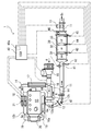
- FIG. 1 is a diagram schematically showing the configuration of an exhaust gas purification system according to an embodiment of the present invention.
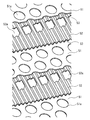
- FIG. 2 is a diagram schematically showing a PE structure in which a perforated flat foil and a perforated wave foil are laminated.
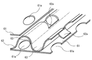
- FIG. 3 is a diagram schematically showing an LS structure in which a perforated flat foil and a wave foil provided with a notch are stacked.
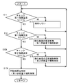
- FIG. 4 is a diagram showing an example of a control flow related to NOx regeneration in the control method for the exhaust gas purification system according to the embodiment of the present invention.
- FIG. 5 is a diagram showing an example of a control flow related to PM forced regeneration in the control method of the exhaust gas purification system according to the embodiment of the present invention.
- FIG. 6 is a diagram comparing the exhaust gas temperature at the outlet of the oxidation catalyst during traveling in the oxidation catalyst of the metal material carrier of the example and the oxidation catalyst of the cordierite carrier of the conventional example.
- FIG. 7 is a diagram schematically showing the relationship between the temperature of the oxidation catalyst and HC light off.
- FIG. 1 shows a configuration of an exhaust gas purification system 1 according to an embodiment of the present invention.
- a turbine 12 a of the turbocharger 12, an exhaust gas purification device 30, and an exhaust throttle valve 13 are provided in an exhaust passage 11 of a diesel engine (internal combustion engine) 10 from the upstream side.
- the exhaust gas treatment device 30 is configured by providing, in order from the upstream side, an oxidation catalyst (DOC) 31, a NOx occlusion reduction catalyst (LNT) 32, a catalyst-attached DPF (CSF) 33 carrying an oxidation catalyst or a PM oxidation catalyst. Is done.
- DOC oxidation catalyst
- LNT NOx occlusion reduction catalyst
- CSF catalyst-attached DPF
- the oxidation catalyst 31 is formed by supporting rhodium, cerium oxide, platinum, aluminum oxide or the like on a support made of a metal material and having a function of mixing exhaust gas.
- a PE Perforated
- EMITEC EMITEC
- LS Longitudinal Structure
- a metal perforated flat foil 51 and a metal perforated wave foil 52 are laminated so as to be able to flow between the channels 53.
- the perforated holes 51a and 52a have a diameter of about 8 mm ⁇ , for example, and a porosity of about 35%.
- the LS structure has a metal flat foil 61 as shown in FIG. 3 and a wave foil 62 provided with a notch (depressed portion) 62b on a metal corrugated portion so that it can flow between the channels 63. ing.
- a waveform is formed in a direction perpendicular to the axis of the channel by the notch 62b of the LS structure.
- the oxidation catalyst 31 oxidizes unburned fuel such as HC (hydrocarbon) or CO (carbon monoxide) in the exhaust gas.
- HC hydrocarbon
- CO carbon monoxide
- the exhaust gas purification system including at least one of the exhaust pipe direct injection device 47, the oxidation catalyst 31, the NOx purification catalyst 32 or the DPF 33 with catalyst from the upstream side of the exhaust passage 11 of the engine (internal combustion engine) 10.
- the support of the oxidation catalyst 31 may be formed of a metal material or a material having a specific heat equal to or lower than the specific heat of the metal material and having a structure having an exhaust gas mixing function.
- the oxidation catalyst 31 places importance on the temperature rise property and reduces the capacity within a range where the increase in exhaust pressure is small.
- S / V 300,000 hr ⁇ 1 for the rated exhaust gas volume.
- the NOx occlusion reduction type catalyst 32 is one of catalysts called a lean NOx trap (LNT).
- the catalyst 32 is configured by providing a porous catalyst coat layer formed of aluminum oxide (alumina) or the like on a carrier such as a porous ceramic honeycomb structure such as a cordierite honeycomb.
- a catalyst noble metal such as platinum and a NOx storage material having a NOx storage function are supported on the catalyst coat layer.
- this NOx storage material one or a combination of alkali metals such as potassium, sodium, lithium and cesium, alkaline earth metals such as barium and calcium, and rare earths such as lanthanum and yttrium may be used. it can.
- the NOx occlusion reduction catalyst 32 purifies NOx by oxidizing NO (nitrogen monoxide) in the exhaust gas containing excess oxygen and adsorbing it as nitrate on the catalyst.
- the NOx occlusion reduction type catalyst 32 occludes NOx when the exhaust gas is in an air-fuel ratio lean state, and releases the occluded NOx when the exhaust gas is rich, and reduces the released NOx in a reducing atmosphere. , NOx is reduced. That is, the two functions of NOx occlusion and NOx release / purification are exhibited by the oxygen concentration in the exhaust gas.
- the catalyst-attached DPF (diesel particulate filter) 33 is formed of a monolith honeycomb type wall flow filter in which inlets and outlets of porous ceramic honeycomb channels (cells) are alternately sealed.
- An oxidation catalyst and a PM oxidation catalyst are supported on the wall and inside of the porous ceramic.
- the oxidation catalyst is formed from platinum, palladium, or the like, and the PM oxidation catalyst is formed from an oxide oxidation catalyst such as cerium oxide.
- the intake passage 14 is provided with an air filter 15, a mass air flow sensor (MAF sensor) 16, a compressor 12 b of the turbocharger 12, an intercooler 17, and an intake throttle valve 18. Further, an EGR cooler 20 and an EGR valve 21 are provided in the EGR passage 19 connecting the exhaust manifold 10a and the intake manifold 10b.
- MAF sensor mass air flow sensor
- EGR cooler 20 and an EGR valve 21 are provided in the EGR passage 19 connecting the exhaust manifold 10a and the intake manifold 10b.
- the exhaust passage 11 is provided with an air-fuel ratio (A / F) sensor 41 for detecting the air-fuel ratio of the exhaust gas for the air-fuel ratio control of the exhaust gas, upstream of the exhaust gas purification device 30.
- a / F air-fuel ratio
- the first temperature sensor 42 is located upstream of the oxidation catalyst 31, and the second temperature sensor 43 is represented by the oxidation catalyst 31 and the NOx occlusion reduction type catalyst.
- the third temperature sensor 44 is disposed between the NOx storage reduction catalyst 32 and the filter with catalyst 33, and the fourth temperature sensor 45 is disposed downstream of the filter with catalyst 33.
- a NOx sensor 46 is disposed on the downstream side of the exhaust gas purification device 30.
- an exhaust pipe direct injection device (exhaust pipe fuel injection valve) 47 is provided in the exhaust passage (exhaust pipe) 11 on the upstream side of the exhaust gas purification device 30. From the exhaust pipe direct injection device 47, during the air-fuel ratio rich control in each control, unburned HC as fuel is supplied to the exhaust passage 11 by direct injection.
- the air-fuel ratio rich control include temperature increase control of the oxidation catalyst 31, temperature increase control of the exhaust gas passing through the oxidation catalyst 31, NOx regeneration control for recovering the NOx storage capability of the NOx storage reduction catalyst 32, PM forced regeneration control for forcibly burning and removing the collected PM of the DPF 33 with catalyst is available.
- the air A is purified by the air filter 15
- its mass flow rate is measured by the mass air flow sensor (MAF sensor) 16
- the air A is cooled by the intercooler 17, passes through the intake throttle valve 18, and enters the intake manifold 10b.
- the intake throttle valve 18 adjusts the flow rate of the air A.
- fuel is injected into the air A to burn the fuel.
- the exhaust gas G generated by this combustion drives the turbine 10a in the exhaust passage 11 from the exhaust manifold 10a, and then passes through the exhaust gas purification device 30 to become purified exhaust gas Gc. Thereafter, the purified exhaust gas Gc passes through the exhaust throttle valve 13 and a muffler (not shown) and is released into the atmosphere. A part of the exhaust gas G is cooled by the EGR cooler 20 in the EGR passage 19, then passes through the EGR valve 21, enters the intake manifold 10 b as EGR gas Ge, mixes with the air A, and enters the cylinder. . The EGR valve 21 adjusts the flow rate of the EGR gas Ge.
- an exhaust gas purification control device 40a is provided to control these exhaust gas purification systems 1.
- the exhaust gas purification control device 40a is normally configured to be included in an engine control device (ECU) 40 that controls the entire engine.
- the exhaust gas purification control device 40a includes the engine speed and the fuel injection amount. (Or load) or the like is input.
- the exhaust gas purification control device 40a has a close relationship with the engine control device 40, and through the engine control device 40, fuel injection in the cylinder, the exhaust throttle valve 13, the intake throttle valve 18, the EGR valve 21, The exhaust pipe direct injection device 47 and the like are controlled.
- the control flow of FIG. 4 is a control flow for NOx regeneration that recovers the NOx storage capacity of the NOx storage reduction catalyst 32.
- the control flow in FIG. 5 is a control flow for forced PM regeneration in which the collected PM of the DPF 33 with catalyst is forcibly burned and removed.
- control flow of FIG. 4 for NOx regeneration of the NOx storage reduction catalyst 32 will be described.
- NOx regeneration control for recovering the NOx storage capacity of the NOx storage reduction catalyst 32 may be performed.
- start This advanced control flow is a main control flow for controlling the entire engine as the engine starts.
- end of engine operation such as turning off the engine key
- an interrupt is generated and the process returns to the advanced control flow, and this control flow ends with the end of the main control flow.
- NOx regeneration is performed not by the control flow of FIG. 4 but by another control flow (not shown).
- step S11 When the control flow of FIG. 4 is called from the advanced control flow and started, first, at step S11, whether or not the first index temperature Tc that indicates the temperature of the oxidation catalyst 31 has exceeded a predetermined first determination temperature Tc1. Determine. Since the first index temperature Tc is difficult to directly measure the temperature of the oxidation catalyst 31, the temperature detected by the first temperature sensor 42 on the upstream side is used instead, or the temperature of the second temperature sensor 43 on the downstream side is used instead. Use the detected temperature. Alternatively, the average of these temperatures may be used. As the first determination temperature Tc1, a temperature at which the temperature of the oxidation catalyst 31 becomes a catalyst activation temperature (for example, 200 ° C.) is adopted.
- a catalyst activation temperature for example, 200 ° C.
- step S11 If it is determined in step S11 that the first index temperature Tc is equal to or lower than the predetermined first determination temperature Tc1 (NO), the process goes to step S12 and the fuel is not injected from the exhaust pipe direct injection device 47 for a predetermined time. When (time related to the check interval of the first index temperature Tc1) has elapsed, the process returns to step S11. If it is determined in step S11 that the first index temperature Tc exceeds the predetermined first determination temperature Tc1 (YES), the process goes to step S13, where the first index temperature Tc is equal to the predetermined second determination temperature Tc2. Determine if it has been exceeded.
- the temperature of the oxidation catalyst 31 can be maintained almost certainly above the catalyst activation temperature, and the catalyst temperature (for example, 220) that can prevent the generation of white smoke that is the release of unburned fuel into the atmosphere. Temperature) is adopted. *
- step S13 If it is determined in step S13 that the first index temperature Tc is equal to or lower than the predetermined first determination temperature Tc1 (NO), the process goes to step S14 and the temperature increase control of the oxidation catalyst 31 is performed for a predetermined time (first index temperature Tc). During the period related to the check interval, the injection control is performed with a predetermined first supply amount, and the fuel is injected from the direct injection device 47 in the exhaust pipe. Thereafter, the process returns to step S11.
- the predetermined first supply amount is for raising the temperature of the oxidation catalyst 31 itself so that the temperature of the oxidation catalyst 31 can be continuously maintained at an activation temperature (for example, 200 ° C.) or higher. This is performed until Tc reaches the second determination temperature Tc2.
- the purpose of this control is to raise the temperature of the oxidation catalyst 31. During this control, the exhaust gas temperature is still low, and white smoke is generated when a large amount of fuel is injected. Obtained and stored in the exhaust gas purification control device 40a as map data or the like.
- step S13 If it is determined in step S13 that the first index temperature Tc exceeds a predetermined second determination temperature Tc2 (YES), the process goes to step S15, where the second index temperature Tn for NOx regeneration is a predetermined value for NOx regeneration. It is determined whether the third determination temperature Tn3 has been exceeded.
- the second index temperature Tn is difficult to directly measure the temperature of the NOx storage reduction catalyst 32. Instead, the temperature detected by the second temperature sensor 43 on the upstream side is used, or the third temperature on the downstream side is used. The detection temperature of the sensor 44 is used. Alternatively, the average of these temperatures may be used.
- the third determination temperature Tn3 a temperature at which the temperature of the NOx storage reduction catalyst 32 becomes the medium activation temperature (for example, 250 ° C.) of the catalytic NOx storage reduction catalyst 32 is employed.
- step S15 If it is determined in step S15 that the second index temperature Tn is equal to or lower than the predetermined third determination temperature Tn3 (NO), the process goes to step S16, and the temperature maintenance control of the oxidation catalyst 31 is performed for a predetermined time (second index temperature Tn). During a period of time related to the check interval), injection control is performed with a predetermined second supply amount, and fuel is injected from the exhaust pipe direct injection device 47. Thereafter, the process returns to step S11.
- step S16 unburned fuel is supplied at a predetermined second supply amount different from the first supply amount.
- This predetermined second supply amount is used in order to raise the temperature of the downstream NOx occlusion reduction type catalyst 32 in a state where the oxidation catalyst 31 can continuously maintain the activation temperature (for example, 200 ° C.) or higher. It is for heating up.
- the second supply amount is set to an amount sufficient for raising the temperature of the exhaust gas and NOx storage reduction catalyst 32.
- the purpose of this control is to maintain the temperature of the oxidation catalyst 31, and since the exhaust gas temperature is relatively high at this time, the unburned fuel is supplied at a second supply amount different from the first supply amount. .
- a supply amount corresponding to the temperature and the flow rate of the exhaust gas is obtained in advance and stored in the exhaust gas purification control device 40a as map data or the like.
- the supply amount is calculated with reference to the data for the second supply amount. That is, the second supply amount is also obtained in the same manner as the first supply amount according to the characteristic curve shown in FIG.
- step S15 If it is determined in step S15 that the second index temperature Tn exceeds the predetermined third determination temperature Tn3 (YES), the process goes to step S17, air-fuel ratio control for NOx regeneration control is performed, and predetermined NOx regeneration temperature is determined.
- the fuel is injected from the exhaust pipe direct injection device 47 at the third supply amount.
- the purpose of this control is NOx regeneration of the NOx storage reduction catalyst 32. Since the exhaust gas temperature is sufficiently high during this control, a supply amount corresponding to the exhaust gas flow rate suitable for NOx regeneration is obtained in advance and stored in the exhaust gas purification control device 40a as map data or the like. Keep it. At the time of execution, the supply amount is calculated with reference to the third supply amount data for NOx regeneration. In this NOx regeneration, EGR control, intake throttle control, exhaust throttle control, in-cylinder fuel injection control, and the like are performed in parallel as necessary.
- this step S17 is performed until NOx regeneration is completed, and when NOx regeneration is completed, the process returns and returns to the advanced control flow.
- NOx regeneration control for recovering the NOx occlusion ability of the NOx occlusion reduction type catalyst 32 may be performed again. Again, the control flow of FIG. 4 is called and executed. Repeat as necessary.
- the control flow of FIG. 5 may perform PM forced regeneration control for forcibly burning and removing the collected PM of the DPF 33 with the catalyst by increasing the collected amount of PM to some extent from the advanced control flow. Called when judged and starts.
- This advanced control flow is a main control flow for controlling the entire engine as the engine starts. When the end of engine operation such as turning off the engine key is detected, an interrupt is generated and the process returns to the advanced control flow, and this control flow ends with the end of the main control flow.
- the control flow in FIG. 5 is the same as the control flow in FIG. 4 except that steps S15 and S17 in the control flow in FIG. 4 are replaced with steps S15A and S17A, respectively. Note that when the amount of PM deposition increases so as to exceed the limit, PM forced regeneration is performed not in the control flow of FIG. 5 but in another control flow (not shown).
- step S15A of the control flow of FIG. 5 it is determined whether the second index temperature Tp for PM forced regeneration has exceeded a predetermined third determination temperature Tp3 for forced PM regeneration.
- This second index temperature Tp is difficult to directly measure the temperature of the DPF 33 with catalyst. Instead, the temperature detected by the third temperature sensor 44 on the upstream side is used, or the temperature of the fourth temperature sensor 45 on the downstream side is used instead. Use the detected temperature. Alternatively, the average of these temperatures may be used.
- the third determination temperature Tp3 a temperature at which the temperature of the DPF 33 with the catalyst becomes a temperature at which PM starts combustion (for example, 300 ° C.) is adopted.
- step S15A If it is determined in step S15A that the second index temperature Tp is equal to or lower than a predetermined third determination temperature Tp3 (NO), the process goes to step S16, and the temperature maintenance control of the oxidation catalyst 31 is performed for a predetermined time (second index temperature Tp). During a period of time related to the check interval), injection control is performed with a predetermined second supply amount, and fuel is injected from the exhaust pipe direct injection device 47. Thereafter, the process returns to step S11.
- step S15A If it is determined in step S15A that the second index temperature Tp exceeds the predetermined third determination temperature Tp3 (YES), the process goes to step S17A to perform air-fuel ratio control for PM forced regeneration control and for PM forced regeneration.
- the fuel is injected from the exhaust pipe direct injection device 47 at a predetermined third supply amount.
- the purpose of this control is the forced PM regeneration of the DPF 33 with catalyst.
- the exhaust gas temperature is sufficiently high, so a supply amount corresponding to the exhaust gas flow rate suitable for the forced PM regeneration is obtained in advance. It is stored in the exhaust gas purification control device 40a as map data or the like. At the time of execution, the supply amount is calculated with reference to the data for forced regeneration of the PM for the third supply amount.
- EGR control, intake throttle control, exhaust throttle control, in-cylinder fuel injection control, and the like are performed in parallel as necessary.
- this step S17A is performed until PM forced regeneration is completed, and when PM forced regeneration is completed, the process returns and returns to the advanced control flow.
- the PM forced regeneration control for forcibly burning and removing the collected PM of the DPF 33 with catalyst may be performed again by increasing the collected amount of PM to some extent. In this case, the control flow in FIG. 5 is called again and executed. Repeat as necessary.
- a temperature at which the temperature of the oxidation catalyst 31 becomes 200 ° C. is adopted as the first determination temperature Tc1, and a temperature at which the temperature of the oxidation catalyst 31 becomes 220 ° C. as the second determination temperature Tc3. Is adopted.
- a temperature at which the temperature of the NOx occlusion reduction type catalyst 32 becomes 250 ° C. is used as the third determination temperature Tn3 for NOx regeneration, or the temperature of the DPF 33 with catalyst as the third determination temperature for PM forced regeneration.
- the temperature at which the temperature becomes 300 ° C. is adopted. Thereby, each determination temperature is set to an appropriate value, and the temperature of the oxidation catalyst 31, the temperature of the exhaust gas, NOx regeneration, or PM forced regeneration is efficiently performed.
- the exhaust pipe direct injection device 47, the oxidation catalyst 31, and the NOx purification catalyst 32 or at least one of the DPF 33 with catalyst and the oxidation are provided.
- the support of the catalyst 31 is made of a metal material or a material having a specific heat equal to or lower than the specific heat of the metal material and has a structure having an exhaust gas mixing function, the temperature of the oxidation catalyst 31 is indicated.
- the exhaust pipe direct injection is performed with a predetermined first supply amount for raising the temperature of the oxidation catalyst 31, and when the first determination temperature Tc exceeds the second determination temperature Tc2.
- the second index temperature for direct injection in the exhaust pipe at a predetermined second supply amount for raising the temperature of the exhaust gas and indexing the temperature of the NOx occlusion reduction type catalyst 32 (or DPF 33 with catalyst)
- Tn3 or Tp3
- FIG. 6 shows an example A in which the support is made of a metal material or a material having a specific heat equal to or lower than that of the metal material, and an oxidation catalyst 31 formed in a structure having a function of mixing exhaust gas, and a cordier having a relatively large specific heat.
- the change of the exhaust gas temperature at the outlet of the oxidation catalyst in the conventional example B using the oxidation catalyst formed with the light carrier is shown in comparison.
- Ina indicates a portion where a small amount of direct injection in the exhaust pipe is performed for temperature increase
- Inb indicates a portion where direct injection in the exhaust pipe is performed for NOx regeneration.
- the range of the temperature change of the oxidation catalyst that follows the rise and fall of the exhaust temperature in the slow acceleration state is small, and if the acceleration catalyst is not in a certain acceleration state, the oxidation catalyst has a catalyst activation temperature (for example, 200 ° C. ) Does not reach.
- the range of the temperature change of the oxidation catalyst that follows the increase and decrease of the exhaust temperature in the slowly accelerating state is large and is short, but the oxidation catalyst tends to reach the catalyst activation temperature. I understand that Therefore, by catching this timing and supplying unburned fuel, the temperature of the oxidation catalyst can be maintained at or above the catalyst activation temperature. As a result, even if the operation state of the internal combustion engine is a low load operation state, the exhaust gas, the NOx occlusion reduction type catalyst, and the DPF with catalyst can be heated.
- NOx regeneration or PM forced regeneration can be performed, and NOx regeneration and PM forced regeneration can be performed in a wider travel region.
- the exhaust gas purification system and the control method thereof according to the present invention having the above-described excellent effects are provided in an exhaust gas purification system that is provided in an internal combustion engine or the like mounted on a vehicle and has at least one of a NOx storage reduction catalyst or a DPF with a catalyst. On the other hand, it can be used very effectively.
Landscapes
- Engineering & Computer Science (AREA)
- Chemical & Material Sciences (AREA)
- Chemical Kinetics & Catalysis (AREA)
- Mechanical Engineering (AREA)
- General Engineering & Computer Science (AREA)
- Combustion & Propulsion (AREA)
- Toxicology (AREA)
- Health & Medical Sciences (AREA)
- Materials Engineering (AREA)
- Processes For Solid Components From Exhaust (AREA)
- Exhaust Gas After Treatment (AREA)
- Filtering Of Dispersed Particles In Gases (AREA)
- Exhaust Gas Treatment By Means Of Catalyst (AREA)
Abstract
Description
10 ディーゼルエンジン
11 排気ガス通路
30 排気ガス浄化装置
31 酸化触媒(DOC)
32 NOx吸蔵還元型触媒(LNT)
33 触媒付きDPF(CSF)
40 エンジン制御装置(ECU)
40a 排気ガス浄化用制御装置
41 空燃比(A/F)センサ
42,43,44,45 温度センサ
46 NOxセンサ
47 排気管内直接噴射装置
51,61 孔開き平フォイル
51a,52a,61a 孔
52 孔開き波フォイル
53,63 チャンネル
62 刻み目を設けた波フォイル
62a 刻み目
Tc 第1指標温度
Tc1 第1判定温度
Tc2 第2判定温度
Tn NOx再生用の第2指標温度
Tn3 NOx再生用の第3判定温度
Tp PM強制再生用の第2指標温度
Tp3 PM強制再生用の第3判定温度
Claims (5)
- 内燃機関の排気通路の上流側から、排気管内直接噴射装置と、酸化触媒と、NOx浄化触媒又は触媒付きDPFの少なくとも一方とを備えた排気ガス浄化システムにおいて、前記酸化触媒の担体を金属材料又は金属材料の比熱以下の比熱を持つ材料で、排気ガスを混合する機能を有する構造に形成することを特徴とする排気ガス浄化システム。
- 前記酸化触媒の温度を指標する第1指標温度が、第1判定温度を超えた場合には、前記酸化触媒を昇温する所定の第1供給量で排気管内直接噴射を行い、第2判定温度を超えた場合には、排気ガスを昇温する所定の第2供給量で排気管内直接噴射を行い、前記NOx吸蔵還元型触媒又は触媒付きDPFの温度を指標する第2指標温度が第3判定温度に達した場合には、NOx再生又はPM強制再生を行う所定の第3供給量で排気管内直接噴射を行う排気ガス浄化用制御装置を備えたことを特徴とする請求項1記載の排気ガス浄化システム。
- 前記排気ガス浄化用制御装置が、前記第1判定温度として前記酸化触媒の温度が200℃となる温度を採用し、前記第2判定温度として前記酸化触媒の温度が220℃となる温度を採用すると共に、NOx再生用で前記第3判定温度として前記NOx吸蔵還元型触媒の温度が250℃となる温度を採用するか、又は、PM強制再生用で前記第3判定温度として前記触媒付きDPFの温度が300℃となる温度を採用することを特徴とする請求項2記載の排気ガス浄化システム。
- 内燃機関の排気通路の上流側から、排気管内直接噴射装置と、酸化触媒と、NOx浄化触媒又は触媒付きDPFの少なくとも一方とを備えると共に、前記酸化触媒の担体を金属材料又は金属材料の比熱以下の比熱を持つ材料で、排気ガスを混合する機能を有する構造に形成した排気ガス浄化システムの制御方法において、
前記酸化触媒の温度を指標する第1指標温度が、第1判定温度を超えた場合には、前記酸化触媒を昇温する所定の第1供給量で排気管内直接噴射を行い、第2判定温度を超えた場合には、排気ガスを昇温する所定の第2供給量で排気管内直接噴射を行い、前記NOx吸蔵還元型触媒又は触媒付きDPFの温度を指標する第2指標温度が第3判定温度に達した場合には、NOx再生又はPM強制再生を行う所定の第3供給量で排気管内直接噴射を行うことを特徴とする排気ガス浄化システムの制御方法。 - 前記第1判定温度として前記酸化触媒の温度が200℃となる温度を採用し、前記第2判定温度として前記酸化触媒の温度が220℃となる温度を採用すると共に、NOx再生用で前記第3判定温度として前記NOx吸蔵還元型触媒の温度が250℃となる温度を採用するか、又は、PM強制再生用で前記第3判定温度として前記触媒付きDPFの温度が300℃となる温度を採用することを特徴とする請求項4記載の排気ガス浄化システムの制御方法。
Priority Applications (4)
| Application Number | Priority Date | Filing Date | Title |
|---|---|---|---|
| CN2009801173240A CN102027214B (zh) | 2008-05-13 | 2009-04-15 | 废气净化系统及其控制方法 |
| EP09746463.0A EP2302181B1 (en) | 2008-05-13 | 2009-04-15 | System for exhaust gas purification and method of controlling the same |
| US12/736,809 US8528320B2 (en) | 2008-05-13 | 2009-04-15 | System for exhaust gas purification and method of controlling the same |
| AU2009247433A AU2009247433B2 (en) | 2008-05-13 | 2009-04-15 | System for exhaust gas purification and method of controlling the same |
Applications Claiming Priority (2)
| Application Number | Priority Date | Filing Date | Title |
|---|---|---|---|
| JP2008126390A JP5266865B2 (ja) | 2008-05-13 | 2008-05-13 | 排気ガス浄化システム及びその制御方法 |
| JP2008-126390 | 2008-05-13 |
Publications (1)
| Publication Number | Publication Date |
|---|---|
| WO2009139256A1 true WO2009139256A1 (ja) | 2009-11-19 |
Family
ID=41318629
Family Applications (1)
| Application Number | Title | Priority Date | Filing Date |
|---|---|---|---|
| PCT/JP2009/057560 WO2009139256A1 (ja) | 2008-05-13 | 2009-04-15 | 排気ガス浄化システム及びその制御方法 |
Country Status (6)
| Country | Link |
|---|---|
| US (1) | US8528320B2 (ja) |
| EP (1) | EP2302181B1 (ja) |
| JP (1) | JP5266865B2 (ja) |
| CN (1) | CN102027214B (ja) |
| AU (1) | AU2009247433B2 (ja) |
| WO (1) | WO2009139256A1 (ja) |
Families Citing this family (15)
| Publication number | Priority date | Publication date | Assignee | Title |
|---|---|---|---|---|
| KR101199121B1 (ko) * | 2009-12-02 | 2012-11-09 | 현대자동차주식회사 | 다기능 배기가스재순환장치 |
| CN103124837B (zh) * | 2010-07-02 | 2016-06-22 | 马克卡车公司 | 处理柴油发动机排气的方法、柴油发动机和排气后处理系统以及车辆 |
| JP5778951B2 (ja) * | 2010-10-08 | 2015-09-16 | 日野自動車株式会社 | 排ガス浄化装置 |
| CN102322316A (zh) * | 2011-08-26 | 2012-01-18 | 潍柴动力股份有限公司 | 发动机排放后处理装置 |
| BR112014007943A2 (pt) * | 2011-10-03 | 2017-04-11 | Volvo Tech Corp | sistema de motor de combustão interna e método para aumento da temperatura em pelo menos uma parte do sistema de motor de combustão interna |
| JP5811822B2 (ja) | 2011-12-12 | 2015-11-11 | いすゞ自動車株式会社 | ディーゼルエンジンの排気ガス浄化方法及び排気ガス浄化システム |
| US8906134B2 (en) * | 2012-11-08 | 2014-12-09 | GM Global Technology Operations LLC | Engine-out soot flow rate prediction |
| JP6056414B2 (ja) * | 2012-11-26 | 2017-01-11 | いすゞ自動車株式会社 | 排気ガス浄化システム及び排気ガス浄化方法 |
| EP2955348B1 (en) * | 2013-02-05 | 2017-07-05 | Toyota Jidosha Kabushiki Kaisha | Exhaust purification system of internal combustion engine |
| US9869220B2 (en) | 2014-04-16 | 2018-01-16 | Southwest Research Institute | Apparatus and method for removal of gas phase artifacts from engine exhaust during testing |
| JP2018059480A (ja) * | 2016-10-07 | 2018-04-12 | 國立高雄應用科技大學 | フェライトを自動車エンジン排気ガス処理の三元触媒として用いる用途 |
| CN110997142B (zh) * | 2017-08-08 | 2022-10-11 | 株式会社科特拉 | 排气净化用的金属基材和使用该金属基材的排气净化装置 |
| US10273854B1 (en) | 2017-12-20 | 2019-04-30 | Cnh Industrial America Llc | Exhaust system for a work vehicle |
| US10563557B2 (en) | 2017-12-20 | 2020-02-18 | Cnh Industrial America Llc | Exhaust system for a work vehicle |
| WO2019171401A1 (en) * | 2018-03-09 | 2019-09-12 | Ecocat India Pvt. Ltd. | A catalyst substrate |
Citations (3)
| Publication number | Priority date | Publication date | Assignee | Title |
|---|---|---|---|---|
| JP2005199179A (ja) | 2004-01-15 | 2005-07-28 | Ngk Insulators Ltd | セル構造体及びその製造方法 |
| JP2006515401A (ja) * | 2003-01-14 | 2006-05-25 | エミテック ゲゼルシヤフト フユア エミツシオンス テクノロギー ミツト ベシユレンクテル ハフツング | 入れ子式に位置する往流領域及び還流領域を備え同じ側で排ガスの流出入を行う省スペース形排ガス後処理装置 |
| JP2007198283A (ja) * | 2006-01-27 | 2007-08-09 | Isuzu Motors Ltd | 排気ガス浄化方法及び排気ガス浄化システム |
Family Cites Families (4)
| Publication number | Priority date | Publication date | Assignee | Title |
|---|---|---|---|---|
| GB0014620D0 (en) * | 2000-06-16 | 2000-08-09 | Johnson Matthey Plc | Reactor |
| DE10225273B4 (de) * | 2002-06-07 | 2006-06-14 | Zeuna-Stärker GmbH & Co KG | Kraftfahrzeug mit einem Diesel-Antriebsmotor |
| JP4417878B2 (ja) * | 2005-05-16 | 2010-02-17 | いすゞ自動車株式会社 | 排気ガス浄化方法及び排気ガス浄化システム |
| US7500358B2 (en) * | 2006-08-11 | 2009-03-10 | Fleetguard, Inc | Apparatus, system, and method for enhancing soot filter protection |
-
2008
- 2008-05-13 JP JP2008126390A patent/JP5266865B2/ja not_active Expired - Fee Related
-
2009
- 2009-04-15 CN CN2009801173240A patent/CN102027214B/zh active Active
- 2009-04-15 WO PCT/JP2009/057560 patent/WO2009139256A1/ja active Application Filing
- 2009-04-15 US US12/736,809 patent/US8528320B2/en active Active
- 2009-04-15 EP EP09746463.0A patent/EP2302181B1/en not_active Not-in-force
- 2009-04-15 AU AU2009247433A patent/AU2009247433B2/en not_active Ceased
Patent Citations (3)
| Publication number | Priority date | Publication date | Assignee | Title |
|---|---|---|---|---|
| JP2006515401A (ja) * | 2003-01-14 | 2006-05-25 | エミテック ゲゼルシヤフト フユア エミツシオンス テクノロギー ミツト ベシユレンクテル ハフツング | 入れ子式に位置する往流領域及び還流領域を備え同じ側で排ガスの流出入を行う省スペース形排ガス後処理装置 |
| JP2005199179A (ja) | 2004-01-15 | 2005-07-28 | Ngk Insulators Ltd | セル構造体及びその製造方法 |
| JP2007198283A (ja) * | 2006-01-27 | 2007-08-09 | Isuzu Motors Ltd | 排気ガス浄化方法及び排気ガス浄化システム |
Non-Patent Citations (1)
| Title |
|---|
| See also references of EP2302181A4 * |
Also Published As
| Publication number | Publication date |
|---|---|
| EP2302181A1 (en) | 2011-03-30 |
| US20110061366A1 (en) | 2011-03-17 |
| EP2302181A4 (en) | 2015-05-06 |
| US8528320B2 (en) | 2013-09-10 |
| JP2009275561A (ja) | 2009-11-26 |
| AU2009247433B2 (en) | 2012-01-19 |
| CN102027214A (zh) | 2011-04-20 |
| AU2009247433A1 (en) | 2009-11-19 |
| EP2302181B1 (en) | 2016-09-07 |
| JP5266865B2 (ja) | 2013-08-21 |
| CN102027214B (zh) | 2013-05-29 |
Similar Documents
| Publication | Publication Date | Title |
|---|---|---|
| JP5266865B2 (ja) | 排気ガス浄化システム及びその制御方法 | |
| JP4304447B2 (ja) | 排気ガス浄化方法及び排気ガス浄化システム | |
| JP4417878B2 (ja) | 排気ガス浄化方法及び排気ガス浄化システム | |
| JP4972914B2 (ja) | 排気ガス浄化システムの再生制御方法及び排気ガス浄化システム | |
| US7735313B2 (en) | Method of raising temperature in exhaust-gas purifier and exhaust-gas purification system | |
| JP3885813B2 (ja) | 排気ガス浄化装置の昇温方法及び排気ガス浄化システム | |
| US20050109022A1 (en) | Exhaust gas purifying method and exhaust gas purifying system | |
| JP5476677B2 (ja) | 排気ガス浄化方法及び排気ガス浄化システム | |
| WO2002066813A1 (fr) | Procede de commande d'injection de carburant pour moteur diesel et procede de commande de regeneration de gaz d'echappement apres un dispositif de traitement | |
| EP1637717B1 (en) | Exhaust gas cleaning method and exhaust gas cleaning system | |
| JP2004108320A (ja) | 排気ガス浄化方法及びそのシステム | |
| JP3797125B2 (ja) | 排気ガス浄化装置及びその再生制御方法 | |
| JP3885814B2 (ja) | 排気ガス浄化装置の昇温方法及び排気ガス浄化システム | |
| JP4561467B2 (ja) | 排気ガス浄化方法及び排気ガス浄化システム | |
| JP2006226190A (ja) | リーンバーンエンジンの制御装置 | |
| JP3876905B2 (ja) | 排気ガス浄化システムの脱硫制御方法及び排気ガス浄化システム | |
| JP2002276443A (ja) | 燃料噴射制御方法と連続再生型ディーゼルパティキュレートフィルタシステムの再生制御方法 | |
| JP5470808B2 (ja) | 排気ガス浄化システムと排気ガス浄化方法 | |
| JP4403868B2 (ja) | 排気ガス浄化システムの制御方法及び排気ガス浄化システム |
Legal Events
| Date | Code | Title | Description |
|---|---|---|---|
| WWE | Wipo information: entry into national phase |
Ref document number: 200980117324.0 Country of ref document: CN |
|
| 121 | Ep: the epo has been informed by wipo that ep was designated in this application |
Ref document number: 09746463 Country of ref document: EP Kind code of ref document: A1 |
|
| WWE | Wipo information: entry into national phase |
Ref document number: 2009247433 Country of ref document: AU |
|
| REEP | Request for entry into the european phase |
Ref document number: 2009746463 Country of ref document: EP |
|
| WWE | Wipo information: entry into national phase |
Ref document number: 2009746463 Country of ref document: EP |
|
| ENP | Entry into the national phase |
Ref document number: 2009247433 Country of ref document: AU Date of ref document: 20090415 Kind code of ref document: A |
|
| WWE | Wipo information: entry into national phase |
Ref document number: 12736809 Country of ref document: US |
|
| NENP | Non-entry into the national phase |
Ref country code: DE |