WO2009136447A1 - Building material joining metal fitting and built-up partition utilizing the same - Google Patents
Building material joining metal fitting and built-up partition utilizing the same Download PDFInfo
- Publication number
- WO2009136447A1 WO2009136447A1 PCT/JP2008/058673 JP2008058673W WO2009136447A1 WO 2009136447 A1 WO2009136447 A1 WO 2009136447A1 JP 2008058673 W JP2008058673 W JP 2008058673W WO 2009136447 A1 WO2009136447 A1 WO 2009136447A1
- Authority
- WO
- WIPO (PCT)
- Prior art keywords
- building material
- pair
- parallel
- column
- connecting bracket
- Prior art date
Links
Images


Classifications
-
- E—FIXED CONSTRUCTIONS
- E04—BUILDING
- E04B—GENERAL BUILDING CONSTRUCTIONS; WALLS, e.g. PARTITIONS; ROOFS; FLOORS; CEILINGS; INSULATION OR OTHER PROTECTION OF BUILDINGS
- E04B1/00—Constructions in general; Structures which are not restricted either to walls, e.g. partitions, or floors or ceilings or roofs
- E04B1/18—Structures comprising elongated load-supporting parts, e.g. columns, girders, skeletons
- E04B1/26—Structures comprising elongated load-supporting parts, e.g. columns, girders, skeletons the supporting parts consisting of wood
- E04B1/2604—Connections specially adapted therefor
- E04B2001/2644—Brackets, gussets or joining plates
- E04B2001/2648—Brackets, gussets or joining plates located in slots of the elongated wooden members
-
- E—FIXED CONSTRUCTIONS
- E04—BUILDING
- E04B—GENERAL BUILDING CONSTRUCTIONS; WALLS, e.g. PARTITIONS; ROOFS; FLOORS; CEILINGS; INSULATION OR OTHER PROTECTION OF BUILDINGS
- E04B1/00—Constructions in general; Structures which are not restricted either to walls, e.g. partitions, or floors or ceilings or roofs
- E04B1/18—Structures comprising elongated load-supporting parts, e.g. columns, girders, skeletons
- E04B1/26—Structures comprising elongated load-supporting parts, e.g. columns, girders, skeletons the supporting parts consisting of wood
- E04B1/2604—Connections specially adapted therefor
- E04B2001/2652—Details of nailing, screwing, or bolting
Definitions
- the present invention relates to a building material connecting bracket, a building material for a building material connecting bracket, and an assembly partition, and more particularly to an assembly partition that can be easily assembled and changed in design, a building material connecting bracket that is optimal for assembling the assembly partition, and a building material for a building material connecting bracket.
- a partition is used to define the room as an arbitrarily large space.
- many partitions composed of walls and including partitions and storage have been proposed.
- Patent Document 1 proposes a trunk room that can be configured at a lower cost and can store furniture by a simple method.
- this trunk room it has been proposed to use corrugated cardboard as a partition wall material.
- Patent Document 2 discloses that a partition is provided by an assembly unit having a height and a width that can be changed according to various requirements.
- an object of the present invention is to provide a partition that can be assembled safely and surely and easily by using a building material connecting bracket and a building material for building material connecting bracket that can reliably form a right angle between a column and a beam. Furthermore, it is providing the building material connection metal fittings which comprise them, and the building material for building material connection metal fittings.
- the building material connecting bracket according to the present invention includes a pair of first parallel flat plates facing each other at a predetermined interval,
- the frame portion is formed by a pair of second parallel plates that intersect at right angles to the pair of first parallel plates at right angles to the pair of first parallel plates at the same interval as the first parallel plates.
- Four sets of extending portions are configured, and two or more sets of these extending portions have openings for fixing building materials.
- the parallel plates may have the same width and length, and the intersecting plates may cross each other vertically.
- the opening is characterized in that two or more openings are opened vertically in the end of each flat plate.
- the opening is characterized in that a nut having a diameter substantially equal to the opening diameter is welded and fixed to each opening so that the center of the opening and the center of the nut are the same. Moreover, only the extension part of the direction connected with a beam is extended among the said extension parts, The extension part of the direction which is not connected with a beam is not provided, It is characterized by the above-mentioned.
- a building material for a building material connecting bracket has a pair of first parallel flat plates opposed to each other at a predetermined interval, and a pair of first parallel flat plates opposed to each other at the same interval as the first parallel flat plate.
- the frame part and four sets of extension parts are formed by forming a pair of second parallel plates that cross at right angles to the cross beam shape, and the building material is fixed to two or more of these extension parts.
- a construction material for a building material coupling bracket including a column portion for coupling to a beam portion by a building material coupling bracket having an opening for opening parallel to a pair of opposing side surfaces of the column portion at the head of the column portion
- a pair of first slits which are engraved at the same predetermined interval as the first parallel flat plate, which is perpendicular to the other set of side surfaces, and the heads of the pillars It is provided at the same interval as the first slit and intersects the pair of first slits at right angles in a cross-beam shape.
- a pair of second slits but is engraved.
- the width of the slit is approximately the same as the thickness of the parallel plate.
- the depth of the slit is deeper than the width of the parallel plate, and the depth is constant over all the slits, so that the slit can be disposed horizontally with respect to the building material connecting bracket column.
- the column part is characterized in that an insertion groove for inserting a partition is formed on the side surface in the longitudinal direction.
- the columnar portion is characterized in that a ridge protrusion protrudes vertically downward at the bottom thereof.
- the base portion is provided with an opening at a position where the pillar portion is erected.
- the assembly partition according to the present invention includes a pair of first parallel plates opposed to each other at a predetermined interval, and a cross-beam shape relative to the set of first parallel plates opposed to each other at the same interval as the first parallel plates.
- a pair of second parallel flat plates that intersect at right angles to each other to form a frame portion and four sets of extending portions, and two or more sets of these extending portions have openings for fixing building materials.
- a building material coupling bracket having an opening and a column portion for coupling to the beam portion by the building material coupling bracket, parallel to a pair of opposing side surfaces of the column portion at the head of the column portion, A set of first slits that are engraved at the same predetermined interval as the first parallel plate that is perpendicular to the set of side surfaces; A pair of second crossing at right angles to the pair of first slits at the same interval as the first slit.
- a building material for a building material connecting bracket in which a slit is engraved, a base portion laid at the bottom, a pair of beams fixed to an end of the building material connecting bracket, and a side surface of the building material for the building material connecting bracket.
- the building material for the building material connecting bracket is formed by projecting a tenon projecting portion on the bottom surface thereof and standing up in a tenon hole provided in the base portion.
- the beam portions may be provided so that the width of the beam portions is different from the width of the column portions and the pair of beam portions are opposed to each other on both outer surface sides of the column portions. Further, at least one end plate member may be inserted into a space surrounded by the pair of beam portions and the adjacent column portions.
- the building material connecting bracket 2 includes a pair of first parallel flat plates 4 and 6 facing each other at a predetermined interval, and the pair of first parallel flat plates 4 and 6 facing each other at the same interval. It is formed of a pair of second parallel flat plates 8 and 10 that intersect at right angles to a parallel plate shape with respect to one parallel flat plate 4 and 6, so that a frame portion 5 and four sets of extending portions (relative to the parallel flat plate 6). 6a) is configured, and among these extended parts, the building material fixing openings 12 are opened in two or more sets.
- the building material connecting bracket 2 shown in FIG. 1 is a bracket for a corner, and one end of the first parallel flat plates 4 and 6 and the second parallel flat plates 8 and 10 are cut, and only the frame portion 5 in the cross beam shape is provided.
- the first parallel flat plates 4 and 6 and the second parallel flat plates 8 and 10 are both cut off from the crossing point to the other end, and two sets of adjacent extensions in the form of a cross beam When the part is left and viewed from above, it is configured in an L shape.
- a nut 14 is welded to the opening 12 on each facing side of the first parallel plates 4 and 6 with respect to the opening 12.
- two openings 12 a and 12 b are opened in a row along the short side of the first parallel plate 4, and nuts 14 a and 14 b are formed on the first parallel plate 6 side of the first parallel plate 4. (Not shown) is welded.
- two openings 12c and 12d are opened in a row along the short side of the first parallel plate 6 and nuts are formed on the first parallel plate 4 side of the first parallel plate 6.
- 14c (shown) and 14d (not shown) are welded.
- two openings 12e and 12f are opened in a row along the short side of the second parallel flat plate 8, and a nut is formed on the second parallel flat plate 10 side of the second parallel flat plate 8. 14e and 14f are welded.
- two openings 12g and 12h are opened in a row along the short side of the second parallel flat plate 10, and nuts 14g and 14h (see FIG. (Not shown) is welded.
- the arrangement interval between the first parallel flat plates 4 and 6 and the arrangement interval between the second parallel flat plates 8 and 10 are indicated by the same interval l1, and the value of l1 is the width of the building material for the building material connecting bracket that becomes the column portion. It is set shorter and set at the same interval as the slit.
- the widths of the first parallel plates 4 and 6 and the second parallel plates 8 and 10 are set narrower than the width of the beam to be connected. Moreover, the 1st parallel flat plates 4 and 6 and the 2nd parallel flat plates 8 and 10 are sufficiently narrower than the depth of the slit of the building material for building material connection metal fittings used as a pillar part.
- the lengths of the first parallel flat plates 4 and 6 and the second parallel flat plates 8 and 10 are added to the length of the portion overlapping the beam portion and the length of the portion embedded in the building material for the building material connecting bracket as the column portion. Value.
- the arrangement interval between the first parallel plates 4 and 6 and the arrangement interval between the second parallel plates 8 and 10 are excluded from the lengths of the first parallel plates 4 and 6 and the second parallel plates 8 and 10. The interval is set longer than the arrangement interval.
- the building material connecting bracket 2 shown in FIG. 2 is a bracket of a T-shaped coupling part, and only one end of the first parallel plates 4 and 6 is cut, and when viewed from above, it is configured in a torii shape. For this reason, there are openings at both ends of the second parallel flat plate 8 and 10, and the second parallel flat plate 8 has one end, an opening 12e (not shown) and 12f (not shown), and the other end, respectively. 12i (not shown) and 12j (not shown) are provided, and nuts 14e, 14f, 14i, and 14j (not shown) are welded to the second parallel flat plate 10 side of the openings.
- the second parallel plate 10 is provided with one end, openings 12g and 12h (both are not shown with bolts inserted) and 12k and 12l (not shown) at the other end. Nuts 14g, 14h, 14k, 14l (not shown) are welded to the second parallel flat plate 8 side of the openings.
- FIG. 4 shows a building material 16 for a building material connecting bracket according to the present invention.
- This building material connecting metal fitting 16 is parallel to a pair of opposing side surfaces 22 and 24 of the column portion 18 on the head portion 20 of the column portion 18, and to the other set of side surfaces 26 and 28.
- First slits 30 and 32 are vertically cut from the head portion 20 of the column portion vertically downward in the axial direction.
- the first slits 30 and 32 are slits corresponding to the first parallel plates 4 and 6.
- the interval between the first slit 30 and the first slit 32 is the same predetermined interval 11 as that of the first parallel plates 4 and 6.
- the lengths of the first slits 30 and 32 in the longitudinal direction are the same as the width of the column portion 18, and the widths of the first slits 30 and 32 are substantially the same as the thicknesses of the first parallel plates 4 and 6.
- the depths of the first slits 30 and 32 are the same as those of the first parallel plates 4 and 6 and are smaller than 3 times.
- the first slits 30 and 32 are arranged so as to be line symmetric with respect to the center line of the side surface 22 and the side surface 24.
- the bottom surfaces of the first slits 30 and 32 are formed in parallel with the bottom surface of the column part 18. For this reason, it becomes possible to easily maintain the horizontality of the building material coupling fitting 2.
- a set of second slits 34 and 36 intersects the first slits 30 and 32 at right angles to the cross beam shape.
- the second slits 34 and 36 are slits corresponding to the second parallel flat plates 8 and 10.
- the lengths of the second slits 34 and 36 in the longitudinal direction are the same as the width of the column portion 18, and the widths of the second slits 34 and 36 are substantially the same as the thicknesses of the second parallel plates 8 and 10.
- the depth of the second slits 34 and 36 is the same as that of the second parallel plates 8 and 10 and less than 3 times, and is equal to the depth of the first parallel plates 4 and 6. For this reason, the horizontality of the building material coupling fitting 2 can be reliably ensured.
- the second slits 34 and 36 are arranged so as to be line symmetric with respect to the center line of the side surface 26 and the side surface 28.
- the bottom surfaces of the second slits 34 and 36 are formed in parallel with the bottom surface of the column part
- interposes an arrow feather-shaped board is engraved on the four side surfaces of the column part in the column axis direction.
- FIGS. 5 and 6 show assembly drawings in which the building material connecting bracket 2 and the building material connecting bracket 3 according to the present invention are combined.
- the first slits 30 and 32 are engraved in the column portion 18, and the first parallel flat plates 4 and 6 of the building material coupling fitting 2 are inserted into the first slits 30 and 32, respectively.
- Beam portions 40 and 42 are fixed to the nuts 14a, 14b, 14c and 14d with bolts on the first parallel flat plates 4 and 6, respectively.
- the beam portion 44 is placed on the second parallel flat plate 10 at the positions of the openings 12g and 12h and fixed with bolts.
- the column part 18 and the building material coupling fitting 2 are connected horizontally, whereby the column part 18 and the beam part 44 can be connected vertically.
- the torii-shaped building material connecting bracket 2a is further connected to the beam portion 44a, and the building material connecting bracket 2a is fixed to the column portion 18b and connected to the further beam portion 44b. Also here, since the building material connecting bracket 2a is arranged horizontally on the column portion 18b, it can hold the beam portion 44b and the vertical direction.
- FIG. 7 demonstrates the structure of the beam part in the partition which concerns on this invention, a pillar part, and a building material coupling metal fitting.
- a pillar part 18a, a pillar part 18c, a pillar part 18h, and a pillar part 18j are provided at four corners, and a pillar part 18b is erected between the pillar part 18a and the pillar part 18c.
- a column 18d is erected between 18h
- a column 18i is erected between the column 18h and the column 18j
- a column 18g is erected between the column 18j and the column 18a.
- a column portion 18f is erected between the column portion 18d and the column portion 18g, and a column portion 18e is erected between the column portion 18d and the column portion 18f.
- one building material connecting bracket 2a, 2b, 2c, 2d, 2e, 2f, 2g, 2h, 2i, 2j is mounted.
- Beam portions 46a and 44a are installed between the columns 18a and 18b, beam portions 46b and 44b are installed between the columns 18b and 18c, and beam portions are provided between the columns 18c and 18d.
- 48a and 48b are erected, beam portions 62a and 62b are erected between the column 18d and the column 18e, beam portions 64a and 64b are erected between the column 18e and the column 18f, and the column 18f and the column 18g.
- the beam portions 66a and 66b are installed between the columns 18d and 18h, the beam portions 50a and 50b are installed between the columns 18d and 18h, and the beam portions 52a and 52b are installed between the columns 18h and 18i.
- the beam portions 54a and 54b are installed between the columns 18i and 18j, the beam portions 56a and 56b are installed between the columns 18j and 18g, and between the columns 18g and 18a.
- Beam portions 40 and 42 are installed, and a beam is provided between the column 18b and the column 18f. 60a, 60b are laid, the beam portion 58a, 58b is bridged between the pillars 18f and the bar 18i. In any case, a beam portion that is kept horizontal is formed by a slit provided in each column.
- the building material coupling fittings 2a, 2c, 2h, and 2j are provided with openings by leaving the flat plate portions only in two adjacent parallel flat plates, and the remaining two sets of parallel flat plates are frame portions. It is comprised only in L shape which does not have an opening part.
- the building material connecting brackets 2b, 2d, 2i, and 2g are provided with openings by leaving the flat plate portions of three sets of parallel flat plates, and the remaining one set of parallel flat plates is only a frame portion and there is no opening portion. It is configured in a letter shape.
- the building material connecting brackets 2e and 2f are configured in a perfect cross beam shape in which neither parallel plate is cut.
- the base frame 71 is arranged in a room in which the partitions according to the present invention are arranged.
- two sides of the base portions 70 and 72 are arranged in parallel with each other, and two sides of the base portions 74 and 76 are arranged in parallel with each other so as to be coupled to the base portions 70 and 72.
- a base portion 68 is arranged in parallel between the base portions 74 and 76 and close to the base portion 76.
- the base part 80 is arranged so that the base part 76 and the base part 68 are connected.
- the foundation portions 70, 72, 74, 76, 78, and 80 are provided with side holes.
- the base part 70 is engraved with tenon holes 82a and 82c at both ends, the center is provided with an elbow hole 82k, and the base part 70 and the base part 78 are engraved with a tenon hole 82b. Is done.
- the base portion 72 is engraved with tenon holes 82h and 82j at both ends, an intermediate tenon hole 82l is engraved, and a tenon hole 82i is engraved at the connecting point between the base portion 72 and the base portion 78.
- the base portion 74 is provided with a relief hole 82d in the middle.
- the base portion 76 is engraved with a relief hole 82g in the middle.
- a base hole 78 f is engraved in the middle of the base portion 78.
- the building material connecting brackets 2a, 2b, 2k corresponding to the slits at the tips of the pillars 18a, 18b, 18k, 18c, 18d, 18h, 18l, 18i, 18j, 18g, 18f are provided.
- 2c, 2d, 2h, 2l, 2i, 2j, 2g, and 2f are attached.
- the length of the column part is 1950 mm, and a square material of 90 mm ⁇ 90 mm is used.
- interval of slits is comprised about 50 mm, and the width
- the width of the slit is 5 mm or less so that the building material connecting bracket 2 is attached to the column portion and is tightly coupled.
- the length of the parallel plate in the longitudinal direction is 170 mm at the longest, the frame part is about 50 mm, and the cross-girder part having the opening is about 60 mm.
- the width of the parallel plate is about 60 mm.
- two or more openings provided in the building material connecting bracket 2 are opened in the width direction of the parallel flat plate and are bolted and fixed to the beam part in order to prevent rotation in connection with the beam part.
- the pillar portions 18a, 18b, 18k, 18c, 18d, 18h, 18l, 18i, 18j, 18g, and 18f, to which the building material connecting brackets are connected are erected.
- each of the building material connecting brackets 2 a, 2 b, 2 k, 2 c, 2 d, 2 h, 2 l, 2 i, 2 j, 2 g, and 2 f is then connected to the beam portion.
- the beam portion has a width different from that of the column portion, and is provided so that the pair of beam portions face each other on both outer surface sides of the column portion.
- a plurality of arrow blade-shaped end plate members 82 are inserted along the groove portion 37 from vertically above the two beam portions.
- the arrow feather shaped end plate member 82 is inserted and completed to the extent that the target area such as closing the wall surface of the partition can be blocked.
- FIG. 14 is a configuration diagram of an assembly partition having a one-surface configuration using the building material connecting bracket 2 and the building material connecting bracket 3 according to the present invention.
- a new beam part is provided between the ceiling and the column part. This beam is pressed against the ceiling to fix the assembly partition.
- a part of the wall surface of the partition is configured to be opened without inserting the plate portion.
- FIG. 15 shows a partition type T-shaped two-sided partition using the building material connecting bracket 2 and the building material connecting bracket 3 according to the present invention.
- a beam for pressing the ceiling is not required, but a bracing beam for connection is provided.
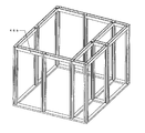
- FIG. 16 shows a partition-type three-sided partition using the building material connecting bracket 2 and the building material connecting bracket 3 according to the present invention. Due to the shape of sandwiching the central partition, the partition is self-supporting and stable.
- FIG. 17 shows a three-sided partition with storage of a partition type using the building material connecting bracket 2 and the building material connecting bracket 3 according to the present invention. Since the storage is provided, the functionality is improved, and a part of the wall surface of the partition is configured to be opened without inserting the plate portion, and there is a feeling of opening.
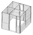
- FIG. 18 shows a box-type four-sided partition using the building material connecting bracket 2 and the building material connecting bracket 3 according to the present invention. Since it is a four-sided type, it is possible to produce a single room, and a part of the wall surface of the partition is configured to be opened without inserting a plate portion, and there is a feeling of opening.
- FIG. 19 shows a box-type four-sided partition using the building material connecting bracket 2 and the building material connecting bracket 3 according to the present invention. Since the arrangement of the beam portion is moved to the wall surface side, the feeling of openness on the vertical upper side is improved.
Abstract
Use is made of a building material joining metal fitting and building material for building material joining metal fitting that securely reproduce the post-beam right angle. Thus, there is provided a partition that can safely, securely and easily assembled, and are provided a building material joining metal fitting and building material for building material joining metal fitting that are used to construct the partition. The building material joining metal fitting comprises a pair of first mutually parallel flat plates opposite to each other with a given spacing therebetween and a pair of second mutually parallel flat plates opposite to each other with the same spacing as that of the first mutually parallel flat plates, arranged so as to cross the pair of first mutually parallel flat plates in double-cross perpendicular relationship, so that a frame section and four pairs of extension parts are provided. At least two pairs among these extension parts are provided with openings for building material fixing.
Description
本発明は、建材連結金具と建材連結金具用建材と組立間仕切とに関し、簡易に組立と設計変更ができる組立間仕切とこの組立間仕切を組み立てるのに最適な建材連結金具と建材連結金具用建材に関する。
The present invention relates to a building material connecting bracket, a building material for a building material connecting bracket, and an assembly partition, and more particularly to an assembly partition that can be easily assembled and changed in design, a building material connecting bracket that is optimal for assembling the assembly partition, and a building material for a building material connecting bracket.
室内を任意の広さの空間として画定するには間仕切りが用いられる。一般的には、壁から構成される、間仕切りや収納を含んで構成される間仕切りが数多く提案されている。
A partition is used to define the room as an arbitrarily large space. In general, many partitions composed of walls and including partitions and storage have been proposed.
例えば、より安価に構成でき、簡易な方法で家具まで収納できるようなトランクルームについては、例えば特許文献1において提案されている。このトランクルームでは、間仕切りの壁材として段ボールを使用することが提案されている。
For example, Patent Document 1 proposes a trunk room that can be configured at a lower cost and can store furniture by a simple method. In this trunk room, it has been proposed to use corrugated cardboard as a partition wall material.
また、特許文献2では、種々の要求に従って変更することができる高さ及び幅を有する、組立ユニットにより仕切りを提供することが開示されている。
Further, Patent Document 2 discloses that a partition is provided by an assembly unit having a height and a width that can be changed according to various requirements.
従来、住宅の部屋の内部の仕切を変更する場合、自ら家具やパーティッションを購入して配置するか、専門家に本格的な内装工事を依頼して変更するほか選択肢が存在しなかった。
Conventionally, when changing the interior partition of a residential room, there was no option other than purchasing and arranging furniture and partitions by themselves, or by requesting a full-scale interior construction from an expert.
図3(a)に示すように間仕切りを設けるために、柱を2本立設するのみでは水平力が加われば当然倒れることとなる。そこで、図3(b)に示すように2本の柱を1本の土台上に柱を立設するとともに、柱どうしを鉛直上側端部に梁を渡す必要がある。ところで、柱と梁は通常、垂直に交叉する。しかし、一般的な消費者にとって、梁と柱の間を正確に垂直に保ち、固定することは必ずしも容易ではなかった。梁と柱の間を正確に垂直に保ち、固定することは必ずしも容易でないにもかかわらず、この部分の垂直性は、間仕切りの完成品の質に多いに関係するものである。この点が、一般的な消費者が住宅の部屋の内部の仕切を変更する場合の大きな障壁となっている。特に間仕切りが複雑であればある程、複数の柱が生じ、その柱に対して最大で4本の梁を設けることができるため、柱数の増加によって消費者による間仕切りの設計と製造の困難性が著しく増大することとなる。
As shown in FIG. 3 (a), in order to provide a partition, if only two pillars are erected, it will naturally fall if a horizontal force is applied. Therefore, as shown in FIG. 3 (b), it is necessary to place the two columns upright on one base and pass the beam between the columns to the vertical upper end. By the way, columns and beams usually cross vertically. However, it has not always been easy for the general consumer to keep the beam and column exactly vertical and secure. Although it is not always easy to keep the beam and column exactly vertical and fixed, the verticality of this part is largely related to the quality of the finished partition. This is a big barrier when a general consumer changes the partition inside a residential room. In particular, the more complex the partition, the more columns will be created, and up to four beams can be provided for that column, making it difficult for consumers to design and manufacture partitions due to the increased number of columns. Will increase significantly.
そこで、本発明の目的は、柱と梁の直角を確実に形成することのできる建材連結金具と建材連結金具用建材を用いることで、安全で確実に容易に組立てることのできる間仕切りを提供する。さらに、それらを構成する建材連結金具と建材連結金具用建材を提供することにある。
Therefore, an object of the present invention is to provide a partition that can be assembled safely and surely and easily by using a building material connecting bracket and a building material for building material connecting bracket that can reliably form a right angle between a column and a beam. Furthermore, it is providing the building material connection metal fittings which comprise them, and the building material for building material connection metal fittings.
本発明に係る建材連結金具は、所定間隔で相対する一組の第一の平行平板と、
前記第一の平行平板と同一の間隔で相対して前記一組の第一の平行平板に対し井桁形状に直角に交叉する一組の第二の平行平板とから形成されることで枠部と4組の延在部が構成されて、これらの延在部のうち2組以上に建材固定用の開口部が開口する。 The building material connecting bracket according to the present invention includes a pair of first parallel flat plates facing each other at a predetermined interval,
The frame portion is formed by a pair of second parallel plates that intersect at right angles to the pair of first parallel plates at right angles to the pair of first parallel plates at the same interval as the first parallel plates. Four sets of extending portions are configured, and two or more sets of these extending portions have openings for fixing building materials.
前記平行平板は、幅と長さが互いにそれぞれ等しく、交叉する各平板同士は垂直に交叉してもよい。
The parallel plates may have the same width and length, and the intersecting plates may cross each other vertically.
前記開口部は、各平板の端部に鉛直方向で縦列に2つ以上開口することを特徴とする。
The opening is characterized in that two or more openings are opened vertically in the end of each flat plate.
前記開口部は、その開口径と略等しい口径のナットが各開口部に開口部の中心と前記ナットの中心が同一となるように溶着固定されることを特徴とする。また、前記延在部のうち梁と連結させる方向の延在部のみを延在させて、梁と連結しない方向の延在部を設けないことを特徴とする。
The opening is characterized in that a nut having a diameter substantially equal to the opening diameter is welded and fixed to each opening so that the center of the opening and the center of the nut are the same. Moreover, only the extension part of the direction connected with a beam is extended among the said extension parts, The extension part of the direction which is not connected with a beam is not provided, It is characterized by the above-mentioned.
本発明に係る建材連結金具用建材は、所定間隔で相対する一組の第一の平行平板と、前記第一の平行平板と同一の間隔で相対して前記一組の第一の平行平板に対し井桁形状に直角に交叉する一組の第二の平行平板とから形成されることで枠部と4組の延在部が構成されて、これらの延在部のうち2組以上に建材固定用の開口部が開口する建材連結金具によって梁部と連結するための柱部を含む建材連結金具用建材であって、前記柱部の頭部に前記柱部の一組の対向する側面と平行であって他の一組の側面に対しては垂直である前記第一の平行平板と同一の所定間隔で相対して刻設される一組の第一のスリットと、前記柱部の頭部に設けられて前記第一のスリットと同一の間隔で相対して前記一組の第一のスリットに対し井桁形状に直角に交叉する一組の第二のスリットと、が刻設される。
A building material for a building material connecting bracket according to the present invention has a pair of first parallel flat plates opposed to each other at a predetermined interval, and a pair of first parallel flat plates opposed to each other at the same interval as the first parallel flat plate. The frame part and four sets of extension parts are formed by forming a pair of second parallel plates that cross at right angles to the cross beam shape, and the building material is fixed to two or more of these extension parts. A construction material for a building material coupling bracket including a column portion for coupling to a beam portion by a building material coupling bracket having an opening for opening parallel to a pair of opposing side surfaces of the column portion at the head of the column portion A pair of first slits which are engraved at the same predetermined interval as the first parallel flat plate, which is perpendicular to the other set of side surfaces, and the heads of the pillars It is provided at the same interval as the first slit and intersects the pair of first slits at right angles in a cross-beam shape. And a pair of second slits, but is engraved.
前記スリットの幅が前記平行平板の厚みと同程度であることを特徴とする。
The width of the slit is approximately the same as the thickness of the parallel plate.
前記スリットの深さが前記平行平板の幅よりも深く、その深さが全スリットに渡り一定であることで建材連結金具柱部に対して水平に配置可能であることを特徴とする。
The depth of the slit is deeper than the width of the parallel plate, and the depth is constant over all the slits, so that the slit can be disposed horizontally with respect to the building material connecting bracket column.
前記柱部は、その側面に間仕切を挿入するための挿入溝を長手方向に刻設することを特徴とする。
The column part is characterized in that an insertion groove for inserting a partition is formed on the side surface in the longitudinal direction.
前記柱部は、その底部にホゾ突部が鉛直下向きに突設されることを特徴とする。
The columnar portion is characterized in that a ridge protrusion protrudes vertically downward at the bottom thereof.
前記柱部を立設する位置にホゾ穴が開口される土台部を備えることを特徴とする。
The base portion is provided with an opening at a position where the pillar portion is erected.
本発明に係る組立間仕切は、所定間隔で相対する一組の第一の平行平板と、前記第一の平行平板と同一の間隔で相対して前記一組の第一の平行平板に対し井桁形状に直角に交叉する一組の第二の平行平板とから形成されることで枠部と4組の延在部が構成されて、これらの延在部のうち2組以上に建材固定用の開口部が開口する建材連結金具と、前記建材連結金具によって梁部と連結するための柱部を含み、前記柱部の頭部に前記柱部の一組の対向する側面と平行であって他の一組の側面に対しては垂直である前記第一の平行平板と同一の所定間隔で相対して刻設される一組の第一のスリットと、前記柱部の頭部に設けられて前記第一のスリットと同一の間隔で相対して前記一組の第一のスリットに対し井桁形状に直角に交叉する一組の第二のスリットとが刻設される建材連結金具用建材と、底部に敷設される土台部と、建材連結金具の端部に固定される一組の梁部と、前記建材連結金具用建材の側面に刻設される溝部に嵌め込まれる板部とからなり、前記建材連結金具用建材はその底面にホゾ突部を突設して土台部に設けられたホゾ穴に立設されて形成される。
前記梁部は、その幅が前記柱部の幅と異なるとともに前記柱部の両外面側にそれぞれの前記一組の梁部を合い向かい合うように設けてもよい。また、前記一組の梁部と前記隣り合う柱部に囲まれた空間に少なくとも一枚以上の鏡板材を挿入してもよい。 The assembly partition according to the present invention includes a pair of first parallel plates opposed to each other at a predetermined interval, and a cross-beam shape relative to the set of first parallel plates opposed to each other at the same interval as the first parallel plates. Are formed from a pair of second parallel flat plates that intersect at right angles to each other to form a frame portion and four sets of extending portions, and two or more sets of these extending portions have openings for fixing building materials. Including a building material coupling bracket having an opening and a column portion for coupling to the beam portion by the building material coupling bracket, parallel to a pair of opposing side surfaces of the column portion at the head of the column portion, A set of first slits that are engraved at the same predetermined interval as the first parallel plate that is perpendicular to the set of side surfaces; A pair of second crossing at right angles to the pair of first slits at the same interval as the first slit. A building material for a building material connecting bracket in which a slit is engraved, a base portion laid at the bottom, a pair of beams fixed to an end of the building material connecting bracket, and a side surface of the building material for the building material connecting bracket. The building material for the building material connecting bracket is formed by projecting a tenon projecting portion on the bottom surface thereof and standing up in a tenon hole provided in the base portion.
The beam portions may be provided so that the width of the beam portions is different from the width of the column portions and the pair of beam portions are opposed to each other on both outer surface sides of the column portions. Further, at least one end plate member may be inserted into a space surrounded by the pair of beam portions and the adjacent column portions.
本発明に係る建材連結金具と建材連結金具用建材を用いることで、柱と梁の直角を確実に再現でき、安全で確実に容易に間仕切りを組立てることができるという利点がある。
By using the building material connecting bracket and the building material connecting bracket according to the present invention, there is an advantage that the right angle between the column and the beam can be reliably reproduced, and the partition can be assembled safely and reliably.
2 建材連結金具
4、6 第一の平行平板
8、10 第二の平行平板
12 開口部
12a、12b 開口部
12c、12d 開口部
12e、12f 開口部
12g、12h 開口部
12e、12f、12i,12j 開口部
12g、12h、12k,12l 開口部
14 ナット
14a、14b ナット
14c、14d ナット
14e、14f ナット
14g、14h ナット
14e、14f、14i、14j ナット
14g、14h、14k、14l ナット
16 建材連結金具用建材
18 柱部
20 頭部
22,24 側面
26,28 側面
30、32 第一のスリット
34、36 第二のスリット
18a 柱部
18b 柱部
18c 柱部
18d 柱部
18e 柱部
18f 柱部
18g 柱部
18h 柱部
18j 柱部
18i 柱部
2a、2b、2c、2d、2e、2f、2g、2h、2i、2j 建材連結金具
40、42 梁部
46a、44a 梁部
46b、44b 梁部
48a、48b 梁部
50a、50b 梁部
52a、52b 梁部
54a、54b 梁部
56a、56b 梁部
58a、58b 梁部
60a、60b 梁部
62a、62b 梁部
64a、64b 梁部
66a、66b 梁部
68 土台部
70 土台部
71 土台枠
72 土台部
74 土台部
76 土台部
80 土台部
82a、82c ホゾ穴
82b ホゾ穴
82d ホゾ穴
82g ホゾ穴
82h、82j ホゾ穴
82i ホゾ穴
82k ホゾ穴
82l ホゾ穴 2 Building material connecting brackets 4, 6 First parallel flat plate 8, 10 Second parallel flat plate 12 Opening portions 12a, 12b Opening portions 12c, 12d Opening portions 12e, 12f Opening portions 12g, 12h Opening portions 12e, 12f, 12i, 12j Opening 12g, 12h, 12k, 12l Opening 14 Nut 14a, 14b Nut 14c, 14d Nut 14e, 14f Nut 14g, 14h Nut 14e, 14f, 14i, 14j Nut 14g, 14h, 14k, 14l Nut 16 For building material connecting bracket Building material 18 Column 20 Head 22, 24 Side 26, 28 Side 30, 32 First slit 34, 36 Second slit 18a Column 18b Column 18c Column 18d Column 18e Column 18e Column 18f Column 18g Column 18h Column 18j Column 18i Column 2a, 2b, 2c, 2d, 2e, 2f, 2g, 2h, 2h i, 2j Building material connecting brackets 40, 42 Beams 46a, 44a Beams 46b, 44b Beams 48a, 48b Beams 50a, 50b Beams 52a, 52b Beams 54a, 54b Beams 56a, 56b Beams 58a, 58b Beams Parts 60a, 60b beam parts 62a, 62b beam parts 64a, 64b beam parts 66a, 66b beam parts 68 base part 70 base part 71 base frame 72 base part 74 base part 76 base part 80 base part 82a, 82c side hole 82b side hole 82d Side hole 82g Side hole 82h, 82j Side hole 82i Side hole 82k Side hole 82l Side hole
4、6 第一の平行平板
8、10 第二の平行平板
12 開口部
12a、12b 開口部
12c、12d 開口部
12e、12f 開口部
12g、12h 開口部
12e、12f、12i,12j 開口部
12g、12h、12k,12l 開口部
14 ナット
14a、14b ナット
14c、14d ナット
14e、14f ナット
14g、14h ナット
14e、14f、14i、14j ナット
14g、14h、14k、14l ナット
16 建材連結金具用建材
18 柱部
20 頭部
22,24 側面
26,28 側面
30、32 第一のスリット
34、36 第二のスリット
18a 柱部
18b 柱部
18c 柱部
18d 柱部
18e 柱部
18f 柱部
18g 柱部
18h 柱部
18j 柱部
18i 柱部
2a、2b、2c、2d、2e、2f、2g、2h、2i、2j 建材連結金具
40、42 梁部
46a、44a 梁部
46b、44b 梁部
48a、48b 梁部
50a、50b 梁部
52a、52b 梁部
54a、54b 梁部
56a、56b 梁部
58a、58b 梁部
60a、60b 梁部
62a、62b 梁部
64a、64b 梁部
66a、66b 梁部
68 土台部
70 土台部
71 土台枠
72 土台部
74 土台部
76 土台部
80 土台部
82a、82c ホゾ穴
82b ホゾ穴
82d ホゾ穴
82g ホゾ穴
82h、82j ホゾ穴
82i ホゾ穴
82k ホゾ穴
82l ホゾ穴 2 Building
以下に、この発明の実施形態例を、図面を用いて説明する。
Hereinafter, embodiments of the present invention will be described with reference to the drawings.
図1、2に本発明に係る建材連結金具を示す。本発明に係る建材連結金具2は、所定間隔で相対する一組の第一の平行平板4、6と、前記第一の平行平板4、6と同一の間隔で相対して前記一組の第一の平行平板4、6に対し井桁形状に直角に交叉する一組の第二の平行平板8、10とから形成されることで枠部5と4組の延在部(平行平板6に対して6a)が構成されて、これらの延在部のうち、2組以上に建材固定用の開口部12が開口する。
1 and 2 show a construction material connecting bracket according to the present invention. The building material connecting bracket 2 according to the present invention includes a pair of first parallel flat plates 4 and 6 facing each other at a predetermined interval, and the pair of first parallel flat plates 4 and 6 facing each other at the same interval. It is formed of a pair of second parallel flat plates 8 and 10 that intersect at right angles to a parallel plate shape with respect to one parallel flat plate 4 and 6, so that a frame portion 5 and four sets of extending portions (relative to the parallel flat plate 6). 6a) is configured, and among these extended parts, the building material fixing openings 12 are opened in two or more sets.
図1に示す建材連結金具2は、角部用の金具であり、第一の平行平板4、6と第二の平行平板8、10の一端が切断されて、井桁形状における枠部5のみが残されて第一の平行平板4、6とを第二の平行平板8、10は、いずれも交叉点から他端までである延在部が切断され、井桁形状の隣接する二組の延在部が残されることで上部から閲覧するとL字形状に構成される。
The building material connecting bracket 2 shown in FIG. 1 is a bracket for a corner, and one end of the first parallel flat plates 4 and 6 and the second parallel flat plates 8 and 10 are cut, and only the frame portion 5 in the cross beam shape is provided. The first parallel flat plates 4 and 6 and the second parallel flat plates 8 and 10 are both cut off from the crossing point to the other end, and two sets of adjacent extensions in the form of a cross beam When the part is left and viewed from above, it is configured in an L shape.
また、開口部12に対して、第一の平行平板4、6の各対向する側にナット14が開口部12に溶着される。図1では、第一の平行平板4に短辺に沿って1列に2つの開口部12a、12bが開口され、第一の平行平板4の第一の平行平板6側に、ナット14a、14b(図示せず)が溶着されている。同様に第一の平行平板6に短辺に沿って1列に2つの開口部12c、12d(図示せず)が開口され、第一の平行平板6の第一の平行平板4側に、ナット14c(図示あり)、14d(図示せず)が溶着されている。さらに、第二の平行平板8に短辺に沿って1列に2つの開口部12e、12f(図示せず)が開口され、第二の平行平板8の第二の平行平板10側に、ナット14e、14fが溶着されている。同様に第二の平行平板10に短辺に沿って1列に2つの開口部12g、12hが開口され、第二の平行平板10の第一の平行平板8側に、ナット14g、14h(図示せず)が溶着されている。
Also, a nut 14 is welded to the opening 12 on each facing side of the first parallel plates 4 and 6 with respect to the opening 12. In FIG. 1, two openings 12 a and 12 b are opened in a row along the short side of the first parallel plate 4, and nuts 14 a and 14 b are formed on the first parallel plate 6 side of the first parallel plate 4. (Not shown) is welded. Similarly, two openings 12c and 12d (not shown) are opened in a row along the short side of the first parallel plate 6 and nuts are formed on the first parallel plate 4 side of the first parallel plate 6. 14c (shown) and 14d (not shown) are welded. Furthermore, two openings 12e and 12f (not shown) are opened in a row along the short side of the second parallel flat plate 8, and a nut is formed on the second parallel flat plate 10 side of the second parallel flat plate 8. 14e and 14f are welded. Similarly, two openings 12g and 12h are opened in a row along the short side of the second parallel flat plate 10, and nuts 14g and 14h (see FIG. (Not shown) is welded.
第一の平行平板4と6との配置間隔と第二の平行平板8と10との配置間隔は同一の間隔l1で示され、このl1の値は柱部となる建材連結金具用建材の幅より短く設定され、スリットと同一の間隔に設定される。
The arrangement interval between the first parallel flat plates 4 and 6 and the arrangement interval between the second parallel flat plates 8 and 10 are indicated by the same interval l1, and the value of l1 is the width of the building material for the building material connecting bracket that becomes the column portion. It is set shorter and set at the same interval as the slit.
第一の平行平板4、6、第二の平行平板8、10の幅は、接続される梁の幅よりも狭く設定される。また、第一の平行平板4、6、第二の平行平板8、10は、柱部となる建材連結金具用建材のスリットの深さよりは十分狭い。
The widths of the first parallel plates 4 and 6 and the second parallel plates 8 and 10 are set narrower than the width of the beam to be connected. Moreover, the 1st parallel flat plates 4 and 6 and the 2nd parallel flat plates 8 and 10 are sufficiently narrower than the depth of the slit of the building material for building material connection metal fittings used as a pillar part.
第一の平行平板4、6、第二の平行平板8、10の長さは、梁部と重なる部分の長さと、柱部となる建材連結金具用建材に埋設される部分の長さとを加えた値である。第一の平行平板4、6、第二の平行平板8、10の長さから、第一の平行平板4と6との配置間隔と第二の平行平板8と10との配置間隔を除いた間隔は前記配置間隔より長めに設定される。
The lengths of the first parallel flat plates 4 and 6 and the second parallel flat plates 8 and 10 are added to the length of the portion overlapping the beam portion and the length of the portion embedded in the building material for the building material connecting bracket as the column portion. Value. The arrangement interval between the first parallel plates 4 and 6 and the arrangement interval between the second parallel plates 8 and 10 are excluded from the lengths of the first parallel plates 4 and 6 and the second parallel plates 8 and 10. The interval is set longer than the arrangement interval.
図2に示す建材連結金具2は、T字結合部の金具であり、第一の平行平板4、6の一端のみが切断されて、上部から閲覧すると鳥居形状に構成される。このため、第二の平行平板8、10両端に開口部があり、それぞれ、第二の平行平板8には、一端、開口部12e(図示せず)と12f(図示せず)と他端に12i(図示せず)と12j(図示せず)が設けられており、それら開口部の第二の平行平板10側にはナット14e、14f、14i、14j(図示せず)が溶接される。一方で、第二の平行平板10には、一端、開口部12gと12h(いずれもボルトが挿入されており図示せず)と他端に12k,12l(図示せず)が設けられており、それら開口部の第二の平行平板8側にはナット14g、14h、14k、14l(図示せず)が溶接される。
The building material connecting bracket 2 shown in FIG. 2 is a bracket of a T-shaped coupling part, and only one end of the first parallel plates 4 and 6 is cut, and when viewed from above, it is configured in a torii shape. For this reason, there are openings at both ends of the second parallel flat plate 8 and 10, and the second parallel flat plate 8 has one end, an opening 12e (not shown) and 12f (not shown), and the other end, respectively. 12i (not shown) and 12j (not shown) are provided, and nuts 14e, 14f, 14i, and 14j (not shown) are welded to the second parallel flat plate 10 side of the openings. On the other hand, the second parallel plate 10 is provided with one end, openings 12g and 12h (both are not shown with bolts inserted) and 12k and 12l (not shown) at the other end. Nuts 14g, 14h, 14k, 14l (not shown) are welded to the second parallel flat plate 8 side of the openings.
続いて、図4に本発明に係る建材連結金具用建材16を示す。この建材連結金具用建材16は、前記柱部18の頭部20に前記柱部18の一組の対向する側面22,24と平行であって他の一組の側面26,28に対しては垂直に第一のスリット30、32が前記柱部の頭部20から軸方向鉛直下向きに刻設される。第一のスリット30、32が第一の平行平板4、6に対応するスリットである。
Subsequently, FIG. 4 shows a building material 16 for a building material connecting bracket according to the present invention. This building material connecting metal fitting 16 is parallel to a pair of opposing side surfaces 22 and 24 of the column portion 18 on the head portion 20 of the column portion 18, and to the other set of side surfaces 26 and 28. First slits 30 and 32 are vertically cut from the head portion 20 of the column portion vertically downward in the axial direction. The first slits 30 and 32 are slits corresponding to the first parallel plates 4 and 6.
第一のスリット30と第一のスリット32の間隔は、前記第一の平行平板4、6と同一の所定間隔l1である。第一のスリット30、32の長手方向の長さは、前記柱部18の幅と同一であり、第一のスリット30、32の幅は、前記第一の平行平板4、6の厚みと略同一であり、第一のスリット30、32の深さは、第一の平行平板4、6の幅より大きく3倍よりは小さい。第一のスリット30、32は、側面22と側面24の中心線に対して線対称となるように配置される。また、第一のスリット30、32の底面は、前記柱部18の底面と平行に形成される。このため、建材連結金具2の水平性を容易に保持可能となる。
The interval between the first slit 30 and the first slit 32 is the same predetermined interval 11 as that of the first parallel plates 4 and 6. The lengths of the first slits 30 and 32 in the longitudinal direction are the same as the width of the column portion 18, and the widths of the first slits 30 and 32 are substantially the same as the thicknesses of the first parallel plates 4 and 6. The depths of the first slits 30 and 32 are the same as those of the first parallel plates 4 and 6 and are smaller than 3 times. The first slits 30 and 32 are arranged so as to be line symmetric with respect to the center line of the side surface 22 and the side surface 24. The bottom surfaces of the first slits 30 and 32 are formed in parallel with the bottom surface of the column part 18. For this reason, it becomes possible to easily maintain the horizontality of the building material coupling fitting 2.
一方、第一のスリット30、32と井桁形状に直角に交叉するのは、一組の第二のスリット34、36である。第二のスリット34、36は、第二の平行平板8、10に対応するスリットである。第二のスリット34、36の長手方向の長さは、前記柱部18の幅と同一であり、第二のスリット34、36の幅は、前記第二の平行平板8、10の厚みと略同一であり、第二のスリット34、36の深さは、第二の平行平板8、10の幅より大きく3倍よりは小さく、第一の平行平板4、6の深さとも等しい。このため、建材連結金具2の水平性を確実に確保することができる。第二のスリット34、36は、側面26と側面28の中心線に対して線対称となるように配置される。また、第二のスリット34、36の底面は、前記柱部18の底面と平行に形成される。
On the other hand, a set of second slits 34 and 36 intersects the first slits 30 and 32 at right angles to the cross beam shape. The second slits 34 and 36 are slits corresponding to the second parallel flat plates 8 and 10. The lengths of the second slits 34 and 36 in the longitudinal direction are the same as the width of the column portion 18, and the widths of the second slits 34 and 36 are substantially the same as the thicknesses of the second parallel plates 8 and 10. The depth of the second slits 34 and 36 is the same as that of the second parallel plates 8 and 10 and less than 3 times, and is equal to the depth of the first parallel plates 4 and 6. For this reason, the horizontality of the building material coupling fitting 2 can be reliably ensured. The second slits 34 and 36 are arranged so as to be line symmetric with respect to the center line of the side surface 26 and the side surface 28. The bottom surfaces of the second slits 34 and 36 are formed in parallel with the bottom surface of the column part 18.
なお、柱部の四側面には矢羽形状板を挟み込む溝部37が柱軸方向に刻設される。
In addition, the groove part 37 which pinches | interposes an arrow feather-shaped board is engraved on the four side surfaces of the column part in the column axis direction.
図5、6に本発明に係る建材連結金具2と建材連結金具用建材3とを組み合わせた組立図を示す。
FIGS. 5 and 6 show assembly drawings in which the building material connecting bracket 2 and the building material connecting bracket 3 according to the present invention are combined.
図5では、柱部18に第一のスリット30、32が刻設されており、この第一のスリット30、32にそれぞれ、建材連結金具2の第一の平行平板4、6が挿入されている。この第一の平行平板4、6には梁部40、42がナット14a、14b、14c、14dにボルトで固定される。一方、第二の平行平板10には、梁部44が開口部12g、12hの位置に置いてボルト止め固定される。ここで、柱部18と建材連結金具2が水平に連結されることで、柱部18と梁部44が垂直に連結することができる。また、ナット14a、14b、14c、14dはいずれも第一の平行平板4、6の内側に配置されているため、装着する際にボルトのみを外側から容易に装着することができる。また、柱部18の四側面には矢羽形状板を挟み込む溝部37が柱軸方向に刻設される。
In FIG. 5, the first slits 30 and 32 are engraved in the column portion 18, and the first parallel flat plates 4 and 6 of the building material coupling fitting 2 are inserted into the first slits 30 and 32, respectively. Yes. Beam portions 40 and 42 are fixed to the nuts 14a, 14b, 14c and 14d with bolts on the first parallel flat plates 4 and 6, respectively. On the other hand, the beam portion 44 is placed on the second parallel flat plate 10 at the positions of the openings 12g and 12h and fixed with bolts. Here, the column part 18 and the building material coupling fitting 2 are connected horizontally, whereby the column part 18 and the beam part 44 can be connected vertically. Further, since the nuts 14a, 14b, 14c, and 14d are all disposed inside the first parallel plates 4 and 6, only the bolts can be easily mounted from the outside when they are mounted. Further, on the four side surfaces of the column portion 18, groove portions 37 that sandwich the arrow-shaped plate are engraved in the column axis direction.
一方、図6では、さらに、梁部44aに鳥居形状の建材連結金具2aが連結されて、この建材連結金具2aが柱部18bに固定されるとともにさらなる梁部44bに連結されるものである。ここでも、建材連結金具2aは柱部18bに水平に配置されるため、梁部44bと垂直を保持することができる。
On the other hand, in FIG. 6, the torii-shaped building material connecting bracket 2a is further connected to the beam portion 44a, and the building material connecting bracket 2a is fixed to the column portion 18b and connected to the further beam portion 44b. Also here, since the building material connecting bracket 2a is arranged horizontally on the column portion 18b, it can hold the beam portion 44b and the vertical direction.
さらに、図7に本発明に係る間仕切りにおける梁部と柱部と建材連結金具の構成について説明する。外枠は、柱部18aと柱部18cと柱部18hと柱部18jが四隅に設けられ、柱部18aと柱部18cとの間に柱部18bが立設され、柱部18cと柱部18hとの間に柱部18dが立設され、柱部18hと柱部18jとの間に柱部18iが立設され、柱部18jと柱部18aとの間に柱部18gが立設され、柱部18dと柱部18gとの間に柱部18fが立設され、柱部18dと柱部18fとの間に柱部18eが立設される。
Furthermore, FIG. 7 demonstrates the structure of the beam part in the partition which concerns on this invention, a pillar part, and a building material coupling metal fitting. In the outer frame, a pillar part 18a, a pillar part 18c, a pillar part 18h, and a pillar part 18j are provided at four corners, and a pillar part 18b is erected between the pillar part 18a and the pillar part 18c. A column 18d is erected between 18h, a column 18i is erected between the column 18h and the column 18j, and a column 18g is erected between the column 18j and the column 18a. A column portion 18f is erected between the column portion 18d and the column portion 18g, and a column portion 18e is erected between the column portion 18d and the column portion 18f.
この各柱18a、18b、18c、18d、18e、18g、18h、18i、18jの頭部にはそれぞれ、1つの建材連結金具2a、2b、2c、2d、2e、2f、2g、2h、2i、2jが装着される。
On the heads of the pillars 18a, 18b, 18c, 18d, 18e, 18g, 18h, 18i, 18j, one building material connecting bracket 2a, 2b, 2c, 2d, 2e, 2f, 2g, 2h, 2i, 2j is mounted.
柱18aと柱18bとの間には梁部46a、44aが架設され、柱18bと柱18cとの間には梁部46b、44bが架設され、柱18cと柱18dとの間には梁部48a、48bが架設され、柱18dと柱18eとの間には梁部62a、62bが架設され、柱18eと柱18fとの間には梁部64a、64bが架設され、柱18fと柱18gとの間には梁部66a、66bが架設され、柱18dと柱18hとの間には梁部50a、50bが架設され、柱18hと柱18iとの間には梁部52a、52bが架設され、柱18iと柱18jとの間には梁部54a、54bが架設され、柱18jと柱18gとの間には梁部56a、56bが架設され、柱18gと柱18aとの間には梁部40、42が架設され、柱18bと柱18fとの間には梁部60a、60bが架設され、柱18fと柱18iとの間には梁部58a、58bが架設される。いずれも、各柱に設けられるスリットにより、水平を保つ梁部が形成される。
Beam portions 46a and 44a are installed between the columns 18a and 18b, beam portions 46b and 44b are installed between the columns 18b and 18c, and beam portions are provided between the columns 18c and 18d. 48a and 48b are erected, beam portions 62a and 62b are erected between the column 18d and the column 18e, beam portions 64a and 64b are erected between the column 18e and the column 18f, and the column 18f and the column 18g. The beam portions 66a and 66b are installed between the columns 18d and 18h, the beam portions 50a and 50b are installed between the columns 18d and 18h, and the beam portions 52a and 52b are installed between the columns 18h and 18i. The beam portions 54a and 54b are installed between the columns 18i and 18j, the beam portions 56a and 56b are installed between the columns 18j and 18g, and between the columns 18g and 18a. Beam portions 40 and 42 are installed, and a beam is provided between the column 18b and the column 18f. 60a, 60b are laid, the beam portion 58a, 58b is bridged between the pillars 18f and the bar 18i. In any case, a beam portion that is kept horizontal is formed by a slit provided in each column.
なお、図8に示すように建材連結金具2a、2c、2h、2jは、隣り合う二組の平行平板のみに平板部が残されて開口部が設けられ、残り二組の平行平板は枠部のみとされ開口部も存在しないL字形状に構成される。
In addition, as shown in FIG. 8, the building material coupling fittings 2a, 2c, 2h, and 2j are provided with openings by leaving the flat plate portions only in two adjacent parallel flat plates, and the remaining two sets of parallel flat plates are frame portions. It is comprised only in L shape which does not have an opening part.
一方、建材連結金具2b、2d、2i、2gは、三組の平行平板の平板部が残されて開口部が設けられ、残り一組の平行平板は枠部のみとされ開口部も存在しない鳥居字形状に構成される。
On the other hand, the building material connecting brackets 2b, 2d, 2i, and 2g are provided with openings by leaving the flat plate portions of three sets of parallel flat plates, and the remaining one set of parallel flat plates is only a frame portion and there is no opening portion. It is configured in a letter shape.
さらに、建材連結金具2e、2fは、いずれの平行平板も切断されない完全な井桁形状に構成される。
Furthermore, the building material connecting brackets 2e and 2f are configured in a perfect cross beam shape in which neither parallel plate is cut.
続いて図9~13を参照して、本発明に係る建材連結金具2と建材連結金具用建材3とを用いて組立型間仕切り1を組み立てる方法について説明する。
Subsequently, a method of assembling the assembly type partition 1 using the building material connecting bracket 2 and the building material connecting bracket building material 3 according to the present invention will be described with reference to FIGS.
まず、本発明に係る間仕切りを配置する部屋に土台枠71を配列する。図9においては、相対して平行に二辺の土台部70と72が配列され、この土台部70と72と結合されるように相対して平行に二辺の土台部74、76が配列される。さらに、土台部74と76との間であって、土台部76に近接して平行に土台部68が配列される。土台部76と土台部68が連結するように土台部80が配列される。なお、この土台部70、72、74、76、78、80には、ホゾ穴が設けられている。具体的には、土台部70には両端にホゾ穴82a、82cが刻設され、中央にホゾ穴82kが刻設され、土台部70部と土台部78の連結点にホゾ穴82bが刻設される。一方、土台部72には、両端にホゾ穴82h、82jが刻設され、中間にホゾ穴82lが刻設され、土台部72部と土台部78の連結点にホゾ穴82iが刻設される。一方、土台部74はその中間にホゾ穴82dが刻設される。土台部76はその中間にホゾ穴82gが刻設される。土台部78はその中間にホゾ穴82fが刻設される。
First, the base frame 71 is arranged in a room in which the partitions according to the present invention are arranged. In FIG. 9, two sides of the base portions 70 and 72 are arranged in parallel with each other, and two sides of the base portions 74 and 76 are arranged in parallel with each other so as to be coupled to the base portions 70 and 72. The Further, a base portion 68 is arranged in parallel between the base portions 74 and 76 and close to the base portion 76. The base part 80 is arranged so that the base part 76 and the base part 68 are connected. The foundation portions 70, 72, 74, 76, 78, and 80 are provided with side holes. Specifically, the base part 70 is engraved with tenon holes 82a and 82c at both ends, the center is provided with an elbow hole 82k, and the base part 70 and the base part 78 are engraved with a tenon hole 82b. Is done. On the other hand, the base portion 72 is engraved with tenon holes 82h and 82j at both ends, an intermediate tenon hole 82l is engraved, and a tenon hole 82i is engraved at the connecting point between the base portion 72 and the base portion 78. . On the other hand, the base portion 74 is provided with a relief hole 82d in the middle. The base portion 76 is engraved with a relief hole 82g in the middle. A base hole 78 f is engraved in the middle of the base portion 78.
次に図10に示されるように、各柱部18a、18b、18k、18c、18d、18h、18l、18i、18j、18g、18fの先端のスリットに、対応する建材連結金具2a、2b、2k、2c、2d、2h、2l、2i、2j、2g、2fを装着する。
Next, as shown in FIG. 10, the building material connecting brackets 2a, 2b, 2k corresponding to the slits at the tips of the pillars 18a, 18b, 18k, 18c, 18d, 18h, 18l, 18i, 18j, 18g, 18f are provided. 2c, 2d, 2h, 2l, 2i, 2j, 2g, and 2f are attached.
ここで、建材連結金具用建材において柱部の長さは1950mmであり、90mm×90mmの角材を使用する。また、スリット同士の間隔は、50mm程度に構成され、スリットの幅は3mmから5mm程度である。ここで、建材連結金具2が柱部に装着されて緊結されるようにするため、スリットの幅は5mm以下とすることが好ましい。
Here, in the building material for building material connecting bracket, the length of the column part is 1950 mm, and a square material of 90 mm × 90 mm is used. Moreover, the space | interval of slits is comprised about 50 mm, and the width | variety of a slit is about 3 mm to 5 mm. Here, it is preferable that the width of the slit is 5 mm or less so that the building material connecting bracket 2 is attached to the column portion and is tightly coupled.
建材連結金具について、平行平板の長手方向の長さは最長で170mmであり、枠部は50mm程度であり、開口部を備える井桁部は60mm程度である。平行平板の幅は、60mm程度である。また、建材連結金具2に設ける開口部は梁部との結合において、回転防止のため、平行平板の幅方向に2つ以上開口させて梁部と2つ以上ボルト止め固定することが好ましい。
For the building material connecting bracket, the length of the parallel plate in the longitudinal direction is 170 mm at the longest, the frame part is about 50 mm, and the cross-girder part having the opening is about 60 mm. The width of the parallel plate is about 60 mm. In addition, it is preferable that two or more openings provided in the building material connecting bracket 2 are opened in the width direction of the parallel flat plate and are bolted and fixed to the beam part in order to prevent rotation in connection with the beam part.
図11に示すように、土台枠71の上に、建材連結金具を連結させた各柱部18a、18b、18k、18c、18d、18h、18l、18i、18j、18g、18fを立設させる。
As shown in FIG. 11, on the base frame 71, the pillar portions 18a, 18b, 18k, 18c, 18d, 18h, 18l, 18i, 18j, 18g, and 18f, to which the building material connecting brackets are connected, are erected.
図12に示すように、続いて、各建材連結金具2a、2b、2k、2c、2d、2h、2l、2i、2j、2g、2fと、梁部とを連結させる。ここで、前記梁部は、その幅が前記柱部の幅と異なるとともに前記柱部の両外面側にそれぞれの前記一組の梁部を合い向かい合うように設けられる。
As shown in FIG. 12, each of the building material connecting brackets 2 a, 2 b, 2 k, 2 c, 2 d, 2 h, 2 l, 2 i, 2 j, 2 g, and 2 f is then connected to the beam portion. Here, the beam portion has a width different from that of the column portion, and is provided so that the pair of beam portions face each other on both outer surface sides of the column portion.
さらに、図13に示すように梁部と柱部が連結されると、2枚の梁部の鉛直上部から、複数枚の矢羽形状鏡板材82を溝部37に沿って挿入する。間仕切りの壁面を塞ぐ等の目的となる面積を遮蔽できる程度まで、矢羽形状鏡板材82が挿入されて、完成する。
Furthermore, as shown in FIG. 13, when the beam portion and the column portion are connected, a plurality of arrow blade-shaped end plate members 82 are inserted along the groove portion 37 from vertically above the two beam portions. The arrow feather shaped end plate member 82 is inserted and completed to the extent that the target area such as closing the wall surface of the partition can be blocked.
更に、図14~図19において本発明に係る組立間仕切りの例について説明する。
Furthermore, an example of an assembly partition according to the present invention will be described with reference to FIGS.
図14は、本発明に係る建材連結金具2と建材連結金具用建材3を用いて一面構成の組立間仕切りの構成図である。自立させる支持部として、柱部を延長させて天井との間に新たな梁部が設けられている。この梁を天井に押圧させて組立間仕切りを固定するものである。さらに、間仕切りの壁面の一部は板部を挿入せずに開放するように構成されている。
FIG. 14 is a configuration diagram of an assembly partition having a one-surface configuration using the building material connecting bracket 2 and the building material connecting bracket 3 according to the present invention. As a supporting part for self-supporting, a new beam part is provided between the ceiling and the column part. This beam is pressed against the ceiling to fix the assembly partition. Furthermore, a part of the wall surface of the partition is configured to be opened without inserting the plate portion.
図15は、本発明に係る建材連結金具2と建材連結金具用建材3を用いた間仕切りタイプのT字型形状の2面型間仕切りである。間仕切り自体で自立するために天井押圧用の梁は必要としないが、連結用の筋かい型梁が設けられている。
FIG. 15 shows a partition type T-shaped two-sided partition using the building material connecting bracket 2 and the building material connecting bracket 3 according to the present invention. In order to be independent by the partition itself, a beam for pressing the ceiling is not required, but a bracing beam for connection is provided.
図16は、本発明に係る建材連結金具2と建材連結金具用建材3を用いた間仕切りタイプの3面型間仕切りである。中央の間仕切りを挟み込む形状であるため間仕切りの自立性と安定性が高い。
FIG. 16 shows a partition-type three-sided partition using the building material connecting bracket 2 and the building material connecting bracket 3 according to the present invention. Due to the shape of sandwiching the central partition, the partition is self-supporting and stable.
図17は、本発明に係る建材連結金具2と建材連結金具用建材3を用いた間仕切りタイプの収納付き3面型間仕切りである。収納があるため、機能性が向上するとともに、間仕切りの壁面の一部は板部を挿入せずに開放するように構成されており、開放感がある。
FIG. 17 shows a three-sided partition with storage of a partition type using the building material connecting bracket 2 and the building material connecting bracket 3 according to the present invention. Since the storage is provided, the functionality is improved, and a part of the wall surface of the partition is configured to be opened without inserting the plate portion, and there is a feeling of opening.
図18は、本発明に係る建材連結金具2と建材連結金具用建材3を用いたボックスタイプの4面型間仕切りである。4面型であるため、個室性が演出できるとともに、間仕切りの壁面の一部は板部を挿入せずに開放するように構成されており、開放感がある。
FIG. 18 shows a box-type four-sided partition using the building material connecting bracket 2 and the building material connecting bracket 3 according to the present invention. Since it is a four-sided type, it is possible to produce a single room, and a part of the wall surface of the partition is configured to be opened without inserting a plate portion, and there is a feeling of opening.
図19は、本発明に係る建材連結金具2と建材連結金具用建材3を用いたボックスタイプの4面型間仕切りである。梁部の配置を壁面側へ移動させたため鉛直上側の開放感が向上する。
FIG. 19 shows a box-type four-sided partition using the building material connecting bracket 2 and the building material connecting bracket 3 according to the present invention. Since the arrangement of the beam portion is moved to the wall surface side, the feeling of openness on the vertical upper side is improved.
Claims (14)
- 所定間隔で相対する一組の第一の平行平板と、
前記第一の平行平板と同一の間隔で相対して前記一組の第一の平行平板に対し井桁形状に直角に交叉する一組の第二の平行平板とから形成されることで枠部と4組の延在部が構成されて、これらの延在部のうち2組以上に建材固定用の開口部が開口する建材連結金具。 A pair of first parallel plates facing each other at a predetermined interval;
The frame portion is formed by a pair of second parallel plates that intersect at right angles to the pair of first parallel plates at right angles to the pair of first parallel plates at the same interval as the first parallel plates. A building material coupling bracket in which four sets of extending portions are configured, and two or more sets of these extending portions have openings for fixing building materials. - 前記平行平板は、幅と長さが互いにそれぞれ等しく、交叉する各平板同士は垂直に交叉することを特徴とする請求項1記載の建材連結金具。 The building material connecting bracket according to claim 1, wherein the parallel plates have the same width and length, and the intersecting plates cross each other vertically.
- 前記開口部は、各平板の端部に鉛直方向で縦列に2つ以上開口することを特徴とする請求項1記載の建材連結金具。 2. The building material connecting bracket according to claim 1, wherein two or more openings are opened in a vertical direction at an end of each flat plate.
- 前記開口部は、その開口径と略等しい口径のナットが各開口部に開口部の中心と前記ナットの中心が同一となるように溶着固定されることを特徴とする請求項1記載の建材連結金具。 The building material connection according to claim 1, wherein a nut having a diameter substantially equal to the opening diameter of the opening is welded and fixed to each opening so that the center of the opening and the center of the nut are the same. Hardware.
- 前記延在部のうち梁と連結させる方向の延在部のみを延在させて、梁と連結しない方向の延在部を設けないことを特徴とする請求項1記載の建材連結金具。 2. The building material coupling bracket according to claim 1, wherein only the extended portion in the direction to be connected to the beam is extended, and the extended portion in the direction not connected to the beam is not provided.
- 所定間隔で相対する一組の第一の平行平板と、
前記第一の平行平板と同一の間隔で相対して前記一組の第一の平行平板に対し井桁形状に直角に交叉する一組の第二の平行平板とから形成されることで枠部と4組の延在部が構成されて、これらの延在部のうち2組以上に建材固定用の開口部が開口する建材連結金具によって梁部と連結するための柱部を含む建材連結金具用建材であって、
前記柱部の頭部に前記柱部の一組の対向する側面と平行であって他の一組の側面に対しては垂直である前記第一の平行平板と同一の所定間隔で相対して刻設される一組の第一のスリットと、
前記柱部の頭部に設けられて前記第一のスリットと同一の間隔で相対して前記一組の第一のスリットに対し井桁形状に直角に交叉する一組の第二のスリットと、
が刻設される建材連結金具用建材。 A pair of first parallel plates facing each other at a predetermined interval;
The frame portion is formed by a pair of second parallel plates that intersect at right angles to the pair of first parallel plates at right angles to the pair of first parallel plates at the same interval as the first parallel plates. For building material connecting brackets comprising four sets of extending portions, and including pillar portions for connecting to beam portions by building material connecting brackets in which two or more sets of these extending portions have openings for fixing building materials open Building materials,
The head of the pillar part is opposed to the first parallel flat plate that is parallel to the pair of opposing side faces of the pillar part and perpendicular to the other pair of side faces at the same predetermined interval. A set of first slits to be engraved;
A set of second slits provided at the head of the column portion and intersecting the set of first slits at right angles to the set of first slits at the same interval as the first slit;
A building material for building material connecting brackets. - 前記スリットの幅が前記平行平板の厚みと同程度であることを特徴とする請求項6記載の建材連結金具用建材。 The building material for a building material connecting bracket according to claim 6, wherein a width of the slit is approximately the same as a thickness of the parallel plate.
- 前記スリットの深さが前記平行平板の幅よりも深く、その深さが全スリットに渡り一定であることで建材連結金具柱部に対して水平に配置可能であることを特徴とする請求項6記載の建材連結金具用建材。 The depth of the slit is deeper than the width of the parallel plate, and the depth is constant over all the slits, so that the slit can be disposed horizontally with respect to the building material connecting bracket column. The building material for building material connecting bracket described.
- 前記柱部は、その側面に間仕切を挿入するための挿入溝を長手方向に刻設することを特徴とする請求項6記載の建材連結金具用建材。 The building material for a building material connecting bracket according to claim 6, wherein the column part is provided with an insertion groove for inserting a partition in a longitudinal direction on a side surface thereof.
- 前記柱部は、その底部にホゾ突部が鉛直下向きに突設されることを特徴とする請求項6記載の建材連結金具用建材。 The building material for a building material coupling bracket according to claim 6, wherein the columnar portion has a bottom protrusion projecting vertically downward at the bottom thereof.
- 前記柱部を立設する位置にホゾ穴が開口される土台部を備えることを特徴とする請求項6記載の建材連結金具用建材。 The building material for a building material connecting bracket according to claim 6, further comprising a base part in which a tenon hole is opened at a position where the pillar part is erected.
- 所定間隔で相対する一組の第一の平行平板と、
前記第一の平行平板と同一の間隔で相対して前記一組の第一の平行平板に対し井桁形状に直角に交叉する一組の第二の平行平板とから形成されることで枠部と4組の延在部が構成されて、これらの延在部のうち2組以上に建材固定用の開口部が開口する建材連結金具と、
前記建材連結金具によって梁部と連結するための柱部を含み、前記柱部の頭部に前記柱部の一組の対向する側面と平行であって他の一組の側面に対しては垂直である前記第一の平行平板と同一の所定間隔で相対して刻設される一組の第一のスリットと、前記柱部の頭部に設けられて前記第一のスリットと同一の間隔で相対して前記一組の第一のスリットに対し井桁形状に直角に交叉する一組の第二のスリットとが刻設される建材連結金具用建材と、
底部に敷設される土台部と、建材連結金具の端部に固定される一組の梁部と、前記建材連結金具用建材の側面に刻設される溝部に嵌め込まれる板部とからなり、前記建材連結金具用建材はその底面にホゾ突部を突設して土台部に設けられたホゾ穴に立設されて形成される組立間仕切。 A pair of first parallel plates facing each other at a predetermined interval;
The frame portion is formed by a pair of second parallel plates that intersect at right angles to the pair of first parallel plates at right angles to the pair of first parallel plates at the same interval as the first parallel plates. 4 sets of extending parts are constructed, and a building material coupling bracket in which an opening for fixing building materials is opened in two or more of these extended parts,
It includes a column portion for connecting to the beam portion by the building material connecting bracket, and is parallel to a pair of opposing side surfaces of the column portion at the head of the column portion and perpendicular to the other set of side surfaces. A pair of first slits that are engraved relative to each other at the same predetermined interval as the first parallel plate, and a head that is provided at the head of the column portion at the same interval as the first slit. A building material for a building material connecting bracket, in which a pair of second slits that are crossed at right angles to the cross beam shape with respect to the set of first slits,
Comprising a base portion laid at the bottom, a set of beam portions fixed to the end of the building material connecting bracket, and a plate portion fitted in a groove portion engraved on the side surface of the building material for the connecting member The building material for the building material connecting bracket is an assembly partition formed by protruding a tenon projecting portion on the bottom surface and standing in a tenon hole provided in the base portion. - 前記梁部は、その幅が前記柱部の幅と異なるとともに前記柱部の両外面側にそれぞれの前記一組の梁部を合い向かい合うように設けることを特徴とする請求項12記載の組立間仕切。 13. The assembly partition according to claim 12, wherein the beam portion has a width different from that of the column portion, and the pair of beam portions are provided on both outer surface sides of the column portion so as to face each other. .
- 前記一組の梁部と前記隣り合う柱部に囲まれた空間に少なくとも一枚以上の鏡板材を挿入することを特徴とする請求項12記載の組立間仕切。 13. The assembly partition according to claim 12, wherein at least one end plate member is inserted into a space surrounded by the pair of beam portions and the adjacent column portions.
Priority Applications (2)
| Application Number | Priority Date | Filing Date | Title |
|---|---|---|---|
| PCT/JP2008/058673 WO2009136447A1 (en) | 2008-05-09 | 2008-05-09 | Building material joining metal fitting and built-up partition utilizing the same |
| JP2009550842A JPWO2009136447A1 (en) | 2008-05-09 | 2008-05-09 | Building material connecting bracket and assembly partition using the same |
Applications Claiming Priority (1)
| Application Number | Priority Date | Filing Date | Title |
|---|---|---|---|
| PCT/JP2008/058673 WO2009136447A1 (en) | 2008-05-09 | 2008-05-09 | Building material joining metal fitting and built-up partition utilizing the same |
Publications (1)
| Publication Number | Publication Date |
|---|---|
| WO2009136447A1 true WO2009136447A1 (en) | 2009-11-12 |
Family
ID=41264508
Family Applications (1)
| Application Number | Title | Priority Date | Filing Date |
|---|---|---|---|
| PCT/JP2008/058673 WO2009136447A1 (en) | 2008-05-09 | 2008-05-09 | Building material joining metal fitting and built-up partition utilizing the same |
Country Status (2)
| Country | Link |
|---|---|
| JP (1) | JPWO2009136447A1 (en) |
| WO (1) | WO2009136447A1 (en) |
Cited By (1)
| Publication number | Priority date | Publication date | Assignee | Title |
|---|---|---|---|---|
| CN105178447A (en) * | 2015-09-28 | 2015-12-23 | 沈阳建筑大学 | Homocentric-square shaped wood hidden type energy dissipation connection piece |
Citations (5)
| Publication number | Priority date | Publication date | Assignee | Title |
|---|---|---|---|---|
| JPH01146034A (en) * | 1987-11-30 | 1989-06-08 | Dai Ichi Horm Co Ltd | Base sinking preventive device |
| JPH07259185A (en) * | 1994-03-18 | 1995-10-09 | Nishikawa Hisato | Column beam joining structure of building |
| JP2003119905A (en) * | 2001-10-11 | 2003-04-23 | Hirata Kensetsu:Kk | Joint metal for construction |
| JP2003239401A (en) * | 2002-02-20 | 2003-08-27 | Yuji Takeda | Joint device of building component, framework structure of building and framework construction method |
| JP2006207340A (en) * | 2005-01-31 | 2006-08-10 | Free Kogyo Kk | Panel built-up type partition |
-
2008
- 2008-05-09 JP JP2009550842A patent/JPWO2009136447A1/en active Pending
- 2008-05-09 WO PCT/JP2008/058673 patent/WO2009136447A1/en active Application Filing
Patent Citations (5)
| Publication number | Priority date | Publication date | Assignee | Title |
|---|---|---|---|---|
| JPH01146034A (en) * | 1987-11-30 | 1989-06-08 | Dai Ichi Horm Co Ltd | Base sinking preventive device |
| JPH07259185A (en) * | 1994-03-18 | 1995-10-09 | Nishikawa Hisato | Column beam joining structure of building |
| JP2003119905A (en) * | 2001-10-11 | 2003-04-23 | Hirata Kensetsu:Kk | Joint metal for construction |
| JP2003239401A (en) * | 2002-02-20 | 2003-08-27 | Yuji Takeda | Joint device of building component, framework structure of building and framework construction method |
| JP2006207340A (en) * | 2005-01-31 | 2006-08-10 | Free Kogyo Kk | Panel built-up type partition |
Cited By (2)
| Publication number | Priority date | Publication date | Assignee | Title |
|---|---|---|---|---|
| CN105178447A (en) * | 2015-09-28 | 2015-12-23 | 沈阳建筑大学 | Homocentric-square shaped wood hidden type energy dissipation connection piece |
| CN105178447B (en) * | 2015-09-28 | 2018-05-04 | 沈阳建筑大学 | The concealed energy consumption connector of rectangular-ambulatory-plane timber structure |
Also Published As
| Publication number | Publication date |
|---|---|
| JPWO2009136447A1 (en) | 2011-09-01 |
Similar Documents
| Publication | Publication Date | Title |
|---|---|---|
| KR100914742B1 (en) | A module of prefabricated building and a construction system using the same and a method of construction | |
| US20110272541A1 (en) | Outside wrap post coupler accommodating beam rivet | |
| JP6594932B2 (en) | Column fixing bracket | |
| WO2009136447A1 (en) | Building material joining metal fitting and built-up partition utilizing the same | |
| JP3406472B2 (en) | fence | |
| JP5123603B2 (en) | Unit type building and construction method of unit type building | |
| JP7475675B2 (en) | Strength-bearing column unit and improved wooden frame structure incorporating said strength-bearing column unit, and construction method thereof | |
| JP2008261160A (en) | Container house and its production method | |
| JP2011052507A (en) | Low-story building | |
| JP4779419B2 (en) | Structure | |
| JP2008069515A (en) | Sound insulation fence | |
| JP3625468B1 (en) | Column base structure, connection structure between column and horizontal member, and frame structure | |
| JPH07259185A (en) | Column beam joining structure of building | |
| JP3171173U (en) | Blindfold fence | |
| JP4749611B2 (en) | Unit type building and its construction method | |
| JP3114847B2 (en) | Fire fence for gas station | |
| JP6079446B2 (en) | Bearing walls and houses | |
| JP2807206B2 (en) | Exterior wall panels | |
| JP2003253760A (en) | Bearing wall structure of building | |
| WO2001009451A1 (en) | Wall structural body and method of manufacturing the wall structural body | |
| JPH08277587A (en) | Framework bearing wall and frame work construction method based on its application | |
| JP6359963B2 (en) | Slit screen type exterior packaging jig, slit screen type exterior construction method, and slit screen type exterior | |
| JP2978446B2 (en) | Middle pillar housing unit | |
| JPH07102685A (en) | Wall panel and frame for wall panel | |
| JP2807207B2 (en) | Exterior wall panels |
Legal Events
| Date | Code | Title | Description |
|---|---|---|---|
| WWE | Wipo information: entry into national phase |
Ref document number: 2009550842 Country of ref document: JP |
|
| 121 | Ep: the epo has been informed by wipo that ep was designated in this application |
Ref document number: 08752556 Country of ref document: EP Kind code of ref document: A1 |
|
| NENP | Non-entry into the national phase |
Ref country code: DE |
|
| 122 | Ep: pct application non-entry in european phase |
Ref document number: 08752556 Country of ref document: EP Kind code of ref document: A1 |