WO2009128200A1 - グレーデッドインデックス形マルチモード光ファイバ - Google Patents
グレーデッドインデックス形マルチモード光ファイバ Download PDFInfo
- Publication number
- WO2009128200A1 WO2009128200A1 PCT/JP2009/001141 JP2009001141W WO2009128200A1 WO 2009128200 A1 WO2009128200 A1 WO 2009128200A1 JP 2009001141 W JP2009001141 W JP 2009001141W WO 2009128200 A1 WO2009128200 A1 WO 2009128200A1
- Authority
- WO
- WIPO (PCT)
- Prior art keywords
- cladding
- optical fiber
- refractive index
- multimode optical
- fiber
- Prior art date
- Legal status (The legal status is an assumption and is not a legal conclusion. Google has not performed a legal analysis and makes no representation as to the accuracy of the status listed.)
- Ceased
Links
Images



Classifications
-
- G—PHYSICS
- G02—OPTICS
- G02B—OPTICAL ELEMENTS, SYSTEMS OR APPARATUS
- G02B6/00—Light guides; Structural details of arrangements comprising light guides and other optical elements, e.g. couplings
- G02B6/02—Optical fibres with cladding with or without a coating
- G02B6/036—Optical fibres with cladding with or without a coating core or cladding comprising multiple layers
- G02B6/03616—Optical fibres characterised both by the number of different refractive index layers around the central core segment, i.e. around the innermost high index core layer, and their relative refractive index difference
- G02B6/03638—Optical fibres characterised both by the number of different refractive index layers around the central core segment, i.e. around the innermost high index core layer, and their relative refractive index difference having 3 layers only
- G02B6/0365—Optical fibres characterised both by the number of different refractive index layers around the central core segment, i.e. around the innermost high index core layer, and their relative refractive index difference having 3 layers only arranged - - +
-
- G—PHYSICS
- G02—OPTICS
- G02B—OPTICAL ELEMENTS, SYSTEMS OR APPARATUS
- G02B6/00—Light guides; Structural details of arrangements comprising light guides and other optical elements, e.g. couplings
- G02B6/02—Optical fibres with cladding with or without a coating
- G02B6/028—Optical fibres with cladding with or without a coating with core or cladding having graded refractive index
- G02B6/0288—Multimode fibre, e.g. graded index core for compensating modal dispersion
-
- G—PHYSICS
- G02—OPTICS
- G02B—OPTICAL ELEMENTS, SYSTEMS OR APPARATUS
- G02B6/00—Light guides; Structural details of arrangements comprising light guides and other optical elements, e.g. couplings
- G02B6/02—Optical fibres with cladding with or without a coating
- G02B6/036—Optical fibres with cladding with or without a coating core or cladding comprising multiple layers
- G02B6/03616—Optical fibres characterised both by the number of different refractive index layers around the central core segment, i.e. around the innermost high index core layer, and their relative refractive index difference
- G02B6/03661—Optical fibres characterised both by the number of different refractive index layers around the central core segment, i.e. around the innermost high index core layer, and their relative refractive index difference having 4 layers only
- G02B6/03683—Optical fibres characterised both by the number of different refractive index layers around the central core segment, i.e. around the innermost high index core layer, and their relative refractive index difference having 4 layers only arranged - - + +
Definitions
- the present invention relates to a graded index type multimode optical fiber.
- Multi-mode optical fibers in which a plurality of modes propagate include a step index type (SI type) and a graded index type (GI type).
- SI type multimode optical fiber has a core portion made of, for example, pure quartz, and a uniform refractive index distribution.
- the GI type multimode optical fiber has a core portion made of, for example, quartz doped with germanium (Ge), and forms a refractive index distribution called a graded type in the radial direction of the core.
- the SI type multimode optical fiber there is a problem of mode dispersion that the propagation delay time becomes larger as the higher order mode is reached. Since it is designed, the mode dispersion can be suppressed to a small value.
- this graded type a square distribution is generally used.
- Patent Document 1 discloses a GI-type core having a refractive index distribution of a square distribution, a first cladding having a thickness of 1/100 to 1/20 of a core diameter provided so as to cover the core, and a first cladding
- An optical transmission fiber comprising: a second cladding having a lower refractive index than the first cladding provided around the first cladding; and a third cladding having a lower refractive index than the second cladding provided around the second cladding.
- Patent Document 2 in a GI type multimode optical fiber including a core having an ⁇ power refractive index distribution and a clad provided so as to cover the core, the clad is formed on the outer peripheral portion thereof from the inner peripheral portion thereof.
- a multi-mode optical fiber having a depressed region having a low refractive index, and the depressed region having a multilayer stepwise refractive index distribution having a higher refractive index toward the outer peripheral side. And it is described that the bending loss characteristic of GI type multimode optical fiber can be made excellent by this.
- the GI type multimode optical fiber of the present invention is A core having an outer diameter of 45 to 65 ⁇ m, A first clad provided to cover the core; A second clad formed to cover the first clad and formed of a material having a lower refractive index than the first clad; A third clad formed to cover the second clad and formed of a material having a higher refractive index than the second clad; With The ratio of the outer diameter of the first cladding to the outer diameter of the core is 1.15 to 1.25.
- the GI type multimode optical fiber of the present invention is
- the thickness of the second cladding may be 7.5 to 15 ⁇ m.
- the GI type multimode optical fiber of the present invention is
- the relative refractive index difference of the second cladding relative to the first cladding may be 0.5 to 1.5%.
- the GI type multimode optical fiber 10 is used, for example, for communication cables and wiring in equipment.
- FIG. 1 shows a cross-sectional view of a GI-type multimode optical fiber 10 of this embodiment and a corresponding refractive index distribution diagram.
- the GI-type multimode optical fiber 10 includes a core 11 at the center of the fiber, a first cladding 12 provided so as to cover the core 11, a second cladding 13 provided so as to cover the first cladding 12, and a second cladding.
- a third clad 14 provided so as to cover the clad 13 and a coating layer (not shown) provided so as to cover the third clad 14 are provided.
- the GI multimode optical fiber 10 is formed with a fiber diameter of 125 ⁇ m, for example.
- the core 11 is made of, for example, quartz doped with germanium or the like.
- the refractive index distribution of the core 11 is a GI type in which the refractive index is higher at the center and lower toward the outer periphery.
- the refractive index distribution is a square distribution designed so that the propagation delay time for each mode is uniform. This refractive index distribution is formed by increasing the doping concentration of germanium toward the center of the core 11 and decreasing the doping amount toward the outer peripheral side.
- the maximum value of the refractive index i.e., the refractive index at the core center
- the minimum value of the refractive index of n 1 i.e., the refractive index of the outer peripheral position of the core 11
- relative refractive index difference delta 1 for n 2 for example 1.0% It is.
- Core 11 for example, an outer diameter D 1 is 45 ⁇ 65 .mu.m.
- Core diameter D 1 is, for example, the outer diameter of the core of the multimode optical fiber that is defined as SGI-50/125 in JIS C6832 (50 ⁇ m) and same size, or the standard of IEC (International Electrotechnical Commission) It is preferable that it is the same size as the core diameter (62.5 ⁇ m) of a conforming optical fiber from the viewpoint of consistency with existing optical fibers and other optical elements.
- the first cladding 12 is made of, for example, pure quartz.
- the refractive index n 2 of the first cladding 12 is 1.456, for example.
- Outer diameter D 2 of the first cladding 12 is, for example, 50 ⁇ 80 [mu] m.
- the ratio D 2 / D 1 of the first cladding diameter to the core diameter is 1.15 to 1.25, preferably 1.17 to 1.23.
- the second cladding 13 is made of quartz doped with, for example, fluorine or boron.
- the second cladding 13 has a second cladding thickness T of preferably 7.5 ⁇ m or more, and more preferably 10 ⁇ m or more, from the viewpoint of reducing bending loss.
- the second cladding 13 preferably has a second cladding thickness T of 15 ⁇ m or less from the viewpoint of designing the overall fiber diameter of the GI multimode optical fiber 10. That is, the second cladding thickness T is preferably 7.5 to 15 ⁇ m, and more preferably 10 to 15 ⁇ m.
- the refractive index n 3 of the second cladding 13 is lower than the refractive index n 2 of the first cladding 12.
- the refractive index n 3 of the second cladding 13 is, for example, 1.434 to 1.449.
- the relative refractive index difference ⁇ 2 of the second cladding 13 with respect to the first cladding 12 is preferably 0.5 to 1.5% from the viewpoint of reducing the bending loss without increasing the transmission loss, and 0.7 More preferably, it is ⁇ 1.4%.
- the third cladding 14 is made of, for example, pure quartz.
- Refractive index n 4 of the third cladding 14 is, for example, 1.456.
- Outer diameter D 4 of the third cladding 14 is, for example, 110 ⁇ 140 .mu.m.
- the outer diameter D 4 of the third cladding 14 is, for example, the same size as the outer diameter (125 ⁇ m) of the cladding of the multimode optical fiber defined as SGI-50 / 125 in JIS C6832. It is preferable from the viewpoint of consistency with fibers and other optical elements.
- the coating layer is made of, for example, polyamide resin, ultraviolet curable resin, silicone resin, or the like.
- the coating layer has a thickness of 60 to 400 ⁇ m, for example.
- This GI type multimode optical fiber 10 has the same ratio as the optical fiber by, for example, CVD (Chemical Vapor Deposition) method, OVD (Outside Vapor Deposition) method, VAD (Vapor-phase Axial Deposition) method or rod-in tube method.
- CVD Chemical Vapor Deposition
- OVD Outside Vapor Deposition
- VAD Vapor-phase Axial Deposition
- rod-in tube method rod-in tube method.
- a preform having a refractive index distribution structure is manufactured, and the surface of the optical fiber obtained by heating and drawing is protected with a coating layer, and a screening test for increasing the mechanical strength is performed. It can be manufactured by a method.
- FTTH Fiber To The Home
- the GI type multimode optical fiber 10 when light is incident, the low-order mode is totally reflected near the center of the core 11, and the high-order mode is totally reflected near the outside of the core 11. Then propagated.
- the GI type multimode optical fiber 10 has a ratio D 2 / D 1 of the first cladding diameter to the core diameter of 1.15 to 1.25, so that the bending radius is about 5 mm or 10 mm by an external force. Can be transmitted with reduced loss due to bending.
- Example 1 The following Example 1 and Example 2 were created as GI type multimode optical fibers having the above configuration. The respective configurations and results are also shown in Table 1.
- Example 1 The GI-type multimode optical fiber described in the above embodiment was created and used as Example 1.
- This GI type multimode optical fiber has a core diameter D 1 of 47.5 ⁇ m, a ratio D 2 / D 1 of the first cladding diameter D 2 to the core diameter D 1 of 1.21, and a second cladding thickness T of 7.65 ⁇ m.
- the layer thickness of the third cladding diameter D 4 is 125 [mu] m
- the coating layer was 62.5 .mu.m.
- the refractive indexes n 1 , n 2 , n 3, and n 4 are 1.472, 1.456, 1.442, and 1.456, respectively, and the relative refractive index difference of the second cladding with respect to the first cladding. delta 2 was 0.95%.
- the optical fiber was wound 10 times around a mandrel having a radius of 5 mm.
- a light intensity test was performed before and after winding. When the bending loss was determined from this result, the bending loss was 0 dB.
- Example 2 The GI type multimode optical fiber described in the above embodiment was prepared and used as Example 2.
- This GI type multimode optical fiber has a core diameter D 1 of 49.3 ⁇ m, a ratio D 2 / D 1 of the first cladding diameter D 2 to the core diameter D 1 of 1.16, and a second cladding thickness T of 10.1 ⁇ m.
- the layer thickness of the third cladding diameter D 4 is 125 [mu] m
- the coating layer was 62.5 .mu.m.
- the refractive indexes n 1 , n 2 , n 3, and n 4 are 1.472, 1.456, 1.435, and 1.456, respectively, and the relative refractive index difference of the second cladding with respect to the first cladding. delta 2 was 1.42%.
- Example 2 As the bending loss was calculated
- the ratio of the first cladding diameter D 2 with respect to the core diameter D 1 D 2 / D 1 is 1.15 to 1.25, a second cladding thickness T 7.5 ⁇ 15 [mu] m If the relative refractive index difference ⁇ 2 of the second cladding with respect to the first cladding is 0.5 to 1.5%, the band characteristics and the connection characteristics are not deteriorated even in the GI type multimode optical fiber having a small allowable bending diameter. I understand.
- ⁇ Evaluation test 1> The following test fibers 1 to 5 were prepared, and an evaluation test 1 was conducted to examine the relationship between the ratio D 2 / D 1 of the first cladding diameter to the core diameter, the bending loss, and the connection loss.
- the GI type multimode optical fiber described in the above embodiment was prepared, and this was used as the test fiber 1.
- This GI type multimode optical fiber has a core diameter D 1 of 50 ⁇ m, a ratio D 2 / D 1 of the first cladding diameter D 2 to the core diameter D 1 of 1.02, a second cladding thickness T of 4.5 ⁇ m, 3 cladding diameter D 4 is 125 [mu] m, and the layer thickness of the coating layer was 62.5 .mu.m.
- the refractive indexes n 1 , n 2 , n 3, and n 4 are 1.472, 1.456, 1.450, and 1.456, respectively, and the relative refractive index difference of the second cladding with respect to the first cladding. delta 2 was 0.4%.
- the bending loss of this optical fiber was determined in the same manner as in Example 1. Moreover, the connection loss was calculated
- the bending loss and the connection loss of the test fiber 2 were 0.20 dB and 0.12 dB, respectively.
- the bending loss and the connection loss of the test fiber 3 were 0.18 dB and 0.09 dB, respectively.
- the bending loss and the connection loss of the test fiber 4 were 0.20 dB and 0.10 dB, respectively.
- test fiber 5 bending loss and connection loss were 0.472 dB and 0.08 dB, respectively.
- the GI type multimode optical fiber described in the above embodiment was prepared, and this was used as the test fiber 6.
- This GI type multimode optical fiber has a core diameter D 1 of 50 ⁇ m, a ratio D 2 / D 1 of the first cladding diameter D 2 to the core diameter D 1 of 1.38 ⁇ m, a second cladding thickness T of 8 ⁇ m, and a third cladding.
- the thickness of the diameter D 4 is 125 [mu] m, and the coating layer was 62.5 .mu.m.
- the refractive indexes n 1 , n 2 , n 3, and n 4 are 1.470, 1.456, 1.449, and 1.456, respectively, and the relative refractive index difference of the second cladding with respect to the first cladding. delta 2 was 0.50%.
- GI-type multimode optical fiber having the same configuration as that of the test fiber 6 except that the second cladding thickness T is 3 ⁇ m was produced.
- the bending loss of the test fiber 7 was 0.32 dB.
- GI-type multimode optical fiber having the same configuration as that of the test fiber 6 except that the second cladding thickness T is 1 ⁇ m was produced.
- the bending loss of the test fiber 8 was 0.472 dB.
- the bending loss of the test fiber 9 was 0.32 dB.
- the bending loss of the test fiber 10 was 0.09 dB.
- the bending loss of the test fiber 11 was 0.05 dB.
- the GI-type multimode optical fiber described in the above embodiment was produced and used as the test fiber 12.
- This GI type multimode optical fiber has a core diameter D 1 of 50 ⁇ m, a ratio D 2 / D 1 of the first cladding diameter D 2 to the core diameter D 1 of 1.24, a second cladding thickness T of 6 ⁇ m, and a third cladding.
- the thickness of the diameter D 4 is 125 [mu] m, and the coating layer was 62.5 .mu.m.
- the refractive indexes n 1 , n 2 , n 3, and n 4 are 1.472, 1.456, 1.450, and 1.456, respectively, and the relative refractive index difference of the second cladding with respect to the first cladding. delta 2 was 0.4%.
- the bending loss of this optical fiber was determined in the same manner as in Example 1.
- transmission loss was determined according to the OTDR method of JIS C6823.
- the bending loss and transmission loss of the test fiber 12 were 0.25 dB and 2.20 dB, respectively.
- the second cladding of refractive index n 3 is 1.452, and the second relative refractive index difference delta 2 with respect to the first cladding of the cladding is the same configuration as the test fiber 12, except that a 0.3 GI type multi-mode optical fiber This was used as a test fiber 13.
- the bending loss and transmission loss of the test fiber 13 were 0.31 dB and 2.31 dB, respectively.
- -Test fiber 14- GI type multimode optical fiber having the same configuration as the test fiber 12 except that the refractive index n 3 of the second cladding is 1.455 and the relative refractive index difference ⁇ 2 of the second cladding with respect to the first cladding is 0.1. This was used as a test fiber 14.
- the bending loss and transmission loss of the test fiber 14 were 0.30 dB and 2.16 dB, respectively.
- the second cladding of refractive index n 3 is 1.452, and the second relative refractive index difference delta 2 with respect to the first cladding of the cladding is the same configuration as the test fiber 12, except that a 0.25 GI type multi-mode optical fiber This was used as a test fiber 15.
- the bending loss and transmission loss of the test fiber 15 were 0.30 dB and 2.22 dB, respectively.
- the second cladding of refractive index n 3 is 1.451, and the second relative refractive index difference delta 2 with respect to the first cladding of the cladding is the same configuration as the test fiber 12, except that a 0.35 GI type multi-mode optical fiber This was used as a test fiber 16.
- the bending loss and transmission loss of the test fiber 16 were 0.30 dB and 2.20 dB, respectively.
- the second cladding of refractive index n 3 is 1.435, and the second relative refractive index difference delta 2 with respect to the first cladding of the cladding is the same configuration as the test fiber 12, except that a 1.45 GI type multi-mode optical fiber This was used as a test fiber 17.
- the bending loss and transmission loss of the test fiber 17 were 0.03 dB and 2.94 dB, respectively.
- the second cladding of refractive index n 3 is 1.442, and the second relative refractive index difference delta 2 with respect to the first cladding of the cladding is the same configuration as the test fiber 12, except that a 0.95 GI type multi-mode optical fiber This was used as a test fiber 18.
- the bending loss and transmission loss of the test fiber 18 were 0 dB and 2.21 dB, respectively.
- -Test fiber 19- GI multimode optical fiber having the same configuration as that of the test fiber 12 except that the refractive index n 3 of the second cladding is 1.449 and the relative refractive index difference ⁇ 2 of the second cladding with respect to the first cladding is 0.5. This was used as a test fiber 19.
- the bending loss and transmission loss of the test fiber 19 were 0.10 dB and 2.20 dB, respectively.
- the present invention is useful for a GI type multimode optical fiber having a small allowable bending diameter.
Landscapes
- Physics & Mathematics (AREA)
- General Physics & Mathematics (AREA)
- Optics & Photonics (AREA)
- Chemical & Material Sciences (AREA)
- Dispersion Chemistry (AREA)
- Optical Fibers, Optical Fiber Cores, And Optical Fiber Bundles (AREA)
Abstract
GI形マルチモード光ファイバ(10)は、外径が45~65μmのコア(11)と、それを覆うように設けられた第1クラッド(12)と、それを覆うように設けられ第1クラッド(12)よりも屈折率の低い材料で形成された第2クラッド(13)と、さらにそれを覆うように設けられ第2クラッド(13)よりも屈折率の高い材料で形成された第3クラッド(14)と、を備えたものである。第1クラッド(12)の外径のコア(11)の外径に対する比は1.15~1.25である。
Description
本発明は、グレーデッドインデックス形マルチモード光ファイバに関するものである。
複数のモードが伝搬するマルチモード光ファイバとして、ステップインデックス形(SI形)ものとグレーデッドインデックス形(GI形)のものとがある。SI形マルチモード光ファイバは、コア部分が、例えば純粋石英で構成され、屈折率分布が一様となっている。一方、GI形マルチモード光ファイバは、コア部分が、例えばゲルマニウム(Ge)を添加した石英で構成され、コアの径方向にグレーデッド形と呼ばれる屈折率分布を形成したものである。SI形マルチモード光ファイバでは、高次モードになるほど伝搬遅延時間が大きくなるというモード分散の問題があるが、GI形マルチモード光ファイバでは、モード毎の伝搬遅延時間が揃うようにグレーデッド形を設計するので、モード分散を小さな値に抑えることが可能となる。このグレーデッド形としては、一般に、2乗分布のものが挙げられる。
特許文献1には、2乗分布の屈折率分布を有するGI形コアと、コアを覆うように設けられたコア径の1/100~1/20の厚さの第1クラッドと、第1クラッドの周囲に設けられた第1クラッドより低屈折率の第2クラッドと、第2クラッドの周囲に設けられた第2クラッドより低屈折率の第3クラッドと、を備えた構成の光伝送用ファイバが開示されている。
特許文献2には、α乗屈折率分布を有するコアと、コアを覆うように設けられたクラッドと、を備えたGI形マルチモード光ファイバにおいて、クラッドは、その外周部にその内周部よりも低屈折率なデプレスド領域を有し、そのデプレスド領域をその外周側ほど高屈折率となる多層階段状の屈折率分布となるように構成したマルチモード光ファイバが開示されている。そして、これによって、GI形マルチモード光ファイバの曲げ損失特性を優れたものとすることができると記載されている。
特開昭59-232302号公報
特開2006-47719号公報
本発明のGI形マルチモード光ファイバは、
外径が45~65μmのコアと、
上記コアを覆うように設けられた第1クラッドと、
上記第1クラッドを覆うように設けられ該第1クラッドよりも屈折率の低い材料で形成された第2クラッドと、
上記第2クラッドを覆うように設けられ該第2クラッドよりも屈折率の高い材料で形成された第3クラッドと、
を備えたものであって、
上記第1クラッドの外径の上記コアの外径に対する比が1.15~1.25であることを特徴とする。
外径が45~65μmのコアと、
上記コアを覆うように設けられた第1クラッドと、
上記第1クラッドを覆うように設けられ該第1クラッドよりも屈折率の低い材料で形成された第2クラッドと、
上記第2クラッドを覆うように設けられ該第2クラッドよりも屈折率の高い材料で形成された第3クラッドと、
を備えたものであって、
上記第1クラッドの外径の上記コアの外径に対する比が1.15~1.25であることを特徴とする。
本発明のGI形マルチモード光ファイバは、
上記第2クラッドの厚さが7.5~15μmであってもよい。
上記第2クラッドの厚さが7.5~15μmであってもよい。
本発明のGI形マルチモード光ファイバは、
上記第1クラッドに対する上記第2クラッドの比屈折率差が0.5~1.5%であってもよい。
上記第1クラッドに対する上記第2クラッドの比屈折率差が0.5~1.5%であってもよい。
以下、本発明の実施形態を図面に基づいて詳細に説明する。なお、本発明は、以下の実施形態に限定されるものではない。このGI形マルチモード光ファイバ10は、例えば、通信用ケーブルや機器内への配線に用いられるものである。
図1は、本実施形態のGI形マルチモード光ファイバ10の横断面図と、それに対応する屈折率分布図とを併せて示したものある。
GI形マルチモード光ファイバ10は、ファイバ中心のコア11と、コア11を覆うように設けられた第1クラッド12と、第1クラッド12を覆うように設けられた第2クラッド13と、第2クラッド13を覆うように設けられた第3クラッド14と、第3クラッド14を覆うように設けられた被覆層(図示せず)と、を備えたものである。このGI形マルチモード光ファイバ10は、例えば、ファイバ径125μmに形成されている。
コア11は、例えば、ゲルマニウムなどがドープされた石英により構成されている。
コア11の屈折率分布は、中心部ほど屈折率が高く外周側に行くほど屈折率が低くなるGI形のものである。屈折率分布は、モード毎の伝搬遅延時間が一様になるように設計された2乗分布のものである。この屈折率分布は、コア11の中心部ほどゲルマニウムのドープ濃度を高くし、外周側に行くに従ってドープ量を少なくすることによって、形成される。屈折率の最大値(つまり、コア中心における屈折率)n1の屈折率の最小値(つまり、コア11の外周位置における屈折率)n2に対する比屈折率差Δ1は、例えば1.0%である。なお、n1のn2に対する比屈折率差Δ1は、
Δ1=(n1-n2)/n2×100[%]
で表される。
Δ1=(n1-n2)/n2×100[%]
で表される。
コア11は、例えば外径D1が45~65μmである。コア径D1は、例えば、JIS C6832にSGI-50/125として規定されたマルチモード光ファイバ素線のコアの外径(50μm)と同寸、あるいは、IEC(国際電気標準会議)の規格に準じた光ファイバのコア径(62.5μm)と同寸であることが、既存の光ファイバやその他の光学素子との整合性の観点から好ましい。
第1クラッド12は、例えば純粋石英により構成されている。第1クラッド12の屈折率n2は、例えば、1.456である。
第1クラッド12の外径D2は、例えば50~80μmである。この第1クラッド径のコア径に対する比D2/D1は1.15~1.25であり、好ましくは1.17~1.23である。
第2クラッド13は、例えばフッ素やボロン等がドープされた石英により構成されている。
第2クラッド13は、曲げ損失を小さくする観点から、第2クラッド厚Tが7.5μm以上であることが好ましく、10μm以上であることがより好ましい。一方、第2クラッド13は、GI形マルチモード光ファイバ10の全体のファイバ径の設計上の観点から、第2クラッド厚Tは15μm以下であることが好ましい。つまり、第2クラッド厚Tは、7.5~15μmであることが好ましく、10~15μmであることがより好ましい。
第2クラッド13の屈折率n3は、第1クラッド12の屈折率n2よりも低いものである。第2クラッド13の屈折率n3は、例えば1.434~1.449である。第2クラッド13の第1クラッド12に対する比屈折率差Δ2は、伝送損失を大きくすることなく曲げ損失を小さくする観点から、0.5~1.5%であることが好ましく、0.7~1.4%であることがより好ましい。ここで、第2クラッド13の第1クラッド12に対する比屈折率差Δ2とは、
Δ2=(n2-n3)/n2×100[%]
で表される値である。
Δ2=(n2-n3)/n2×100[%]
で表される値である。
第3クラッド14は、例えば純粋石英により構成されている。第3クラッド14の屈折率n4は、例えば1.456である。第3クラッド14の外径D4は、例えば110~140μmである。第3クラッド14の外径D4は、例えば、JIS C6832にSGI-50/125として規定されたマルチモード光ファイバ素線のクラッドの外径(125μm)と同寸であることが、既存の光ファイバやその他の光学素子との整合性の観点から好ましい。
被覆層は、例えばポリアミド樹脂、紫外線硬化樹脂、シリコーン樹脂等で形成されている。被覆層は、厚さが例えば60~400μmである。
このGI形マルチモード光ファイバ10は、例えば、CVD(Chemical Vapor Deposition)法、OVD(Outside Vapor Deposition)法、VAD(Vapor-phase Axial Deposition)法又はロッドインチューブ法等により光ファイバと同じ比率の屈折率分布構造を有するプリフォームを作製し、これを加熱して線引きすることによって得た光ファイバ素線の表面を被覆層で保護し、機械的強度を上げるためのスクリーニング試験を行う、従来の方法によって製造することができる。
近年、光ファイバを家庭にまで引き込むFTTH(Fiber To The Home)と呼ばれる高
速インターネットサービスが広く利用されている。このFTTHでは、光ファイバが屋内に引き込まれるので、小さな曲げ径に対応可能な光ファイバが求められている。
速インターネットサービスが広く利用されている。このFTTHでは、光ファイバが屋内に引き込まれるので、小さな曲げ径に対応可能な光ファイバが求められている。
光ファイバの許容曲げ径を小さくするために、コア屈折率を大きくする方法がある。ところが、これによると、伝送帯域特性が低下する問題や伝送損失が大きくなる問題が生じる。さらには、汎用のGI形光ファイバとの接続損失が大きくなる問題がある。
しかしながら、このGI形マルチモード光ファイバ10によれば、光が入射されると、低次モードはコア11の中心近くで全反射して伝搬され、高次モードはコア11の外側近くで全反射して伝搬される。そして、このGI形マルチモード光ファイバ10は、第1クラッド径とコア径との比D2/D1が1.15~1.25であるので、外力により曲げ半径が5mmや10mm程度の曲げが加えられても、曲げによる損失を抑えて光伝送することができる。
[試験評価]
以上の構成のGI形マルチモード光ファイバとして、以下の実施例1及び実施例2を作成した。各々の構成及び結果は、表1にも示す。
以上の構成のGI形マルチモード光ファイバとして、以下の実施例1及び実施例2を作成した。各々の構成及び結果は、表1にも示す。
<実施例1>
上記実施形態において説明したGI形マルチモード光ファイバを作成し、これを実施例1とした。このGI形マルチモード光ファイバは、コア径D1が47.5μm、第1クラッド径D2のコア径D1に対する比D2/D1が1.21、第2クラッド厚Tが7.65μm、第3クラッド径D4が125μm、及び被覆層の層厚が62.5μmであった。また、各屈折率n1、n2、n3及びn4は、それぞれ1.472,1.456,1.442、及び1.456であり、第2クラッドの第1クラッドに対する比屈折率差Δ2は0.95%であった。
上記実施形態において説明したGI形マルチモード光ファイバを作成し、これを実施例1とした。このGI形マルチモード光ファイバは、コア径D1が47.5μm、第1クラッド径D2のコア径D1に対する比D2/D1が1.21、第2クラッド厚Tが7.65μm、第3クラッド径D4が125μm、及び被覆層の層厚が62.5μmであった。また、各屈折率n1、n2、n3及びn4は、それぞれ1.472,1.456,1.442、及び1.456であり、第2クラッドの第1クラッドに対する比屈折率差Δ2は0.95%であった。
この光ファイバを半径5mmのマンドレルに10回巻き付けた。JIS C6823のカットバック法に準じて、巻き付けの前後においてそれぞれ光強度試験を行った。この結果より曲げ損失を求めたところ、曲げ損失は0dBであった。
<実施例2>
上記実施形態において説明したGI形マルチモード光ファイバを作成し、これを実施例2とした。このGI形マルチモード光ファイバは、コア径D1が49.3μm、第1クラッド径D2のコア径D1に対する比D2/D1が1.16、第2クラッド厚Tが10.1μm、第3クラッド径D4が125μm、及び被覆層の層厚が62.5μmであった。また、各屈折率n1、n2、n3及びn4は、それぞれ1.472,1.456,1.435、及び1.456であり、第2クラッドの第1クラッドに対する比屈折率差Δ2は1.42%であった。
上記実施形態において説明したGI形マルチモード光ファイバを作成し、これを実施例2とした。このGI形マルチモード光ファイバは、コア径D1が49.3μm、第1クラッド径D2のコア径D1に対する比D2/D1が1.16、第2クラッド厚Tが10.1μm、第3クラッド径D4が125μm、及び被覆層の層厚が62.5μmであった。また、各屈折率n1、n2、n3及びn4は、それぞれ1.472,1.456,1.435、及び1.456であり、第2クラッドの第1クラッドに対する比屈折率差Δ2は1.42%であった。
そして、実施例1と同様にして曲げ損失を求めたところ、実施例2の曲げ損失は0.03dBであった。

この実施例1及び実施例2の結果より、第1クラッド径D2のコア径D1に対する比D2/D1が1.15~1.25、第2クラッド厚Tが7.5~15μm、第1クラッドに対する第2クラッドの比屈折率差Δ2が0.5~1.5%であれば、小さな許容曲げ径のGI形マルチモード光ファイバにおいても帯域特性及び接続特性が低下しないことが分かる。
次に、GI形マルチモード光ファイバについて、以下の評価試験1~3を行った。
<評価試験1>
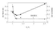
以下のテストファイバ1~5を作製し、第1クラッド径のコア径に対する比D2/D1と曲げ損失及び接続損失との関係を調べる評価試験1を行った。
以下のテストファイバ1~5を作製し、第1クラッド径のコア径に対する比D2/D1と曲げ損失及び接続損失との関係を調べる評価試験1を行った。
-テストファイバ1-
上記実施形態において説明したGI形マルチモード光ファイバを作成し、これをテストファイバ1とした。このGI形マルチモード光ファイバは、コア径D1が50μm、第1クラッド径D2のコア径D1に対する比D2/D1が1.02、第2クラッド厚Tが4.5μm、第3クラッド径D4が125μm、及び被覆層の層厚が62.5μmであった。また、各屈折率n1、n2、n3及びn4は、それぞれ1.472,1.456,1.450,及び1.456であり、第2クラッドの第1クラッドに対する比屈折率差Δ2は0.4%であった。
上記実施形態において説明したGI形マルチモード光ファイバを作成し、これをテストファイバ1とした。このGI形マルチモード光ファイバは、コア径D1が50μm、第1クラッド径D2のコア径D1に対する比D2/D1が1.02、第2クラッド厚Tが4.5μm、第3クラッド径D4が125μm、及び被覆層の層厚が62.5μmであった。また、各屈折率n1、n2、n3及びn4は、それぞれ1.472,1.456,1.450,及び1.456であり、第2クラッドの第1クラッドに対する比屈折率差Δ2は0.4%であった。
この光ファイバを実施例1と同様にして曲げ損失を求めた。また、融着接続器を用いてJIS C6823のカットバック法に準じて測定した接続前及び接続後の光強度から、接続損失を求めた。テストファイバ1の曲げ損失及び接続損失は、それぞれ、0.25dB及び0.40dBであった。
-テストファイバ2-
第1クラッド径D2のコア径D1に対する比D2/D1が1.38であることを除いてテストファイバ1と同一構成のGI形マルチモード光ファイバを作製し、これをテストファイバ2とした。
第1クラッド径D2のコア径D1に対する比D2/D1が1.38であることを除いてテストファイバ1と同一構成のGI形マルチモード光ファイバを作製し、これをテストファイバ2とした。
テストファイバ2の曲げ損失及び接続損失は、それぞれ、0.20dB及び0.12dBであった。
-テストファイバ3-
第1クラッド径D2のコア径D1に対する比D2/D1が1.2であることを除いてテストファイバ1と同一構成のGI形マルチモード光ファイバを作製し、これをテストファイバ3とした。
第1クラッド径D2のコア径D1に対する比D2/D1が1.2であることを除いてテストファイバ1と同一構成のGI形マルチモード光ファイバを作製し、これをテストファイバ3とした。
テストファイバ3の曲げ損失及び接続損失は、それぞれ、0.18dB及び0.09dBであった。
-テストファイバ4-
第1クラッド径D2のコア径D1に対する比D2/D1が1.14であることを除いてテストファイバ1と同一構成のGI形マルチモード光ファイバを作製し、これをテストファイバ4とした。
第1クラッド径D2のコア径D1に対する比D2/D1が1.14であることを除いてテストファイバ1と同一構成のGI形マルチモード光ファイバを作製し、これをテストファイバ4とした。
テストファイバ4の曲げ損失及び接続損失は、それぞれ、0.20dB及び0.10dBであった。
-テストファイバ5-
第1クラッド径D2のコア径D1に対する比D2/D1が2.5であることを除いてテストファイバ1と同一構成のGI形マルチモード光ファイバを作製し、これをテストファイバ5とした。
第1クラッド径D2のコア径D1に対する比D2/D1が2.5であることを除いてテストファイバ1と同一構成のGI形マルチモード光ファイバを作製し、これをテストファイバ5とした。
テストファイバ5曲げ損失及び接続損失は、それぞれ、0.472dB及び0.08dBであった。
<評価試験2>
以下のテストファイバ6~11を作製し、第2クラッド厚Tと曲げ損失との関係を調べる評価試験2を行った。
以下のテストファイバ6~11を作製し、第2クラッド厚Tと曲げ損失との関係を調べる評価試験2を行った。
-テストファイバ6-
上記実施形態において説明したGI形マルチモード光ファイバを作成し、これをテストファイバ6とした。このGI形マルチモード光ファイバは、コア径D1が50μm、第1クラッド径D2のコア径D1に対する比D2/D1が1.38μm、第2クラッド厚Tが8μm、第3クラッド径D4が125μm、及び被覆層の層厚が62.5μmであった。また、各屈折率n1、n2、n3及びn4は、それぞれ1.470,1.456,1.449,及び1.456であり、第2クラッドの第1クラッドに対する比屈折率差Δ2は0.50%であった。
上記実施形態において説明したGI形マルチモード光ファイバを作成し、これをテストファイバ6とした。このGI形マルチモード光ファイバは、コア径D1が50μm、第1クラッド径D2のコア径D1に対する比D2/D1が1.38μm、第2クラッド厚Tが8μm、第3クラッド径D4が125μm、及び被覆層の層厚が62.5μmであった。また、各屈折率n1、n2、n3及びn4は、それぞれ1.470,1.456,1.449,及び1.456であり、第2クラッドの第1クラッドに対する比屈折率差Δ2は0.50%であった。
この光ファイバを実施例1と同様にして曲げ損失を求めたところ、0.20dBであった。
-テストファイバ7-
第2クラッド厚Tが3μmであることを除いてテストファイバ6と同一構成のGI形マルチモード光ファイバを作製し、これをテストファイバ7とした。
第2クラッド厚Tが3μmであることを除いてテストファイバ6と同一構成のGI形マルチモード光ファイバを作製し、これをテストファイバ7とした。
テストファイバ7の曲げ損失は0.32dBであった。
-テストファイバ8-
第2クラッド厚Tが1μmであることを除いてテストファイバ6と同一構成のGI形マルチモード光ファイバを作製し、これをテストファイバ8とした。
第2クラッド厚Tが1μmであることを除いてテストファイバ6と同一構成のGI形マルチモード光ファイバを作製し、これをテストファイバ8とした。
テストファイバ8の曲げ損失は0.472dBであった。
-テストファイバ9-
第2クラッド厚Tが10μmであることを除いてテストファイバ6と同一構成のGI形マルチモード光ファイバを作製し、これをテストファイバ9とした。
第2クラッド厚Tが10μmであることを除いてテストファイバ6と同一構成のGI形マルチモード光ファイバを作製し、これをテストファイバ9とした。
テストファイバ9の曲げ損失は0.32dBであった。
-テストファイバ10-
第2クラッド厚Tが13μmであることを除いてテストファイバ6と同一構成のGI形マルチモード光ファイバを作製し、これをテストファイバ10とした。
第2クラッド厚Tが13μmであることを除いてテストファイバ6と同一構成のGI形マルチモード光ファイバを作製し、これをテストファイバ10とした。
テストファイバ10の曲げ損失は0.09dBであった。
-テストファイバ11-
第2クラッド厚Tが15μmであることを除いてテストファイバ6と同一構成のGI形マルチモード光ファイバを作製し、これをテストファイバ11とした。
第2クラッド厚Tが15μmであることを除いてテストファイバ6と同一構成のGI形マルチモード光ファイバを作製し、これをテストファイバ11とした。
テストファイバ11の曲げ損失は0.05dBであった。
<評価試験3>
以下のテストファイバ12~19を作製し、第2クラッドの第1クラッドに対する比屈折率差Δ2と曲げ損失及び伝送損失との関係を調べる評価試験3を行った。
以下のテストファイバ12~19を作製し、第2クラッドの第1クラッドに対する比屈折率差Δ2と曲げ損失及び伝送損失との関係を調べる評価試験3を行った。
-テストファイバ12-
上記実施形態において説明したGI形マルチモード光ファイバを作成し、これをテストファイバ12とした。このGI形マルチモード光ファイバは、コア径D1が50μm、第1クラッド径D2のコア径D1に対する比D2/D1が1.24、第2クラッド厚Tが6μm、第3クラッド径D4が125μm、及び被覆層の層厚が62.5μmであった。また、各屈折率n1、n2、n3及びn4は、それぞれ1.472,1.456,1.450,及び1.456であり、第2クラッドの第1クラッドに対する比屈折率差Δ2は0.4%であった。
上記実施形態において説明したGI形マルチモード光ファイバを作成し、これをテストファイバ12とした。このGI形マルチモード光ファイバは、コア径D1が50μm、第1クラッド径D2のコア径D1に対する比D2/D1が1.24、第2クラッド厚Tが6μm、第3クラッド径D4が125μm、及び被覆層の層厚が62.5μmであった。また、各屈折率n1、n2、n3及びn4は、それぞれ1.472,1.456,1.450,及び1.456であり、第2クラッドの第1クラッドに対する比屈折率差Δ2は0.4%であった。
この光ファイバを実施例1と同様にして曲げ損失を求めた。また、JIS C6823のOTDR法に準じて伝送損失を求めた。テストファイバ12の曲げ損失及び伝送損失は、それぞれ、0.25dB及び2.20dBであった。
-テストファイバ13-
第2クラッドの屈折率n3が1.452及び第2クラッドの第1クラッドに対する比屈折率差Δ2が0.3であることを除いてテストファイバ12と同一構成のGI形マルチモード光ファイバを作製し、これをテストファイバ13とした。
第2クラッドの屈折率n3が1.452及び第2クラッドの第1クラッドに対する比屈折率差Δ2が0.3であることを除いてテストファイバ12と同一構成のGI形マルチモード光ファイバを作製し、これをテストファイバ13とした。
テストファイバ13の曲げ損失及び伝送損失は、それぞれ、0.31dB及び2.31dBであった。
-テストファイバ14-
第2クラッドの屈折率n3が1.455及び第2クラッドの第1クラッドに対する比屈折率差Δ2が0.1であることを除いてテストファイバ12と同一構成のGI形マルチモード光ファイバを作製し、これをテストファイバ14とした。
第2クラッドの屈折率n3が1.455及び第2クラッドの第1クラッドに対する比屈折率差Δ2が0.1であることを除いてテストファイバ12と同一構成のGI形マルチモード光ファイバを作製し、これをテストファイバ14とした。
テストファイバ14の曲げ損失及び伝送損失は、それぞれ、0.30dB及び2.16dBであった。
-テストファイバ15-
第2クラッドの屈折率n3が1.452及び第2クラッドの第1クラッドに対する比屈折率差Δ2が0.25であることを除いてテストファイバ12と同一構成のGI形マルチモード光ファイバを作製し、これをテストファイバ15とした。
第2クラッドの屈折率n3が1.452及び第2クラッドの第1クラッドに対する比屈折率差Δ2が0.25であることを除いてテストファイバ12と同一構成のGI形マルチモード光ファイバを作製し、これをテストファイバ15とした。
テストファイバ15の曲げ損失及び伝送損失は、それぞれ、0.30dB及び2.22dBであった。
-テストファイバ16-
第2クラッドの屈折率n3が1.451及び第2クラッドの第1クラッドに対する比屈折率差Δ2が0.35であることを除いてテストファイバ12と同一構成のGI形マルチモード光ファイバを作製し、これをテストファイバ16とした。
第2クラッドの屈折率n3が1.451及び第2クラッドの第1クラッドに対する比屈折率差Δ2が0.35であることを除いてテストファイバ12と同一構成のGI形マルチモード光ファイバを作製し、これをテストファイバ16とした。
テストファイバ16の曲げ損失及び伝送損失は、それぞれ、0.30dB及び2.20dBであった。
-テストファイバ17-
第2クラッドの屈折率n3が1.435及び第2クラッドの第1クラッドに対する比屈折率差Δ2が1.45であることを除いてテストファイバ12と同一構成のGI形マルチモード光ファイバを作製し、これをテストファイバ17とした。
第2クラッドの屈折率n3が1.435及び第2クラッドの第1クラッドに対する比屈折率差Δ2が1.45であることを除いてテストファイバ12と同一構成のGI形マルチモード光ファイバを作製し、これをテストファイバ17とした。
テストファイバ17の曲げ損失及び伝送損失は、それぞれ、0.03dB及び2.94dBであった。
-テストファイバ18-
第2クラッドの屈折率n3が1.442及び第2クラッドの第1クラッドに対する比屈折率差Δ2が0.95であることを除いてテストファイバ12と同一構成のGI形マルチモード光ファイバを作製し、これをテストファイバ18とした。
第2クラッドの屈折率n3が1.442及び第2クラッドの第1クラッドに対する比屈折率差Δ2が0.95であることを除いてテストファイバ12と同一構成のGI形マルチモード光ファイバを作製し、これをテストファイバ18とした。
テストファイバ18の曲げ損失及び伝送損失は、それぞれ、0dB及び2.21dBであった。
-テストファイバ19-
第2クラッドの屈折率n3が1.449及び第2クラッドの第1クラッドに対する比屈折率差Δ2が0.5であることを除いてテストファイバ12と同一構成のGI形マルチモード光ファイバを作製し、これをテストファイバ19とした。
第2クラッドの屈折率n3が1.449及び第2クラッドの第1クラッドに対する比屈折率差Δ2が0.5であることを除いてテストファイバ12と同一構成のGI形マルチモード光ファイバを作製し、これをテストファイバ19とした。
テストファイバ19の曲げ損失及び伝送損失は、それぞれ、0.10dB及び2.20dBであった。
<評価試験結果及び考察>
図2によると、第1クラッド径のコア径に対する比D2/D1が1.15~1.25のとき、光ファイバの接続損失を低減させることなく曲げ損失を低減できることが分かる。
図2によると、第1クラッド径のコア径に対する比D2/D1が1.15~1.25のとき、光ファイバの接続損失を低減させることなく曲げ損失を低減できることが分かる。
図3によると、第2クラッド厚Tが7.5μm以上のとき、曲げ損失を低減できることが分かる。
図4によると、第1クラッドに対する第2クラッドの比屈折率差Δ2が0.5~1.5のとき、光ファイバの伝送特性を低下させることなく曲げ損失を低減できることが分かる。
以上説明したように、本発明は許容曲げ径の小さなGI形マルチモード光ファイバについて有用である。
Claims (3)
- 外径が45~65μmのコアと、
上記コアを覆うように設けられた第1クラッドと、
上記第1クラッドを覆うように設けられ該第1クラッドよりも屈折率の低い材料で形成された第2クラッドと、
上記第2クラッドを覆うように設けられ該第2クラッドよりも屈折率の高い材料で形成された第3クラッドと、
を備えたグレーデッドインデックス形マルチモード光ファイバであって、
上記第1クラッドの外径の上記コアの外径に対する比が1.15~1.25であることを特徴とするグレーデッドインデックス形マルチモード光ファイバ。 - 請求項1に記載されたグレーデッドインデックス形マルチモード光ファイバにおいて、
上記第2クラッドの厚さが7.5~15μmであることを特徴とするグレーデッドインデックス形マルチモード光ファイバ。 - 請求項1又は2に記載されたグレーデッドインデックス形マルチモード光ファイバにおいて、
上記第1クラッドに対する上記第2クラッドの比屈折率差が0.5~1.5%であることを特徴とするグレーデッドインデックス形マルチモード光ファイバ。
Priority Applications (1)
| Application Number | Priority Date | Filing Date | Title |
|---|---|---|---|
| US12/920,359 US8554036B2 (en) | 2008-04-16 | 2009-03-13 | Graded index multimode optical fiber |
Applications Claiming Priority (2)
| Application Number | Priority Date | Filing Date | Title |
|---|---|---|---|
| JP2008106744A JP5330729B2 (ja) | 2008-04-16 | 2008-04-16 | グレーデッドインデックス形マルチモード光ファイバ |
| JP2008-106744 | 2008-04-16 |
Publications (1)
| Publication Number | Publication Date |
|---|---|
| WO2009128200A1 true WO2009128200A1 (ja) | 2009-10-22 |
Family
ID=41198911
Family Applications (1)
| Application Number | Title | Priority Date | Filing Date |
|---|---|---|---|
| PCT/JP2009/001141 Ceased WO2009128200A1 (ja) | 2008-04-16 | 2009-03-13 | グレーデッドインデックス形マルチモード光ファイバ |
Country Status (3)
| Country | Link |
|---|---|
| US (1) | US8554036B2 (ja) |
| JP (1) | JP5330729B2 (ja) |
| WO (1) | WO2009128200A1 (ja) |
Cited By (2)
| Publication number | Priority date | Publication date | Assignee | Title |
|---|---|---|---|---|
| CN102998743A (zh) * | 2013-01-05 | 2013-03-27 | 中天科技光纤有限公司 | 适应于长距离通信传输的低损耗单模光纤及其制备方法 |
| CN105759344A (zh) * | 2016-03-23 | 2016-07-13 | 长飞光纤光缆股份有限公司 | 一种抗弯曲多模光纤 |
Families Citing this family (35)
| Publication number | Priority date | Publication date | Assignee | Title |
|---|---|---|---|---|
| WO2009155037A2 (en) | 2008-05-28 | 2009-12-23 | Adc Telecommunications, Inc. | Fiber optic cable |
| FR2932932B1 (fr) | 2008-06-23 | 2010-08-13 | Draka Comteq France Sa | Systeme optique multiplexe en longueur d'ondes avec fibres optiques multimodes |
| FR2933779B1 (fr) | 2008-07-08 | 2010-08-27 | Draka Comteq France | Fibres optiques multimodes |
| FR2940839B1 (fr) | 2009-01-08 | 2012-09-14 | Draka Comteq France | Fibre optique multimodale a gradient d'indice, procedes de caracterisation et de fabrication d'une telle fibre |
| FR2946436B1 (fr) | 2009-06-05 | 2011-12-09 | Draka Comteq France | Fibre optique multimode a tres large bande passante avec une interface coeur-gaine optimisee |
| FR2953029B1 (fr) | 2009-11-25 | 2011-11-18 | Draka Comteq France | Fibre optique multimode a tres large bande passante avec une interface coeur-gaine optimisee |
| FR2953606B1 (fr) | 2009-12-03 | 2012-04-27 | Draka Comteq France | Fibre optique multimode a large bande passante et a faibles pertes par courbure |
| FR2957153B1 (fr) | 2010-03-02 | 2012-08-10 | Draka Comteq France | Fibre optique multimode a large bande passante et a faibles pertes par courbure |
| US9014525B2 (en) | 2009-09-09 | 2015-04-21 | Draka Comteq, B.V. | Trench-assisted multimode optical fiber |
| FR2953030B1 (fr) | 2009-11-25 | 2011-11-18 | Draka Comteq France | Fibre optique multimode a tres large bande passante avec une interface coeur-gaine optimisee |
| FR2953605B1 (fr) | 2009-12-03 | 2011-12-16 | Draka Comteq France | Fibre optique multimode a large bande passante et a faibles pertes par courbure |
| FR2949870B1 (fr) | 2009-09-09 | 2011-12-16 | Draka Compteq France | Fibre optique multimode presentant des pertes en courbure ameliorees |
| FR2950156B1 (fr) | 2009-09-17 | 2011-11-18 | Draka Comteq France | Fibre optique multimode |
| FR2966256B1 (fr) | 2010-10-18 | 2012-11-16 | Draka Comteq France | Fibre optique multimode insensible aux pertes par |
| FR2971061B1 (fr) | 2011-01-31 | 2013-02-08 | Draka Comteq France | Fibre optique a large bande passante et a faibles pertes par courbure |
| DK2482106T5 (da) | 2011-01-31 | 2014-09-22 | Draka Comteq Bv | Multimode-fiber |
| EP2503368A1 (en) | 2011-03-24 | 2012-09-26 | Draka Comteq B.V. | Multimode optical fiber with improved bend resistance |
| EP2506044A1 (en) | 2011-03-29 | 2012-10-03 | Draka Comteq B.V. | Multimode optical fiber |
| EP2518546B1 (en) | 2011-04-27 | 2018-06-20 | Draka Comteq B.V. | High-bandwidth, radiation-resistant multimode optical fiber |
| CN102193142B (zh) * | 2011-06-28 | 2013-06-26 | 长飞光纤光缆有限公司 | 一种抗弯曲大芯径高数值孔径多模光纤 |
| DK2541292T3 (en) | 2011-07-01 | 2014-12-01 | Draka Comteq Bv | A multimode optical fiber |
| US8565567B2 (en) * | 2011-11-23 | 2013-10-22 | Sumitomo Electric Industries, Ltd. | Multi-mode optical fiber |
| US9709731B2 (en) * | 2012-09-05 | 2017-07-18 | Ofs Fitel, Llc | Multiple LP-mode fiber designs for mode-division multiplexing |
| US9671552B2 (en) * | 2012-09-05 | 2017-06-06 | Ofs Fitel, Llc | 9 LP-mode fiber designs for mode-division multiplexing |
| US8768130B1 (en) * | 2013-02-28 | 2014-07-01 | Sumitomo Electric Industries, Ltd. | Multimode optical fiber |
| US9002162B2 (en) * | 2013-03-15 | 2015-04-07 | Ofs Fitel, Llc | Large core multimode optical fibers |
| JP2015212757A (ja) * | 2014-05-02 | 2015-11-26 | 日本電信電話株式会社 | 数モード光ファイバおよび数モード光ファイバの設計方法 |
| JP2016075792A (ja) * | 2014-10-07 | 2016-05-12 | 矢崎総業株式会社 | マルチモード光ファイバ |
| JP6368279B2 (ja) * | 2015-05-26 | 2018-08-01 | 日本電信電話株式会社 | 数モード光ファイバ、及び光ファイバ伝送システム |
| CN105204110B (zh) * | 2015-10-31 | 2018-06-12 | 长飞光纤光缆股份有限公司 | 一种具有较低差分模群时延的少模光纤 |
| JP6312760B2 (ja) * | 2016-08-30 | 2018-04-18 | 株式会社フジクラ | 光ファイバ |
| CN106772788B (zh) * | 2017-02-23 | 2019-12-13 | 中天科技精密材料有限公司 | 一种截止波长位移单模光纤 |
| KR102033405B1 (ko) * | 2017-11-21 | 2019-10-17 | 한국광기술원 | 낮은 굽힘손실을 갖는 광섬유 |
| JP6568979B2 (ja) * | 2018-05-24 | 2019-08-28 | 日本電信電話株式会社 | 数モード光ファイバの設計方法 |
| WO2022187541A1 (en) * | 2021-03-05 | 2022-09-09 | Commscope Technologies Llc | System and method for multicore fiber evaluation using an overfilled launch |
Citations (1)
| Publication number | Priority date | Publication date | Assignee | Title |
|---|---|---|---|---|
| JP2006047719A (ja) * | 2004-08-05 | 2006-02-16 | Fujikura Ltd | 低曲げ損失マルチモードファイバ |
Family Cites Families (21)
| Publication number | Priority date | Publication date | Assignee | Title |
|---|---|---|---|---|
| US4715679A (en) * | 1981-12-07 | 1987-12-29 | Corning Glass Works | Low dispersion, low-loss single-mode optical waveguide |
| JPS59232302A (ja) | 1983-06-15 | 1984-12-27 | Sumitomo Electric Ind Ltd | 光伝送用フアイバ |
| JPS6050502A (ja) * | 1983-08-31 | 1985-03-20 | Furukawa Electric Co Ltd:The | 光フアイバ |
| US4691990A (en) * | 1984-11-13 | 1987-09-08 | American Telephone And Telegraph Company, At&T Bell Laboratories | Optical fiber with depressed index outer cladding |
| US4641917A (en) * | 1985-02-08 | 1987-02-10 | At&T Bell Laboratories | Single mode optical fiber |
| US4852968A (en) * | 1986-08-08 | 1989-08-01 | American Telephone And Telegraph Company, At&T Bell Laboratories | Optical fiber comprising a refractive index trench |
| JPH03211505A (ja) * | 1990-01-17 | 1991-09-17 | Sumitomo Electric Ind Ltd | 光ファイバ |
| US5361319A (en) * | 1992-02-04 | 1994-11-01 | Corning Incorporated | Dispersion compensating devices and systems |
| JPH1082918A (ja) * | 1996-09-09 | 1998-03-31 | Sumitomo Electric Ind Ltd | 光ファイバグレーティング |
| US6535679B2 (en) * | 1997-01-16 | 2003-03-18 | Sumitomo Electric Industries, Ltd. | Optical fiber and method of manufacturing the same |
| US5781673A (en) * | 1997-02-05 | 1998-07-14 | Lucent Technologies Inc. | WDM optical fiber communication system with improved dispersion compensation |
| US6594429B1 (en) * | 2000-10-20 | 2003-07-15 | Lucent Technologies Inc. | Microstructured multimode fiber |
| WO2003022768A2 (de) * | 2001-09-10 | 2003-03-20 | Schott Glas | Glasfaser mit mindestens zwei glasmänteln |
| US6633715B2 (en) * | 2001-12-06 | 2003-10-14 | Fitel Usa Corp. | Optical fiber having negative dispersion, negative dispersion slope and large effective area |
| US7187833B2 (en) * | 2004-04-29 | 2007-03-06 | Corning Incorporated | Low attenuation large effective area optical fiber |
| US6947650B1 (en) * | 2004-05-06 | 2005-09-20 | Luna Energy Llc | Long wavelength, pure silica core single mode fiber and method of forming the same |
| US7646955B2 (en) * | 2004-07-26 | 2010-01-12 | Corning Incorporated | Multimode optical fiber with low differential mode delay |
| JP4444177B2 (ja) * | 2004-08-11 | 2010-03-31 | 古河電気工業株式会社 | 光ファイバ、光ファイバテープおよび光インターコネクションシステム |
| US7421174B2 (en) * | 2006-08-28 | 2008-09-02 | Furakawa Electric North America; Inc. | Multi-wavelength, multimode optical fibers |
| US20080205839A1 (en) * | 2007-02-28 | 2008-08-28 | Scott Robertson Bickham | Large effective area high SBS threshold optical fiber |
| US7680381B1 (en) * | 2008-11-25 | 2010-03-16 | Corning Incorporated | Bend insensitive optical fibers |
-
2008
- 2008-04-16 JP JP2008106744A patent/JP5330729B2/ja active Active
-
2009
- 2009-03-13 US US12/920,359 patent/US8554036B2/en not_active Expired - Fee Related
- 2009-03-13 WO PCT/JP2009/001141 patent/WO2009128200A1/ja not_active Ceased
Patent Citations (1)
| Publication number | Priority date | Publication date | Assignee | Title |
|---|---|---|---|---|
| JP2006047719A (ja) * | 2004-08-05 | 2006-02-16 | Fujikura Ltd | 低曲げ損失マルチモードファイバ |
Non-Patent Citations (1)
| Title |
|---|
| TAKATOSHI KATO ET AL.: "Hacho Taju (WDM) Densoyo Bunsan Shift Fiber", IEICE TECHNICAL REPORT, OCS, HIKARI TSUSHIN SYSTEM, vol. 96, no. 335, 1 November 1996 (1996-11-01), pages 43 - 48 * |
Cited By (3)
| Publication number | Priority date | Publication date | Assignee | Title |
|---|---|---|---|---|
| CN102998743A (zh) * | 2013-01-05 | 2013-03-27 | 中天科技光纤有限公司 | 适应于长距离通信传输的低损耗单模光纤及其制备方法 |
| CN102998743B (zh) * | 2013-01-05 | 2015-04-01 | 中天科技光纤有限公司 | 适应于长距离通信传输的低损耗单模光纤及其制备方法 |
| CN105759344A (zh) * | 2016-03-23 | 2016-07-13 | 长飞光纤光缆股份有限公司 | 一种抗弯曲多模光纤 |
Also Published As
| Publication number | Publication date |
|---|---|
| US8554036B2 (en) | 2013-10-08 |
| JP2009258354A (ja) | 2009-11-05 |
| JP5330729B2 (ja) | 2013-10-30 |
| US20110002590A1 (en) | 2011-01-06 |
Similar Documents
| Publication | Publication Date | Title |
|---|---|---|
| JP5330729B2 (ja) | グレーデッドインデックス形マルチモード光ファイバ | |
| JP6486533B2 (ja) | 光ファイバ | |
| JP5468075B2 (ja) | 少なくとも2つのクラッドを有するマルチモードファイバ | |
| JP5606742B2 (ja) | シングルモード光ファイバ | |
| US8315494B2 (en) | Optical fiber | |
| JP6298893B2 (ja) | 損失低下を示す、台形コアを有するシングルモードファイバ | |
| WO2018063913A1 (en) | Low bend loss single mode optical fiber with bromine up-doped cladding | |
| JP2012203416A (ja) | 曲げ耐性マルチモード光ファイバ | |
| EP2700988A1 (en) | Bending-resistant large core diameter high numerical aperture multimode fiber | |
| WO2009104724A1 (ja) | 光ファイバおよび光ケーブル | |
| KR20040064650A (ko) | 광파이버, 광파이버 리본, 광파이버 어레이, 광학 커넥터및 광학 접속 소자 | |
| EP2420876A4 (en) | Monodic fiber and method of production therefor | |
| JP5476125B2 (ja) | 光ファイバ及びその製造方法 | |
| KR20130036207A (ko) | 굽힘 손실이 적은 광 섬유 | |
| JP2008310328A (ja) | シングルモード光ファイバの曲げ不感性 | |
| EP3268781A1 (en) | Multimode optical fibers | |
| JP2013127608A5 (ja) | 光ファイバ | |
| JP4763106B2 (ja) | 光ファイバ | |
| JP2019152866A (ja) | マルチコアファイバ、光コネクタ、ファンイン/ファンアウトデバイス | |
| WO2011115146A1 (ja) | ホーリーファイバ | |
| CA2565879C (en) | Long wavelength, pure silica core single mode fiber and method of forming the same | |
| JP2019112293A (ja) | 高いシステム光信号対雑音比性能及び非線形性損失による低い劣化を必要とするアプリケーションのための光ファイバ | |
| WO2012128250A1 (ja) | 光ファイバ、光ファイバコードおよび光ファイバケーブル | |
| WO2010035397A1 (ja) | 光ファイバ及びその製造方法 | |
| JPWO2000002074A1 (ja) | 光ファイバ |
Legal Events
| Date | Code | Title | Description |
|---|---|---|---|
| 121 | Ep: the epo has been informed by wipo that ep was designated in this application |
Ref document number: 09732931 Country of ref document: EP Kind code of ref document: A1 |
|
| WWE | Wipo information: entry into national phase |
Ref document number: 12920359 Country of ref document: US |
|
| NENP | Non-entry into the national phase |
Ref country code: DE |
|
| 122 | Ep: pct application non-entry in european phase |
Ref document number: 09732931 Country of ref document: EP Kind code of ref document: A1 |