US8554036B2 - Graded index multimode optical fiber - Google Patents
Graded index multimode optical fiber Download PDFInfo
- Publication number
- US8554036B2 US8554036B2 US12/920,359 US92035909A US8554036B2 US 8554036 B2 US8554036 B2 US 8554036B2 US 92035909 A US92035909 A US 92035909A US 8554036 B2 US8554036 B2 US 8554036B2
- Authority
- US
- United States
- Prior art keywords
- cladding
- refractive index
- optical fiber
- multimode optical
- fiber
- Prior art date
- Legal status (The legal status is an assumption and is not a legal conclusion. Google has not performed a legal analysis and makes no representation as to the accuracy of the status listed.)
- Expired - Fee Related, expires
Links
Images



Classifications
-
- G—PHYSICS
- G02—OPTICS
- G02B—OPTICAL ELEMENTS, SYSTEMS OR APPARATUS
- G02B6/00—Light guides; Structural details of arrangements comprising light guides and other optical elements, e.g. couplings
- G02B6/02—Optical fibres with cladding with or without a coating
- G02B6/036—Optical fibres with cladding with or without a coating core or cladding comprising multiple layers
- G02B6/03616—Optical fibres characterised both by the number of different refractive index layers around the central core segment, i.e. around the innermost high index core layer, and their relative refractive index difference
- G02B6/03638—Optical fibres characterised both by the number of different refractive index layers around the central core segment, i.e. around the innermost high index core layer, and their relative refractive index difference having 3 layers only
- G02B6/0365—Optical fibres characterised both by the number of different refractive index layers around the central core segment, i.e. around the innermost high index core layer, and their relative refractive index difference having 3 layers only arranged - - +
-
- G—PHYSICS
- G02—OPTICS
- G02B—OPTICAL ELEMENTS, SYSTEMS OR APPARATUS
- G02B6/00—Light guides; Structural details of arrangements comprising light guides and other optical elements, e.g. couplings
- G02B6/02—Optical fibres with cladding with or without a coating
- G02B6/028—Optical fibres with cladding with or without a coating with core or cladding having graded refractive index
- G02B6/0288—Multimode fibre, e.g. graded index core for compensating modal dispersion
-
- G—PHYSICS
- G02—OPTICS
- G02B—OPTICAL ELEMENTS, SYSTEMS OR APPARATUS
- G02B6/00—Light guides; Structural details of arrangements comprising light guides and other optical elements, e.g. couplings
- G02B6/02—Optical fibres with cladding with or without a coating
- G02B6/036—Optical fibres with cladding with or without a coating core or cladding comprising multiple layers
- G02B6/03616—Optical fibres characterised both by the number of different refractive index layers around the central core segment, i.e. around the innermost high index core layer, and their relative refractive index difference
- G02B6/03661—Optical fibres characterised both by the number of different refractive index layers around the central core segment, i.e. around the innermost high index core layer, and their relative refractive index difference having 4 layers only
- G02B6/03683—Optical fibres characterised both by the number of different refractive index layers around the central core segment, i.e. around the innermost high index core layer, and their relative refractive index difference having 4 layers only arranged - - + +
Definitions
- the present invention relates to graded index multimode optical fibers.
- Multimode optical fibers through each of which a plurality of modes propagate include step index (SI) fibers and graded index (GI) fibers.
- SI multimode optical fibers each include a core made of, e.g., pure quartz, and each have a uniform refractive index profile.
- GI multimode optical fibers each include a core made of, e.g., quartz doped with germanium (Ge), and each have a refractive index profile called a graded profile along the diameter of the core.
- GI multimode optical fibers are designed to have a graded profile in order to provide uniform propagation delay times of modes, thereby reducing the mode dispersion to a low level.
- graded profiles generally include a square distribution profile.
- PATENT DOCUMENT 1 describes an optical transmission fiber including a GI core having a square refractive index distribution profile, a first cladding surrounding the core and having a thickness of 1/100- 1/20 of the core diameter, a second cladding surrounding the first cladding and having a lower refractive index than the first cladding, and a third cladding surrounding the second cladding and having a lower refractive index than the second cladding.
- PATENT DOCUMENT 2 describes a GI multimode optical fiber including a core having an ⁇ -th power refractive index profile and a cladding surrounding the core, and configured so that an outer peripheral portion of the cladding forms a depressed region. Such a depressed region has a lower refractive index than an inner peripheral portion of the cladding, and has a multiple-step-like refractive index profile in which the refractive index increases toward the outer periphery of the cladding. PATENT DOCUMENT 2 further describes that such a configuration can provide excellent bending loss characteristics of a GI multimode optical fiber.
- PATENT DOCUMENT 1 Japanese Patent Publication No. S59-232302
- PATENT DOCUMENT 2 Japanese Patent Publication No. 2006-47719
- a graded index multimode optical fiber of the present invention includes: a core having an outside diameter of 45-65 ⁇ m; a first cladding surrounding the core; a second cladding surrounding the first cladding and made of a material having a lower refractive index than the first cladding; and a third cladding surrounding the second cladding and made of a material having a higher refractive index than the second cladding.
- the ratio of an outside diameter of the first cladding to the outside diameter of the core is 1.15-1.25.
- the second cladding may have a thickness of 7.5-15 ⁇ m.
- the relative refractive index difference of the second cladding with respect to the first cladding may be 0.5-1.5%.
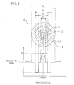
- FIG. 1 is a schematic view schematically illustrating a cross-sectional view of a GI multimode optical fiber according to this embodiment, and the refractive index profile corresponding to the cross-sectional view together.
- FIG. 2 is a graph illustrating the relationships between the ratio of the first cladding diameter to the core diameter and the bending loss and between the above ratio and the splice loss.
- FIG. 3 is a graph illustrating the relationship between the second cladding thickness and the bending loss.
- FIG. 4 is a graph illustrating the relationships between the relative refractive index difference of the second cladding with respect to the first cladding and the bending loss and between the above relative refractive index difference and the transmission loss.
- a GI multimode optical fiber 10 is used for, e.g., communications cables and wiring in devices.
- FIG. 1 illustrates a cross-sectional view of the GI multimode optical fiber 10 according to this embodiment, and the refractive index profile corresponding to the cross-sectional view together.
- the GI multimode optical fiber 10 includes a core 11 at the center of the fiber, a first cladding 12 surrounding the core 11 , a second cladding 13 surrounding the first cladding 12 , a third cladding 14 surrounding the second cladding 13 , and a coating layer (not shown) surrounding the third cladding 14 .
- the GI multimode optical fiber 10 has a diameter of, e.g., 125 ⁇ m.
- the core 11 is made of, e.g., quartz doped with germanium, etc.
- the refractive index profile of the core 11 corresponds to a GI profile in which the refractive index increases toward the center of the core 11 while decreasing toward the outer periphery thereof.
- the refractive index profile corresponds to a square refractive index distribution profile designed to uniform propagation delay times of modes. Such a refractive index profile is formed by increasing the doping concentration of germanium toward the center of the core 11 and decreasing the dose of germanium toward the outer periphery thereof.
- the relative refractive index difference ⁇ 1 of the highest refractive index n 1 (i.e., the refractive index of the core center) with respect to the lowest refractive index n 2 (i.e., the refractive index of the outer periphery of the core 11 ) is, for example, 1.0%.
- the core 11 has an outside diameter D 1 of, e.g., 45-65 ⁇ m.
- the core diameter D 1 is preferably equal to, e.g., the outside diameter of the core of a multimode optical fiber defined as SGI-50/125 in the JIS C6832 standard (i.e., 50 ⁇ m), or the core diameter of an optical fiber conforming to the international electrotechnical commission (IEC) standard (i.e., 62.5 ⁇ m) in terms of consistency with already-existing optical fibers or any other optical elements.
- IEC international electrotechnical commission
- the first cladding 12 is made of, e.g., pure quartz.
- the refractive index n 2 of the first cladding 12 is, for example, 1.456.
- the outside diameter D 2 of the first cladding 12 is, for example, 50-80 ⁇ m.
- the ratio D 2 /D 1 of the first cladding diameter D 2 to the core diameter D 1 is 1.15-1.25 and preferably 1.17-1.23.
- the second cladding 13 is made of, e.g., quartz doped with fluorine, boron, etc.
- the thickness T of the second cladding 13 is preferably greater than or equal to 7.5 ⁇ m and more preferably greater than or equal to 10 ⁇ m in order to reduce the bending loss.
- the thickness T of the second cladding 13 is preferably less than or equal to 15 ⁇ m in terms of the design of the diameter of the entire GI multimode optical fiber 10 .
- the thickness T of the second cladding 13 is preferably 7.5-15 ⁇ m and more preferably 10-15 ⁇ m.
- the refractive index n 3 of the second cladding 13 is lower than the refractive index n 2 of the first cladding 12 .
- the refractive index n 3 of the second cladding 13 is, for example, 1.434-1.449.
- the relative refractive index difference ⁇ 2 of the second cladding 13 with respect to the first cladding 12 is preferably 0.5-1.5% and more preferably 0.7-1.4% in order to reduce the bending loss without increasing the transmission loss.
- the third cladding 14 is made of, for example, pure quartz.
- the refractive index n 4 of the third cladding 14 is, for example, 1.456.
- the outside diameter D 4 of the third cladding 14 is, for example, 110-140 ⁇ m.
- the outside diameter D 4 of the third cladding 14 is preferably equal to, e.g., the outside diameter of the cladding of a multimode optical fiber defined as SGI-50/125 in the JIS C6832 standard (i.e., 125 ⁇ m) in terms of consistency with already-existing optical fibers or any other optical elements.
- the coating layer is made of, e.g., polyamide resin, UV curable resin, or silicone resin.
- the coating layer has a thickness of, e.g., 60-400 ⁇ m.
- the GI multimode optical fiber 10 can be fabricated by the following conventional method: a preform having a refractive index profile proportional to the refractive index profile of the optical fiber is produced by, e.g., chemical vapor deposition (CVD), outside vapor phase deposition (OVD), vapor-phase axial deposition (VAD), or a rod-in-tube technique; the surface of the optical fiber obtained by heating and drawing the preform is protected by the coating layer; and a screening test is performed on the protected optical fiber in order to increase the mechanical strength of the optical fiber.
- CVD chemical vapor deposition
- OLED outside vapor phase deposition
- VAD vapor-phase axial deposition
- FTTH fiber to the home
- Methods for reducing the allowable bend diameter of an optical fiber include a method in which the core refractive index is increased. However, this method causes the problem of a reduction in transmission band characteristics and the problem of an increase in transmission loss. The method further causes the problem of an increase in splice loss with a GI optical fiber for general purpose use.
- the ratio D 2 /D 1 of the first cladding diameter D 2 to the core diameter D 1 of the GI multimode optical fiber 10 is 1.15-1.25, and thus, even when the optical fiber 10 is bent to a radius of curvature of approximately 5 mm or approximately 10 mm by external forces, light can be transmitted with a reduction in the bending loss.
- GI multimode optical fibers configured as described above were fabricated as first and second examples described below. Table 1 also illustrates the configurations and results of the fibers.
- a GI multimode optical fiber described in the embodiment was fabricated.
- the core diameter D 1 was 47.5 ⁇ m
- the ratio D 2 /D 1 of the first cladding diameter D 2 to the core diameter D 1 was 1.21
- the second cladding thickness T was 7.65 ⁇ m
- the third cladding diameter D 4 was 125 ⁇ m
- the coating layer thickness was 62.5 ⁇ m.
- the refractive indices n 1 , n 2 , n 3 , and n 4 were 1.472, 1.456, 1.442, and 1.456, respectively
- the relative refractive index difference ⁇ 2 of the second cladding with respect to the first cladding was 0.95%.
- the optical fiber was wrapped ten turns around a mandrel having a radius of 5 mm. Tests for light intensity were preformed before and after the wrapping of the optical fiber in conformity with the cutback method in the JIS C6823 standard. When the bending loss was determined based on the test results, the bending loss was 0 dB.
- a GI multimode optical fiber described in the embodiment was fabricated.
- the core diameter D 1 was 49.3 ⁇ m
- the ratio D 2 /D 1 of the first cladding diameter D 2 to the core diameter D 1 was 1.16
- the second cladding thickness T was 10.1 ⁇ m
- the third cladding diameter D 4 was 125 ⁇ m
- the coating layer thickness was 62.5 ⁇ m.
- the refractive indices n 1 , n 2 , n 3 , and n 4 were 1.472, 1.456, 1.435, and 1.456, respectively, and the relative refractive index difference ⁇ 2 of the second cladding with respect to the first cladding was 1.42%.
- the bending loss of the second example was determined similarly to that of the first example, the bending loss of the second example was 0.03 dB.
- the results of the first and second examples show that when the ratio D 2 /D 1 of the first cladding diameter D 2 to the core diameter D 1 is 1.15-1.25, the second cladding thickness T is 7.5-15 ⁇ m, and the relative refractive index difference ⁇ 2 of the first cladding with respect to the second cladding is 0.5-1.5%, neither of the band characteristics and splice characteristics of a GI multimode optical fiber having a small allowable bend diameter is reduced.
- First through fifth test fibers described below were fabricated, and the first evaluation test was performed in order to examine the relationships between the ratio D 2 /D 1 of the first cladding diameter D 2 to the core diameter D 1 and the bending loss and between the above ratio and the splice loss.
- a GI multimode optical fiber described in the embodiment was fabricated.
- the core diameter D 1 was 50 ⁇ m
- the ratio D 2 /D 1 of the first cladding diameter D 2 to the core diameter D 1 was 1.02
- the second cladding thickness T was 4.5 ⁇ m
- the third cladding diameter D 4 was 125 ⁇ m
- the coating layer thickness was 62.5 ⁇ m.
- the refractive indices n 1 , n 2 , n 3 , and n 4 were 1.472, 1.456, 1.450, and 1.456, respectively
- the relative refractive index difference ⁇ 2 of the second cladding with respect to the first cladding was 0.4%.
- the bending loss of the optical fiber was determined similarly to that of the first example. Furthermore, the splice loss was determined based on the light intensities before and after splicing, which were measured in conformity with the cutback method in the JIS C6823 standard by using a fusion splicer. The bending loss and splice loss of the first test fiber were 0.25 dB and 0.40 dB, respectively.
- a GI multimode optical fiber was fabricated with the same configuration as the first test fiber except that the ratio D 2 /D 1 of the first cladding diameter D 2 to the core diameter D 1 was 1.38.
- the bending loss and splice loss of the second test fiber were 0.20 dB and 0.12 dB, respectively.
- a GI multimode optical fiber was fabricated with the same configuration as the first test fiber except that the ratio D 2 /D 1 of the first cladding diameter D 2 to the core diameter D 1 was 1.2.
- the bending loss and splice loss of the third test fiber were 0.18 dB and 0.09 dB, respectively.
- a GI multimode optical fiber was fabricated with the same configuration as the first test fiber except that the ratio D 2 /D 1 of the first cladding diameter D 2 to the core diameter D 1 was 1.14.
- the bending loss and splice loss of the fourth test fiber were 0.20 dB and 0.10 dB, respectively.
- a GI multimode optical fiber was fabricated with the same configuration as the first test fiber except that the ratio D 2 /D 1 of the first cladding diameter D 2 to the core diameter D 1 was 2.5.
- the bending loss and splice loss of the fifth test fiber were 0.472 dB and 0.08 dB, respectively.
- a GI multimode optical fiber described in the embodiment was fabricated.
- the core diameter D 1 was 50 ⁇ m
- the ratio D 2 /D 1 of the first cladding diameter D 2 to the core diameter D 1 was 1.38
- the second cladding thickness T was 8 ⁇ m
- the third cladding diameter D 4 was 125 ⁇ m
- the coating layer thickness was 62.5 ⁇ m.
- the refractive indices n 1 , n 2 , n 3 , and n 4 were 1.470, 1.456, 1.449, and 1.456, respectively
- the relative refractive index difference ⁇ 2 of the second cladding with respect to the first cladding was 0.50%.
- the bending loss of the optical fiber was determined similarly to that of the first example, the bending loss was 0.20 dB.
- a GI multimode optical fiber was fabricated with the same configuration as the sixth test fiber except that the second cladding thickness T was 3 ⁇ m.
- the bending loss of the seventh test fiber was 0.32 dB.
- a GI multimode optical fiber was fabricated with the same configuration as the sixth test fiber except that the second cladding thickness T was 1 ⁇ m.
- the bending loss of the eighth test fiber was 0.472 dB.
- a GI multimode optical fiber was fabricated with the same configuration as the sixth test fiber except that the second cladding thickness T was 10 ⁇ m.
- the bending loss of the ninth test fiber was 0.32 dB.
- a GI multimode optical fiber was fabricated with the same configuration as the sixth test fiber except that the second cladding thickness T was 13 ⁇ m.
- the bending loss of the tenth test fiber was 0.09 dB.
- a GI multimode optical fiber was fabricated with the same configuration as the sixth test fiber except that the second cladding thickness T was 15 ⁇ m.
- the bending loss of the eleventh test fiber was 0.05 dB.
- Twelfth through nineteenth test fibers described below were fabricated, and the third evaluation test was performed in order to examine the relationships between the relative refractive index difference ⁇ 2 of the second cladding with respect to the first cladding and the bending loss and between the above relative refractive index difference and the transmission loss.
- a GI multimode optical fiber described in the embodiment was fabricated.
- the core diameter D 1 was 50 the ratio D 2 /D 1 of the first cladding diameter D 2 to the core diameter D 1 was 1.24
- the second cladding thickness T was 6
- the third cladding diameter D 4 was 125 ⁇ m
- the coating layer thickness was 62.5 ⁇ m.
- the refractive indices n 1 , n 2 , n 3 , and n 4 were 1.472, 1.456, 1.450, and 1.456, respectively, and the relative refractive index difference ⁇ 2 of the second cladding with respect to the first cladding was 0.4%.
- the bending loss of the optical fiber was determined similarly to that of the first example. Furthermore, the transmission loss was determined in conformity with the OTDR method in the JIS C6823 standard. The bending loss and transmission loss of the twelfth test fiber were 0.25 dB and 2.20 dB, respectively.
- a GI multimode optical fiber was fabricated with the same configuration as the twelfth test fiber except that the refractive index n 3 of the second cladding was 1.452 and the relative refractive index difference ⁇ 2 of the second cladding with respect to the first cladding was 0.3.
- the bending loss and transmission loss of the thirteenth test fiber were 0.31 dB and 2.31 dB, respectively.
- a GI multimode optical fiber was fabricated with the same configuration as the twelfth test fiber except that the refractive index n 3 of the second cladding was 1.455 and the relative refractive index difference ⁇ 2 of the second cladding with respect to the first cladding was 0.1.
- the bending loss and transmission loss of the fourteenth test fiber were 0.30 dB and 2.16 dB, respectively.
- a GI multimode optical fiber was fabricated with the same configuration as the twelfth test fiber except that the refractive index n 3 of the second cladding was 1.452 and the relative refractive index difference ⁇ 2 of the second cladding with respect to the first cladding was 0.25.
- the bending loss and transmission loss of the fourteenth test fiber were 0.30 dB and 2.22 dB, respectively.
- a GI multimode optical fiber was fabricated with the same configuration as the twelfth test fiber except that the refractive index n 3 of the second cladding was 1.451 and the relative refractive index difference ⁇ 2 of the second cladding with respect to the first cladding was 0.35.
- the bending loss and transmission loss of the sixteenth test fiber were 0.30 dB and 2.20 dB, respectively.
- a GI multimode optical fiber was fabricated with the same configuration as the twelfth test fiber except that the refractive index n 3 of the second cladding was 1.435 and the relative refractive index difference ⁇ 2 of the second cladding with respect to the first cladding was 1.45.
- the bending loss and transmission loss of the seventeenth test fiber were 0.03 dB and 2.94 dB, respectively.
- a GI multimode optical fiber was fabricated with the same configuration as the twelfth test fiber except that the refractive index n 3 of the second cladding was 1.442 and the relative refractive index difference ⁇ 2 of the second cladding with respect to the first cladding was 0.95.
- the bending loss and transmission loss of the eighteenth test fiber were 0 dB and 2.21 dB, respectively.
- a GI multimode optical fiber was fabricated with the same configuration as the twelfth test fiber except that the refractive index n 3 of the second cladding was 1.449 and the relative refractive index difference ⁇ 2 of the second cladding with respect to the first cladding was 0.5.
- the bending loss and transmission loss of the nineteenth test fiber were 0.10 dB and 2.20 dB, respectively.
- FIG. 2 shows that when the ratio D 2 /D 1 of the first cladding diameter D 2 to the core diameter D 1 is 1.15-1.25, the bending loss of the optical fiber can be reduced without reducing the splice loss thereof.
- FIG. 3 shows that when the second cladding thickness T is greater than or equal to 7.5 ⁇ m, the bending loss can be reduced.
- FIG. 4 shows that when the relative refractive index difference ⁇ 2 of the second cladding with respect to the first cladding is 0.5-1.5, the bending loss of the optical fiber can be reduced without reducing the transmission characteristics thereof.
- the present invention is useful for GI multimode optical fibers each having a small allowable bend diameter.
Landscapes
- Physics & Mathematics (AREA)
- General Physics & Mathematics (AREA)
- Optics & Photonics (AREA)
- Chemical & Material Sciences (AREA)
- Dispersion Chemistry (AREA)
- Optical Fibers, Optical Fiber Cores, And Optical Fiber Bundles (AREA)
Applications Claiming Priority (3)
| Application Number | Priority Date | Filing Date | Title |
|---|---|---|---|
| JP2008106744A JP5330729B2 (ja) | 2008-04-16 | 2008-04-16 | グレーデッドインデックス形マルチモード光ファイバ |
| JP2008-106744 | 2008-04-16 | ||
| PCT/JP2009/001141 WO2009128200A1 (ja) | 2008-04-16 | 2009-03-13 | グレーデッドインデックス形マルチモード光ファイバ |
Publications (2)
| Publication Number | Publication Date |
|---|---|
| US20110002590A1 US20110002590A1 (en) | 2011-01-06 |
| US8554036B2 true US8554036B2 (en) | 2013-10-08 |
Family
ID=41198911
Family Applications (1)
| Application Number | Title | Priority Date | Filing Date |
|---|---|---|---|
| US12/920,359 Expired - Fee Related US8554036B2 (en) | 2008-04-16 | 2009-03-13 | Graded index multimode optical fiber |
Country Status (3)
| Country | Link |
|---|---|
| US (1) | US8554036B2 (ja) |
| JP (1) | JP5330729B2 (ja) |
| WO (1) | WO2009128200A1 (ja) |
Cited By (1)
| Publication number | Priority date | Publication date | Assignee | Title |
|---|---|---|---|---|
| US10670812B2 (en) * | 2016-08-30 | 2020-06-02 | Fujikura Ltd. | Optical fiber |
Families Citing this family (36)
| Publication number | Priority date | Publication date | Assignee | Title |
|---|---|---|---|---|
| WO2009155037A2 (en) | 2008-05-28 | 2009-12-23 | Adc Telecommunications, Inc. | Fiber optic cable |
| FR2932932B1 (fr) | 2008-06-23 | 2010-08-13 | Draka Comteq France Sa | Systeme optique multiplexe en longueur d'ondes avec fibres optiques multimodes |
| FR2933779B1 (fr) | 2008-07-08 | 2010-08-27 | Draka Comteq France | Fibres optiques multimodes |
| FR2940839B1 (fr) | 2009-01-08 | 2012-09-14 | Draka Comteq France | Fibre optique multimodale a gradient d'indice, procedes de caracterisation et de fabrication d'une telle fibre |
| FR2946436B1 (fr) | 2009-06-05 | 2011-12-09 | Draka Comteq France | Fibre optique multimode a tres large bande passante avec une interface coeur-gaine optimisee |
| FR2953029B1 (fr) | 2009-11-25 | 2011-11-18 | Draka Comteq France | Fibre optique multimode a tres large bande passante avec une interface coeur-gaine optimisee |
| FR2953606B1 (fr) | 2009-12-03 | 2012-04-27 | Draka Comteq France | Fibre optique multimode a large bande passante et a faibles pertes par courbure |
| FR2957153B1 (fr) | 2010-03-02 | 2012-08-10 | Draka Comteq France | Fibre optique multimode a large bande passante et a faibles pertes par courbure |
| US9014525B2 (en) | 2009-09-09 | 2015-04-21 | Draka Comteq, B.V. | Trench-assisted multimode optical fiber |
| FR2953030B1 (fr) | 2009-11-25 | 2011-11-18 | Draka Comteq France | Fibre optique multimode a tres large bande passante avec une interface coeur-gaine optimisee |
| FR2953605B1 (fr) | 2009-12-03 | 2011-12-16 | Draka Comteq France | Fibre optique multimode a large bande passante et a faibles pertes par courbure |
| FR2949870B1 (fr) | 2009-09-09 | 2011-12-16 | Draka Compteq France | Fibre optique multimode presentant des pertes en courbure ameliorees |
| FR2950156B1 (fr) | 2009-09-17 | 2011-11-18 | Draka Comteq France | Fibre optique multimode |
| FR2966256B1 (fr) | 2010-10-18 | 2012-11-16 | Draka Comteq France | Fibre optique multimode insensible aux pertes par |
| FR2971061B1 (fr) | 2011-01-31 | 2013-02-08 | Draka Comteq France | Fibre optique a large bande passante et a faibles pertes par courbure |
| DK2482106T5 (da) | 2011-01-31 | 2014-09-22 | Draka Comteq Bv | Multimode-fiber |
| EP2503368A1 (en) | 2011-03-24 | 2012-09-26 | Draka Comteq B.V. | Multimode optical fiber with improved bend resistance |
| EP2506044A1 (en) | 2011-03-29 | 2012-10-03 | Draka Comteq B.V. | Multimode optical fiber |
| EP2518546B1 (en) | 2011-04-27 | 2018-06-20 | Draka Comteq B.V. | High-bandwidth, radiation-resistant multimode optical fiber |
| CN102193142B (zh) * | 2011-06-28 | 2013-06-26 | 长飞光纤光缆有限公司 | 一种抗弯曲大芯径高数值孔径多模光纤 |
| DK2541292T3 (en) | 2011-07-01 | 2014-12-01 | Draka Comteq Bv | A multimode optical fiber |
| US8565567B2 (en) * | 2011-11-23 | 2013-10-22 | Sumitomo Electric Industries, Ltd. | Multi-mode optical fiber |
| US9709731B2 (en) * | 2012-09-05 | 2017-07-18 | Ofs Fitel, Llc | Multiple LP-mode fiber designs for mode-division multiplexing |
| US9671552B2 (en) * | 2012-09-05 | 2017-06-06 | Ofs Fitel, Llc | 9 LP-mode fiber designs for mode-division multiplexing |
| CN102998743B (zh) * | 2013-01-05 | 2015-04-01 | 中天科技光纤有限公司 | 适应于长距离通信传输的低损耗单模光纤及其制备方法 |
| US8768130B1 (en) * | 2013-02-28 | 2014-07-01 | Sumitomo Electric Industries, Ltd. | Multimode optical fiber |
| US9002162B2 (en) * | 2013-03-15 | 2015-04-07 | Ofs Fitel, Llc | Large core multimode optical fibers |
| JP2015212757A (ja) * | 2014-05-02 | 2015-11-26 | 日本電信電話株式会社 | 数モード光ファイバおよび数モード光ファイバの設計方法 |
| JP2016075792A (ja) * | 2014-10-07 | 2016-05-12 | 矢崎総業株式会社 | マルチモード光ファイバ |
| JP6368279B2 (ja) * | 2015-05-26 | 2018-08-01 | 日本電信電話株式会社 | 数モード光ファイバ、及び光ファイバ伝送システム |
| CN105204110B (zh) * | 2015-10-31 | 2018-06-12 | 长飞光纤光缆股份有限公司 | 一种具有较低差分模群时延的少模光纤 |
| CN105759344B (zh) * | 2016-03-23 | 2018-11-30 | 长飞光纤光缆股份有限公司 | 一种抗弯曲多模光纤 |
| CN106772788B (zh) * | 2017-02-23 | 2019-12-13 | 中天科技精密材料有限公司 | 一种截止波长位移单模光纤 |
| KR102033405B1 (ko) * | 2017-11-21 | 2019-10-17 | 한국광기술원 | 낮은 굽힘손실을 갖는 광섬유 |
| JP6568979B2 (ja) * | 2018-05-24 | 2019-08-28 | 日本電信電話株式会社 | 数モード光ファイバの設計方法 |
| WO2022187541A1 (en) * | 2021-03-05 | 2022-09-09 | Commscope Technologies Llc | System and method for multicore fiber evaluation using an overfilled launch |
Citations (20)
| Publication number | Priority date | Publication date | Assignee | Title |
|---|---|---|---|---|
| JPS59232302A (ja) | 1983-06-15 | 1984-12-27 | Sumitomo Electric Ind Ltd | 光伝送用フアイバ |
| US4641917A (en) * | 1985-02-08 | 1987-02-10 | At&T Bell Laboratories | Single mode optical fiber |
| US4691990A (en) * | 1984-11-13 | 1987-09-08 | American Telephone And Telegraph Company, At&T Bell Laboratories | Optical fiber with depressed index outer cladding |
| US4715679A (en) * | 1981-12-07 | 1987-12-29 | Corning Glass Works | Low dispersion, low-loss single-mode optical waveguide |
| US4852968A (en) * | 1986-08-08 | 1989-08-01 | American Telephone And Telegraph Company, At&T Bell Laboratories | Optical fiber comprising a refractive index trench |
| US5361319A (en) * | 1992-02-04 | 1994-11-01 | Corning Incorporated | Dispersion compensating devices and systems |
| US5781673A (en) * | 1997-02-05 | 1998-07-14 | Lucent Technologies Inc. | WDM optical fiber communication system with improved dispersion compensation |
| US5883990A (en) * | 1996-09-09 | 1999-03-16 | Sumitomo Electric Industries, Ltd. | Low transmission loss optical fiber having a grating |
| US20010043782A1 (en) * | 1997-01-16 | 2001-11-22 | Yoshio Yokoyama | Optical fiber and method of manufacturing the same |
| US20030113084A1 (en) * | 2001-12-06 | 2003-06-19 | Knudsen Stig Nissen | Optical fiber having negative dispersion, negative dispersion slope and large effective area |
| US6594429B1 (en) * | 2000-10-20 | 2003-07-15 | Lucent Technologies Inc. | Microstructured multimode fiber |
| US20040252961A1 (en) * | 2001-09-10 | 2004-12-16 | Ulrich Peuchert | Glass fibre with at least two glass layers |
| US6947650B1 (en) * | 2004-05-06 | 2005-09-20 | Luna Energy Llc | Long wavelength, pure silica core single mode fiber and method of forming the same |
| US20060034575A1 (en) * | 2004-08-11 | 2006-02-16 | The Furukawa Electric Co., Ltd. | Optical fiber, optical fiber ribbon, and optical interconnection system |
| JP2006047719A (ja) | 2004-08-05 | 2006-02-16 | Fujikura Ltd | 低曲げ損失マルチモードファイバ |
| US20070053642A1 (en) * | 2004-04-29 | 2007-03-08 | Mishra Snigdharaj K | Low attenuation large effective area optical fiber |
| US20080050075A1 (en) * | 2006-08-28 | 2008-02-28 | James William Fleming | Multi-wavelength, multimode optical fibers |
| US20090052851A1 (en) * | 2004-07-26 | 2009-02-26 | Photonium Oy | Multimode optical fiber with low differential mode delay |
| US20090060436A1 (en) * | 2007-02-28 | 2009-03-05 | Scott Robertson Bickham | Large effective area high SBS threshold optical fiber |
| US7680381B1 (en) * | 2008-11-25 | 2010-03-16 | Corning Incorporated | Bend insensitive optical fibers |
Family Cites Families (2)
| Publication number | Priority date | Publication date | Assignee | Title |
|---|---|---|---|---|
| JPS6050502A (ja) * | 1983-08-31 | 1985-03-20 | Furukawa Electric Co Ltd:The | 光フアイバ |
| JPH03211505A (ja) * | 1990-01-17 | 1991-09-17 | Sumitomo Electric Ind Ltd | 光ファイバ |
-
2008
- 2008-04-16 JP JP2008106744A patent/JP5330729B2/ja active Active
-
2009
- 2009-03-13 US US12/920,359 patent/US8554036B2/en not_active Expired - Fee Related
- 2009-03-13 WO PCT/JP2009/001141 patent/WO2009128200A1/ja not_active Ceased
Patent Citations (26)
| Publication number | Priority date | Publication date | Assignee | Title |
|---|---|---|---|---|
| US4715679A (en) * | 1981-12-07 | 1987-12-29 | Corning Glass Works | Low dispersion, low-loss single-mode optical waveguide |
| JPS59232302A (ja) | 1983-06-15 | 1984-12-27 | Sumitomo Electric Ind Ltd | 光伝送用フアイバ |
| US4715695A (en) * | 1983-06-15 | 1987-12-29 | Sumitomo Electric Industries, Ltd. | Fiber for optical transmission |
| US4691990A (en) * | 1984-11-13 | 1987-09-08 | American Telephone And Telegraph Company, At&T Bell Laboratories | Optical fiber with depressed index outer cladding |
| US4641917A (en) * | 1985-02-08 | 1987-02-10 | At&T Bell Laboratories | Single mode optical fiber |
| US4852968A (en) * | 1986-08-08 | 1989-08-01 | American Telephone And Telegraph Company, At&T Bell Laboratories | Optical fiber comprising a refractive index trench |
| US5361319A (en) * | 1992-02-04 | 1994-11-01 | Corning Incorporated | Dispersion compensating devices and systems |
| US5883990A (en) * | 1996-09-09 | 1999-03-16 | Sumitomo Electric Industries, Ltd. | Low transmission loss optical fiber having a grating |
| US20010043782A1 (en) * | 1997-01-16 | 2001-11-22 | Yoshio Yokoyama | Optical fiber and method of manufacturing the same |
| US6535679B2 (en) * | 1997-01-16 | 2003-03-18 | Sumitomo Electric Industries, Ltd. | Optical fiber and method of manufacturing the same |
| US5781673A (en) * | 1997-02-05 | 1998-07-14 | Lucent Technologies Inc. | WDM optical fiber communication system with improved dispersion compensation |
| US6594429B1 (en) * | 2000-10-20 | 2003-07-15 | Lucent Technologies Inc. | Microstructured multimode fiber |
| US20040252961A1 (en) * | 2001-09-10 | 2004-12-16 | Ulrich Peuchert | Glass fibre with at least two glass layers |
| US20030113084A1 (en) * | 2001-12-06 | 2003-06-19 | Knudsen Stig Nissen | Optical fiber having negative dispersion, negative dispersion slope and large effective area |
| US20070053642A1 (en) * | 2004-04-29 | 2007-03-08 | Mishra Snigdharaj K | Low attenuation large effective area optical fiber |
| US7254305B2 (en) * | 2004-04-29 | 2007-08-07 | Corning Incorporated | Low attenuation large effective area optical fiber |
| US6947650B1 (en) * | 2004-05-06 | 2005-09-20 | Luna Energy Llc | Long wavelength, pure silica core single mode fiber and method of forming the same |
| US20090052851A1 (en) * | 2004-07-26 | 2009-02-26 | Photonium Oy | Multimode optical fiber with low differential mode delay |
| JP2006047719A (ja) | 2004-08-05 | 2006-02-16 | Fujikura Ltd | 低曲げ損失マルチモードファイバ |
| US20060034575A1 (en) * | 2004-08-11 | 2006-02-16 | The Furukawa Electric Co., Ltd. | Optical fiber, optical fiber ribbon, and optical interconnection system |
| US7295741B2 (en) * | 2004-08-11 | 2007-11-13 | The Furukawa Electric Co., Ltd. | Optical fiber, optical fiber ribbon, and optical interconnection system |
| US20080050075A1 (en) * | 2006-08-28 | 2008-02-28 | James William Fleming | Multi-wavelength, multimode optical fibers |
| US7421174B2 (en) * | 2006-08-28 | 2008-09-02 | Furakawa Electric North America; Inc. | Multi-wavelength, multimode optical fibers |
| US20090060436A1 (en) * | 2007-02-28 | 2009-03-05 | Scott Robertson Bickham | Large effective area high SBS threshold optical fiber |
| US7773846B2 (en) * | 2007-02-28 | 2010-08-10 | Corning Incorporated | Large effective area high SBS threshold optical fiber |
| US7680381B1 (en) * | 2008-11-25 | 2010-03-16 | Corning Incorporated | Bend insensitive optical fibers |
Non-Patent Citations (5)
| Title |
|---|
| Form PCT/ISA/237 for International Application No. PCT/JP2009/001141 dated May 12, 2009. |
| International Search Report for corresponding International Application No. PCT/JP2009/001141 mailed May 12, 2009. |
| Nunome et al., Institute of Electronics, Information, and Communication Engineers; "Chromatic Dispersion Characteristics of Trench Type Optical Fiber", Mar. 20, 2007, p. 350, with partial English translation. |
| Nunome et al., Institute of Electronics, Information, and Communication Engineers; "Splice Characteristics of Trench-Assisted Bend-Insensitive Fiber", Sep. 10, 2007, p. 207, with partial English translation. |
| Takatoshi Kato et al., "Depression Shifted Fiber for WDM Transmission", Technical Report of IEICE, OCS96-58, OPE96-106, LQE96-109, Nov. 1996 and partial English translation. |
Cited By (1)
| Publication number | Priority date | Publication date | Assignee | Title |
|---|---|---|---|---|
| US10670812B2 (en) * | 2016-08-30 | 2020-06-02 | Fujikura Ltd. | Optical fiber |
Also Published As
| Publication number | Publication date |
|---|---|
| WO2009128200A1 (ja) | 2009-10-22 |
| JP2009258354A (ja) | 2009-11-05 |
| JP5330729B2 (ja) | 2013-10-30 |
| US20110002590A1 (en) | 2011-01-06 |
Similar Documents
| Publication | Publication Date | Title |
|---|---|---|
| US20110002590A1 (en) | Graded index multimode optical fiber | |
| JP6486533B2 (ja) | 光ファイバ | |
| KR101577635B1 (ko) | 벤딩에 민감하지 않은 단일모드 광섬유 | |
| US9671553B2 (en) | Bend-resistant multimode optical fiber | |
| US8798424B2 (en) | Single-mode optical fiber | |
| CN101587204B (zh) | 单模光纤 | |
| US8798423B2 (en) | Single-mode optical fiber | |
| US8428411B2 (en) | Single-mode optical fiber | |
| US20110142403A1 (en) | Cables with Bend Insensitive Optical Fibers | |
| US20180095219A1 (en) | Low bend loss single mode optical fiber with bromine up-doped cladding | |
| EP2700988A1 (en) | Bending-resistant large core diameter high numerical aperture multimode fiber | |
| JP2014089458A (ja) | 光ファイバおよび光ケーブル | |
| US20210003774A1 (en) | Multicore optical fiber and multicore optical fiber cable | |
| WO2013035708A1 (ja) | 通信用マルチコアファイバ | |
| RU2755736C1 (ru) | Нечувствительное к потерям на изгибах одномодовое волокно с мелкой канавкой и соответствующая оптическая система | |
| JP2008310328A (ja) | シングルモード光ファイバの曲げ不感性 | |
| CN111399113B (zh) | 一种小外径弯曲不敏感单模光纤 | |
| Li et al. | Designs of bend-insensitive multimode fibers | |
| US12153256B2 (en) | Optical fiber cable | |
| US12504578B2 (en) | Multicore optical fiber and multicore optical fiber cable | |
| US20250052948A1 (en) | Optical Fiber and Optical Fiber Ribbon | |
| US20250004194A1 (en) | Optical Fiber and Optical Fiber Cable | |
| US20240264367A1 (en) | Optical fiber with improved macro-bending and micro-bending performance | |
| KR101788628B1 (ko) | 소형화된 단일모드 광섬유로 구성된 리본 광섬유 | |
| CN105319643A (zh) | 多模光纤 |
Legal Events
| Date | Code | Title | Description |
|---|---|---|---|
| AS | Assignment |
Owner name: MITSUBISHI CABLE INDUSTRIES, LTD., JAPAN Free format text: ASSIGNMENT OF ASSIGNORS INTEREST;ASSIGNORS:OOIZUMI, HARUO;KUSUNOKI, SYUICHI;KINOSHITA, TAKAHARU;AND OTHERS;REEL/FRAME:024921/0399 Effective date: 20100816 |
|
| STCF | Information on status: patent grant |
Free format text: PATENTED CASE |
|
| FPAY | Fee payment |
Year of fee payment: 4 |
|
| MAFP | Maintenance fee payment |
Free format text: PAYMENT OF MAINTENANCE FEE, 8TH YEAR, LARGE ENTITY (ORIGINAL EVENT CODE: M1552); ENTITY STATUS OF PATENT OWNER: LARGE ENTITY Year of fee payment: 8 |
|
| AS | Assignment |
Owner name: MFOPTEX CO., LTD., JAPAN Free format text: ASSIGNMENT OF ASSIGNORS INTEREST;ASSIGNOR:MITSUBISHI CABLE INDUSTRIES, LTD.;REEL/FRAME:069182/0095 Effective date: 20241009 |
|
| FEPP | Fee payment procedure |
Free format text: MAINTENANCE FEE REMINDER MAILED (ORIGINAL EVENT CODE: REM.); ENTITY STATUS OF PATENT OWNER: LARGE ENTITY |
|
| LAPS | Lapse for failure to pay maintenance fees |
Free format text: PATENT EXPIRED FOR FAILURE TO PAY MAINTENANCE FEES (ORIGINAL EVENT CODE: EXP.); ENTITY STATUS OF PATENT OWNER: LARGE ENTITY |
|
| STCH | Information on status: patent discontinuation |
Free format text: PATENT EXPIRED DUE TO NONPAYMENT OF MAINTENANCE FEES UNDER 37 CFR 1.362 |
|
| FP | Lapsed due to failure to pay maintenance fee |
Effective date: 20251008 |