WO2009122724A1 - Dispositif, procédé et programme de traitement d'image - Google Patents
Dispositif, procédé et programme de traitement d'image Download PDFInfo
- Publication number
- WO2009122724A1 WO2009122724A1 PCT/JP2009/001494 JP2009001494W WO2009122724A1 WO 2009122724 A1 WO2009122724 A1 WO 2009122724A1 JP 2009001494 W JP2009001494 W JP 2009001494W WO 2009122724 A1 WO2009122724 A1 WO 2009122724A1
- Authority
- WO
- WIPO (PCT)
- Prior art keywords
- pixel
- value
- setting target
- search point
- pixel value
- Prior art date
Links
- 238000000034 method Methods 0.000 title claims description 41
- 238000004364 calculation method Methods 0.000 claims description 20
- 238000003672 processing method Methods 0.000 claims description 4
- 238000006467 substitution reaction Methods 0.000 claims 1
- 230000000007 visual effect Effects 0.000 abstract 2
- 230000008569 process Effects 0.000 description 16
- 238000003860 storage Methods 0.000 description 7
- 238000010586 diagram Methods 0.000 description 4
- 239000008280 blood Substances 0.000 description 3
- 210000004369 blood Anatomy 0.000 description 3
- 238000004891 communication Methods 0.000 description 3
- 210000004351 coronary vessel Anatomy 0.000 description 3
- 238000009877 rendering Methods 0.000 description 3
- 230000004044 response Effects 0.000 description 3
- 230000000694 effects Effects 0.000 description 2
- 239000000284 extract Substances 0.000 description 2
- 230000006870 function Effects 0.000 description 2
- 210000000709 aorta Anatomy 0.000 description 1
- 238000005266 casting Methods 0.000 description 1
- 230000008859 change Effects 0.000 description 1
- 238000003745 diagnosis Methods 0.000 description 1
- 229940079593 drug Drugs 0.000 description 1
- 239000003814 drug Substances 0.000 description 1
- 238000003384 imaging method Methods 0.000 description 1
- 238000004519 manufacturing process Methods 0.000 description 1
- 238000012986 modification Methods 0.000 description 1
- 230000004048 modification Effects 0.000 description 1
- 238000013139 quantization Methods 0.000 description 1
- 230000009467 reduction Effects 0.000 description 1
- 230000001629 suppression Effects 0.000 description 1
Images


Classifications
-
- G—PHYSICS
- G06—COMPUTING; CALCULATING OR COUNTING
- G06T—IMAGE DATA PROCESSING OR GENERATION, IN GENERAL
- G06T15/00—3D [Three Dimensional] image rendering
- G06T15/50—Lighting effects
- G06T15/503—Blending, e.g. for anti-aliasing
-
- A—HUMAN NECESSITIES
- A61—MEDICAL OR VETERINARY SCIENCE; HYGIENE
- A61B—DIAGNOSIS; SURGERY; IDENTIFICATION
- A61B6/00—Apparatus or devices for radiation diagnosis; Apparatus or devices for radiation diagnosis combined with radiation therapy equipment
- A61B6/46—Arrangements for interfacing with the operator or the patient
- A61B6/461—Displaying means of special interest
- A61B6/466—Displaying means of special interest adapted to display 3D data
-
- A—HUMAN NECESSITIES
- A61—MEDICAL OR VETERINARY SCIENCE; HYGIENE
- A61B—DIAGNOSIS; SURGERY; IDENTIFICATION
- A61B8/00—Diagnosis using ultrasonic, sonic or infrasonic waves
- A61B8/48—Diagnostic techniques
- A61B8/483—Diagnostic techniques involving the acquisition of a 3D volume of data
-
- G—PHYSICS
- G06—COMPUTING; CALCULATING OR COUNTING
- G06T—IMAGE DATA PROCESSING OR GENERATION, IN GENERAL
- G06T15/00—3D [Three Dimensional] image rendering
- G06T15/08—Volume rendering
Definitions
- the present invention relates to three-dimensional image processing, and more particularly to processing for generating a projection image from a three-dimensional image including a non-display target area.
- a projection image obtained by projecting a three-dimensional medical image obtained by a CT apparatus, an MRI apparatus, an ultrasonic diagnostic apparatus (echo) or the like onto a desired projection surface are performed.
- a method for obtaining such a projection image a plurality of search points are set in a three-dimensional medical image by setting a plurality of search points along the line of sight passing through an arbitrary viewpoint and each projection pixel on the projection plane.
- Image processing for obtaining the pixel value of the projection pixel for each line of sight based on the pixel value of the point is performed.
- MIP Maximum Intensity Projection
- MinIP Minimum
- Intensity Projection minimum value projection
- the position of each search point on the line of sight in the coordinate system of the three-dimensional image does not become an integer coordinate value. It may not be used as it is. In such a case, it is necessary to calculate the pixel value of each search point by interpolation calculation based on the pixel values of the pixels in the vicinity of each search point.
- the search point is naturally present in the display target region at the search point near the boundary between the two regions. Pixels in the vicinity of the point may belong to a region not to be displayed.
- FIG. 4 shows an example of such a case.
- one pixel Q (x 1 , y 2 ) among the eight neighboring pixels. , Z 2 ) is a pixel in a region not to be displayed.
- the calculated value is influenced by the pixel value of the neighboring pixel Q that is not originally a display target.
- a pixel that exceeds the pixel value threshold 100 is not a display target (non-display)
- a pixel value of the neighboring pixel Q is 200
- a pixel value of another neighboring pixel in the display target region
- the value of the area that should be excluded from the display target is larger than the threshold value that is the maximum pixel value.
- the pixel value of the search point is adopted on the line of sight including the search point, and appears as an artifact in the projection image
- the present invention has been made in view of such circumstances, and when generating a projection image obtained by projecting pixels in a three-dimensional image including an area not to be displayed, artifacts resulting from the area not to be displayed are removed.
- An object of the present invention is to provide an apparatus, a method, and a program that can be suppressed.
- the image processing apparatus sets a plurality of exploration points in the three-dimensional image along a plurality of lines of sight connecting each pixel on the projection plane onto which the three-dimensional image is projected and an arbitrary viewpoint,
- the pixel value of each search point is calculated by interpolation based on the pixel values of the neighboring pixels of the search point, and the pixel value of the pixel on the projection plane is determined for each line of sight based on the pixel value of the search point.
- An image processing apparatus comprising a projection image generating means for generating a projection image composed of each pixel on the projection plane, wherein the three-dimensional image includes a setting target region to be set as the search point, and
- the projection image generating means is divided into non-setting target areas that are not setting targets of the search points, and the projection image generating means, when the neighboring pixels of the search points are pixels of the non-setting target areas, In order to prevent the pixel value of the pixel from contributing, And characterized in that to calculate the pixel value.
- the image processing method of the present invention sets a plurality of exploration points in the three-dimensional image along a plurality of lines of sight connecting each pixel on the projection plane on which the three-dimensional image is projected and an arbitrary viewpoint,
- the pixel value of each search point is calculated by interpolation based on the pixel values of the neighboring pixels of the search point, and the pixel value of the pixel on the projection plane is determined for each line of sight based on the pixel value of the search point.
- the pixel value of the search point is a pixel in the non-target region when the pixel value of the search point is calculated
- the pixel of the neighboring pixel in the non-target region is calculated so that the value does not contribute.
- the Rukoto is
- an image processing program according to the present invention is for causing a computer to execute the above method.
- the “three-dimensional image” is divided into a setting target region that is a setting target of the search point and a non-setting target region that is not the setting target of the search point. It only needs to be set explicitly.
- the “setting target area” is an area that can be a display target when displaying a projection image generated from a three-dimensional image in the present invention.
- classification of setting target area and non-setting target area
- Specific methods of “classification (of setting target area and non-setting target area)” include a method of classifying both areas based on a magnitude relationship with a predetermined threshold, or an area extracted by a known image recognition process For example, a method of setting in one of the two areas.
- the projected image is based on a central projection method in which pixels in a three-dimensional image are projected along a plurality of lines of sight from one viewpoint.
- the image may be an image, or may be an image by a parallel projection method in which pixels in a three-dimensional image are projected along parallel lines of sight from a plurality of viewpoints.
- MIP Maximum Intensity Projection
- MinIP Minimum Intensity Projection processing to determine the minimum value of the pixel values of all exploration points on the line of sight, all on the line of sight
- Examples include a process for obtaining an average value of pixel values of search points, a volume rendering process using a ray casting method, and the like.
- the effect of the present invention is remarkable when a process for determining the pixel value of a specific exploration point on the line of sight as the pixel value of the pixel on the projection surface, such as the MIP process or the MinIP process, is used. Become.
- the process of “calculating the pixel value of the search point so that the pixel value of the neighboring pixel of the non-setting target region does not contribute when the neighboring pixel of the search point is a pixel of the non-setting target region” As a method, the pixel value of the neighboring pixel in the non-setting target region is replaced with another value, and in the interpolation calculation, the pixel value of the neighboring pixel in the non-setting target region uses the value after the replacement, It is conceivable that not only the pixel values of the neighboring pixels in the non-setting target area but also the existence of the pixel itself is excluded from the interpolation calculation, and the interpolation calculation is performed using only the neighboring pixels in the other setting target areas.
- a value calculated from the pixel value of the pixel in the setting target region using a predetermined method determined according to the method of determining the pixel value of the pixel on the projection plane a predetermined fixed value corresponding to a method for determining the pixel value of the pixel on the projection surface is conceivable.
- each of the maximum value, the minimum value, the average value, the median value, the mode value, and the setting target area of the pixels in the setting target area The class value of the most frequent class in the pixel value histogram of the pixel, the maximum value, the minimum value, the average value, and the center of the pixel values of the neighboring pixels in the setting target area at the search point for the neighboring pixels in the non-setting target area Value and the like.
- specific examples of the “predetermined fixed value” to be replaced include a maximum value and a minimum value in specifications such as quantization of the three-dimensional image.
- a plurality of exploration points are set in a three-dimensional image along a plurality of lines of sight connecting each pixel on a projection plane onto which a three-dimensional image is projected and an arbitrary viewpoint, Is calculated by interpolation based on the pixel values of the neighboring pixels of the search point, and the pixel value of the pixel on the projection plane is determined for each line of sight based on the calculated pixel value, and each pixel on the projection plane is determined.
- the search is performed so that the pixel value of the pixel near the non-setting area does not contribute: Since the pixel value of the point is calculated, the pixel value of the pixel in the region not to be set does not affect the determination of the pixel value of each pixel on the projection plane, which is caused by the region not to be set Artifacts are suppressed.
- a process of determining the pixel value of a specific exploration point on the line of sight as the pixel value of the pixel on the projection plane such as MIP processing or MinIP processing.
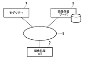
- FIG. 1 is a hardware configuration diagram showing an overview of a three-dimensional medical image processing system. As shown in the figure, in this system, a modality 1, an image storage server 2, and an image processing workstation 3 are connected via a network 9 in a communicable state.
- the modality 1 acquires a three-dimensional medical image V representing a subject, and specifically includes a CT apparatus, an MRI apparatus, an ultrasonic diagnostic apparatus, and the like.
- the image storage server 2 is a computer that stores and manages a three-dimensional medical image V acquired by the modality 1 and a medical image generated by image processing at the image processing workstation 3 in an image database.
- database management software for example, ORDB (Object Relational Database) management software.
- the image processing workstation 3 is a computer that performs image processing on the three-dimensional medical image V acquired from the modality 1 or the image storage server 2 in response to a request from the interpreter and displays the generated image.
- it includes an input device such as a keyboard and a mouse for inputting a request from a radiogram interpreter, a main memory having a capacity capable of storing the acquired three-dimensional medical image V, and a display for displaying the generated image. .
- the storage format of image data and communication between devices via the network 9 are based on a protocol such as DICOM (Digital Imaging and Communications Communications in Medicine).
- DICOM Digital Imaging and Communications Communications in Medicine
- FIG. 2 is a block diagram showing portions related to the projection image generation function of the image processing workstation 3.
- the image processing workstation 3 acquires an image acquisition unit 10 that acquires a three-dimensional medical image V of a patient to be interpreted from the modality 1 or the image storage server 2 in response to a request from the interpreter.
- a display setting unit 20 that sets a display target region and a non-display target region in the three-dimensional medical image V, and a plurality of lines of sight connecting the arbitrary viewpoint and each pixel on the projection plane.
- a plurality of exploration points are set in the display target area, and based on the pixel values of all exploration points on the line of sight, the pixel values of the pixels on the projection plane projected by the line of sight are determined, and a projection image is obtained.
- the projection image generation unit 60 includes an exploration point setting unit 30, a pixel value calculation unit 40, a projection And a decision unit 50.
- the image acquisition unit 10 acquires a three-dimensional medical image V of a patient to be interpreted from the modality 1 or the image storage server 2 in response to a request from an interpreter.
- the three-dimensional medical image V is obtained by dividing a multi-slice image into pixels (voxels) and arranging the pixels in a three-dimensional coordinate space. Is defined in a three-dimensional coordinate system in which the vertical axis is the y-axis and the vertical direction is the z-axis, and the pixel value of each pixel is associated with the coordinates of the position of the pixel.
- the display setting unit 20 includes a display target region (search point setting target region) and a non-display target region (search point non-target setting region) in the three-dimensional medical image V acquired by the image acquisition unit 10.
- a display target region search point setting target region
- a non-display target region search point non-target setting region
- the image interpreter has display / non-display information in each pixel of the 3D medical image V. Create a mask.
- the pixel value of the pixel in the non-display target region is set to be larger / smaller than the pixel value of the pixel of the display target region, or a change in pixel value or opacity (such as edge information)
- a change in pixel value or opacity such as edge information
- a plurality of sample images including a target region to be extracted are machine-learned in advance, and the biological tissue is extracted from the three-dimensional medical image V based on the learned result.
- the display target region and the non-display target region can also be set in the three-dimensional medical image V by a method different from the method exemplified above, such as setting to be displayed or hidden separately from the region.
- the projection image generation unit 60 receives the three-dimensional medical image V in which the display target region and the non-display target region are set as input, and the search point setting unit 30, the pixel value calculation unit 40, and the projection value determination unit 50 The pixel values (output pixel values) of the pixels constituting the projection image are obtained.
- the exploration point setting unit 30 uses, for example, the initial setting file, the viewpoint set by the input from the keyboard or mouse by the image reader, the projection plane F (size, position, number of pixels), for example, as shown in FIG.
- a plurality of exploration points P ji (i 1, 2,..., N; n is the number of exploration points on the line of sight E j ) sampled in (1).
- the pixel value calculation unit 40 refers to the mask having the display / non-display information of each pixel created in the display setting unit 20, and the eight pixels (neighbors near the search points P ji ). It is determined whether or not each pixel is a pixel set to non-display (a pixel in the non-display target area), and in the case of a pixel set to non-display, the pixel value of its neighboring pixels is described later. After that, the pixel value g (P ji ) at each search point P ji is calculated by interpolation based on the pixel values of the neighboring pixels of the search point.
- This replacement process is for calculating the pixel value of the search point P ji so that the pixel values of neighboring pixels in the non-display target region do not contribute.
- the projection value determination unit 50 to be described later determines the projection value by MIP / MinIP processing
- the pixel value of the neighboring pixel in the non-display target area is set to the maximum pixel value of all the pixels in the display target area / It can be replaced with the minimum value, or can be replaced with the maximum value / minimum value of the pixel values of the neighboring pixels in the display target area at the search point for the neighboring pixels.
- the display setting unit 20 is set so that pixels exceeding the threshold value 100 of the pixel value are excluded from the display target, and the neighboring pixels of the search point P ji are displayed in the display target region as shown in FIG.
- 90, 95, 95, and the pixel value of the pixel belonging to the non-display target area is 200
- the pixel value of the pixel Q of the non-display target area is set to the pixel of another neighboring pixel belonging to the display target area.
- the maximum value 95 of the values may be replaced.
- the pixel value of the pixel Q may be replaced with the average value of the pixel values of other neighboring pixels belonging to the display target region, or 0 for the MIP processing and the maximum possible value for the MinIP processing. It may be replaced with a fixed value such as a pixel value.
- the pixel value g (P ji ) at each search point P ji is obtained by linearly interpolating the pixel values of eight neighboring pixels constituting the grid including the search point P ji .
- the pixel value g (x, y, z) is obtained by the following equation (1).
- the pixel values of the neighboring pixels in the non-display target area are the pixel values after the above replacement process.
- the pixel value g (P ji ) at each search point P ji is obtained by linearly interpolating the pixel values of the eight pixels constituting the grid including the search point P ji. Then, the pixel values of 64 pixels (4 pixels in the x-axis direction ⁇ 4 pixels in the y-axis direction ⁇ 4 pixels in the z-axis direction) constituting the grid including the search point P ji are subjected to cubic interpolation. You may make it ask.
- the projection value determination unit 50 determines the output pixel value C j of each pixel on the projection plane based on the pixel value g (P ji ) at each search point P ji calculated by the pixel value calculation unit 40. To do.
- the output pixel value C j of the pixel on the projection plane projected by E j is determined, or the product of the luminance value and the opacity at each search point P ji is added along each line of sight E j.
- the result is determined as the output pixel value C j of the projection pixel on the projection plane through which the line of sight E j passes (volume rendering method).
- Such processing is performed for each line of sight, output pixel values of all projection pixels on the projection plane are determined, and a projection image (maximum value projection image / minimum value projection image) is generated.
- the generated projection image is displayed on the display of the image processing workstation 3 by the image display unit 70.
- the search point setting unit 30 connects a plurality of pixels on the projection plane on which the three-dimensional image is projected and an arbitrary viewpoint.
- a plurality of search points are set in the display target region of the three-dimensional image along the line of sight, and the pixel value calculation unit 40 performs an interpolation operation based on the pixel values of the search points and the pixel values of the neighboring pixels of the search points.
- the projection value determination unit 50 determines the pixel value of the pixel on the projection plane for each line of sight based on the calculated pixel value of each search point, and is a projection image composed of each pixel on the projection plane
- the pixel value calculation unit 40 When the pixel value calculation unit 40 generates a pixel in the vicinity of the search point, if the pixel near the search point is a pixel outside the display target (excluding the search point setting target), Since the pixel value of the exploration point is calculated so as not to contribute, The pixel values of the pixels outside the display target (excluding the search point setting target) will not affect the determination of the pixel values of each pixel on the projection plane, and artifacts due to the non-setting target region will be suppressed.
- the image processing workstation 3 performs both image processing and image display.
- an image processing server is separately provided and connected to the network 9, and image processing is performed on this image processing server. You may make it let.
- distributed processing is achieved. For example, when images are displayed on a plurality of terminals, it is not necessary to install a plurality of high-performance image processing workstations, which contributes to a reduction in the cost of the entire system.
- FIG. 1 is a schematic configuration diagram of a three-dimensional medical image processing system according to an embodiment of the present invention.
- the block diagram which shows the projection image production
Landscapes
- Engineering & Computer Science (AREA)
- Health & Medical Sciences (AREA)
- Life Sciences & Earth Sciences (AREA)
- Physics & Mathematics (AREA)
- Medical Informatics (AREA)
- Surgery (AREA)
- Heart & Thoracic Surgery (AREA)
- Theoretical Computer Science (AREA)
- Biophysics (AREA)
- Veterinary Medicine (AREA)
- General Physics & Mathematics (AREA)
- Nuclear Medicine, Radiotherapy & Molecular Imaging (AREA)
- Public Health (AREA)
- Pathology (AREA)
- Radiology & Medical Imaging (AREA)
- Biomedical Technology (AREA)
- General Health & Medical Sciences (AREA)
- Molecular Biology (AREA)
- Computer Graphics (AREA)
- Animal Behavior & Ethology (AREA)
- Human Computer Interaction (AREA)
- Optics & Photonics (AREA)
- High Energy & Nuclear Physics (AREA)
- Apparatus For Radiation Diagnosis (AREA)
- Magnetic Resonance Imaging Apparatus (AREA)
- Measuring And Recording Apparatus For Diagnosis (AREA)
- Image Generation (AREA)
Abstract
Selon l'invention, une image de projection composée de pixels respectifs sur un plan de projection est générée: par détermination de plusieurs points d'exploration dans une zone à afficher d'une image tridimensionnelle, le long de lignes visuelles raccordant les pixels respectifs sur le plan de projection sur lequel l'image tridimensionnelle est projetée ainsi qu'un point de vue arbitraire; par calcul de la valeur des pixels respectifs des points d'exploration par une opération d'interpolation fondée sur la valeur des pixels situés à proximité des points d'exploration; et par détermination de la valeur des pixels situés sur le plan de projection, dans les lignes visuelles respectives, sur la base de la valeur des pixels calculée. La valeur des pixels des points d'exploration est calculée de telle sorte que, lorsqu'un pixel situé à proximité des points d'exploration appartient à une zone autre que la zone à afficher, la valeur du pixel situé à proximité immédiate dans la zone autre que la zone à afficher n'est pas prise en compte. En conséquence, la survenue d'un artéfact imputable à la zone autre que la zone à afficher est empêchée pendant la génération de l'image de projection sur laquelle sont projetés les pixels de l'image tridimensionnelle comprenant la zone autre que la zone à afficher.
Priority Applications (2)
| Application Number | Priority Date | Filing Date | Title |
|---|---|---|---|
| EP09729136.3A EP2272427B1 (fr) | 2008-04-03 | 2009-03-31 | Dispositif, procédé et programme de traitement d'image |
| US12/736,382 US8933926B2 (en) | 2008-04-03 | 2009-03-31 | Image processing apparatus, method, and program |
Applications Claiming Priority (2)
| Application Number | Priority Date | Filing Date | Title |
|---|---|---|---|
| JP2008-097205 | 2008-04-03 | ||
| JP2008097205A JP4668289B2 (ja) | 2008-04-03 | 2008-04-03 | 画像処理装置および方法並びにプログラム |
Publications (1)
| Publication Number | Publication Date |
|---|---|
| WO2009122724A1 true WO2009122724A1 (fr) | 2009-10-08 |
Family
ID=41135127
Family Applications (1)
| Application Number | Title | Priority Date | Filing Date |
|---|---|---|---|
| PCT/JP2009/001494 WO2009122724A1 (fr) | 2008-04-03 | 2009-03-31 | Dispositif, procédé et programme de traitement d'image |
Country Status (4)
| Country | Link |
|---|---|
| US (1) | US8933926B2 (fr) |
| EP (1) | EP2272427B1 (fr) |
| JP (1) | JP4668289B2 (fr) |
| WO (1) | WO2009122724A1 (fr) |
Families Citing this family (6)
| Publication number | Priority date | Publication date | Assignee | Title |
|---|---|---|---|---|
| JP5257958B2 (ja) * | 2011-06-01 | 2013-08-07 | 株式会社日立メディコ | 画像表示装置、画像表示システムおよび画像表示方法 |
| KR101370496B1 (ko) * | 2013-09-26 | 2014-03-06 | 한국건설기술연구원 | 복합매질로 이루어진 시편에 대한 X-ray CT 영상의 최소 단위에 존재하는 각 순수매질의 부피비 측정방법 |
| US9842424B2 (en) * | 2014-02-10 | 2017-12-12 | Pixar | Volume rendering using adaptive buckets |
| KR101586765B1 (ko) * | 2015-02-27 | 2016-01-25 | 주식회사 다우인큐브 | 반도체 공정 기반 3차원 가상 형상 모델링 방법 |
| CN106408651B (zh) * | 2016-08-26 | 2019-03-05 | 东南大学 | 一种基于像素提取的三维数值颗粒成型方法 |
| CN112330656B (zh) * | 2020-11-20 | 2024-04-05 | 北京航星机器制造有限公司 | 一种安检ct图像危险品植入方法和系统 |
Citations (2)
| Publication number | Priority date | Publication date | Assignee | Title |
|---|---|---|---|---|
| JP2006000127A (ja) * | 2004-06-15 | 2006-01-05 | Fuji Photo Film Co Ltd | 画像処理方法および装置並びにプログラム |
| JP2006055213A (ja) * | 2004-08-17 | 2006-03-02 | Konica Minolta Medical & Graphic Inc | 画像処理装置、及びプログラム |
Family Cites Families (6)
| Publication number | Priority date | Publication date | Assignee | Title |
|---|---|---|---|---|
| JPH06290276A (ja) * | 1993-02-15 | 1994-10-18 | Philips Electron Nv | 3次元場面の映像化用配置及び方法 |
| US6058218A (en) | 1997-11-10 | 2000-05-02 | General Electric Company | Enhanced visualization of weak image sources in the vicinity of dominant sources |
| US6717578B1 (en) * | 1998-02-17 | 2004-04-06 | Sun Microsystems, Inc. | Graphics system with a variable-resolution sample buffer |
| JP4109224B2 (ja) * | 2004-07-01 | 2008-07-02 | ザイオソフト株式会社 | 展開画像投影方法、展開画像投影プログラム、展開画像投影装置 |
| WO2006095017A2 (fr) * | 2005-03-10 | 2006-09-14 | Bracco Imaging S.P.A. | Systemes et procedes pour optimiser le rendu volumetrique d'une region voulue ('vecteur de tension') |
| US20080232694A1 (en) * | 2007-03-21 | 2008-09-25 | Peter Sulatycke | Fast imaging data classification method and apparatus |
-
2008
- 2008-04-03 JP JP2008097205A patent/JP4668289B2/ja active Active
-
2009
- 2009-03-31 WO PCT/JP2009/001494 patent/WO2009122724A1/fr active Application Filing
- 2009-03-31 EP EP09729136.3A patent/EP2272427B1/fr active Active
- 2009-03-31 US US12/736,382 patent/US8933926B2/en active Active
Patent Citations (2)
| Publication number | Priority date | Publication date | Assignee | Title |
|---|---|---|---|---|
| JP2006000127A (ja) * | 2004-06-15 | 2006-01-05 | Fuji Photo Film Co Ltd | 画像処理方法および装置並びにプログラム |
| JP2006055213A (ja) * | 2004-08-17 | 2006-03-02 | Konica Minolta Medical & Graphic Inc | 画像処理装置、及びプログラム |
Also Published As
| Publication number | Publication date |
|---|---|
| JP2009247490A (ja) | 2009-10-29 |
| EP2272427A4 (fr) | 2017-02-22 |
| US20110115785A1 (en) | 2011-05-19 |
| EP2272427A1 (fr) | 2011-01-12 |
| EP2272427B1 (fr) | 2019-09-04 |
| JP4668289B2 (ja) | 2011-04-13 |
| US8933926B2 (en) | 2015-01-13 |
Similar Documents
| Publication | Publication Date | Title |
|---|---|---|
| US7529396B2 (en) | Method, computer program product, and apparatus for designating region of interest | |
| US9818200B2 (en) | Apparatus and method for multi-atlas based segmentation of medical image data | |
| JP5643304B2 (ja) | 胸部トモシンセシスイメージングにおけるコンピュータ支援肺結節検出システムおよび方法並びに肺画像セグメント化システムおよび方法 | |
| US10692272B2 (en) | System and method for removing voxel image data from being rendered according to a cutting region | |
| US8659602B2 (en) | Generating a pseudo three-dimensional image of a three-dimensional voxel array illuminated by an arbitrary light source by a direct volume rendering method | |
| EP3136338A1 (fr) | Appareil de traitement d'informations, procédé de traitement d'informations et programme | |
| JP4668289B2 (ja) | 画像処理装置および方法並びにプログラム | |
| JP6824845B2 (ja) | 画像処理システム、装置、方法およびプログラム | |
| JP6215057B2 (ja) | 可視化装置、可視化プログラムおよび可視化方法 | |
| CN103325139A (zh) | 医用图像处理装置及医用图像处理方法 | |
| JP4885042B2 (ja) | 画像処理方法および装置ならびにプログラム | |
| CN111311705B (zh) | 基于webgl的高适应性医学影像多平面重建方法及系统 | |
| JP5194138B2 (ja) | 画像診断支援装置およびその動作方法、並びに画像診断支援プログラム | |
| CN104240271A (zh) | 医用图像处理装置 | |
| US20220343589A1 (en) | System and method for image processing | |
| AU2019430369A1 (en) | VRDS 4D medical image-based vein Ai endoscopic analysis method and product | |
| JP4122314B2 (ja) | 投影画像処理方法、投影画像処理プログラム、投影画像処理装置 | |
| US20210049809A1 (en) | Image processing method and apparatus | |
| JP2006346094A (ja) | 検出情報の出力方法及び医用画像処理システム | |
| CN114365188A (zh) | 基于vrds ai下腔静脉影像的分析方法及产品 | |
| EP2823764B1 (fr) | Dispositif, procédé et programme de traitement d'image médicale | |
| WO2020173054A1 (fr) | Procédé et produit de traitement d'image médicale 4d vrds | |
| CN111210898A (zh) | 一种对dicom数据进行处理的方法和装置 | |
| EP2449527B1 (fr) | Soustraction d'image numérique | |
| JP2006000126A (ja) | 画像処理方法および装置並びにプログラム |
Legal Events
| Date | Code | Title | Description |
|---|---|---|---|
| 121 | Ep: the epo has been informed by wipo that ep was designated in this application |
Ref document number: 09729136 Country of ref document: EP Kind code of ref document: A1 |
|
| NENP | Non-entry into the national phase |
Ref country code: DE |
|
| WWE | Wipo information: entry into national phase |
Ref document number: 2009729136 Country of ref document: EP |
|
| WWE | Wipo information: entry into national phase |
Ref document number: 12736382 Country of ref document: US |