WO2009104654A1 - 同軸ケーブル用コネクタ - Google Patents
同軸ケーブル用コネクタ Download PDFInfo
- Publication number
- WO2009104654A1 WO2009104654A1 PCT/JP2009/052822 JP2009052822W WO2009104654A1 WO 2009104654 A1 WO2009104654 A1 WO 2009104654A1 JP 2009052822 W JP2009052822 W JP 2009052822W WO 2009104654 A1 WO2009104654 A1 WO 2009104654A1
- Authority
- WO
- WIPO (PCT)
- Prior art keywords
- terminal
- connector
- housing
- shell
- coaxial cable
- Prior art date
Links
Images


Classifications
-
- H—ELECTRICITY
- H01—ELECTRIC ELEMENTS
- H01R—ELECTRICALLY-CONDUCTIVE CONNECTIONS; STRUCTURAL ASSOCIATIONS OF A PLURALITY OF MUTUALLY-INSULATED ELECTRICAL CONNECTING ELEMENTS; COUPLING DEVICES; CURRENT COLLECTORS
- H01R24/00—Two-part coupling devices, or either of their cooperating parts, characterised by their overall structure
- H01R24/38—Two-part coupling devices, or either of their cooperating parts, characterised by their overall structure having concentrically or coaxially arranged contacts
- H01R24/40—Two-part coupling devices, or either of their cooperating parts, characterised by their overall structure having concentrically or coaxially arranged contacts specially adapted for high frequency
-
- H—ELECTRICITY
- H01—ELECTRIC ELEMENTS
- H01R—ELECTRICALLY-CONDUCTIVE CONNECTIONS; STRUCTURAL ASSOCIATIONS OF A PLURALITY OF MUTUALLY-INSULATED ELECTRICAL CONNECTING ELEMENTS; COUPLING DEVICES; CURRENT COLLECTORS
- H01R13/00—Details of coupling devices of the kinds covered by groups H01R12/70 or H01R24/00 - H01R33/00
- H01R13/40—Securing contact members in or to a base or case; Insulating of contact members
- H01R13/42—Securing in a demountable manner
- H01R13/422—Securing in resilient one-piece base or case, e.g. by friction; One-piece base or case formed with resilient locking means
- H01R13/4223—Securing in resilient one-piece base or case, e.g. by friction; One-piece base or case formed with resilient locking means comprising integral flexible contact retaining fingers
-
- H—ELECTRICITY
- H01—ELECTRIC ELEMENTS
- H01R—ELECTRICALLY-CONDUCTIVE CONNECTIONS; STRUCTURAL ASSOCIATIONS OF A PLURALITY OF MUTUALLY-INSULATED ELECTRICAL CONNECTING ELEMENTS; COUPLING DEVICES; CURRENT COLLECTORS
- H01R13/00—Details of coupling devices of the kinds covered by groups H01R12/70 or H01R24/00 - H01R33/00
- H01R13/62—Means for facilitating engagement or disengagement of coupling parts or for holding them in engagement
- H01R13/629—Additional means for facilitating engagement or disengagement of coupling parts, e.g. aligning or guiding means, levers, gas pressure electrical locking indicators, manufacturing tolerances
- H01R13/631—Additional means for facilitating engagement or disengagement of coupling parts, e.g. aligning or guiding means, levers, gas pressure electrical locking indicators, manufacturing tolerances for engagement only
-
- H—ELECTRICITY
- H01—ELECTRIC ELEMENTS
- H01R—ELECTRICALLY-CONDUCTIVE CONNECTIONS; STRUCTURAL ASSOCIATIONS OF A PLURALITY OF MUTUALLY-INSULATED ELECTRICAL CONNECTING ELEMENTS; COUPLING DEVICES; CURRENT COLLECTORS
- H01R2103/00—Two poles
Definitions
- the present invention relates to a coaxial cable connector used for connecting a coaxial cable such as an antenna line for transmitting a high-frequency signal.
- a coaxial cable used as an antenna wire or the like is covered with a braided shield on the outside of a core wire covered with an insulating coating and further covered with an insulating sheath to block electrical noise such as electromagnetic waves and static electricity. It has a configuration.
- a coaxial cable connector for connecting such a coaxial cable to another coaxial cable or an electronic device for example, there is a configuration shown in FIG. 6 (see, for example, JP-A-2006-24499).
- the coaxial cable connector 201 shown in FIG. 6 includes a first connector 208 attached to the end of the coaxial cable D1, a second connector 9 attached to the end of the other coaxial cable D2, and connected to the first connector 208, Consists of.
- the coaxial cables D1 and D2 include a core wire 11, an insulating coating 12 covering the core wire 11, a braid (not shown) that covers the insulating coating 12, and a sheath (not shown) that covers the braid.
- a peeling process is performed so that the insulating coating 12 and the core wire 11 are exposed in a predetermined length.
- the first connector 208 includes an electric wire connecting portion 223 for crimping the core wire 11 of the coaxial cable D1, a rod-shaped first electric connecting portion 221 connected to the second connector 9, the electric wire connecting portion 223, and the first electric connecting portion.
- a first terminal 202 having a first connecting portion 222 for connecting to 221; a cylindrical housing 203 for accommodating the first terminal 202; and a cylindrical shape made of a conductive material, covering the housing 203 and coaxially.
- a shell 204 connected to the braid of the cable D1.
- the first connecting part 222 is provided in a rod shape having a larger diameter than the first electrical connecting part 221.
- the second connector 9 includes a connecting portion 53 for crimping the core wire 11 of another coaxial cable D2, a cylindrical second electric connecting portion 51 connected to the first electric connecting portion 221, the connecting portion 53, and the second.
- a second terminal 5 having a second connecting portion 52 that connects the electrical connecting portion 51, a cylindrical second housing 6 that accommodates the second terminal 5, and a cylindrical shape made of a conductive material.
- a second shell 7 that covers the housing 6 and is inserted between the housing 203 and the shell 204.
- the coaxial cable connector 201 configured as described above is brought closer to each other along the fitting direction K parallel to the longitudinal direction of the coaxial cables D1 and D2, so that the first electrical connection portion 221 is inserted into the second electrical connection portion 51.
- the second electrical connection portion 51 and the first electrical connection portion 221 are electrically connected to each other.
- the second shell 7 is inserted between the housing 203 and the shell 204, and the second shell 7 and the shell 204 are electrically connected to each other.
- the first electrical connection portion 221 is not connected to the second electrical connection portion 51 in the fitting state shown in FIG. There is a case where it is not completely inserted, that is, fitted to the back side.
- the first electrical connection part 221 positioned outside the second electrical connection part 51 A space is generated around an end portion (indicated by symbol S in FIG. 6) near the one connecting portion 222, and this space causes a disturbance in the characteristic impedance of the coaxial cable connector 201, that is, an impedance mismatching portion occurs.
- an object of the present invention is to provide a coaxial cable connector that can maintain good high frequency characteristics of the coaxial cable by reducing the impedance mismatching portion of the coaxial cable connector itself.
- a coaxial cable connector of the present invention is attached to a first connector attached to a terminal of a first coaxial cable and a terminal of a second coaxial cable or an electronic device, and is connected to the first connector.
- a first terminal having a wire connecting portion connected to a core wire of the first coaxial cable and a first electrical connecting portion connected to the second connector.
- a cylindrical first housing that accommodates the first terminal; a first shell that is formed of a conductive material into a cylindrical shape, covers the first housing, and is connected to the braid of the first coaxial cable;
- the second connector is connected to the first electrical connection portion by being fitted to the connection portion connected to the core wire of the second coaxial cable or the circuit of the electronic device and the first electrical connection portion.
- a second terminal having two electrical connection portions, a cylindrical second housing that accommodates the second terminal, and a cylindrical shape made of a conductive material, covering the second housing, and the first housing and the A second shell inserted between the first shell and the first connector, and the first shell is inserted between the first housing and the first shell.
- a coaxial cable connector having pushing means for pushing one terminal toward the second terminal.
- the push-out means protrudes from the edge of the first housing on the side away from the second terminal and from the edge toward the first shell, and the second housing An outer projecting portion pressed to the side away from the second terminal by the shell and an inner projecting portion projecting from the edge to the inside of the first housing, and the outer projecting portion being pressed and displaced to the side away from the second terminal. And an inner protrusion that is displaced toward the second terminal and presses the first terminal toward the second terminal.
- the push-out means is provided on the first protruding portion protruding from the outer surface of the first housing toward the first shell, and on the outer surface of the first terminal, A taper surface inclined in a direction away from the inner surface of the first housing as it is away from the second terminal, and a portion of the inner surface of the first housing that protrudes from the back side of the first protrusion, A second projecting portion that presses the tapered surface when the second shell enters between the first projecting portion and the first shell, and the tapered surface is pressed by the second projecting portion. Accordingly, the tapered surface may slide on the surface of the second projecting portion and the first terminal may be pushed out toward the second terminal.
- the coaxial cable connector when the first connector is inserted into the second shell between the first housing and the first shell, the first terminal is directed toward the second terminal. Since the extrusion means for extruding is provided, the first electrical connection portion and the second electrical connection portion can be completely fitted over the entire length without rattling, and the impedance of the coaxial cable connector itself is reduced. Since the number of matching portions can be reduced, it is possible to provide a coaxial cable connector that can maintain good high-frequency characteristics of the coaxial cable.
- the push-out means protrudes toward the first shell side from the edge of the first housing on the side away from the second terminal, and away from the second terminal by the second shell.
- An outer protrusion that is pressed against the inner side of the first housing from the edge, and a side closer to the second terminal when the outer protrusion is pressed and displaced away from the second terminal.
- an inner projecting portion that presses the first terminal toward the second terminal, so that the first electrical connection portion and the second electrical connection portion are not rattled.
- the coaxial cable connector can maintain a good high-frequency characteristic of the coaxial cable because the impedance mismatching portion of the coaxial cable connector itself can be reduced. It is possible to provide.
- the push-out means is provided on the first protrusion protruding from the outer surface of the first housing toward the first shell and on the outer surface of the first terminal, and as the distance from the second terminal increases, A tapered surface inclined in a direction away from the inner surface of the first housing; and a portion of the inner surface of the first housing that protrudes from a portion located on the back side of the first protruding portion; the first protruding portion and the first shell; A second protrusion that presses the taper surface when the second shell enters between the taper surface and the taper surface is pressed against the second protrusion.
- FIG. 1 It is a section perspective view showing the connector for coaxial cables concerning a 1st embodiment of the present invention.
- FIG. 4 shows the state which the 1st connector shown by FIG. 4 which comprises the connector for coaxial cables which concerns on the 2nd Embodiment of this invention, and the 2nd connector were fitted.
- FIG. 1 is a cross-sectional perspective view showing a coaxial cable connector according to a first embodiment of the present invention.
- FIG. 2 is a cross-sectional view showing a first connector constituting the coaxial cable connector shown in FIG.
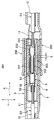
- FIG. 3 is a cross-sectional view showing a state in which the first connector and the second connector constituting the coaxial cable connector shown in FIG. 1 are fitted.
- the coaxial cable connector 1 of the present invention is a coaxial cable connector 1 used for connection of coaxial cables D1 and D2 such as antenna lines for transmitting high-frequency signals.
- the coaxial cable connector 1 includes a first connector 8 attached to the end of the coaxial cable D1 and a second connector attached to the end of another coaxial cable D2 and connected to the first connector 8. And a connector 9.
- the coaxial cables D1 and D2 are electric wires that transmit a high-frequency signal.
- the coaxial cables D1 and D2 are, respectively, a conductive core wire 11, a synthetic resin insulation coating 12 that covers the core wire 11, and the insulation coating 12 covering and shielding the core wire 11.
- a conductive braid (not shown) and a synthetic resin sheath (not shown) covering the braid, and the braid, the insulation coating 12 and the core wire 11 are exposed at predetermined lengths, respectively. Peeling treatment is applied so that it is in a finished state.
- the first connector 8 includes a first terminal 2, a housing 3 that accommodates the first terminal 2, a shell 4 that covers the housing 3 and is connected to the braid of the coaxial cable D1, have.
- the first terminal 2 is obtained by subjecting a conductive metal plate to a pressing process or the like, and includes an electric wire connecting portion 23 for crimping the exposed core wire 11 of the coaxial cable D1 with a caulking piece, and a second connector. 9 is connected to the second terminal 5 to be described later and connected to the second terminal 5, and the first electrical connection part 21 connecting the wire connection part 23 and the first electrical connection part 21. 1 connecting portion 22.
- the first connecting portion 22 is provided in a rod shape having a larger diameter than the first electric connecting portion 21.
- the housing 3 is formed in a cylindrical shape with an insulating synthetic resin.
- the housing 3 receives a second electrical connection portion 51 of the second terminal 5 to be described later from an opening 30 (see FIG. 2) provided on the side away from the wire connection portion 23.
- the shell 4 is obtained by subjecting a conductive metal plate to press treatment or the like, and is electrically connected to the braid and is also electrically connected to a second shell 7 described later of another coaxial cable D2. By doing this, this braid is connected to the braid of the other coaxial cable D2. Alternatively, this braid is grounded to an appropriate grounding part. Further, the shell 4 shields the first terminal 2 by covering the housing 3. A portion covering the housing 3 is provided in a cylindrical shape as shown in FIGS. 1 to 3, and a space for accommodating the second shell 7 is provided between the housing 3 and the housing 3. The portion of the shell 4 that covers the housing 3 receives the second shell 7 from an opening 40 (see FIG. 2) provided on the side away from the wire connection portion 23.
- the second connector 9 covers the second terminal 5, a cylindrical second synthetic resin housing 6 that accommodates the second terminal 5, and the second housing 6. And a second shell 7 connected to the braid of the coaxial cable D2.
- the second terminal 5 is obtained by subjecting a conductive metal plate to a pressing process or the like.
- the second terminal 5 includes a connection portion 53 for crimping the exposed core wire 11 of another coaxial cable D2 with a caulking piece, A cylindrical second electrical connection portion 51 that is fitted to the first electrical connection portion 21 of the connector 8 and connected to the first electrical connection portion 21, the connection portion 53, and the second electrical connection portion 51. And a second connecting portion 52 to be connected.
- the second shell 7 is obtained by subjecting a conductive metal plate to press treatment or the like. By electrically connecting to the braid and electrically connecting to the shell 4 of the coaxial cable D1, This braid is connected to the braid of the coaxial cable D1. Alternatively, this braid is grounded to an appropriate grounding part. Further, the second shell 7 shields the second terminal 5 by covering the second housing 6.
- the second electrical connection portion 51 of the second terminal 5 protrudes outside the second housing 6, and the second shell 7 is provided in a cylindrical shape covering the housing 6 and the second electrical connection portion 51. It has been. Further, a space for accommodating the housing 3 is provided between the second shell 7 and the second electrical connection portion 51. Such a second shell 7 is inserted between the housing 3 and the shell 4 and accommodates the housing 3 between the second shell 7 and the second electrical connection portion 51.
- the first connector 8 includes a pressing portion 32 as an extruding means that pushes the first terminal 2 toward the second terminal 5 by inserting the second shell 7 between the second housing 3 and the shell 4. have.
- the pressing portion 32 has an edge portion 32 a on the side away from the second terminal 5 of the housing 3, and an outer side protruding from the edge portion 32 a to the shell 4 side and pressed to the side away from the second terminal 5 by the second shell 7.
- the projection 32b projects from the edge 32a to the inside of the housing 3, and the outer projection 32b is pressed and displaced to the side away from the second terminal 5, thereby being displaced to the side closer to the second terminal 5, And an inner protrusion 32c that presses the first terminal 2 toward the second terminal 5.
- Such a pressing portion 32 has a shape extending in a plate shape along the thickness direction (indicated by an arrow Y in the figure) of the outer wall 31 constituting the housing 3, that is, the radial direction of the housing 3.
- the coaxial cable connector 1 configured as described above is brought closer to each other along the fitting direction K parallel to the longitudinal direction of the coaxial cables D1 and D2, so that the first electrical connection portion 21 is inserted into the second electrical connection portion 51.
- the second electrical connection portion 51 and the first electrical connection portion 21 are fitted to each other and electrically connected.
- the second shell 7 is inserted between the housing 3 and the shell 4 so that the second shell 7 and the shell 4 are electrically connected to each other.
- the first connector 8 has the pressing portion 32 that pushes the first terminal 2 toward the second terminal 5 by inserting the second shell 7 between the housing 3 and the shell 4. Therefore, even if there is a backlash between the first connector 8 and the second connector 9 due to variations in tolerance dimensions of each component, the first electrical connection portion is in the fitted state. 21 can be completely inserted or fitted into the second electrical connection portion 51 over its entire length, and this state can be maintained. In the coaxial cable connector 1 of the present invention, the first electrical connection portion 21 is not completely inserted to the back side of the second electrical connection portion 51 (see the conventional product shown in FIG. 6). ) Can be prevented, and the impedance mismatching portion of the coaxial cable connector 1 itself can be reduced. Therefore, the high frequency characteristics of the coaxial cables D1, D2 can be kept good.
- FIG. 4 is a cross-sectional view showing the first connector constituting the coaxial cable connector according to the second embodiment of the present invention.
- FIG. 5 is a cross-sectional view showing a state where the first connector and the second connector shown in FIG. 4 constituting the coaxial cable connector according to the second embodiment of the present invention are fitted.
- the same components as those in the first embodiment described above are denoted by the same reference numerals and description thereof is omitted.
- the coaxial cable connector 101 of this embodiment shown in FIG. 5 is a first connector 108 attached to the end of the coaxial cable D1, and a second connector attached to the end of another coaxial cable D2 and connected to the first connector 108. And a connector 9.
- the first connector 108 includes a terminal 102, a housing 103 that accommodates the terminal 102, a shell 4 that covers the housing 103 and is connected to the braid of the coaxial cable D1, and the housing 103 and the shell. 4 and an extruding means for extruding the terminal 102 toward the second terminal 5 by inserting the second shell 7 therebetween.
- This pushing means is provided on the outer surface of the first connecting portion 22 of the terminal 102 and the first projecting portion 33 projecting from the outer surface of the outer wall 31 constituting the housing 103 to the shell 4 side, and is separated from the second terminal 5. And a second projecting portion projecting from a portion of the inner surface of the outer wall 31 located on the back side of the first projecting portion 33. 34.
- the recess 24 is provided by stamping a metal plate constituting the terminal 102. Further, the second protrusion 34 is displaced toward the inside of the housing 103 when the second shell 7 enters between the first protrusion 33 and the shell 4, that is, displaced along the arrow Y direction. Then, the tapered surface 24 a is pressed toward the inside of the housing 103.
- the tapered surface 24 a is pressed by the second projecting portion 34, whereby the tapered surface 24 a slides on the surface of the second projecting portion 34 and the terminal 102 is pushed out toward the second terminal 5.
- the second projecting portion 34 is provided with an inclined surface 34a inclined at the same angle as the tapered surface 24a, and the tapered surface 24a slides on the inclined surface 34a.
- the first electrical connection portion 21 is inserted into the second electrical connection portion 51, and the second electrical connection portion 51 and the 1 electrical connection part 21 mutually fits, and is electrically connected.
- the second shell 7 is inserted between the housing 103 and the shell 4 and the second shell 7 and the shell 4 are electrically connected to each other.
- the second shell 7 hits the first protrusion 33, and the housing 103 is pressed while pushing the first protrusion 33 inside the housing 103.
- the second protrusion 34 presses the tapered surface 24 a toward the inside of the housing 103, the tapered surface 24 a slides on the inclined surface 34 a, and the terminal 102 is pushed toward the second terminal 5.
- the 1st electrical connection part 21 is completely accommodated in the 2nd electrical connection part 51 over the full length.
- the taper surface 24a is pressed by the 2nd protrusion part 34, the 1st electrical connection part 21 of this state is prevented from rattling with respect to the 2nd electrical connection part 51.
- the first connector 108 has an extruding means that pushes the terminal 102 toward the second terminal 5 by inserting the second shell 7 between the housing 103 and the shell 4. Therefore, even if there is a backlash between the first connector 108 and the second connector 9 due to variation in the tolerance dimension of each component, the first electrical connection portion 21 is not It can be completely inserted or fitted into the second electrical connection portion 51 over the entire length, and this state can be maintained.
- the first electrical connection portion 21 is not completely inserted to the back side of the second electrical connection portion 51 (see the conventional product shown in FIG. 6). ) Can be prevented, and impedance mismatching portions of the coaxial cable connector 101 itself can be reduced. Therefore, the high frequency characteristics of the coaxial cables D1, D2 can be kept good.
- the first connectors 8 and 108 are provided with the male first terminals 2 and 102, and the second connector 9 is provided with the female second terminals 5.
- the first connector may be provided with a female terminal
- the second connector may be provided with a male second terminal.
- the second connector 9 is attached to the end of the coaxial cable D2 in the first and second embodiments described above.
- the second connector is connected to the circuit of the electronic device. May be.
- the connecting portion is connected to the circuit, and the second shell is connected to a conductive member grounded to the ground side.
- the coaxial cable connector provided with the pushing means for pushing out the terminal when the connector is fitted, even when there is a backlash between the connectors due to variation in the tolerance dimension of each component.
- the impedance mismatching part of the coaxial cable connector itself can be reduced, and the high frequency characteristics of the coaxial cable can be kept good.
Landscapes
- Coupling Device And Connection With Printed Circuit (AREA)
Abstract
同軸ケーブル用コネクタ自身のインピーダンス不整合部を少なくして同軸ケーブルの高周波特性を良好に保つことができる同軸ケーブル用コネクタを提供する。
同軸ケーブル用コネクタ1は、同軸ケーブルD1の端末に取り付けられる第1コネクタ8と、他の同軸ケーブルD2の端末に取り付けられ、前記第1コネクタ8と接続される第2コネクタ9と、で構成される。前記第1コネクタ8は、ハウジング3とシェル4との間に第2シェル7が挿入されることによって第1端子2を第2端子5に向かって押し出す押圧部32を有している。
Description
本発明は、高周波信号を伝送するアンテナ線などの同軸ケーブルの接続に用いられる同軸ケーブル用コネクタに関するものである。
一般に、アンテナ線等として用いられる同軸ケーブルは、電磁波や静電気などの電気的ノイズを遮断するために、絶縁被覆により覆われた芯線の外側を編組シールドによって覆い、さらにその外側を絶縁シースにより覆った構成となっている。そして、この様な同軸ケーブルを他の同軸ケーブルや電子機器に接続する同軸ケーブル用コネクタとして、例えば図6に示す構成のものがある(例えば、特開2006-24499号公報を参照。)。
図6に示す同軸ケーブル用コネクタ201は、同軸ケーブルD1の端末に取り付けられる第1コネクタ208と、他の同軸ケーブルD2の端末に取り付けられ、第1コネクタ208と接続される第2コネクタ9と、で構成される。
上記同軸ケーブルD1,D2は、芯線11と、芯線11を被覆した絶縁被覆12と、絶縁被覆12を覆う図示しない編組と、この編組を被覆した図示しないシースと、で構成されており、前記編組、絶縁被覆12及び芯線11がそれぞれ所定の長さで露出した状態になるように皮むき処理が施されている。
上記第1コネクタ208は、同軸ケーブルD1の芯線11を圧着する電線接続部223と第2コネクタ9に接続される棒状の第1電気接続部221と前記電線接続部223と前記第1電気接続部221とを連結する第1連結部222とを有する第1端子202と、この第1端子202を収容する円筒状のハウジング203と、導電性材料により円筒状に構成され、ハウジング203を覆いかつ同軸ケーブルD1の編組に接続されるシェル204と、を有している。また、前記第1連結部222は、前記第1電気接続部221よりも大径の棒状に設けられている。
上記第2コネクタ9は、他の同軸ケーブルD2の芯線11を圧着する接続部53と前記第1電気接続部221と接続される円筒状の第2電気接続部51と接続部53と前記第2電気接続部51とを連結する第2連結部52とを有する第2端子5と、この第2端子5を収容する円筒状の第2ハウジング6と、導電性材料により円筒状に構成され、第2ハウジング6を覆いかつ前記ハウジング203と前記シェル204との間に挿入される第2シェル7と、を有している。
上記構成の同軸ケーブル用コネクタ201は、同軸ケーブルD1,D2の長手方向と平行な嵌合方向Kに沿って互いに近付けられることにより、第2電気接続部51内に第1電気接続部221が挿入されてこれら第2電気接続部51と第1電気接続部221とが互いに電気接続される。そして、第2シェル7がハウジング203とシェル204との間に挿入されて第2シェル7とシェル204とが互いに電気接続される。
しかしながら、上述した従来の同軸ケーブル用コネクタ201においては、各構成部品の公差寸法のばらつきにより生じるガタにより、図6に示す嵌合状態において、第1電気接続部221が第2電気接続部51の奥側まで完全に挿入、即ち嵌合、されていない状態となることがあった。このように第1電気接続部221が第2電気接続部51の奥側まで完全に挿入されてない状態の場合、第2電気接続部51の外部に位置付けられた第1電気接続部221の第1連結部222寄りの端部(図6中に符号Sで示す。)の周りに空間が生じ、この空間により同軸ケーブル用コネクタ201の特性インピーダンスに乱れが生じ、即ちインピーダンス不整合部が生じ、同軸ケーブルD1,D2の高周波特性に影響を与えてしまうという問題があった。
したがって、本発明は、同軸ケーブル用コネクタ自身のインピーダンス不整合部を少なくして同軸ケーブルの高周波特性を良好に保つことができる同軸ケーブル用コネクタを提供することを目的とする。
上記目的を達成するために、本発明の同軸ケーブル用コネクタは、第1同軸ケーブルの端末に取り付けられる第1コネクタと、第2同軸ケーブルの端末または電子機器に取り付けられ、前記第1コネクタと接続される第2コネクタと、を備え、前記第1コネクタが、前記第1同軸ケーブルの芯線に接続される電線接続部と前記第2コネクタに接続される第1電気接続部とを有する第1端子と、該第1端子を収容する筒状の第1ハウジングと、導電性材料により筒状に構成され、前記第1ハウジングを覆いかつ前記第1同軸ケーブルの編組に接続される第1シェルと、を有し、前記第2コネクタが、前記第2同軸ケーブルの芯線または前記電子機器の回路に接続される接続部と前記第1電気接続部に嵌合されて該第1電気接続部に接続される第2電気接続部とを有する第2端子と、該第2端子を収容する筒状の第2ハウジングと、導電性材料により筒状に構成され、前記第2ハウジングを覆いかつ前記第1ハウジングと前記第1シェルとの間に挿入される第2シェルと、を有し、前記第1コネクタが、前記第1ハウジングと前記第1シェルとの間に前記第2シェルが挿入されることによって前記第1端子を前記第2端子に向かって押し出す押し出し手段を有していることを特徴とする同軸ケーブル用コネクタである。
また、本発明の同軸ケーブル用コネクタでは、前記押し出し手段が、前記第1ハウジングの、前記第2端子から離れた側の縁部と、該縁部から前記第1シェル側に突出し、前記第2シェルにより前記第2端子から離れる側に押圧される外側突出部と、前記縁部から前記第1ハウジングの内側に突出し、前記外側突出部が押圧されて前記第2端子から離れる側に変位されることにより前記第2端子に近付く側に変位されて、前記第1端子を前記第2端子に向かって押圧する内側突出部と、を有してもよい。
また、本発明の同軸ケーブル用コネクタでは、前記押し出し手段が、前記第1ハウジングの外表面から前記第1シェル側に突出した第1突出部と、前記第1端子の外表面に設けられ、前記第2端子から離れるにしたがって前記第1ハウジングの内表面から遠ざかる方向に傾斜したテーパ面と、前記第1ハウジングの内表面のうち、前記第1突出部の裏側に位置する部分から突出し、前記第1突出部と前記第1シェルとの間に前記第2シェルが侵入することにより前記テーパ面を押圧する第2突出部と、を有し、前記テーパ面が前記第2突出部に押圧されることにより、該テーパ面が前記第2突出部の表面上を摺動して前記第1端子が前記第2端子に向かって押し出される構成としてもよい。
上記同軸ケーブル用コネクタによれば、前記第1コネクタが、前記第1ハウジングと前記第1シェルとの間に前記第2シェルが挿入されることによって前記第1端子を前記第2端子に向かって押し出す押し出し手段を有していることから、第1電気接続部と第2電気接続部とをがたつくことなくそれらの全長に亘って完全に嵌合させることができ、同軸ケーブル用コネクタ自身のインピーダンス不整合部を少なくすることができるので、同軸ケーブルの高周波特性を良好に保つことができる同軸ケーブル用コネクタを提供することができる。
その上、前記押し出し手段が、前記第1ハウジングの前記第2端子から離れた側の縁部と、該縁部から前記第1シェル側に突出し、前記第2シェルにより前記第2端子から離れる側に押圧される外側突出部と、前記縁部から前記第1ハウジングの内側に突出し、前記外側突出部が押圧されて前記第2端子から離れる側に変位されることにより前記第2端子に近付く側に変位されて、前記第1端子を前記第2端子に向かって押圧する内側突出部と、を有していれば、第1電気接続部と第2電気接続部とをがたつくことなくそれらの全長に亘って完全に嵌合させることができ、同軸ケーブル用コネクタ自身のインピーダンス不整合部を少なくすることができるので、同軸ケーブルの高周波特性を良好に保つことができる同軸ケーブル用コネクタを提供することができる。
あるいは、前記押し出し手段が、前記第1ハウジングの外表面から前記第1シェル側に突出した第1突出部と、前記第1端子の外表面に設けられ、前記第2端子から離れるにしたがって前記第1ハウジングの内表面から遠ざかる方向に傾斜したテーパ面と、前記第1ハウジングの内表面のうち、前記第1突出部の裏側に位置する部分から突出し、前記第1突出部と前記第1シェルとの間に前記第2シェルが侵入することにより前記テーパ面を押圧する第2突出部と、により構成され、そして、前記テーパ面が前記第2突出部に押圧されることにより、該テーパ面が前記第2突出部の表面上を摺動して前記第1端子が前記第2端子に向かって押し出される場合には、第1電気接続部と第2電気接続部とをがたつくことなくそれらの全長に亘って完全に嵌合させることができ、同軸ケーブル用コネクタ自身のインピーダンス不整合部を少なくすることができるので、同軸ケーブルの高周波特性を良好に保つことができる同軸ケーブル用コネクタを提供することができる。
1,101 同軸ケーブル用コネクタ
2,102 端子
3,103 ハウジング
4 シェル
5 第2端子
6 第2ハウジング
7 第2シェル
8,108 第1コネクタ
9 第2コネクタ
11 芯線
21 第1電気接続部
23 電線接続部
24a テーパ部(押し出し手段)
32 押圧部(押し出し手段)
32a 縁部
32b 外側突出部
32c 内側突出部
33 第1突出部(押し出し手段)
34 第2突出部(押し出し手段)
51 第2電気接続部
53 接続部
2,102 端子
3,103 ハウジング
4 シェル
5 第2端子
6 第2ハウジング
7 第2シェル
8,108 第1コネクタ
9 第2コネクタ
11 芯線
21 第1電気接続部
23 電線接続部
24a テーパ部(押し出し手段)
32 押圧部(押し出し手段)
32a 縁部
32b 外側突出部
32c 内側突出部
33 第1突出部(押し出し手段)
34 第2突出部(押し出し手段)
51 第2電気接続部
53 接続部
(第1の実施形態)
本発明の第1の実施形態に係る同軸ケーブル用コネクタを図1ないし図3を参照して説明する。図1は、本発明の第1の実施形態に係る同軸ケーブル用コネクタを示す断面斜視図である。図2は、図1に示された同軸ケーブル用コネクタを構成する第1コネクタを示す断面図である。図3は、図1に示された同軸ケーブル用コネクタを構成する第1コネクタと第2コネクタとが嵌合した状態を示す断面図である。
本発明の第1の実施形態に係る同軸ケーブル用コネクタを図1ないし図3を参照して説明する。図1は、本発明の第1の実施形態に係る同軸ケーブル用コネクタを示す断面斜視図である。図2は、図1に示された同軸ケーブル用コネクタを構成する第1コネクタを示す断面図である。図3は、図1に示された同軸ケーブル用コネクタを構成する第1コネクタと第2コネクタとが嵌合した状態を示す断面図である。
本発明の同軸ケーブル用コネクタ1は、高周波信号を伝送するアンテナ線などの同軸ケーブルD1,D2の接続に用いられる同軸ケーブル用コネクタ1である。この同軸ケーブル用コネクタ1は、図1に示すように、同軸ケーブルD1の端末に取り付けられる第1コネクタ8と、他の同軸ケーブルD2の端末に取り付けられ、第1コネクタ8と接続される第2コネクタ9と、で構成される。
上記同軸ケーブルD1,D2は、高周波信号を伝送する電線であり、それぞれ、導電性の芯線11と、芯線11を被覆した合成樹脂製の絶縁被覆12と、絶縁被覆12を覆って芯線11をシールドする導電性の編組(不図示)と、この編組を被覆した合成樹脂製のシース(不図示)と、で構成されており、前記編組、絶縁被覆12及び芯線11がそれぞれ所定の長さで露出した状態になるように皮むき処理が施されている。
上記第1コネクタ8は、図2に示すように、第1端子2と、この第1端子2を収容するハウジング3と、ハウジング3を覆いかつ同軸ケーブルD1の編組に接続されるシェル4と、を有している。
上記第1端子2は、導電性の金属板にプレス処理等が施されて得られるものであり、同軸ケーブルD1の露出された芯線11をかしめ片により圧着する電線接続部23と、第2コネクタ9の後述の第2端子5に嵌合されて該第2端子5に接続される棒状の第1電気接続部21と、前記電線接続部23と前記第1電気接続部21とを連結する第1連結部22と、を有している。また、前記第1連結部22は、前記第1電気接続部21よりも大径の棒状に設けられている。
上記ハウジング3は、絶縁性の合成樹脂により円筒状に構成されている。このハウジング3は、電線接続部23から離れた側に設けられた開口部30(図2を参照。)から、後述の第2端子5の第2電気接続部51を受け入れる。
上記シェル4は、導電性の金属板にプレス処理等が施されて得られるものであり、前記編組に電気的に接続するとともに他の同軸ケーブルD2の後述の第2シェル7に電気的に接続することにより、この編組を他の同軸ケーブルD2の編組に接続する。またはこの編組を適当な接地部にアース接続させる。また、シェル4は、ハウジング3を覆うことにより、第1端子2をシールドする。このハウジング3を覆う部分は、図1ないし図3に示すように円筒状に設けられており、ハウジング3との間には第2シェル7を収容するための空間が設けられている。また、シェル4のハウジング3を覆う部分は、電線接続部23から離れた側に設けられた開口部40(図2を参照。)から、第2シェル7を受け入れる。
上記第2コネクタ9は、図1及び図3に示すように、第2端子5と、この第2端子5を収容する円筒状で合成樹脂製の第2ハウジング6と、第2ハウジング6を覆いかつ同軸ケーブルD2の編組に接続される第2シェル7と、を有している。
上記第2端子5は、導電性の金属板にプレス処理等が施されて得られるものであり、他の同軸ケーブルD2の露出された芯線11をかしめ片により圧着する接続部53と、第1コネクタ8の第1電気接続部21と嵌合して該第1電気接続部21に接続される円筒状の第2電気接続部51と、前記接続部53と前記第2電気接続部51とを連結する第2連結部52と、を有している。
上記第2シェル7は、導電性の金属板にプレス処理等が施されて得られるものであり、前記編組に電気的に接続するとともに同軸ケーブルD1のシェル4に電気的に接続することにより、この編組を同軸ケーブルD1の編組に接続する。またはこの編組を適当な接地部にアース接続させる。また、第2シェル7は、第2ハウジング6を覆うことにより、第2端子5をシールドする。また、本実施形態では、第2端子5の第2電気接続部51が第2ハウジング6外に突出しており、第2シェル7がハウジング6及び前記第2電気接続部51を覆う円筒状に設けられている。また、この第2シェル7と第2電気接続部51との間にはハウジング3を収容するための空間が設けられている。このような第2シェル7は、ハウジング3とシェル4との間に挿入されるとともに、当該第2シェル7と第2電気接続部51との間にハウジング3を収容する。
さらに、上記第1コネクタ8は、第2ハウジング3とシェル4との間に第2シェル7が挿入されることによって第1端子2を第2端子5に向かって押し出す押し出し手段としての押圧部32を有している。
この押圧部32は、ハウジング3の第2端子5から離れた側の縁部32aと、縁部32aからシェル4側に突出し、第2シェル7により第2端子5から離れる側に押圧される外側突出部32bと、縁部32aからハウジング3の内側に突出し、外側突出部32bが押圧されて第2端子5から離れる側に変位されることにより第2端子5に近付く側に変位されて、第1端子2を第2端子5に向かって押圧する内側突出部32cと、を有している。このような押圧部32は、ハウジング3を構成する外壁31の厚み方向(図中矢印Yで示す)、即ちハウジング3の径方向、に沿って板状に延びた形状となっている。
上記構成の同軸ケーブル用コネクタ1は、同軸ケーブルD1,D2の長手方向と平行な嵌合方向Kに沿って互いに近付けられることにより、第2電気接続部51内に第1電気接続部21が挿入されてこれら第2電気接続部51と第1電気接続部21とが互いに嵌合し、電気接続される。そして、第2シェル7がハウジング3とシェル4との間に挿入されて第2シェル7とシェル4とが互いに電気接続される。
また、第1コネクタ8と第2コネクタ9との嵌合動作の最終段階において、第2シェル7の先端部71が外側突出部32bのA部に突き当たり、この外側突出部32bを嵌合方向Kに沿って押圧する。このことにより、外側突出部32bが第2端子5から離れる側に変位されるとともに内側突出部32cが第2端子5に近付く側に変位されて、第1端子2が内側突出部32cのB部に押圧され、第2端子5に向かって押し出される。そして、図3に示すように、第1電気接続部21がその全長に亘って完全に第2電気接続部51内に収容される。また、この状態の第1電気接続部21は、電線接続部23が内側突出部32cに押圧されていることから、第2電気接続部51に対してがたつくことが防止される。
本発明ではこのように、第1コネクタ8が、ハウジング3とシェル4との間に第2シェル7が挿入されることによって第1端子2を第2端子5に向かって押し出す押圧部32を有していることから、各構成部品の公差寸法のばらつきにより第1コネクタ8と第2コネクタ9との間にガタが生じている場合であっても、嵌合状態においては、第1電気接続部21をその全長に亘って完全に第2電気接続部51内に挿入即ち嵌合させることができ、この状態を維持することができる。このような本発明の同軸ケーブル用コネクタ1は、第1電気接続部21が第2電気接続部51の奥側まで完全に挿入されていない状態となること(図6に示す従来品を参照。)を防止できるので、同軸ケーブル用コネクタ1自身のインピーダンス不整合部を少なくすることができる。よって、同軸ケーブルD1,D2の高周波特性を良好に保つことができる。
(第2の実施形態)
続いて、本発明の第2の実施形態にかかる同軸ケーブル用コネクタを、図4及び図5を参照して説明する。図4は、本発明の第2の実施形態に係る同軸ケーブル用コネクタを構成する第1コネクタを示す断面図である。図5は、本発明の第2の実施形態に係る同軸ケーブル用コネクタを構成する図4に示された第1コネクタと第2コネクタとが嵌合した状態を示す断面図である。また、これらの図において、上述した第1の実施形態と同一構成部分には同一符号を付して説明を省略する。
続いて、本発明の第2の実施形態にかかる同軸ケーブル用コネクタを、図4及び図5を参照して説明する。図4は、本発明の第2の実施形態に係る同軸ケーブル用コネクタを構成する第1コネクタを示す断面図である。図5は、本発明の第2の実施形態に係る同軸ケーブル用コネクタを構成する図4に示された第1コネクタと第2コネクタとが嵌合した状態を示す断面図である。また、これらの図において、上述した第1の実施形態と同一構成部分には同一符号を付して説明を省略する。
図5に示す本実施形態の同軸ケーブル用コネクタ101は、同軸ケーブルD1の端末に取り付けられる第1コネクタ108と、他の同軸ケーブルD2の端末に取り付けられ、第1コネクタ108と接続される第2コネクタ9と、で構成される。
上記第1コネクタ108は、図4に示すように、端子102と、この端子102を収容するハウジング103と、ハウジング103を覆いかつ同軸ケーブルD1の編組に接続されるシェル4と、ハウジング103とシェル4との間に第2シェル7が挿入されることによって端子102を第2端子5に向かって押し出す押し出し手段と、を有している。
この押し出し手段は、ハウジング103を構成する外壁31の外表面からシェル4側に突出した第1突出部33と、端子102の第1連結部22の外表面に設けられ、第2端子5から離れるにしたがってハウジング103の内表面から遠ざかる方向に傾斜したテーパ面24aを有する凹み部24と、前記外壁31の内表面のうち前記第1突出部33の裏側に位置する部分から突出した第2突出部34と、により構成されている。また、前記凹み部24は、端子102を構成する金属板に打ち出し加工が施されることにより設けられている。また、前記第2突出部34は、第1突出部33とシェル4との間に第2シェル7が侵入することによりハウジング103の内側に向かって変位されて、即ち矢印Y方向に沿って変位されて、ハウジング103の内側に向かってテーパ面24aを押圧する。そして、このテーパ面24aが第2突出部34に押圧されることにより、該テーパ面24aが第2突出部34の表面上を摺動して端子102が第2端子5に向かって押し出される。また、第2突出部34には、テーパ面24aと同じ角度に傾斜した傾斜面34aが設けられており、テーパ面24aはこの傾斜面34a上を摺動する。
上記構成の同軸ケーブル用コネクタ101は、嵌合方向Kに沿って互いに近付けられることにより、第2電気接続部51内に第1電気接続部21が挿入されてこれら第2電気接続部51と第1電気接続部21とが互いに嵌合し、電気接続される。そして、第2シェル7がハウジング103とシェル4との間に挿入されて第2シェル7とシェル4とが互いに電気接続される。
また、第1コネクタ108と第2コネクタ9との嵌合動作の途中段階において、第2シェル7が第1突出部33に突き当たり、この第1突出部33をハウジング103の内側に押しながらハウジング103の外壁31とシェル4との間に侵入する。このことにより、第2突出部34がハウジング103の内側に向かってテーパ面24aを押圧し、このテーパ面24aが傾斜面34a上を摺動して端子102が第2端子5に向かって押し出される。そして、図5に示すように、第1電気接続部21がその全長に亘って完全に第2電気接続部51内に収容される。また、この状態の第1電気接続部21は、テーパ面24aが第2突出部34に押圧されていることから、第2電気接続部51に対してがたつくことが防止される。
本発明ではこのように、第1コネクタ108が、ハウジング103とシェル4との間に第2シェル7が挿入されることによって端子102を第2端子5に向かって押し出す押し出し手段を有していることから、各構成部品の公差寸法のばらつきにより第1コネクタ108と第2コネクタ9との間にガタが生じている場合であっても、嵌合状態においては、第1電気接続部21をその全長に亘って完全に第2電気接続部51内に挿入即ち嵌合させることができ、この状態を維持することができる。このような本発明の同軸ケーブル用コネクタ101は、第1電気接続部21が第2電気接続部51の奥側まで完全に挿入されていない状態となること(図6に示す従来品を参照。)を防止できるので、同軸ケーブル用コネクタ101自身のインピーダンス不整合部を少なくすることができる。よって、同軸ケーブルD1,D2の高周波特性を良好に保つことができる。
また、上述した第1,第2の実施形態では、第1コネクタ8,108に雄型の第1端子2,102が設けられ、第2コネクタ9に雌型の第2端子5が設けられていたが、これらは逆の構成であっても良い。即ち、第1コネクタに雌型の端子が設けられ、第2コネクタに雄型の第2端子が設けられていても良い。
また、上述した第1,第2の実施形態では、第2コネクタ9が、同軸ケーブルD2の端末に取り付けられている例を説明したが、本発明では、第2コネクタが電子機器の回路に接続されていても良い。その場合は、接続部が前記回路に接続され、第2シェルがグランド側に接地された導電性部材に接続されることになる。
なお、前述した実施形態は本発明の代表的な形態を示したに過ぎず、本発明は、実施形態に限定されるものではない。即ち、本発明の骨子を逸脱しない範囲で種々変形して実施することができる。
本出願は、2008年2月19日出願の日本特許出願(特願2008-037554号)に基づくものであり、その内容はここに参照として取り込まれる。
本発明によれば、各構成部品の公差寸法のばらつきによりコネクタ同士の間にガタが生じている場合であっても、コネクタ嵌合時に端子を押し出すための押し出し手段を設けた同軸ケーブル用コネクタを用いることで、同軸ケーブル用コネクタ自身のインピーダンス不整合部を少なくして同軸ケーブルの高周波特性を良好に保つことができる。
Claims (3)
- 第1同軸ケーブルの端末に取り付けられる第1コネクタと、
第2同軸ケーブルの端末または電子機器に取り付けられ、前記第1コネクタと接続される第2コネクタと、を備え、
前記第1コネクタが、前記第1同軸ケーブルの芯線に接続される電線接続部と前記第2コネクタに接続される第1電気接続部とを有する第1端子と、該第1端子を収容する筒状の第1ハウジングと、導電性材料により筒状に構成され、前記第1ハウジングを覆いかつ前記第1同軸ケーブルの編組に接続される第1シェルと、を有し、
前記第2コネクタが、前記第2同軸ケーブルの芯線または前記電子機器の回路に接続される接続部と前記第1電気接続部に嵌合されて該第1電気接続部に接続される第2電気接続部とを有する第2端子と、該第2端子を収容する筒状の第2ハウジングと、導電性材料により筒状に構成され、前記第2ハウジングを覆いかつ前記第1ハウジングと前記第1シェルとの間に挿入される第2シェルと、を有し、
前記第1コネクタが、前記第1ハウジングと前記第1シェルとの間に前記第2シェルが挿入されることによって前記第1端子を前記第2端子に向かって押し出す押し出し手段を有していること
を特徴とする同軸ケーブル用コネクタ。 - 前記押し出し手段が、
前記第1ハウジングの、前記第2端子から離れた側の縁部と、
該縁部から前記第1シェル側に突出し、前記第2シェルにより前記第2端子から離れる側に押圧される外側突出部と、
前記縁部から前記第1ハウジングの内側に突出し、前記外側突出部が押圧されて前記第2端子から離れる側に変位されることにより前記第2端子に近付く側に変位されて、前記第1端子を前記第2端子に向かって押圧する内側突出部と、
を有すること
を特徴とする請求項1に記載の同軸ケーブル用コネクタ。 - 前記押し出し手段が、
前記第1ハウジングの外表面から前記第1シェル側に突出した第1突出部と、
前記第1端子の外表面に設けられ、前記第2端子から離れるにしたがって前記第1ハウジングの内表面から遠ざかる方向に傾斜したテーパ面と、
前記第1ハウジングの内表面のうち、前記第1突出部の裏側に位置する部分から突出し、前記第1突出部と前記第1シェルとの間に前記第2シェルが侵入することにより前記テーパ面を押圧する第2突出部と、
を有し、
前記テーパ面が前記第2突出部に押圧されることにより、該テーパ面が前記第2突出部の表面上を摺動して前記第1端子が前記第2端子に向かって押し出されること
を特徴とする請求項1に記載の同軸ケーブル用コネクタ。
Applications Claiming Priority (2)
| Application Number | Priority Date | Filing Date | Title |
|---|---|---|---|
| JP2008-037554 | 2008-02-19 | ||
| JP2008037554A JP2009199763A (ja) | 2008-02-19 | 2008-02-19 | 同軸ケーブル用コネクタ |
Publications (1)
| Publication Number | Publication Date |
|---|---|
| WO2009104654A1 true WO2009104654A1 (ja) | 2009-08-27 |
Family
ID=40985532
Family Applications (1)
| Application Number | Title | Priority Date | Filing Date |
|---|---|---|---|
| PCT/JP2009/052822 WO2009104654A1 (ja) | 2008-02-19 | 2009-02-18 | 同軸ケーブル用コネクタ |
Country Status (2)
| Country | Link |
|---|---|
| JP (1) | JP2009199763A (ja) |
| WO (1) | WO2009104654A1 (ja) |
Cited By (2)
| Publication number | Priority date | Publication date | Assignee | Title |
|---|---|---|---|---|
| CN111541087A (zh) * | 2020-04-20 | 2020-08-14 | 中航光电科技股份有限公司 | 一种自带plr结构的连接器 |
| DE102018001227B4 (de) | 2017-03-08 | 2021-10-07 | Autonetworks Technologies, Ltd. | Abschirmanschluss, Abschirmverbinder mit dem Abschirmanschluss und Herstellungsverfahren für den Abschirmanschluss |
Citations (2)
| Publication number | Priority date | Publication date | Assignee | Title |
|---|---|---|---|---|
| JPH01217876A (ja) * | 1988-02-25 | 1989-08-31 | Nichifu Tanshi Kogyo:Kk | 電線接続端子の水密絶縁具と電線の水密絶縁接続方法 |
| JPH08138804A (ja) * | 1994-11-02 | 1996-05-31 | Yazaki Corp | 大小電流用共用端子、大電流用雌端子、大小電流用受電側コネクタおよび充電コネクタ |
-
2008
- 2008-02-19 JP JP2008037554A patent/JP2009199763A/ja not_active Withdrawn
-
2009
- 2009-02-18 WO PCT/JP2009/052822 patent/WO2009104654A1/ja active Application Filing
Patent Citations (2)
| Publication number | Priority date | Publication date | Assignee | Title |
|---|---|---|---|---|
| JPH01217876A (ja) * | 1988-02-25 | 1989-08-31 | Nichifu Tanshi Kogyo:Kk | 電線接続端子の水密絶縁具と電線の水密絶縁接続方法 |
| JPH08138804A (ja) * | 1994-11-02 | 1996-05-31 | Yazaki Corp | 大小電流用共用端子、大電流用雌端子、大小電流用受電側コネクタおよび充電コネクタ |
Cited By (2)
| Publication number | Priority date | Publication date | Assignee | Title |
|---|---|---|---|---|
| DE102018001227B4 (de) | 2017-03-08 | 2021-10-07 | Autonetworks Technologies, Ltd. | Abschirmanschluss, Abschirmverbinder mit dem Abschirmanschluss und Herstellungsverfahren für den Abschirmanschluss |
| CN111541087A (zh) * | 2020-04-20 | 2020-08-14 | 中航光电科技股份有限公司 | 一种自带plr结构的连接器 |
Also Published As
| Publication number | Publication date |
|---|---|
| JP2009199763A (ja) | 2009-09-03 |
Similar Documents
| Publication | Publication Date | Title |
|---|---|---|
| CN110011105B (zh) | 高频电连接器 | |
| US10103500B2 (en) | Plug connector arrangement with sleeve part | |
| EP3000154B1 (en) | Coaxial cable connector with integral rfi protection | |
| US10027073B2 (en) | Coaxial connector with electromagnetic shield | |
| EP2603956B1 (en) | Coaxial cable connector with radio frequency interference and grounding shield | |
| US7597563B2 (en) | Conducting member and connector having conducting member | |
| EP3379659B1 (en) | L-type inner terminal, t-type coaxial connector including the l-type inner terminal, and method for producing the l-type coaxial connector | |
| JP2003297493A (ja) | 同軸コネクタ | |
| JP2019062732A (ja) | 電気コンタクトデバイス、電気接続ユニット、および電気ケーブルを組み立てる方法 | |
| JP2003163058A (ja) | シールドコネクタ | |
| CN103515795B (zh) | 电缆的末端结构、屏蔽连接器以及电缆的末端处理方法 | |
| JP2006310135A (ja) | シールドコネクタ及びコネクタケーブル | |
| KR20180057492A (ko) | 클램핑력을 인가하고 임피던스 불연속의 영향을 감소시키기 위한 두 세트의 클램핑 판을 구비하는 케이블 커넥터 | |
| JP2003317882A (ja) | 同軸コネクタ | |
| WO2009104654A1 (ja) | 同軸ケーブル用コネクタ | |
| US6612870B1 (en) | Connector of the input/output type with grounded shielded cables and method of producing and of mounting such a connector | |
| CN110504597B (zh) | 屏蔽连接器 | |
| JP5275138B2 (ja) | シールドケーブル用コネクタ、及びシールドケーブルの組付け方法 | |
| CN112997369A (zh) | 电缆布置 | |
| US8961223B2 (en) | F-connector with chamfered lock ring | |
| US11721917B2 (en) | Coaxial cable connector for terminating a prepared end of a coaxial cable without a compression tool | |
| JP2003257560A (ja) | シールドコネクタ | |
| JP2009252356A (ja) | コネクタ端子 | |
| JP5287314B2 (ja) | ケーブルコネクタおよびケーブルコネクタ付きケーブル | |
| JP2019087517A (ja) | 電気コネクタ |
Legal Events
| Date | Code | Title | Description |
|---|---|---|---|
| 121 | Ep: the epo has been informed by wipo that ep was designated in this application |
Ref document number: 09711535 Country of ref document: EP Kind code of ref document: A1 |
|
| NENP | Non-entry into the national phase |
Ref country code: DE |
|
| 122 | Ep: pct application non-entry in european phase |
Ref document number: 09711535 Country of ref document: EP Kind code of ref document: A1 |