WO2009096553A1 - 紙葉類識別装置、及び紙葉類識別方法 - Google Patents
紙葉類識別装置、及び紙葉類識別方法 Download PDFInfo
- Publication number
- WO2009096553A1 WO2009096553A1 PCT/JP2009/051641 JP2009051641W WO2009096553A1 WO 2009096553 A1 WO2009096553 A1 WO 2009096553A1 JP 2009051641 W JP2009051641 W JP 2009051641W WO 2009096553 A1 WO2009096553 A1 WO 2009096553A1
- Authority
- WO
- WIPO (PCT)
- Prior art keywords
- light
- pixel
- paper sheet
- correlation coefficient
- watermark image
- Prior art date
- Legal status (The legal status is an assumption and is not a legal conclusion. Google has not performed a legal analysis and makes no representation as to the accuracy of the status listed.)
- Ceased
Links
Images



Classifications
-
- G—PHYSICS
- G07—CHECKING-DEVICES
- G07D—HANDLING OF COINS OR VALUABLE PAPERS, e.g. TESTING, SORTING BY DENOMINATIONS, COUNTING, DISPENSING, CHANGING OR DEPOSITING
- G07D7/00—Testing specially adapted to determine the identity or genuineness of valuable papers or for segregating those which are unacceptable, e.g. banknotes that are alien to a currency
- G07D7/06—Testing specially adapted to determine the identity or genuineness of valuable papers or for segregating those which are unacceptable, e.g. banknotes that are alien to a currency using wave or particle radiation
- G07D7/12—Visible light, infrared or ultraviolet radiation
- G07D7/1205—Testing spectral properties
-
- G—PHYSICS
- G07—CHECKING-DEVICES
- G07D—HANDLING OF COINS OR VALUABLE PAPERS, e.g. TESTING, SORTING BY DENOMINATIONS, COUNTING, DISPENSING, CHANGING OR DEPOSITING
- G07D7/00—Testing specially adapted to determine the identity or genuineness of valuable papers or for segregating those which are unacceptable, e.g. banknotes that are alien to a currency
- G07D7/003—Testing specially adapted to determine the identity or genuineness of valuable papers or for segregating those which are unacceptable, e.g. banknotes that are alien to a currency using security elements
- G07D7/0034—Testing specially adapted to determine the identity or genuineness of valuable papers or for segregating those which are unacceptable, e.g. banknotes that are alien to a currency using security elements using watermarks
Definitions
- the present invention relates to a paper sheet identification device and a paper sheet identification method for identifying the authenticity of banknotes, gift certificates, coupon tickets, and the like (hereinafter collectively referred to as paper sheets).
- a banknote handling apparatus that handles banknotes, which is an aspect of paper sheets, identifies the authenticity of banknotes inserted by a user from a banknote insertion slot, and various types of banknotes are identified according to the banknote value identified as authentic. It is incorporated in service devices that provide products and services, such as game media lending machines installed in game halls, or vending machines and ticket machines installed in public places.
- identification of the authenticity of a banknote is performed by a banknote identification device installed in a banknote conveyance path provided continuously at the banknote insertion slot, and light is applied to the banknote moving in the banknote conveyance path. Then, the transmitted light and reflected light are received by the light receiving sensor, and the authenticity is identified by comparing the received light data with the regular data.
- a watermark has been formed (hereinafter, a watermark or a watermark formed on a banknote is collectively referred to as a “watermark”).
- a watermark may be used as a genuine recognition target region in improving the identification accuracy of banknotes.
- Patent Document 1 irradiates a watermark with infrared light or visible light, and transmits or reflects the transmitted light.
- a bill discriminating device that identifies authenticity of a bill by acquiring light is disclosed. JP 2006-285775 A
- the above-mentioned banknote watermark is formed by a special method so that it cannot be counterfeited. Therefore, it is considered to be extremely effective in determining authenticity. If such a watermark is counterfeited, it is conceivable to apply a thin print image similar to the watermark image on either side of the paper to be counterfeited.
- the counterfeit banknote in which the watermark image is formed by performing thin printing on one of the surfaces is irradiated with light on the banknote, It is possible to identify authenticity by acquiring the reflected light.
- a paper sheet identification apparatus and a paper sheet identification method capable of identifying the authenticity of a watermark area formed on a paper sheet while suppressing costs.
- the paper sheet identification apparatus has a light receiving means for receiving reflected light of a watermark image formed on a conveyed paper sheet, and brightness of reflected light of the watermark image received by the light receiving means.
- a conversion unit that includes color information and converts each pixel having a predetermined size as one unit, a density value for each pixel converted by the conversion unit, and transmitted light of a watermark image of a reference paper sheet
- an identification processing unit that calculates a correlation coefficient from the density value for each pixel and identifies the authenticity of the watermark image based on the correlation coefficient.
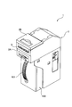
- FIG. 1 shows an example of the banknote identification device which is a paper sheet identification device, and is a perspective view which shows the whole structure.
- the perspective view which shows the state which opened the opening-and-closing member with respect to the main body frame of an apparatus main body.
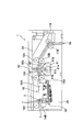
- the right view which showed roughly the conveyance path
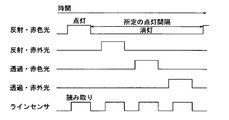
- the timing chart which shows the lighting control of the light emission part in a banknote reading means, and shows the lighting control of the light emission part at the time of reading a banknote.
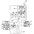
- the block diagram which shows the structure of the control means which controls operation
- FIG. 10B is a diagram for explaining a change in correlation coefficient when the comparison region in FIG. 10A is shifted by one pixel in the vertical and horizontal directions from the array data in FIGS. 8A and 8B.
- FIG. 1 to 3 are diagrams showing an example in which a paper sheet identification device according to the present invention is applied to a banknote identification device.
- FIG. 1 is a perspective view showing the overall configuration
- FIG. 3 are the right view which showed roughly the conveyance path
- the banknote identification device 1 is configured to be incorporated into various gaming machines such as a slot machine, for example, and is provided in the device main body 2 and the device main body 2 to stack and store a large number of banknotes. And a storage unit (storage stacker; safe) 100 that can be used.
- the housing 100 may be detachable from the apparatus main body 2.
- the apparatus main body 2 can be obtained by pulling the handle 101 provided on the front surface in a state where a lock mechanism (not shown) is released. It is possible to remove from.
- the apparatus main body 2 has a main body frame 2A and an opening / closing member 2B configured to be opened and closed with one end portion as a rotation center with respect to the main body frame 2A.
- the main body frame 2 ⁇ / b> A and the opening / closing member 2 ⁇ / b> B when the opening / closing member 2 ⁇ / b> B is closed with respect to the main body frame 2 ⁇ / b> A, a gap in which bills are conveyed to the opposite portions (banknote conveyance path 3) Is formed, and the bill insertion slot 5 is formed on the front exposed side of both so as to coincide with the bill transport path 3.
- the bill insertion slot 5 has a slit-like opening so that it can be inserted into the apparatus main body 2 from the short side of the bill.
- a banknote transport mechanism that transports banknotes along the banknote transport path 3, an insertion detection sensor 7 that detects a banknote inserted into the banknote insertion slot 5, and an insertion detection sensor 7.
- the banknote reading means 8 that is installed on the downstream side of the banknote and reads the information of the banknote in the transported state, and the skew correction mechanism 10 that accurately positions and transports the banknote with respect to the banknote reading means 8 is provided. .
- the banknote conveyance path 3 extends from the banknote insertion slot 5 toward the back side, and a discharge port 3 a for discharging banknotes to the banknote storage unit 100 is formed on the downstream side.
- the banknote transport mechanism is a mechanism that enables the banknote inserted from the banknote insertion slot 5 to be transported along the insertion direction, and allows the banknote in the inserted state to be fed back toward the banknote insertion slot 5.
- the banknote transport mechanism is driven by a motor 13 (see FIG. 5), which is a drive source installed in the apparatus main body 2, and rotated by the motor 13, and is placed in the banknote transport path 3 at predetermined intervals along the banknote transport direction.
- a pair of transport rollers (14A, 14B), (15A, 15B), (16A, 16B), and (17A, 17B) are provided.
- the pair of transport rollers is installed so that a part thereof is exposed in the banknote transport path 3, and transport rollers 14 ⁇ / b> B, 15 ⁇ / b> B, 16 ⁇ / b> B, and 17 ⁇ / b> B, all installed below the banknote transport path 3, are driven by the motor 13.
- the conveying rollers 14A, 15A, 16A, and 17A installed on the upper side are pinch rollers that are driven by these rollers.
- the conveyance roller pair (14A, 14B) that first clamps the banknote inserted from the banknote insertion slot 5 and transports it to the back side is installed at one central position of the banknote transport path 3, as shown in FIG.
- the transport roller pairs (15A, 15B), (16A, 16B), and (17A, 17B) that are sequentially arranged on the downstream side thereof are spaced apart along the width direction of the banknote transport path 3. Two places are installed.
- the upper conveyance roller 14A is in the state spaced apart from the lower conveyance roller 14B.
- the insertion detection sensor 7 detects this insertion, the upper transport roller 14A is driven toward the lower transport roller 14B to sandwich the inserted bill.
- the skew correction mechanism 10 includes a pair of left and right movable pieces 10A (only one side is shown) that performs skew correction, and the pair of left and right movable pieces 10A is driven by driving a motor 40 for the skew correction mechanism. It moves so that it may approach, and the correction process of the skew with respect to a banknote is performed by this.
- the insertion detection sensor 7 generates a detection signal when a banknote inserted into the banknote insertion slot 5 is detected. When this detection signal is generated, the motor 13 is driven to rotate forward to insert a banknote. Transport in the direction.
- the insertion detection sensor 7 of the present embodiment is installed between the transport roller pair (14A, 14B) and the skew correction mechanism 10, and is configured by an optical sensor, for example, a retroreflective photosensor. However, other than that, it may be constituted by a mechanical sensor.
- the bill reading means 8 reads the bill information of the bill conveyed with the skew corrected by the skew correction mechanism 10 and identifies its validity (authenticity).
- the banknote reading means 8 is configured to include a line sensor that performs reading by irradiating light from both sides of a banknote to be conveyed and detecting the transmitted light and reflected light with a light receiving element. Yes.
- the authenticity identification process in the present embodiment uses the above-described bill reading means 8 to irradiate light to the printed portion of the bill to be conveyed and receive the transmitted light and reflected light so as to increase the identification accuracy.
- it is configured to identify whether or not the feature points in the print portion (the feature point area to be identified and the extraction method are arbitrary) match the authentic ones.
- the watermark part formed in the banknote is also made into the identification object area
- the bill information in is converted into a two-dimensional image for authenticity determination. That is, since the watermark portion is a characterized portion as one means for preventing counterfeiting of banknotes, a two-dimensional image is obtained for such a watermark region, and this is used as the watermark of a genuine note banknote. By comparing with partial data, the identification accuracy can be further improved.
- this embodiment focuses on this point, By irradiating the bill with light of different wavelengths (in this embodiment, irradiating red light and infrared light) depending on the light source, and detecting the transmitted light and reflected light, the authenticity of the authenticity is further improved. ing. That is, since red light and infrared light have different wavelengths, if transmitted light data or reflected light data from a plurality of lights having different wavelengths is used for determining the authenticity of a bill, it passes through a specific area between a genuine note and a counterfeit bill. Transmitted light and reflected light reflected from a specific region have properties that the transmittance and the reflectance are different. For this reason, the identification accuracy of the authenticity of a banknote is raised more by using the light source of a some wavelength.
- the wavelength of light to be irradiated for example, visible light or infrared light
- banknote reading means 8 controls the lighting of the light emitting part at a predetermined interval and detects transmitted light and reflected light when the banknote passes by a line sensor, as described later.
- the sensor makes it possible to acquire image data based on a plurality of pieces of pixel information with a predetermined size as one unit.
- the image data acquired by the line sensor is converted into data including color information having brightness for each pixel by a conversion unit described later.
- the color information for each pixel having brightness that is converted by the conversion unit corresponds to a gray value, that is, a density value (luminance value), and is, for example, 1-byte information according to the density value. , 0 to 255 (0: black to 255: white) are assigned to each pixel.
- the authenticity identification process mentioned above it is not limited to the watermark part formed in a banknote, The various area
- an analog waveform can be generated from transmitted light data or reflected light data, and authenticity can be identified by comparing the shapes of the waveforms.
- the bill reading means 8 described above is disposed on the opening / closing member 2B side, and a light emitting unit 80 including a first light emitting unit 80a capable of irradiating infrared light and red light on the upper side of a conveyed bill, and a main body frame And a light emitting / receiving unit 81 disposed on the 2A side.
- the light receiving / emitting unit 81 is disposed adjacent to both sides of the light receiving unit 81a in the bill conveyance direction, and includes a light receiving unit 81a including a light receiving sensor facing the first light emitting unit 80a so as to sandwich the bill. And a second light emitting portion 81b that can emit light.
- the first light emitting unit 80a disposed opposite to the light receiving unit 81a functions as a light source for transmission.
- the first light emitting unit 80a is formed of a rectangular rod-shaped body made of synthetic resin that emits light from the LED element 80b attached to one end through a light guide 80c provided inside.
- the 1st light emission part of such composition is arranged in the shape of a line in parallel with light reception part 81a (light reception sensor), and is simple composition, and with respect to the whole conveyance path width direction range of the bill conveyed It becomes possible to irradiate uniformly as a whole.
- the light receiving unit 81a of the light receiving / emitting unit 81 is formed in a strip shape extending in the crossing direction with respect to the banknote transport path 3 and having a width that does not affect the sensitivity of a light receiving sensor (not shown) provided in the light receiving unit 81a. It is formed into a thin plate shape.
- the light receiving sensor is provided with a plurality of CCDs (Charge Coupled Devices) in the center of the light receiving portion 81a in the thickness direction, and condenses transmitted light and reflected light above the CCD.
- the line sensor is configured as a so-called line sensor in which a green lens array 81c is arranged in a line shape.
- the transmitted light or reflected light of infrared light or red light from the first light emitting unit 80a or the second light emitting unit 81b irradiated toward the bill to be identified is received, and the brightness is received as received light data. It is possible to generate grayscale data (pixel data including brightness information) corresponding to the above and a two-dimensional image from this grayscale data.
- the second light emitting unit 81b of the light emitting / receiving unit 81 functions as a light source for reflection.
- the second light emitting unit 81b is made of a synthetic resin that can uniformly irradiate light from the LED element 81d attached to one end through the light guide 81e provided inside. It is composed of a rectangular bar.
- the second light emitting unit 81b is also configured to be arranged in a line parallel to the light receiving unit 81a (line sensor).
- the second light emitting unit 81b can irradiate light toward the banknote at an elevation angle of 45 degrees, for example, and is disposed so that reflected light from the banknote is received by the light receiving unit 81a.
- the light emitted from the second light emitting unit 81b is incident on the light receiving unit 81a at 45 degrees, but the incident angle is not limited to 45 degrees, and there is no shading with respect to the surface of the banknote. If light can be irradiated uniformly, the installation state can be appropriately set. For this reason, about the arrangement
- the second light emitting unit 81b is installed on both sides with the light receiving unit 81a in between so that light is irradiated from both sides at an incident angle of 45 degrees. This is because if there are scratches or folds on the banknote surface, and light is irradiated only from one side to the irregularities generated on these scratches or folds, the irregularities will inevitably become blocked by light. A spot may occur. For this reason, by irradiating light from both sides, it is possible to prevent shadows from being formed in the uneven portions, and to obtain image data with higher accuracy than irradiation from one side. Of course, about the 2nd light emission part 81b, the structure installed only in one side may be sufficient.
- the configurations and arrangements of the light emitting unit 80 and the light emitting / receiving unit 81 described above are not limited to the present embodiment, and can be appropriately modified.
- the lighting is controlled at predetermined intervals. That is, the four light sources including the light source for transmitting red light and infrared light and the light source for reflecting red light and infrared light in the first light emitting unit 80a and the second light emitting unit 81b are arranged at a predetermined interval (predetermined). The lighting control is repeated so that two or more light sources are not turned on at the same time without repeating the phases of the light sources.
- the other three light sources are controlled to be turned off.
- the light of each light source is detected at regular intervals, and the transmitted light and reflected light of red light, the transmitted light and reflected light of infrared light are used. It is possible to read an image made up of grayscale data in the banknote print area, and to measure the print length on both sides. In this case, the resolution can be increased by controlling the lighting interval to be short.
- the banknote identified as authentic in the banknote reading means 8 comprised as mentioned above is conveyed by the banknote conveyance mechanism to the banknote accommodating part 100 mentioned above via the discharge port 3a of the banknote conveying path 3, and in a banknote accommodating part. Are sequentially stacked and accommodated. Moreover, the banknote identified as a fake is returned to the banknote insertion slot 5 side by the reverse rotation of the banknote transport mechanism, and discharged from the banknote insertion slot 5.
- control means 200 for controlling the operation of the banknote identification device 1 described above will be described with reference to the block diagram of FIG.
- the control means 200 shown in the block diagram of FIG. 5 includes a control board 210 that controls the operation of each driving device described above. On the control board 210, the driving of each driving device is controlled and banknote identification is performed.
- a CPU Central Processing Unit
- ROM Read Only Memory
- RAM Random Access Memory
- the ROM 222 stores permanent data such as operation programs of various driving devices such as the bill conveyance mechanism motor 13 and the skew correction mechanism motor 40, and various programs such as an authenticity determination program in the authenticity determination unit 230. Has been.
- the CPU 220 operates according to the program stored in the ROM 222, inputs / outputs signals to / from the various driving devices described above via the I / O port 240, and performs overall operation control of the bill recognition device. . That is, the CPU 220 is connected to driving devices such as the bill transport mechanism motor 13 and the skew correction mechanism motor 40 via the I / O port 240, and these driving devices are stored in the ROM 222. The operation is controlled by a control signal from the CPU 220 in accordance with the operation program. Further, a detection signal from the insertion detection sensor 7 is input to the CPU 220 via the I / O port 240. Based on this detection signal, drive control of the drive device described above is performed. .
- a detection signal based on transmitted light or reflected light of the light irradiated on the banknote is input to the CPU 220 from the light receiving unit 81a in the banknote reading means 8 described above via the I / O port 240. ing.
- the RAM 224 temporarily stores data and programs used when the CPU 220 operates, and acquires and temporarily stores bill received light data (image data composed of a plurality of pixels). I have.
- the authenticity determination unit 230 has a function of performing authenticity identification processing on the conveyed banknote and identifying the authenticity of the banknote.
- the authenticity determination unit 230 relates to the received light data of the banknote stored in the RAM 224, and the conversion unit 232 converts the pixel information including brightness color information (density value) for each pixel, and the authentic banknote.
- an identification processing unit 235 that performs authentication processing of authenticity.
- the reference data storage unit 233 stores the image data (standard image) of the watermark portion with respect to the genuine banknote used when performing the authenticity identification process.
- this standard image corresponds to image data of a large number of pixels obtained by irradiating light to a watermark image area of a genuine banknote and receiving the transmitted light.
- a predetermined parameter (xStart, yStart, xsize, ysize) and stored.
- the above-described reference data (including the standard image) is stored in the dedicated reference data storage unit 233, but may be stored in the ROM 222 described above. Further, the reference data (standard data) that is referred to during authenticity identification processing may be stored in advance in the reference data storage unit 233. For example, a predetermined number of genuine bills are conveyed through the bill conveyance mechanism. However, the light receiving data may be acquired, an average value may be calculated from the obtained data of many genuine bills, and this may be stored as reference data.
- the CPU 220 is connected to the first light emitting unit 80 a and the second light emitting unit 81 b in the bill reading means 8 described above via the I / O port 240.
- the first light emitting unit 80 a and the second light emitting unit 81 b are controlled to be turned on and off by the control signal from the CPU 220 via the light emission control circuit 260 in accordance with the operation program stored in the ROM 222 described above.
- two-dimensional image information can be acquired from a large number of pixel information. Then, for example, based on the brightness information of each pixel converted by the conversion unit 232, a target area for identifying authenticity is extracted, and the extracted image information is compared with reference data. The authenticity is identified with.
- the area to be authentically identified is a portion that is difficult to counterfeit within the printed area of the banknote, and in the present invention, a two-dimensional image of the area of the watermark area of the banknote is extracted, By comparing this with the reference data, the authentication process is performed.
- the watermark portion of the banknote has a phenomenon in which light and dark are reversed when viewed with transmitted light and reflected light.
- the present invention pays attention to such a phenomenon, and the authenticity of the watermark portion is identified by the light receiving portion 81a installed only on one side of the bill to be conveyed.
- the processing step of identifying authenticity using a watermark portion Uses a light source that emits infrared light for transmission and infrared light for reflection among a plurality of light sources. That is, this makes it possible to further improve the accuracy of authenticity identification.
- the density value for each pixel obtained by the reflected light of the watermark image in the conversion unit 232 is the density value for each pixel by the transmitted light obtained at the same position (this density value is stored as reference data as standard data). (Previously stored in the unit 233). For this reason, when the correlation coefficient R is calculated from the density values of both pixels, the correlation coefficient (negative) is shifted to the minus side within the range of ⁇ 1 ⁇ R ⁇ 1 that can be taken by the correlation coefficient R. Correlation coefficient). Although the ideal value is considered to be a correlation coefficient of -1, it is actually a value larger than -1 due to the effects of banknote defacement, wrinkles, and watermark shift.
- the authenticity of the watermark formed on the banknote can also be identified by the light receiving unit 81a installed on one side.
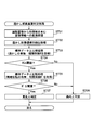
- the banknote reading means 8 first reads the conveyed banknote, and the conversion unit 232 converts the read image into pixel information including color information (ST01).
- the bill reading means 8 irradiates light (red light, infrared light) from the first light emitting portion 80a and the second light emitting portion 81b to the bill conveyed by the bill conveying mechanism, The transmitted light and the reflected light are received by the light receiving unit (line sensor) 81a, and the bill is read.
- the light receiving unit (line sensor) 81a the light receiving unit
- Image data composed of a large number of pixels is stored in storage means such as the RAM 224. Then, the image data composed of a large number of pixels stored here is converted into color information (brightness values from 0 to 255 (0: black to 255 depending on the density value)) for each pixel by the conversion unit 232. : White) is converted into information including the assigned color information).
- a watermark image region is extracted from the pixel information thus converted (ST02). For example, when a banknote is transported, the density value of the pixel information increases (turns white) at the stage of transition from the print area to the watermark image area, so that the displacement position is detected by setting a threshold value. This makes it possible to extract a watermark image area.
- the watermark image area can be extracted by various methods based on the obtained image information or the converted image information.
- the irradiation light used to extract the watermark image is one of a plurality of light sources, one of transmitted red light and infrared light, and one of reflected light red light and infrared light (in combination). Good) is used.
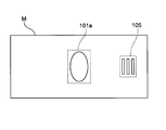
- the identification processing unit 235 extracts standard data (standard data regarding the watermark image) stored in advance in the reference data storage unit 233 using the above-described parameters, and this is reflected by the conversion unit 232. Comparison processing is performed with image data based on light (ST03). In this case, as shown in FIG. 7, for example, if the standard image regarding the banknote M is stored in the reference data storage unit 233, the extracted standard data is the watermark area 101a or the page using the above parameters. A two-dimensional image of the mark formation area 105 is obtained.
- the above-described comparison process in ST03 is a process for determining the presence or absence of a watermark, and includes image information of a watermark area by transmitted light acquired from a conveyed banknote and a watermark of a standard image.
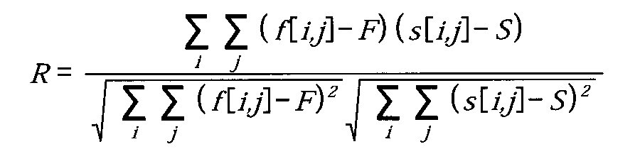
- the authenticity of the conveyed banknote is identified by deriving the correlation coefficient R shown in the following expression 1 with the image information by the transmitted light of the region.
- [i, j] corresponds to the coordinates of the watermark formation area of the banknote, and the two-dimensional image of the acquired data from the banknote to be identified in the banknote coordinates [i, j].
- the density value is f [i, j]
- the density value in the standard data is s [i, j]
- the average density in the acquired data is F
- the average density value in the reference data is S.
- the correlation coefficient R derived from the above equation 1 takes values from ⁇ 1 to +1, and the closer to +1 (the higher the correlation coefficient) is, the higher the similarity is. In this case, if no watermark is formed on the conveyed banknote, there is no correlation between them (the correlation coefficient approaches 0), so a predetermined threshold is set for the derived correlation coefficient R. On the other hand, if the correlation coefficient R is lower than the threshold value, it is determined that the watermark is not formed (ST04; No, ST08).
- the second comparison process is subsequently executed (ST05).
- this comparison process uses image data obtained by transmitted light and reflected light (remarkably recognized by near-infrared light, so image data from a reflected light source that irradiates infrared light among light sources is used. Is a process of identifying authenticity using the relationship because the image is inverted, and the image information of the watermark area by the reflected light acquired from the conveyed banknote and the watermark area of the standard image The authenticity of the bill to be conveyed is identified by deriving the correlation coefficient R ′ represented by the above-described equation 1 with the image information by the transmitted light.
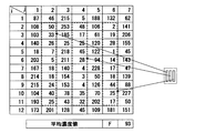
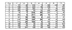
- FIG. 8A is image data based on reflected light (reflected data based on near-infrared light) in the insertion mark forming area 105 of the bill to be conveyed, and shows pixel information including color information converted by the conversion unit 232. Yes.
- 12 pixels are extracted in one direction (vertical direction) in the insertion mark formation region 105, and 7 pixels are extracted in the transport direction (horizontal direction).
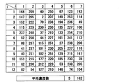
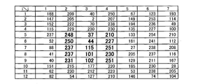
- FIG. 8B shows standard data in the insertion mark formation area stored in advance in the reference data storage unit 233, and shows image data by transmitted light at the same position as FIG. 8A.
- both image data have a relationship in which light and dark are reversed. That is, in the conversion unit 232, the density value for each pixel obtained by the reflected light of the watermark image is in a relationship opposite to the density value for each pixel by the transmitted light obtained at the same position.
- the correlation coefficient R ′ is calculated from the density value, the correlation coefficient shifted to the negative side within the range of ⁇ 1 ⁇ R ′ ⁇ 1, which can be taken by the correlation coefficient R ′ (negative correlation) Number).
- the pixels of the acquired watermark image are set so as to correspond to the pixel positions of the standard image of the reference banknote. It is preferable to perform position correction (referred to as neighborhood search) by moving the position, and extract the place where the absolute value of the correlation coefficient is the highest between the two to identify the authenticity.
- position correction referred to as neighborhood search
- the image data of the obtained watermark area is displaced by a predetermined number of pixels vertically and horizontally as indicated by arrows (in the figure, image data
- the position P1 of the characteristic image 110 is moved to P2 as the image 110 ′ when the pixel is shifted upward by 3 pixels as a whole).
- the correlation coefficient is calculated. That is, when performing such position correction, for example, if a search is executed with a shift of ⁇ 4 pixels in the vertical and horizontal directions, 81 correlation coefficients are derived in total as a neighborhood search. Then, each of the derived correlation coefficients is sequentially stored in the RAM 224, and finally all correlation coefficients are calculated, and then the position where the absolute value of the correlation coefficient is the highest is determined.
- the identification is made as an identification target.
- the comparison area in the actually measured data in FIG. 10A is compared with the corresponding area in the reference data in FIG. 10B.
- the comparison area of FIG. 10A is displaced one pixel up and down and left and right, and the correlation coefficient is calculated by (Equation 1) described above at each displaced position.
- the present embodiment by acquiring the information (two-dimensional image information) of the watermark image for preventing counterfeiting in the banknote and comparing it with the watermark image information (standard image) serving as a reference, Accuracy can be improved.
- the authentication can be performed only by the light receiving unit 81a installed on one side of the bill to be conveyed, the cost does not increase.
- the banknote identification device is configured so that it can process multiple types of banknotes
- the above-described watermark portion identification processing step as described above can be performed using the banknote denomination (which face value of which issue series in which country). ) Is performed after the identification process is completed. For this reason, since the position where the watermark is formed is determined for each denomination, the standard data may be stored accordingly.
- the standard data based on the transmitted light in the watermark area is stored in advance in the reference data storage unit 233.
- the data based on the transmitted light is acquired from the bills being conveyed. You may do it. That is, it is possible to identify the authenticity of the watermark area by acquiring image data of reflected light and transmitted light from the watermark area of the bill to be conveyed and performing the above-described processing.
- the image information of the watermark portion of the banknote to be identified is characterized by identifying authenticity by focusing on the fact that transmitted light and reflected light are inverted in brightness and darkness.
- the configuration is not limited to the above-described embodiment. For this reason, the first comparison process described above may not be performed.
- the authenticity identification method as described above may be any method as long as the above-described method is used as one of the authenticity identification processing by various methods, and further includes other authenticity identification processing. There may be. In this case, the priority order executed with respect to other authenticity identification processing is not limited.
- the above-described configuration of the bill reading means 8 (may be a configuration other than a line sensor) and a mechanism for driving various driving members can be appropriately modified.
- the paper sheet identification device of the above-described embodiment uses this relationship to install light receiving means only on one side of the conveyed paper sheet to identify authenticity.
- the conversion unit since the density value for each pixel obtained by the reflected light of the watermark image is opposite to the density value for each pixel by the transmitted light obtained at the same position, a correlation coefficient shifted to the minus side can be obtained within the range of ⁇ 1 ⁇ R ⁇ 1, which is the range that the correlation coefficient R can take (The ideal value is considered to be a correlation coefficient of ⁇ 1, but it is actually a value larger than ⁇ 1 due to the effects of banknote defacement, wrinkles, watermark misalignment, etc.) For this reason, by setting a threshold value that is equal to or less than a predetermined value, it is possible to derive such a contradictory density value between the transmitted light and the reflected light, and the conveyed paper sheet.
- the density value for each pixel by the transmitted light of the watermark image of the reference paper sheet may be acquired by the transmitted light from the actually transported paper sheet, or an identification processing unit as a reference value in advance. It may be stored in the memory.
- the light receiving unit can receive the transmitted light of the watermark image of the conveyed paper sheet
- the identification processing unit includes a density value for each pixel by the transmitted light of the watermark image acquired by the light receiving unit, and The correlation coefficient can be calculated from the density value for each pixel by the transmitted light of the watermark image of the paper sheet as the reference, and the authenticity of the watermark image can be identified based on the correlation coefficient.
- the correlation coefficient from the density value for each pixel by the transmitted light of the watermark image of the conveyed paper sheet and the density value for each pixel by the transmitted light of the watermark image of the reference paper sheet is possible to eliminate paper sheets that are not formed with a watermark pattern.
- the identification processing unit performs position correction by moving the pixel position of the acquired watermark image so as to correspond to the pixel position of the watermark image of the paper sheet as a reference.
- the authenticity can be identified by extracting the place where the absolute value of the correlation coefficient is the highest.
- the light irradiated to the paper sheet can be near infrared light.
- the paper sheet identification method of the above-described embodiment includes reflection of a watermark image formed on a transported paper sheet for each pixel including color information having brightness and having a predetermined size as one unit.
- the correlation coefficient is calculated from the image acquisition step of acquiring light, the density value for each pixel by the reflected light of the watermark image, and the density value for each pixel by the transmitted light of the watermark image of the reference paper sheet And an authenticity identifying step using reflected light for identifying the authenticity of the watermark image based on the correlation coefficient.
- the paper sheet identification method of the above-described embodiment uses this relationship to install light receiving means only on one side of the conveyed paper sheet to identify authenticity.
- the density value for each pixel based on the reflected light of the watermark image is in a relationship with the density value for each pixel based on the transmitted light obtained at the same position.
- the correlation coefficient R is calculated from the density value of each pixel, and a threshold value equal to or less than a predetermined value is set, so that such a contradictory density between the transmitted light and the reflected light.
- the relationship between the values is derived to identify the authenticity of the watermark formed on the paper sheet.
- the density value for each pixel by the reflected light of the watermark image described above is the density for each pixel by the transmitted light obtained at the same position. Since the correlation coefficient is opposite to the value, a correlation coefficient shifted to the minus side can be obtained (the ideal value is considered to be a correlation coefficient of -1, but such as banknote defacement, wrinkles, and watermark misalignment) Due to the influence, the value is actually larger than ⁇ 1), and by setting a threshold value not more than a predetermined value, such a contradictory density value is obtained between the transmitted light and the reflected light.
- the relationship can be derived, and the authenticity of the watermark formed on the paper sheet can be identified by the light receiving means installed on one side of the conveyed paper sheet.
- the density value for each pixel by the transmitted light of the watermark image of the reference paper sheet may be acquired from the transmitted light from the actually transported paper sheet or stored as a reference value in advance. It may be a thing.
- the light receiving unit that receives the reflected light of the watermark image formed on the conveyed paper sheet, and the reflected light of the watermark image received by the light receiving unit is reflected at the brightness level.
- a conversion unit that converts data into each pixel
- a memory for example, ROM, RAM, FPROM, HDD, etc.
- the processor calculates a correlation coefficient corresponding to the pixel position from the converted reflected light data for each pixel converted by the conversion unit and the reference data for each pixel by the transmitted light of the watermark image of the paper sheet used as a reference. It works as possible.
- it since it functions so as to be able to determine whether the absolute value of the correlation coefficient is equal to or greater than a predetermined threshold, the authenticity of the watermark image can be identified based on the determination.
- the light receiving unit may be capable of receiving the transmitted light of the watermark image of the conveyed paper sheet.
- the conversion unit may convert the transmitted light of the watermark image received by the light receiving unit into transmitted light data of a brightness level for each pixel.
- the memory can store the converted transmitted light data converted by the conversion unit in association with the pixel position. Using such data, the processor determines the pixel position from the converted transmitted light data for each pixel converted by the conversion unit and the reference data for each pixel by the transmitted light of the watermark image of the reference paper sheet. Correlation functions to enable calculation of correlation coefficients.
- the processor can function so as to be able to calculate a shift correlation coefficient corresponding to the shifted pixel position from the converted reflected light data and the reference data by shifting the pixel position of the converted reflected light data. Then, in the absolute value of the correlation coefficient before the shift and the absolute value of the shift correlation coefficient, the larger pixel position is used as a comparison pixel position and associated with image data for each pixel for identifying the authenticity of the image. To be stored in the memory.
- This shift can be performed by shifting a predetermined number of pixels (for example, one pixel) from front to back and from side to side with reference to the original image position obtained from the density data of the print area of the banknote. Then, a correlation coefficient is obtained for each shift, and the converted reflected light data or the converted transmitted light data (these are the comparison pixel positions for comparing the shift positions at which the absolute values of the correlation coefficients are maximum) , Mainly in association with digital data).
- the image acquisition step acquires the transmitted light of the watermark image formed on the conveyed paper sheet for each pixel including color information having brightness and having a predetermined size as one unit
- the correlation coefficient is calculated from the density value for each pixel by the transmitted light of the watermark image acquired in the image acquisition process and the density value for each pixel by the transmitted light of the watermark image of the reference paper sheet. It may further include an authenticity identifying step by transmitted light for identifying the authenticity of the watermark image based on the number.
- a correlation is obtained from the density value for each pixel by the transmitted light of the watermark image acquired in the image acquisition step and the density value for each pixel by the transmitted light of the watermark image of the reference paper sheet.
- the watermark image acquired so as to correspond to the pixel position of the watermark image of the paper sheet used as a reference when calculating the correlation coefficient It is possible to identify the authenticity by moving the pixel position and performing position correction and extracting the place where the absolute value of the correlation coefficient is the highest.
- the present invention can be incorporated into various devices for identifying the authenticity of paper sheets other than banknotes, such as gift certificates and coupons, in addition to the above banknotes.
Landscapes
- Physics & Mathematics (AREA)
- Health & Medical Sciences (AREA)
- General Health & Medical Sciences (AREA)
- Toxicology (AREA)
- General Physics & Mathematics (AREA)
- Spectroscopy & Molecular Physics (AREA)
- Engineering & Computer Science (AREA)
- Computer Security & Cryptography (AREA)
- Inspection Of Paper Currency And Valuable Securities (AREA)
Abstract
Description
2 装置本体
3 紙幣搬送路
5 紙幣挿入口
8 紙幣読取手段
10 スキュー補正機構
80 発光ユニット
80a 第1発光部
81 受発光ユニット
81a 受光部
81b 第2発光部
200 制御手段
Claims (10)
- 搬送される紙葉類に形成された透かし画像の反射光を受光する受光手段と、
前記受光手段で受光した透かし画像の反射光を、明るさを有する色情報を含み、所定の大きさを1単位とする画素毎に変換する変換部と、
前記変換部で変換された画素毎の濃度値、及び、基準となる紙葉類の透かし画像の透過光による画素毎の濃度値から相関係数を算出して、その相関係数に基づいて透かし画像の真贋を識別する識別処理部と、を有することを特徴とする紙葉類識別装置。 - 前記受光手段は、前記搬送される紙葉類の透かし画像の透過光を受光可能であり、
前記識別処理部は、受光手段で取得した透かし画像の透過光による画素毎の濃度値、及び、前記基準となる紙葉類の透かし画像の透過光による画素毎の濃度値から相関係数を算出して、その相関係数に基づいて透かし画像の真贋を識別することを特徴とする請求項1に記載の紙葉類識別装置。 - 前記識別処理部は、相関係数を算出する際に、基準となる紙葉類の透かし画像の画素位置に対応するように、取得した透かし画像の画素位置を移動させて位置補正を実行し、相関係数の絶対値が最も高いところを抽出して真贋を識別することを特徴とする請求項1又は2に記載の紙葉類識別装置。
- 前記紙葉類に照射される光は、近赤外光であることを特徴とする請求項1から3のいずれか1項に記載の紙葉類識別装置。
- 明るさを有する色情報を含み、所定の大きさを1単位とする画素毎に、搬送される紙葉類に形成された透かし画像の反射光を取得する画像取得工程と、
前記透かし画像の反射光による画素毎の濃度値、及び、基準となる紙葉類の透かし画像の透過光による画素毎の濃度値から相関係数を算出して、その相関係数に基づいて透かし画像の真贋を識別する反射光による真贋識別工程と、を有することを特徴とする紙葉類識別方法。 - 前記画像取得工程は、明るさを有する色情報を含み、所定の大きさを1単位とする画素毎に、搬送される紙葉類に形成された透かし画像の透過光を取得し、
前記画像取得工程で取得した透かし画像の透過光による画素毎の濃度値、及び、基準となる紙葉類の透かし画像の透過光による画素毎の濃度値から相関係数を算出して、その相関係数に基づいて透かし画像の真贋を識別する透過光による真贋識別工程をさらに有することを特徴とする請求項5に記載の紙葉類識別方法。 - 前記反射光による真贋識別工程、及び透過光による真贋識別工程において、相関係数を算出する際に、基準となる紙葉類の透かし画像の画素位置に対応するように、取得した透かし画像の画素位置を移動させて位置補正を実行し、相関係数の絶対値が最も高いところを抽出して真贋を識別することを特徴とする請求項5又は6に記載の紙葉類識別方法。
- 搬送される紙葉類に形成された透かし画像の反射光を受光する受光部と、
前記受光部で受光した透かし画像の反射光を、明るさレベルの反射光データに画素毎に変換する変換部と、
前記変換部で変換された変換反射光データをその画素位置と関連付けて記憶するメモリと、
演算を行うプロセッサと、を備え、
前記プロセッサは、
前記変換部で変換された画素毎の変換反射光データ及び基準となる紙葉類の透かし画像の透過光による画素毎の基準データから、画素位置に対応させて相関係数を算出可能に機能し、
その相関係数の絶対値が所定の閾値以上であるかを判断可能に機能し、その判断に基づいて透かし画像の真贋を識別する紙葉類識別装置。 - 前記受光部は、前記搬送される紙葉類の透かし画像の透過光を受光可能であり、
前記変換部は、前記受光部で受光した透かし画像の透過光を、明るさレベルの透過光データに画素毎に変換し、
前記メモリは、前記変換部で変換された変換透過光データをその画素位置と関連付けて記憶し、
前記プロセッサは、
前記変換部で変換された画素毎の変換透過光データ及び基準となる紙葉類の透かし画像の透過光による画素毎の基準データから、画素位置に対応させて相関係数を算出可能に機能し、
その相関係数の絶対値が所定の閾値以上であるかを判断可能に機能し、その判断に基づいて透かし画像の真贋を識別する請求項8に記載の紙葉類識別装置。 - 前記プロセッサは、
前記変換反射光データの画素位置をシフトさせて、前記変換反射光データ及び前記基準データから、シフトされた画素位置に対応するシフト相関係数を算出可能に機能し、
シフト前の前記相関係数の絶対値及び前記シフト相関係数の絶対値において、より大きい方の画素位置を比較画素位置とする請求項8又は9に記載の紙葉類識別装置。
Priority Applications (3)
| Application Number | Priority Date | Filing Date | Title |
|---|---|---|---|
| US12/865,794 US8483472B2 (en) | 2008-01-31 | 2009-01-30 | Paper sheet identifying device and paper sheet identifying method |
| AU2009209915A AU2009209915A1 (en) | 2008-01-31 | 2009-01-30 | Paper sheet identifying device and paper sheet identifying method |
| CN2009801035522A CN101933053B (zh) | 2008-01-31 | 2009-01-30 | 纸张类识别装置和纸张类识别方法 |
Applications Claiming Priority (2)
| Application Number | Priority Date | Filing Date | Title |
|---|---|---|---|
| JP2008020515A JP5209982B2 (ja) | 2008-01-31 | 2008-01-31 | 紙葉類識別装置、及び紙葉類識別方法 |
| JP2008-020515 | 2008-01-31 |
Publications (1)
| Publication Number | Publication Date |
|---|---|
| WO2009096553A1 true WO2009096553A1 (ja) | 2009-08-06 |
Family
ID=40912896
Family Applications (1)
| Application Number | Title | Priority Date | Filing Date |
|---|---|---|---|
| PCT/JP2009/051641 Ceased WO2009096553A1 (ja) | 2008-01-31 | 2009-01-30 | 紙葉類識別装置、及び紙葉類識別方法 |
Country Status (5)
| Country | Link |
|---|---|
| US (1) | US8483472B2 (ja) |
| JP (1) | JP5209982B2 (ja) |
| CN (1) | CN101933053B (ja) |
| AU (1) | AU2009209915A1 (ja) |
| WO (1) | WO2009096553A1 (ja) |
Families Citing this family (14)
| Publication number | Priority date | Publication date | Assignee | Title |
|---|---|---|---|---|
| WO2013027848A1 (ja) * | 2011-08-25 | 2013-02-28 | グローリー株式会社 | 紙葉類識別装置、紙葉類分光測定用ライトガイド及びライトガイドケース |
| DE102011082174A1 (de) * | 2011-09-06 | 2013-03-07 | Bundesdruckerei Gmbh | Vorrichtung zum mobilen Erkennen eines Dokumentes |
| CN102509380B (zh) * | 2011-11-09 | 2013-11-06 | 深圳市倍量科技有限公司 | 识别欧元纸币的方法 |
| JP6026194B2 (ja) * | 2012-09-21 | 2016-11-16 | 株式会社東芝 | 紙葉類の再検査装置、紙葉類検査システム、及び紙葉類検査方法 |
| DE102013006925A1 (de) * | 2013-04-22 | 2014-10-23 | Giesecke & Devrient Gmbh | Vorrichtung und Verfahren zur Prüfung von Wertdokumenten, insbesondere Banknoten, sowie Wertdokumentbearbeitungssystem |
| US10347069B2 (en) * | 2013-04-22 | 2019-07-09 | Giesecke+Devrient Currency Technology Gmbh | Apparatus, method and assembly for checking value documents, in particular bank notes, and value-document processing system |
| JP5897090B2 (ja) * | 2013-10-22 | 2016-03-30 | キヤノン・コンポーネンツ株式会社 | イメージセンサユニット、画像読取装置および紙葉類識別装置 |
| JP5833160B2 (ja) * | 2014-03-07 | 2015-12-16 | キヤノン・コンポーネンツ株式会社 | 照明装置および紙葉類識別装置 |
| US9595038B1 (en) * | 2015-05-18 | 2017-03-14 | Amazon Technologies, Inc. | Inventory confirmation |
| CN105844780B (zh) * | 2016-03-18 | 2019-06-28 | 光荣电子工业(苏州)有限公司 | 纸张判别装置、校正信息设定方法、以及纸张判别方法 |
| CN105957237B (zh) * | 2016-04-22 | 2019-02-01 | 深圳怡化电脑股份有限公司 | 一种纸币的版本识别方法和装置 |
| JP6790605B2 (ja) * | 2016-09-01 | 2020-11-25 | 富士電機株式会社 | 紙幣識別装置 |
| CN106875545B (zh) * | 2017-03-01 | 2019-12-10 | 深圳怡化电脑股份有限公司 | 一种纸币的鉴别方法及装置 |
| JP7126016B1 (ja) * | 2021-08-04 | 2022-08-25 | 日本金銭機械株式会社 | 紙葉搬送装置、及び紙葉取扱装置 |
Citations (3)
| Publication number | Priority date | Publication date | Assignee | Title |
|---|---|---|---|---|
| JPH08221632A (ja) * | 1995-02-20 | 1996-08-30 | Oki Electric Ind Co Ltd | 印刷パターンの真偽判別方法 |
| JP2003288627A (ja) * | 2002-03-28 | 2003-10-10 | Toshiba Corp | 紙葉類判別方法および紙葉類判別装置 |
| JP2005321880A (ja) * | 2004-05-06 | 2005-11-17 | Nippon Conlux Co Ltd | 紙葉類識別装置および方法 |
Family Cites Families (8)
| Publication number | Priority date | Publication date | Assignee | Title |
|---|---|---|---|---|
| US7089420B1 (en) * | 2000-05-24 | 2006-08-08 | Tracer Detection Technology Corp. | Authentication method and system |
| JP2004326547A (ja) * | 2003-04-25 | 2004-11-18 | Nippon Conlux Co Ltd | 紙葉類識別装置および方法 |
| JP4073907B2 (ja) * | 2004-11-16 | 2008-04-09 | 株式会社日本コンラックス | 紙葉類識別装置 |
| JP4915053B2 (ja) | 2005-04-01 | 2012-04-11 | シンフォニアテクノロジー株式会社 | 紙葉類鑑別装置 |
| JP4522952B2 (ja) * | 2006-01-18 | 2010-08-11 | 三菱電機株式会社 | 画像読取装置 |
| JP5196725B2 (ja) * | 2006-02-09 | 2013-05-15 | 株式会社 ソキア・トプコン | 測量機の自動視準装置 |
| JP5137602B2 (ja) * | 2008-01-31 | 2013-02-06 | 株式会社ユニバーサルエンターテインメント | 紙葉類識別装置、及び紙葉類識別方法 |
| JP5184157B2 (ja) * | 2008-03-14 | 2013-04-17 | 株式会社ユニバーサルエンターテインメント | 紙葉類識別装置、及び紙葉類識別方法 |
-
2008
- 2008-01-31 JP JP2008020515A patent/JP5209982B2/ja active Active
-
2009
- 2009-01-30 US US12/865,794 patent/US8483472B2/en active Active
- 2009-01-30 CN CN2009801035522A patent/CN101933053B/zh active Active
- 2009-01-30 AU AU2009209915A patent/AU2009209915A1/en not_active Abandoned
- 2009-01-30 WO PCT/JP2009/051641 patent/WO2009096553A1/ja not_active Ceased
Patent Citations (3)
| Publication number | Priority date | Publication date | Assignee | Title |
|---|---|---|---|---|
| JPH08221632A (ja) * | 1995-02-20 | 1996-08-30 | Oki Electric Ind Co Ltd | 印刷パターンの真偽判別方法 |
| JP2003288627A (ja) * | 2002-03-28 | 2003-10-10 | Toshiba Corp | 紙葉類判別方法および紙葉類判別装置 |
| JP2005321880A (ja) * | 2004-05-06 | 2005-11-17 | Nippon Conlux Co Ltd | 紙葉類識別装置および方法 |
Also Published As
| Publication number | Publication date |
|---|---|
| JP5209982B2 (ja) | 2013-06-12 |
| US8483472B2 (en) | 2013-07-09 |
| CN101933053A (zh) | 2010-12-29 |
| CN101933053B (zh) | 2013-02-13 |
| US20100329507A1 (en) | 2010-12-30 |
| AU2009209915A1 (en) | 2009-08-06 |
| JP2009181398A (ja) | 2009-08-13 |
Similar Documents
| Publication | Publication Date | Title |
|---|---|---|
| JP5209982B2 (ja) | 紙葉類識別装置、及び紙葉類識別方法 | |
| JP5137602B2 (ja) | 紙葉類識別装置、及び紙葉類識別方法 | |
| JP5121477B2 (ja) | 紙幣処理装置及び真贋判定方法 | |
| JP5389641B2 (ja) | 紙幣処理装置及び真贋判定処理方法 | |
| JP5317263B2 (ja) | 紙葉類処理装置 | |
| WO2007108376A1 (ja) | 紙幣の真贋判定方法、及び紙幣の真贋判定装置 | |
| JP5184157B2 (ja) | 紙葉類識別装置、及び紙葉類識別方法 | |
| JP5202160B2 (ja) | 紙葉類処理装置 | |
| JP5210067B2 (ja) | 紙葉類処理装置 | |
| JP5210012B2 (ja) | 紙葉類処理装置 | |
| EP3598401A1 (en) | Paper sheet detection device, paper sheet processing apparatus, and paper sheet detection method | |
| US8522949B2 (en) | Paper sheet processing apparatus | |
| WO2009116375A1 (ja) | 紙葉類処理装置 | |
| JP2009020707A (ja) | 紙葉類識別装置 | |
| JP2007213210A (ja) | 紙葉類鑑別装置 |
Legal Events
| Date | Code | Title | Description |
|---|---|---|---|
| WWE | Wipo information: entry into national phase |
Ref document number: 200980103552.2 Country of ref document: CN |
|
| 121 | Ep: the epo has been informed by wipo that ep was designated in this application |
Ref document number: 09705998 Country of ref document: EP Kind code of ref document: A1 |
|
| WWE | Wipo information: entry into national phase |
Ref document number: 12865794 Country of ref document: US |
|
| NENP | Non-entry into the national phase |
Ref country code: DE |
|
| ENP | Entry into the national phase |
Ref document number: 2009209915 Country of ref document: AU Date of ref document: 20090130 Kind code of ref document: A |
|
| 122 | Ep: pct application non-entry in european phase |
Ref document number: 09705998 Country of ref document: EP Kind code of ref document: A1 |