WO2009090868A1 - 3d映像が記録された記録媒体、3d映像を記録する記録装置、並びに3d映像を再生する再生装置及び再生方法 - Google Patents
3d映像が記録された記録媒体、3d映像を記録する記録装置、並びに3d映像を再生する再生装置及び再生方法 Download PDFInfo
- Publication number
- WO2009090868A1 WO2009090868A1 PCT/JP2009/000109 JP2009000109W WO2009090868A1 WO 2009090868 A1 WO2009090868 A1 WO 2009090868A1 JP 2009000109 W JP2009000109 W JP 2009000109W WO 2009090868 A1 WO2009090868 A1 WO 2009090868A1
- Authority
- WO
- WIPO (PCT)
- Prior art keywords
- pictures
- group
- eye
- video
- picture
- Prior art date
Links
- 238000000034 method Methods 0.000 title claims description 34
- 238000010586 diagram Methods 0.000 description 28
- 238000012545 processing Methods 0.000 description 23
- 239000011521 glass Substances 0.000 description 17
- 239000004973 liquid crystal related substance Substances 0.000 description 13
- 210000003128 head Anatomy 0.000 description 11
- 238000000926 separation method Methods 0.000 description 9
- 230000006835 compression Effects 0.000 description 6
- 238000007906 compression Methods 0.000 description 6
- 230000002452 interceptive effect Effects 0.000 description 6
- 230000004044 response Effects 0.000 description 6
- 238000005516 engineering process Methods 0.000 description 5
- 238000004519 manufacturing process Methods 0.000 description 5
- 230000004048 modification Effects 0.000 description 5
- 238000012986 modification Methods 0.000 description 5
- 239000000463 material Substances 0.000 description 4
- 230000001360 synchronised effect Effects 0.000 description 4
- 102100037812 Medium-wave-sensitive opsin 1 Human genes 0.000 description 3
- 210000004556 brain Anatomy 0.000 description 3
- 238000001093 holography Methods 0.000 description 3
- 230000008569 process Effects 0.000 description 3
- 230000008901 benefit Effects 0.000 description 2
- 238000005520 cutting process Methods 0.000 description 2
- 230000000694 effects Effects 0.000 description 2
- 230000006870 function Effects 0.000 description 2
- 230000004807 localization Effects 0.000 description 2
- PWPJGUXAGUPAHP-UHFFFAOYSA-N lufenuron Chemical compound C1=C(Cl)C(OC(F)(F)C(C(F)(F)F)F)=CC(Cl)=C1NC(=O)NC(=O)C1=C(F)C=CC=C1F PWPJGUXAGUPAHP-UHFFFAOYSA-N 0.000 description 2
- 230000003287 optical effect Effects 0.000 description 2
- 230000008929 regeneration Effects 0.000 description 2
- 238000011069 regeneration method Methods 0.000 description 2
- 238000003860 storage Methods 0.000 description 2
- 239000013589 supplement Substances 0.000 description 2
- 230000007704 transition Effects 0.000 description 2
- 206010047571 Visual impairment Diseases 0.000 description 1
- 230000009118 appropriate response Effects 0.000 description 1
- 230000005540 biological transmission Effects 0.000 description 1
- 230000008859 change Effects 0.000 description 1
- 230000003247 decreasing effect Effects 0.000 description 1
- 238000009826 distribution Methods 0.000 description 1
- 239000000284 extract Substances 0.000 description 1
- 230000009191 jumping Effects 0.000 description 1
- 230000007246 mechanism Effects 0.000 description 1
- 238000001094 photothermal spectroscopy Methods 0.000 description 1
- 239000007787 solid Substances 0.000 description 1
- 230000002194 synthesizing effect Effects 0.000 description 1
- 230000002123 temporal effect Effects 0.000 description 1
- 238000012546 transfer Methods 0.000 description 1
- 238000012800 visualization Methods 0.000 description 1
Images


Classifications
-
- H—ELECTRICITY
- H04—ELECTRIC COMMUNICATION TECHNIQUE
- H04N—PICTORIAL COMMUNICATION, e.g. TELEVISION
- H04N9/00—Details of colour television systems
- H04N9/79—Processing of colour television signals in connection with recording
- H04N9/80—Transformation of the television signal for recording, e.g. modulation, frequency changing; Inverse transformation for playback
- H04N9/804—Transformation of the television signal for recording, e.g. modulation, frequency changing; Inverse transformation for playback involving pulse code modulation of the colour picture signal components
- H04N9/8042—Transformation of the television signal for recording, e.g. modulation, frequency changing; Inverse transformation for playback involving pulse code modulation of the colour picture signal components involving data reduction
-
- G—PHYSICS
- G11—INFORMATION STORAGE
- G11B—INFORMATION STORAGE BASED ON RELATIVE MOVEMENT BETWEEN RECORD CARRIER AND TRANSDUCER
- G11B20/00—Signal processing not specific to the method of recording or reproducing; Circuits therefor
- G11B20/10—Digital recording or reproducing
- G11B20/12—Formatting, e.g. arrangement of data block or words on the record carriers
-
- G—PHYSICS
- G11—INFORMATION STORAGE
- G11B—INFORMATION STORAGE BASED ON RELATIVE MOVEMENT BETWEEN RECORD CARRIER AND TRANSDUCER
- G11B20/00—Signal processing not specific to the method of recording or reproducing; Circuits therefor
- G11B20/10—Digital recording or reproducing
-
- G—PHYSICS
- G11—INFORMATION STORAGE
- G11B—INFORMATION STORAGE BASED ON RELATIVE MOVEMENT BETWEEN RECORD CARRIER AND TRANSDUCER
- G11B27/00—Editing; Indexing; Addressing; Timing or synchronising; Monitoring; Measuring tape travel
- G11B27/10—Indexing; Addressing; Timing or synchronising; Measuring tape travel
- G11B27/19—Indexing; Addressing; Timing or synchronising; Measuring tape travel by using information detectable on the record carrier
- G11B27/28—Indexing; Addressing; Timing or synchronising; Measuring tape travel by using information detectable on the record carrier by using information signals recorded by the same method as the main recording
- G11B27/30—Indexing; Addressing; Timing or synchronising; Measuring tape travel by using information detectable on the record carrier by using information signals recorded by the same method as the main recording on the same track as the main recording
- G11B27/3027—Indexing; Addressing; Timing or synchronising; Measuring tape travel by using information detectable on the record carrier by using information signals recorded by the same method as the main recording on the same track as the main recording used signal is digitally coded
-
- G—PHYSICS
- G11—INFORMATION STORAGE
- G11B—INFORMATION STORAGE BASED ON RELATIVE MOVEMENT BETWEEN RECORD CARRIER AND TRANSDUCER
- G11B27/00—Editing; Indexing; Addressing; Timing or synchronising; Monitoring; Measuring tape travel
- G11B27/10—Indexing; Addressing; Timing or synchronising; Measuring tape travel
- G11B27/19—Indexing; Addressing; Timing or synchronising; Measuring tape travel by using information detectable on the record carrier
- G11B27/28—Indexing; Addressing; Timing or synchronising; Measuring tape travel by using information detectable on the record carrier by using information signals recorded by the same method as the main recording
- G11B27/32—Indexing; Addressing; Timing or synchronising; Measuring tape travel by using information detectable on the record carrier by using information signals recorded by the same method as the main recording on separate auxiliary tracks of the same or an auxiliary record carrier
- G11B27/327—Table of contents
- G11B27/329—Table of contents on a disc [VTOC]
-
- H—ELECTRICITY
- H04—ELECTRIC COMMUNICATION TECHNIQUE
- H04N—PICTORIAL COMMUNICATION, e.g. TELEVISION
- H04N13/00—Stereoscopic video systems; Multi-view video systems; Details thereof
- H04N13/10—Processing, recording or transmission of stereoscopic or multi-view image signals
- H04N13/106—Processing image signals
- H04N13/156—Mixing image signals
-
- H—ELECTRICITY
- H04—ELECTRIC COMMUNICATION TECHNIQUE
- H04N—PICTORIAL COMMUNICATION, e.g. TELEVISION
- H04N13/00—Stereoscopic video systems; Multi-view video systems; Details thereof
- H04N13/10—Processing, recording or transmission of stereoscopic or multi-view image signals
- H04N13/189—Recording image signals; Reproducing recorded image signals
-
- H—ELECTRICITY
- H04—ELECTRIC COMMUNICATION TECHNIQUE
- H04N—PICTORIAL COMMUNICATION, e.g. TELEVISION
- H04N13/00—Stereoscopic video systems; Multi-view video systems; Details thereof
- H04N13/10—Processing, recording or transmission of stereoscopic or multi-view image signals
- H04N13/194—Transmission of image signals
-
- H—ELECTRICITY
- H04—ELECTRIC COMMUNICATION TECHNIQUE
- H04N—PICTORIAL COMMUNICATION, e.g. TELEVISION
- H04N19/00—Methods or arrangements for coding, decoding, compressing or decompressing digital video signals
- H04N19/10—Methods or arrangements for coding, decoding, compressing or decompressing digital video signals using adaptive coding
- H04N19/102—Methods or arrangements for coding, decoding, compressing or decompressing digital video signals using adaptive coding characterised by the element, parameter or selection affected or controlled by the adaptive coding
- H04N19/103—Selection of coding mode or of prediction mode
- H04N19/114—Adapting the group of pictures [GOP] structure, e.g. number of B-frames between two anchor frames
-
- H—ELECTRICITY
- H04—ELECTRIC COMMUNICATION TECHNIQUE
- H04N—PICTORIAL COMMUNICATION, e.g. TELEVISION
- H04N19/00—Methods or arrangements for coding, decoding, compressing or decompressing digital video signals
- H04N19/10—Methods or arrangements for coding, decoding, compressing or decompressing digital video signals using adaptive coding
- H04N19/134—Methods or arrangements for coding, decoding, compressing or decompressing digital video signals using adaptive coding characterised by the element, parameter or criterion affecting or controlling the adaptive coding
- H04N19/136—Incoming video signal characteristics or properties
-
- H—ELECTRICITY
- H04—ELECTRIC COMMUNICATION TECHNIQUE
- H04N—PICTORIAL COMMUNICATION, e.g. TELEVISION
- H04N19/00—Methods or arrangements for coding, decoding, compressing or decompressing digital video signals
- H04N19/10—Methods or arrangements for coding, decoding, compressing or decompressing digital video signals using adaptive coding
- H04N19/169—Methods or arrangements for coding, decoding, compressing or decompressing digital video signals using adaptive coding characterised by the coding unit, i.e. the structural portion or semantic portion of the video signal being the object or the subject of the adaptive coding
- H04N19/188—Methods or arrangements for coding, decoding, compressing or decompressing digital video signals using adaptive coding characterised by the coding unit, i.e. the structural portion or semantic portion of the video signal being the object or the subject of the adaptive coding the unit being a video data packet, e.g. a network abstraction layer [NAL] unit
-
- H—ELECTRICITY
- H04—ELECTRIC COMMUNICATION TECHNIQUE
- H04N—PICTORIAL COMMUNICATION, e.g. TELEVISION
- H04N19/00—Methods or arrangements for coding, decoding, compressing or decompressing digital video signals
- H04N19/50—Methods or arrangements for coding, decoding, compressing or decompressing digital video signals using predictive coding
- H04N19/597—Methods or arrangements for coding, decoding, compressing or decompressing digital video signals using predictive coding specially adapted for multi-view video sequence encoding
-
- H—ELECTRICITY
- H04—ELECTRIC COMMUNICATION TECHNIQUE
- H04N—PICTORIAL COMMUNICATION, e.g. TELEVISION
- H04N21/00—Selective content distribution, e.g. interactive television or video on demand [VOD]
- H04N21/20—Servers specifically adapted for the distribution of content, e.g. VOD servers; Operations thereof
- H04N21/23—Processing of content or additional data; Elementary server operations; Server middleware
- H04N21/234—Processing of video elementary streams, e.g. splicing of video streams or manipulating encoded video stream scene graphs
- H04N21/2343—Processing of video elementary streams, e.g. splicing of video streams or manipulating encoded video stream scene graphs involving reformatting operations of video signals for distribution or compliance with end-user requests or end-user device requirements
- H04N21/23439—Processing of video elementary streams, e.g. splicing of video streams or manipulating encoded video stream scene graphs involving reformatting operations of video signals for distribution or compliance with end-user requests or end-user device requirements for generating different versions
-
- H—ELECTRICITY
- H04—ELECTRIC COMMUNICATION TECHNIQUE
- H04N—PICTORIAL COMMUNICATION, e.g. TELEVISION
- H04N21/00—Selective content distribution, e.g. interactive television or video on demand [VOD]
- H04N21/20—Servers specifically adapted for the distribution of content, e.g. VOD servers; Operations thereof
- H04N21/23—Processing of content or additional data; Elementary server operations; Server middleware
- H04N21/236—Assembling of a multiplex stream, e.g. transport stream, by combining a video stream with other content or additional data, e.g. inserting a URL [Uniform Resource Locator] into a video stream, multiplexing software data into a video stream; Remultiplexing of multiplex streams; Insertion of stuffing bits into the multiplex stream, e.g. to obtain a constant bit-rate; Assembling of a packetised elementary stream
- H04N21/2368—Multiplexing of audio and video streams
-
- H—ELECTRICITY
- H04—ELECTRIC COMMUNICATION TECHNIQUE
- H04N—PICTORIAL COMMUNICATION, e.g. TELEVISION
- H04N21/00—Selective content distribution, e.g. interactive television or video on demand [VOD]
- H04N21/20—Servers specifically adapted for the distribution of content, e.g. VOD servers; Operations thereof
- H04N21/25—Management operations performed by the server for facilitating the content distribution or administrating data related to end-users or client devices, e.g. end-user or client device authentication, learning user preferences for recommending movies
- H04N21/266—Channel or content management, e.g. generation and management of keys and entitlement messages in a conditional access system, merging a VOD unicast channel into a multicast channel
- H04N21/2662—Controlling the complexity of the video stream, e.g. by scaling the resolution or bitrate of the video stream based on the client capabilities
-
- H—ELECTRICITY
- H04—ELECTRIC COMMUNICATION TECHNIQUE
- H04N—PICTORIAL COMMUNICATION, e.g. TELEVISION
- H04N21/00—Selective content distribution, e.g. interactive television or video on demand [VOD]
- H04N21/40—Client devices specifically adapted for the reception of or interaction with content, e.g. set-top-box [STB]; Operations thereof
- H04N21/43—Processing of content or additional data, e.g. demultiplexing additional data from a digital video stream; Elementary client operations, e.g. monitoring of home network or synchronising decoder's clock; Client middleware
- H04N21/4302—Content synchronisation processes, e.g. decoder synchronisation
- H04N21/4307—Synchronising the rendering of multiple content streams or additional data on devices, e.g. synchronisation of audio on a mobile phone with the video output on the TV screen
- H04N21/43072—Synchronising the rendering of multiple content streams or additional data on devices, e.g. synchronisation of audio on a mobile phone with the video output on the TV screen of multiple content streams on the same device
-
- H—ELECTRICITY
- H04—ELECTRIC COMMUNICATION TECHNIQUE
- H04N—PICTORIAL COMMUNICATION, e.g. TELEVISION
- H04N21/00—Selective content distribution, e.g. interactive television or video on demand [VOD]
- H04N21/40—Client devices specifically adapted for the reception of or interaction with content, e.g. set-top-box [STB]; Operations thereof
- H04N21/43—Processing of content or additional data, e.g. demultiplexing additional data from a digital video stream; Elementary client operations, e.g. monitoring of home network or synchronising decoder's clock; Client middleware
- H04N21/433—Content storage operation, e.g. storage operation in response to a pause request, caching operations
- H04N21/4331—Caching operations, e.g. of an advertisement for later insertion during playback
-
- H—ELECTRICITY
- H04—ELECTRIC COMMUNICATION TECHNIQUE
- H04N—PICTORIAL COMMUNICATION, e.g. TELEVISION
- H04N21/00—Selective content distribution, e.g. interactive television or video on demand [VOD]
- H04N21/40—Client devices specifically adapted for the reception of or interaction with content, e.g. set-top-box [STB]; Operations thereof
- H04N21/43—Processing of content or additional data, e.g. demultiplexing additional data from a digital video stream; Elementary client operations, e.g. monitoring of home network or synchronising decoder's clock; Client middleware
- H04N21/434—Disassembling of a multiplex stream, e.g. demultiplexing audio and video streams, extraction of additional data from a video stream; Remultiplexing of multiplex streams; Extraction or processing of SI; Disassembling of packetised elementary stream
- H04N21/4341—Demultiplexing of audio and video streams
-
- H—ELECTRICITY
- H04—ELECTRIC COMMUNICATION TECHNIQUE
- H04N—PICTORIAL COMMUNICATION, e.g. TELEVISION
- H04N21/00—Selective content distribution, e.g. interactive television or video on demand [VOD]
- H04N21/40—Client devices specifically adapted for the reception of or interaction with content, e.g. set-top-box [STB]; Operations thereof
- H04N21/43—Processing of content or additional data, e.g. demultiplexing additional data from a digital video stream; Elementary client operations, e.g. monitoring of home network or synchronising decoder's clock; Client middleware
- H04N21/438—Interfacing the downstream path of the transmission network originating from a server, e.g. retrieving encoded video stream packets from an IP network
- H04N21/4382—Demodulation or channel decoding, e.g. QPSK demodulation
-
- H—ELECTRICITY
- H04—ELECTRIC COMMUNICATION TECHNIQUE
- H04N—PICTORIAL COMMUNICATION, e.g. TELEVISION
- H04N21/00—Selective content distribution, e.g. interactive television or video on demand [VOD]
- H04N21/40—Client devices specifically adapted for the reception of or interaction with content, e.g. set-top-box [STB]; Operations thereof
- H04N21/43—Processing of content or additional data, e.g. demultiplexing additional data from a digital video stream; Elementary client operations, e.g. monitoring of home network or synchronising decoder's clock; Client middleware
- H04N21/443—OS processes, e.g. booting an STB, implementing a Java virtual machine in an STB or power management in an STB
- H04N21/4438—Window management, e.g. event handling following interaction with the user interface
-
- H—ELECTRICITY
- H04—ELECTRIC COMMUNICATION TECHNIQUE
- H04N—PICTORIAL COMMUNICATION, e.g. TELEVISION
- H04N21/00—Selective content distribution, e.g. interactive television or video on demand [VOD]
- H04N21/40—Client devices specifically adapted for the reception of or interaction with content, e.g. set-top-box [STB]; Operations thereof
- H04N21/47—End-user applications
- H04N21/488—Data services, e.g. news ticker
- H04N21/4882—Data services, e.g. news ticker for displaying messages, e.g. warnings, reminders
-
- H—ELECTRICITY
- H04—ELECTRIC COMMUNICATION TECHNIQUE
- H04N—PICTORIAL COMMUNICATION, e.g. TELEVISION
- H04N21/00—Selective content distribution, e.g. interactive television or video on demand [VOD]
- H04N21/80—Generation or processing of content or additional data by content creator independently of the distribution process; Content per se
- H04N21/81—Monomedia components thereof
- H04N21/8146—Monomedia components thereof involving graphical data, e.g. 3D object, 2D graphics
-
- H—ELECTRICITY
- H04—ELECTRIC COMMUNICATION TECHNIQUE
- H04N—PICTORIAL COMMUNICATION, e.g. TELEVISION
- H04N5/00—Details of television systems
- H04N5/76—Television signal recording
- H04N5/765—Interface circuits between an apparatus for recording and another apparatus
-
- H—ELECTRICITY
- H04—ELECTRIC COMMUNICATION TECHNIQUE
- H04N—PICTORIAL COMMUNICATION, e.g. TELEVISION
- H04N5/00—Details of television systems
- H04N5/76—Television signal recording
- H04N5/84—Television signal recording using optical recording
- H04N5/85—Television signal recording using optical recording on discs or drums
-
- H—ELECTRICITY
- H04—ELECTRIC COMMUNICATION TECHNIQUE
- H04N—PICTORIAL COMMUNICATION, e.g. TELEVISION
- H04N5/00—Details of television systems
- H04N5/76—Television signal recording
- H04N5/91—Television signal processing therefor
- H04N5/93—Regeneration of the television signal or of selected parts thereof
-
- H—ELECTRICITY
- H04—ELECTRIC COMMUNICATION TECHNIQUE
- H04N—PICTORIAL COMMUNICATION, e.g. TELEVISION
- H04N9/00—Details of colour television systems
- H04N9/79—Processing of colour television signals in connection with recording
- H04N9/80—Transformation of the television signal for recording, e.g. modulation, frequency changing; Inverse transformation for playback
- H04N9/82—Transformation of the television signal for recording, e.g. modulation, frequency changing; Inverse transformation for playback the individual colour picture signal components being recorded simultaneously only
- H04N9/8205—Transformation of the television signal for recording, e.g. modulation, frequency changing; Inverse transformation for playback the individual colour picture signal components being recorded simultaneously only involving the multiplexing of an additional signal and the colour video signal
- H04N9/8211—Transformation of the television signal for recording, e.g. modulation, frequency changing; Inverse transformation for playback the individual colour picture signal components being recorded simultaneously only involving the multiplexing of an additional signal and the colour video signal the additional signal being a sound signal
-
- H—ELECTRICITY
- H04—ELECTRIC COMMUNICATION TECHNIQUE
- H04N—PICTORIAL COMMUNICATION, e.g. TELEVISION
- H04N9/00—Details of colour television systems
- H04N9/79—Processing of colour television signals in connection with recording
- H04N9/80—Transformation of the television signal for recording, e.g. modulation, frequency changing; Inverse transformation for playback
- H04N9/82—Transformation of the television signal for recording, e.g. modulation, frequency changing; Inverse transformation for playback the individual colour picture signal components being recorded simultaneously only
- H04N9/8205—Transformation of the television signal for recording, e.g. modulation, frequency changing; Inverse transformation for playback the individual colour picture signal components being recorded simultaneously only involving the multiplexing of an additional signal and the colour video signal
- H04N9/8227—Transformation of the television signal for recording, e.g. modulation, frequency changing; Inverse transformation for playback the individual colour picture signal components being recorded simultaneously only involving the multiplexing of an additional signal and the colour video signal the additional signal being at least another television signal
-
- G—PHYSICS
- G11—INFORMATION STORAGE
- G11B—INFORMATION STORAGE BASED ON RELATIVE MOVEMENT BETWEEN RECORD CARRIER AND TRANSDUCER
- G11B2220/00—Record carriers by type
- G11B2220/20—Disc-shaped record carriers
- G11B2220/21—Disc-shaped record carriers characterised in that the disc is of read-only, rewritable, or recordable type
- G11B2220/213—Read-only discs
-
- G—PHYSICS
- G11—INFORMATION STORAGE
- G11B—INFORMATION STORAGE BASED ON RELATIVE MOVEMENT BETWEEN RECORD CARRIER AND TRANSDUCER
- G11B2220/00—Record carriers by type
- G11B2220/20—Disc-shaped record carriers
- G11B2220/25—Disc-shaped record carriers characterised in that the disc is based on a specific recording technology
- G11B2220/2537—Optical discs
- G11B2220/2541—Blu-ray discs; Blue laser DVR discs
Definitions
- the present invention relates to an application format for recording 3D video on a recording medium.
- next-generation DVD standards called Blu-ray Disc and HD DVD have been formulated, and high-definition and high-quality optical discs are becoming popular for users.
- the conventional DVD is SD (Standard Definition)
- Blu-ray Disc can handle HD (High Definition) of up to 1920x1080, so it has higher image quality. Can be stored.
- next-generation DVD such as Blu-ray Disc and HD DVD described above
- Patent Document 1 International Publication No. 2005-119675
- An object of the present invention is to provide a recording medium that guarantees random access in 3D video.
- a recording medium includes an area in which a digital stream is recorded and an area in which map information is recorded, and the map information is recorded in the digital stream.
- Information indicating the entry address in the recorded area in association with the entry time, and the area after the position indicated by the entry address in the area where the digital stream is recorded is the first group of There is a pair of a picture and a second group of pictures, and the first group of pictures represents a moving image to be reproduced from the entry time on the time axis of the digital stream, and the second group of pictures
- a picture is played with the first group of pictures when the user is allowed to perform stereoscopic viewing of moving images. Characterized in that represent the moving image to.
- the first group of pictures and the second group of pictures are multiplexed in a state of being divided into a plurality of packets, and are obtained by dividing the first group of pictures.
- the recording position of the first one precedes the recording position of the first one of the plurality of packets obtained by dividing the second group of pictures on the digital stream.
- the entry address in the map information may be expressed using the packet number of the first one among a plurality of packets obtained by dividing the first group of pictures.
- the entry time is associated with the entry address indicating the head of the first group of pictures, if the packet is read from the recording medium according to the entry address, it is ensured without sending extra data.
- the first group of pictures can be sent to the video decoder. Therefore, in random access to the digital stream, stereoscopic viewing from the entry time desired by the user can be realized immediately.
- any of the plurality of packets obtained by dividing the second group of pictures may exist before the entry address immediately after the entry address of the first group of pictures. .
- the video decoder By reading from the packet (m) indicated by the entry address (i) to the packet (n ⁇ 1) immediately before the packet (n) indicated by the entry address (i + 1), the video decoder Ensures that a complete first group of picture and second group of picture pair is sent. When random access is performed with reference to map information, it is guaranteed that a complete first group of picture and second group of picture pair that realizes stereoscopic viewing is sent to the video decoder. Therefore, the video decoder can realize a high-speed operation in response to a user skip.
- FIG. 12 is a flowchart showing video decoding processing by the video decoder 2302. It is a figure which shows the structure of a home theater system. 3 is a block diagram showing an internal configuration of a recording apparatus 40. FIG. It is a figure which shows how the video elementary stream corresponding to 3D is produced
- Embodiment 1 Principle of stereoscopic vision
- the method for realizing stereoscopic vision can be roughly classified into a method using a holography technique and a method using a parallax image (two video streams corresponding to binocular parallax).
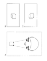
- FIG. 1 is a principle diagram of stereoscopic viewing using a parallax image.
- FIG. 1A is a top view of a user looking at a relatively small cube in front
- FIG. 1B is an appearance of the cube when the cube is viewed with the left eye.
- FIG. 1 (c) shows how the cube looks when the cube is viewed with the right eye.
- images of different angles are captured by the left and right eyes.
- Stereoscopic vision is realized by synthesizing images of different angles captured by the left and right eyes with the brain.
- the advantage of this method is that stereoscopic vision can be realized simply by preparing two viewpoint images for the right eye and left eye, so that the images corresponding to the left and right eyes can be displayed only to the corresponding eyes.
- a time-separation separation method In this method, a left-eye image and a right-eye image are alternately displayed on the display.
- the continuous stereo glasses With liquid crystal shutter
- the left-eye video and the right-eye video are superimposed and recognized as a stereoscopic video by the afterimage reaction of the eyes.
- the continuous stereo glasses put the liquid crystal shutter corresponding to the left eye in a transmissive state and the liquid crystal shutter corresponding to the right eye in a light shielding state. .
- the liquid crystal shutter corresponding to the right eye is set to the transparent state and the liquid crystal shutter corresponding to the left eye is set to the light-shielding state, contrary to the previous case.
- the video corresponding to the left and right eyes can be shown only to the corresponding eyes.
- the left and right images are alternately displayed in the time axis direction.
- 24 images are displayed per second. It is necessary to display 48 images per second by combining the left and right images. Therefore, this method is suitable for a display that can rewrite one screen relatively quickly.
- lenticular lenses In the time separation method, the left and right images are alternately displayed on the display in the time axis direction, whereas the left-eye picture and the right-eye picture are alternately arranged in the vertical direction in one screen at the same time. Affix the lenticular lens to the display surface.
- the pixels constituting the left-eye picture are focused only on the left eye
- the pixels constituting the right-eye picture are focused only on the right eye. Since the left and right eyes can show a picture with parallax, the user can recognize the video displayed on the display as a stereoscopic video.
- a vertically polarized filter is installed on the left-eye pixel
- a horizontally polarized filter is installed on the right-eye pixel
- the user is polarized glasses with a vertically polarized filter installed on the left-eye and a horizontally polarized filter on the right-eye.
- the displayed image can also be recognized as a stereoscopic image by looking at the display through the screen.
- the stereoscopic vision using the above-described parallax images is already used generally in amusement park playground equipment and the like, and since it is technically established, it can be said that it is the closest to practical use at home.
- various techniques such as a two-color separation method have been proposed as a method for stereoscopic viewing using a parallax image.
- FIG. 2 is a diagram showing the configuration of the BD-ROM.
- the BD-ROM is shown in the fourth level of the figure, and the tracks on the BD-ROM are shown in the third level.
- the track in this figure is drawn by extending the track formed in a spiral shape from the inner periphery to the outer periphery of the BD-ROM in the horizontal direction.
- This track includes a lead-in area, a volume area, and a lead-out area.
- the volume area in this figure has a layer model of a physical layer, a file system layer, and an application layer.
- the application layer format (application format) of the BD-ROM is expressed using the directory structure, it becomes like the first level in the figure.
- the BD-ROM has a BDMV directory immediately under the ROOT directory, and under the BDMV directory are an index file (index.bdmv), a PLAYLIST directory, a CLIPINFO directory, a STREAM directory, and a PROGRAM directory.
- index.bdmv an index table indicating the title structure is stored.
- the title is a unit of reproduction. For example, the main part of the movie is recorded as the first title, the director's cut is recorded as the second title, and bonus content is recorded as the third title.
- the user can specify a title to be played, such as “playback of title N”, using a remote control attached to the playback device.
- the STREAM directory stores a file (XXX.M2TS) storing AV clips in which AV contents such as video and audio are multiplexed.
- FIG. 3 is a diagram illustrating an example of a configuration of an AV clip stored in a file (XXX.M2TS).
- the file (XXX.M2TS) stores a digital stream in the MPEG-2 transport stream format in which a left-eye video stream and a right-eye video stream are multiplexed.
- the video stream for the left eye is a video stream that is played back as 2D video, and is played back as video for the left eye when the user performs stereoscopic viewing of a moving image (played back as 3D video).
- Video stream is a digital stream in the MPEG-2 transport stream format in which a left-eye video stream and a right-eye video stream are multiplexed.
- the video stream for the left eye is a video stream that is played back as 2D video, and is played back as video for the left
- the right-eye video stream is a video stream that is reproduced together with the left-eye video stream when the user performs stereoscopic viewing of a moving image. Further, as shown in FIG. 3, 0x1011 is assigned as the PID to the left-eye video stream, and 0x1012 different from the PID of the left-eye video stream is assigned to the right-eye video stream. As a result, each video stream can be identified.
- Each video stream is compressed and recorded by a method such as MPEG-2, MPEG-4 AVC, SMPTE VC-1, or the like.
- the audio stream is compressed and recorded by a method such as Dolby AC-3, Dolby Digital Plus, MLP, DTS, DTS-HD, and linear PCM.
- FIG. 4 is a diagram illustrating the relationship between the AV clip and the PL.
- the play list information is composed of one or more play item (PI) information, and each play item information indicates a playback section for an AV clip.
- PI play item
- Each piece of play item information is identified by a play item ID and is described in the order in which it should be reproduced in the playlist.
- the playlist information includes an entry mark indicating the playback start point.
- the entry mark can be given within the playback section defined by the play item information. As shown in FIG. 4, the entry mark is attached to a position that can be a playback start point for the play item information. Used. For example, chapter reproduction can be performed by adding an entry mark to the beginning of a chapter in a movie title.
- a reproduction path of a series of play item information is defined as a main path.
- FIG. 5 is a diagram showing an example of AV clip management information stored in the clip information file.
- AV clip management information has a one-to-one correspondence with AV clips, and includes clip information, stream attribute information, and an entry map.
- the entry map includes entry map header information, a PTS (Presentation Time-Stamp) indicating the start display time of each GOP (Group of Pictures) constituting the left-eye video stream, and the start position of the GOP in the AV clip.
- PTS Presentation Time-Stamp
- Table information indicating a pair with an SPN (Source Packet Number) and table information regarding a video stream (sub-picture) are described.
- SPN Source Packet Number
- entry point ID A value incremented for each entry point starting from 0 is referred to as an entry point ID (hereinafter also referred to as “EP_ID”).
- entry map header information information such as the PID of the left-eye video stream and the number of entry points is stored.
- the playback device converts the time information into address information when the playback start point is designated by time, and an AV clip corresponding to an arbitrary point on the time axis of the video stream.
- the upper packet position can be specified.
- BD program file (AAA.PROG) storing a program for defining a dynamic scenario is stored.
- BD-ROM In BD-ROM, a proprietary interpreter program called command navigation is used, but since the language system is not the essence of the present invention, it is written in a general-purpose programming language such as Java (registered trademark) or JavaScript. It can be a program. A play list to be reproduced is designated by this program. 3. PTS of video stream for left eye and video stream for right eye Next, the PTS of the left-eye video stream and the right-eye video stream for allowing the user to perform stereoscopic viewing of a moving image will be described.
- Java registered trademark
- JavaScript JavaScript
- FIG. 6 is a diagram illustrating a relationship between display times (PTS) assigned to a plurality of pictures constituting the left-eye video stream and display times (PTS) assigned to a plurality of pictures constituting the right-eye video stream.
- Each picture constituting the left-eye video stream has a one-to-one correspondence with the picture constituting the right-eye video stream (for example, the picture L1 and the picture R1 shown in FIG. 6 correspond), and the left-eye picture having a correspondence relationship
- the PTS is set so that the left-eye picture is displayed first in the right-eye picture.
- the PTS of the left-eye picture and the PTS of the right-eye picture are set so as to alternate on the time axis. This can be realized by setting the respective PTSs so that the display order of the left-eye picture and the right-eye video picture that are in the reference relationship of inter-picture prediction coding is alternated.
- the left-eye picture and the right-eye video picture that have a reference relationship for inter-picture prediction coding will be described.
- the video stream for the right eye is compressed by inter-picture predictive encoding using redundancy between viewpoints in addition to inter-picture predictive encoding using temporal redundancy. That is, the picture of the right-eye video stream is compressed with reference to the corresponding picture of the left-eye video stream.
- the video stream for the left eye and the video stream for the right eye have different viewpoints but the subject is the same, so the correlation between the images is large, and the amount of data of the video stream for the right eye is obtained by performing inter-picture predictive encoding between the viewpoints. This is because it can be significantly reduced compared to the data amount of the video stream for the left eye.
- FIG. 7 is a diagram illustrating a reference relationship between pictures.
- the P 0 picture of the right-eye video stream refers to the I 0 picture of the left-eye video stream
- the B 1 picture of the right-eye video stream refers to the Br 1 picture of the left-eye video stream
- the B 2 picture of the right-eye video stream refers to the Br 2 picture of the left-eye video stream
- the P 3 picture of the right-eye video stream refers to the P 3 picture of the left-eye video stream.
- the left-eye video stream does not refer to the right-eye video stream, the left-eye video stream can be played back alone, that is, can be played back as 2D video. Since it is referenced, it cannot be played back by the right-eye video stream alone.
- the time interval of the PTS between the left-eye picture and the right-eye picture corresponding to the left-eye picture will be described.
- the PTS of the corresponding right-eye picture for the left-eye picture displayed at a certain time needs to be set at an interval that satisfies the following expression. is there.
- PTS (for right eye) PTS (for left eye) + 1 / (number of frames per second ⁇ 2)
- the interval (display delay) between the left-eye picture and the right-eye picture corresponding to the left-eye picture is 1/48 seconds.
- each video stream is based on the PTS indicating the display time of each picture in each GOP and the DTS indicating the decoding time of each picture.
- multiplexing may be performed so that the left-eye picture and the right-eye picture corresponding to the left-eye picture are arranged in the vicinity.
- the left-eye picture and right-eye picture required at the required time can be obtained by sequentially reading from the beginning of the transport stream.
- the GOP time intervals of the left-eye video stream and the right-eye video stream are set to be equal, and each GOP of the left-eye video stream must have a one-to-one correspondence with the GOP of the right-eye video stream. is there. In this way, the left-eye video stream and the right-eye video stream can be synchronized in GOP units.
- the entry map is set for the left-eye video stream, so the time information (PTS) in the entry map is the playback start time of the first picture of each GOP of the left-eye video stream.
- the address information (SPN) indicates the address of the first packet of each GOP of the left-eye video stream in the AV clip. Since the playback device reads data from the position indicated by this address in the AV clip, the GOP of the right-eye video stream needs to be arranged behind the first packet constituting the GOP of the corresponding left-eye video stream.
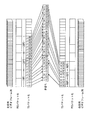
- FIG. 8 is a diagram schematically showing an example of multiplexing of the left-eye video stream and the right-eye video stream. As shown in FIG. 8, the left-eye video stream and the right-eye video stream are multiplexed in units of GOPs, and the GOP of the left-eye video stream precedes the GOP of the corresponding right-eye video stream.
- the time interval between the GOPs of the left-eye video stream and the right-eye video stream is made the same, and the GOP head of the left-eye video stream is always set to the GOP head of the corresponding right-eye video stream.
- FIG. 9 is a diagram schematically illustrating another example of multiplexing of the left-eye video stream and the right-eye video stream.
- 8 and 9 it is common that the GOP head of the left-eye video stream is always placed ahead of the GOP head of the corresponding right-eye video stream during multiplexing.
- the arrangement end position of the left-eye GOP and the right-eye GOP corresponding to the left-eye GOP is not limited, whereas in FIG. 9, the first packet of the left-eye GOP and the left-eye GOP The difference is that a right-eye GOP corresponding to the left-eye GOP is arranged between the GOP terminal packets.
- the AV clip can be cut without cutting the GOP of the right-eye video stream.
- FIG. 10 shows how each video stream is included in an AV clip when the right-eye GOP corresponding to the left-eye GOP is arranged between the left-eye GOP head packet and the left-eye GOP end packet. It is a figure which shows typically whether it is multiplexed.
- a left-eye video stream composed of a plurality of video frames is converted into a PES packet sequence and converted into a TS packet sequence.
- a right-eye video stream composed of a plurality of video frames is converted into a PES packet sequence and converted into a TS packet sequence.
- the leading packet (L11) of the leading GOP (LGOP1) of the left-eye video stream is arranged.
- Each packet (R11, R12, R13) of the GOP (RGOP1) of the right-eye video stream corresponding to LGOP1 is arranged after the packet (L11) arrangement position and ahead of the end packet (L16) of LGOP1.
- the first packet (L21) of the next GOP (LGOP2) of the left-eye video stream is arranged, and in the same way as before, the front packet (L26) of LGOP2 is forwarded to LGOP2.
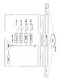
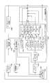
- FIG. 11 is a block diagram showing the configuration of the playback apparatus 2000. As shown in FIG.
- the playback device 2000 includes a BD-ROM drive 2100, a track buffer 2200, a system target decoder 2300, a plane adder 2400, a program memory 2500, a management information memory 2600, a program execution unit 2700, and a playback control unit 2800. , And a user event processing unit 2900.
- the BD-ROM drive 2100 reads data from the BD-ROM 1000 based on a read request input from the reproduction control unit 2800.
- the AV clip read from the BD-ROM 1000 is transferred to the track buffer 2200, the management information (index file, playlist file, and clip information file) is transferred to the management information memory 2600, and the BD program file is transferred to the program memory 2500.
- the management information index file, playlist file, and clip information file
- the track buffer 2200 is a buffer composed of a memory or the like for storing an AV clip input from the BD-ROM drive 2100.
- the system target decoder 2300 performs demultiplexing processing on the AV clip stored in the track buffer 2200, and performs stream decoding processing.
- Information such as the codec type and stream attribute necessary for decoding the stream included in the AV clip is transferred from the reproduction control unit 2800.
- the system target decoder 2300 includes a demultiplexer 2301, a video decoder 2302, a left-eye video plane 2303, a right-eye video plane 2304, a sub-video decoder 2305, a sub-video plane 2306, and a presentation graphics decoder (PG decoder) 2307.
- PG decoder presentation graphics decoder
- the demultiplexer 2301 extracts the TS packet stored in the track buffer 2200, and obtains a PES packet from the extracted TS packet. Based on the PID (packet identifier) included in the TS packet, the PES packet is output to any one of the video decoder 2302, the sub video decoder 2305, the PG decoder 2307, the IG decoder 2309, and the audio decoder 2313. Specifically, the PES packet obtained from the extracted TS packet is transmitted to the video decoder 2302 when the PID included in the TS packet is 0x1011 and 0x1012, and to the sub video decoder 2305 when the PID is 0x1B00.
- the data is transferred to the audio decoder 2313, when the PID is 0x1200 and 0x1201, to the PG decoder 2307, and when the PID is 0x1400, the data is transferred to the IG decoder 2309.
- the video decoder 2302 decodes the PES packet input from the demultiplexer 2301 to obtain an uncompressed picture, and writes it to either the left-eye video plane 2303 or the right-eye video plane 2304.
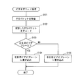
- FIG. 12 is a flowchart showing video decoding processing by the video decoder 2302.
- the video decoder 2302 decodes the received PES packet to obtain an uncompressed picture (step S102).
- step S103 It is determined whether the uncompressed picture constitutes the left-eye video frame or the right-eye video stream. This determination is made, for example, when the demultiplexer 2301 transmits the PES packet to the video decoder 2302, based on the PID included in the TS packet, the PES packet corresponds to the left-eye video stream or the right-eye video stream. This is done by adding a flag indicating whether or not the video decoder 2302 indicates that the flag corresponds to the left-eye video stream.
- step S104 If it is determined that the uncompressed picture constitutes the left-eye video frame (Yes in step S103), the picture is written in the left-eye video plane 2303 (step S104).
- step S105 If it is determined that the uncompressed picture constitutes the right-eye video frame (No in step S103), the picture is written in the right-eye video plane 2304 (step S105).
- the left-eye video plane 2303 is a plane for storing a left-eye uncompressed picture.
- a plane is a memory area for storing pixel data for one screen in the playback apparatus.
- the resolution in the video plane is 1920 ⁇ 1080, and the picture data stored in the video plane is composed of pixel data expressed by 16-bit YUV values.
- the right-eye video plane 2304 is a plane for storing uncompressed pictures for the right eye.
- the video decoder 2302 writes a picture at the PTS timing of the video frame.
- the sub video decoder 2305 has the same configuration as that of the video decoder 2302, decodes the video frame input from the demultiplexer 2301, and writes an uncompressed picture to the sub video plane 2306 at the display time (PTS) timing. .
- the sub video plane 2306 is a plane for storing a non-compressed picture of a sub video.
- the PG decoder 2307 decodes the presentation graphics stream input from the demultiplexer 2301, and writes uncompressed graphics data to the PG plane 2308 at the display time (PTS) timing.
- the PG plane 2308 is a plane for storing graphics data.
- the IG decoder 2309 decodes the interactive graphics stream input from the demultiplexer 2301, and writes uncompressed graphics data to the IG plane 2310 at the display time (PTS) timing.
- the IG plane 2310 is a plane for storing graphics data.
- the image processor 2311 decodes the graphics data (PNG / JPEG) input from the program execution unit 2700 and outputs it to the image plane 2312.
- the decoding timing of the image plane 2312 is instructed from the program execution unit 2700 when the graphics data is menu data, and from the playback control unit 2800 when the graphics data is subtitle data. .
- the image plane 2312 is a plane for storing graphics data (PNG / JPEG).
- the audio decoder 2313 decodes the PES packet input from the demultiplexer 2301 and outputs uncompressed audio data.
- the plane addition unit 2400 selects a plane in which a picture is written at the PTS timing from the left-eye video plane 2303 and the right-eye video plane 2304, and selects the selected plane, sub video plane 2306, PG plane 2308, and IG plane. 2310 and the image plane 2312 are instantaneously superimposed to generate a video signal and output it to a display such as a television.
- the video signal includes a flag indicating which one of the left-eye picture and the right-eye picture is superimposed.
- the program memory 2500 is a memory for storing a BD program file input from the BD-ROM drive 2100.
- the management information memory 2600 is a memory for storing an index table, management information, and playlist information input from the BD-ROM drive 2100.
- the program execution unit 2700 executes the program stored in the BD program file stored in the program memory 2500. Specifically, based on a user event input from the user event processing unit 2900, the playback control unit 2700 is instructed to play a playlist, or the system target decoder 2300 is used for menu or game graphics. Transfer PNG / JPEG.
- the playback control unit 2800 has a function of controlling the playback of AV clips by controlling the BD-ROM drive 2100 and the system target decoder 2300. For example, on the basis of a playback command input from the program execution unit 2700, the playback processing of the AV clip is controlled with reference to playlist information stored in the management information memory 2600. Further, at the time of random access, the head position of the GOP corresponding to the time information registered in the entry map stored in the management information memory 2600 is specified, and the BD-ROM drive 2100 is read out from that position. Instruct. Thereby, it is possible to perform processing efficiently without analyzing the AV clip. Furthermore, the playback control unit 2800 performs status acquisition and status setting in the playback device.
- the user event processing unit 2900 outputs a user event indicating the operation to the program execution unit 2700 in response to a key operation on the remote control or the front panel of the playback device.
- FIG. 13 is a diagram illustrating a home system including a BD-ROM 1000, a playback device 2000, a display 3000, stereoscopic glasses 4000, and a remote controller 5000.
- the playback device 2000 and the display are connected by, for example, an HDMI (High-Definition Multimedia Interface) cable.
- HDMI High-Definition Multimedia Interface
- Display 3000 displays video signals input from playback device 2000 in a time-sharing manner. Since the left-eye video and the right-eye video are alternately input from the playback device 2000, the display 3000 alternately displays the left-eye video and the right-eye video in the time axis direction.
- the difference from a display that displays 2D video is that the screen needs to be switched more quickly in order to display left-eye and right-eye video alternately. For example, many movies are shot at 24p (24 frames displayed per second), but in the case of 3D video, 24 frames for the left eye and 24 frames for the right eye are alternately displayed per second. Since it is necessary to display, it is necessary to rewrite 48 frames per second.
- the display 3000 sends a control signal indicating whether the video displayed on the display is for the left eye or the right eye to the stereoscopic glasses 4000 based on a flag included in the video signal input via the HDMI cable. Send.
- the stereoscopic glasses 4000 are special glasses using a liquid crystal shutter or the like, as described in the principle of stereoscopic vision in the first embodiment, used when viewing 3D video by the sequential separation method.
- the stereoscopic glasses 4000 switch between the liquid crystal shutter corresponding to the left eye and the liquid crystal shutter corresponding to the right eye in a transmissive state or a light shielding state based on a control signal transmitted from the display 3000. Specifically, when a control signal indicating that the left-eye video is being displayed is received from the display, the liquid crystal shutter corresponding to the left eye is set to the transmissive state, and the liquid crystal shutter corresponding to the right eye is set to the light-shielded state. . When the control signal indicating that the right-eye video is displayed is received, the liquid crystal shutter corresponding to the right eye is set in the transmission state, and the liquid crystal shutter corresponding to the left eye is set in the light shielding state.
- the recording area of the digital stream after the position indicated by the SPN corresponding to the PTS includes Since the GOP of the left-eye video stream and the GOP of the right-eye video stream corresponding to the GOP exist, it is possible to surely make the user stereoscopically view the moving image.
- Emodiment 2 In the present embodiment, a mode for carrying out a recording apparatus and a recording method according to the present invention will be described.
- the recording device is installed in a production studio for distribution of movie content, generates a digital stream compressed and encoded according to the MPEG standard, and a scenario describing how to play a movie title, and includes these data A volume image for BD-ROM is generated.
- the recording apparatus generates the recording medium described in the first embodiment.
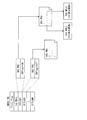
- FIG. 14 is a block diagram showing an internal configuration of the recording apparatus 40.
- the recording device 40 includes a video encoder 41, a material production unit 42, a scenario generation unit 43, a BD program production unit 44, a multiplexing processing unit 45, and a format processing unit 46.
- the video encoder 41 encodes an image image such as an uncompressed bitmap of the left-eye image and an image image such as an uncompressed bitmap of the right-eye image according to a compression method such as MPEG4-AVC or MPEG2, and the video for the left eye Create a stream and a right-eye video stream.
- a compression method such as MPEG4-AVC or MPEG2
- the video for the left eye Create a stream and a right-eye video stream.
- the GOP time intervals of the left-eye video stream and the right-eye video stream are set to be equal.
- FIG. 15 is a diagram illustrating how to efficiently generate a 3D video elementary stream.
- FIG. 15A is a diagram showing a left-eye picture at a certain time
- FIG. 15B is a diagram showing a left-eye picture at a time next to the video time shown in FIG. 15A.
- the video encoder 41 searches for a cube or a circle existing in the left-eye picture shown in FIG. 15A in the left-eye picture shown in FIG.
- each video frame sequence needs to be compressed separately. It takes twice as long to compress.
- FIG. 15C is a diagram showing a table that describes how much each search object has moved in which direction.
- the material production unit 42 creates each stream such as an audio stream, a presentation graphics stream, and an interactive graphics stream. More specifically, an audio stream is created by encoding uncompressed LinearPCM audio or the like according to a compression method such as AC3.
- a presentation graphics stream which is a subtitle stream format compliant with the BD-ROM standard, is created based on subtitle information files including subtitle images, display timing, and subtitle effects such as fade-in / fade-out.
- an interactive graphics stream that is a format of the menu screen compliant with the BD-ROM standard create.
- the scenario generation unit 43 generates a scenario in a format conforming to the BD-ROM standard in accordance with the information of each stream generated by the material production unit 42 and the user operation.
- the scenario mentioned here is a file such as an index file, a movie object file, and a playlist file.
- the scenario generation unit 43 creates a parameter file that describes which stream each AV clip is configured for realizing the multiplexing process.
- the created index file, movie object file, playlist file, and other files have the data structure described in the first embodiment.
- the BD program production unit 44 is a means for programming the program of the BD program file.
- a source code of a BD program file is created according to a request from the user through a user interface such as a GUI, and a BD program is created.
- the multiplexing processing unit 45 multiplexes a plurality of streams such as a left-eye video stream, a right-eye video stream, an audio stream, a presentation graphics stream, and an interactive graphics stream described in the BD-ROM scenario data, Create an AV clip in MPEG2-TS format.
- the left-eye video stream and the right-eye video stream are multiplexed in units of GOPs in such a form that the head of the GOP of the left-eye video stream precedes the GOP of the corresponding right-eye video stream.
- a clip information file paired with the AV clip is also created.
- Generation in the clip information file by the multiplexing processing unit 45 is performed by the following method.
- the multiplexing processing unit 45 generates an entry map in which the storage position of the first packet of each GOP of the left-eye video stream in the created AV clip is associated with the display time of the head of the GOP, and the generated entry A clip information file is created by pairing a map with attribute information indicating an audio attribute, a video attribute, and the like for each stream included in the AV clip.
- the clip information file has the data structure described in the first embodiment.
- the format processing unit 46 includes the BD-ROM scenario data generated by the scenario generating unit 43, the BD program file generated by the BD program generating unit 44, and the AV clip and clip information file generated by the multiplexing processing unit 45.
- a disk image is created in a UDF format, which is a file system compliant with the BD-ROM standard, arranged in a format compliant with the BD-ROM standard.
- a BD-ROM can be manufactured by converting the generated disk image into BD-ROM press data and performing a press process on the data. (Embodiment 3) In this embodiment, a case where 2D video and 3D video are mixed on a BD-ROM disc will be described.
- the user can select whether or not to wear the above-described stereoscopic viewing glasses according to each disc.
- the user needs to wear or unplug glasses at some timing.
- FIG. 16 is a diagram illustrating a configuration of an index table including a 3D correspondence flag. As shown in FIG. 16, a 3D correspondence flag indicating whether the video in the title is 2D or 3D is provided for each title. The title is switched by a user operation using a remote controller, a command, or the like.
- the playback device can notify the user of the timing of attaching / detaching the stereoscopic glasses to the user through OSD (On Screen Display), voice guidance, or the like. .
- OSD On Screen Display
- voice guidance or the like.
- the 3D correspondence flag indicating 2D video or 3D video is set for each title, but a 3D correspondence flag may be set for each playlist, play item, or AV stream.
- a 3D correspondence flag may be set for each playlist, play item, or AV stream.
- FIG. 17 is a diagram illustrating an example of a configuration of an AV clip stored in the STREAM directory.
- the AV clip for the left eye is the same as the AV clip shown in FIG. 3 except that it does not include the video stream for the right eye.
- the left-eye AV stream stores a left-eye video stream
- the left-eye video stream (main video) is 2D video in a playback device that plays back 2D video, and in a playback device that can play back 3D video, It is a video stream that is played back as a video for the left eye when playing back 3D video.
- the right-eye video stream is stored in the right-eye AV clip (sub-clip).
- the right-eye video stream is a video stream that is reproduced together with the left-eye video stream as a right-eye video when the 3D video is played back by a playback device capable of playing back the 3D video.
- the playlist information includes one or more sub play item (SubPI) information in addition to a main path that is a reproduction path of a series of play item information.
- a playback path of a series of sub play items that are played back in synchronization with the main path is defined as a sub path.
- Each sub play item information indicates a playback section for the sub clip.
- the reproduction section of each sub play item information is represented on the same time axis as the main path.
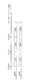
- FIG. 18 is a diagram showing the structure of a playlist when the left-eye video stream and the right-eye video stream are separate digital streams.
- the 2D playlist information is playlist information when the left-eye video stream is played back as 2D video
- the 3D playlist information is played when the left-eye video stream and the right-eye video stream are played back as 3D video.
- List information As shown in FIG. 18, the main path of the 2D playlist information and the 3D playlist information refers to an AV clip that stores the left-eye video stream.
- the 3D playlist information has a sub path in addition to the main path.
- the sub-path refers to a sub-clip that stores the right-eye video stream, and is set to synchronize with the main path on the time axis.
- the 2D playlist information and the 3D playlist information can share the AV clip in which the video stream for the left eye is stored.
- the 3D playlist information the left-eye video and the right-eye video are synchronized on the time axis. Can be made.
- each digital stream Since the left-eye video stream and the right-eye video stream are separate digital streams, a clip information file exists for each digital stream. Basically, both clip information files have the same configuration as the clip information file described in the first embodiment. Therefore, an entry map is set for the right-eye video stream.
- table information indicating a pair of entry map header information, a PTS indicating the start display time of each GOP constituting the right-eye video stream, and an SPN indicating the start position of the GOP in the sub clip. And are described.
- Each entry point in the table information has a PTS that is a value obtained by adding a display delay (1/48) seconds to the PTS specified in each entry point of the entry map of the left-eye video stream in the AV clip.
- the picture of the video stream for the right eye of the clip is registered. Thereby, when a certain time is designated, the playback apparatus can acquire the start address of the GOP in the right-eye video stream and the left-eye video stream corresponding to the time.
- the AV clip storing the left-eye video stream and the sub-clip storing the right-eye video stream are divided into extents (for example, in GOP units) and arranged in an interleaved manner.
- the GOP time intervals of the left-eye video stream and the right-eye video stream are the same.
- a preceding flag indicating which of the GOP of the left-eye video stream and the GOP of the right-eye video stream corresponding to the GOP is arranged first is set.
- the playback device indicates to the BD-ROM drive which of the GOP of the left-eye video stream and the GOP of the right-eye video stream corresponding to the GOP should be read by referring to the preceding flag. can do. That is, reading can be started from the GOP of the video stream indicated by the preceding flag.
- the 3D playlist information has one sub-path in addition to the main path.
- the 3D playlist information includes a plurality of sub-paths will be described.
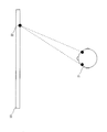
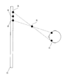
- FIG. 19 is a diagram illustrating the difference between the focal point of the eye when actually looking at the object and the focal point of the eye when performing stereoscopic viewing.
- FIG. 19B is a diagram illustrating a state where the user is actually looking at the object.
- the left eye 15 and the right eye 16 are both in focus at the position of the object 17. That is, for the user observing the object 17, this means that the position where the eyes are in focus and the position in the space where the object 17 is recognized are the same.
- FIG. 19A is a diagram illustrating a state in which the user performs stereoscopic viewing using a parallax image.
- the left eye 11 and the right eye 12 are focused on the display 14 while the stereoscopic viewing is performed.
- the image 13 is recognized in the brain so that it is imaged at the intersection of the straight lines connecting both eyes and the display. That is, while the binocular is focused on the display 14, the position where the 3D object 13 is recognized is a position protruding from the display 14.
- the difference between the focal position and the object recognition position is felt as a sense of discomfort or fatigue when 3D is recognized from the parallax image.
- One method for reducing the load on the user with 3D video using parallax images is to record a plurality of right-eye video streams with different projecting distances (angles at which the subject is viewed) as separate AV clips on a recording medium. Record it and let the user select it.
- AV clips for users who are accustomed to watching 3D video or who want to enjoy the presence of objects with more emphasis on popping out of objects, and for those who are not accustomed to watching 3D video suppress pop-up from the display.
- An AV clip that reduces a sense of discomfort during viewing may be prepared and the user may select it appropriately.
- FIG. 20 is a diagram showing playlist information when there are a plurality of sub-paths.
- the playlist information shown in FIG. 20 refers to the sub-clip 1 group and the sub-clip 2 group, both of which store the right-eye video stream, but differ in the viewing angle (jumping distance) of the subject.
- Each sub path and the main path are synchronized, and IDs are assigned to the sub paths in the order registered in the playlist information, and are used as sub path IDs to identify the sub paths.
- the subpath with the subpath ID “0” refers to the subclip 1 group
- the subpath with the subpath ID “1” refers to the subclip 2 group.
- the 3D playlist information includes a plurality of sub clips having different pop-up conditions, and the sub path to be reproduced is switched in synchronization with the main path for storing the left-eye video stream based on the size of the display screen or the user operation.
- Modification 3 In the second modification, the case where the 3D playlist information includes a plurality of sub paths has been described.
- audio data, subtitles, and menus are combined with each sub clip will be described.
- FIG. 21 is a diagram illustrating a state in which the user 21 is viewing the object 22 displayed on the display 23 in the reproduction of 2D video.
- the phase of the sound emitted from a plurality of speakers is used in order to make the user feel that the sound is emitted from the position of the object 22.
- FIG. 22 is a diagram showing a state in which an object appears to jump out from the display 33 to the user 31 side during playback of 3D video.
- the object In the left-eye video stream, the object is drawn at a position 34, and the right-eye video is displayed. By drawing the object at the position 35 in the stream, the user 31 recognizes that the object is at the position 36 in the space, and appears to jump out.
- the sound from the object is localized at the position 32 using the same sound as in the 2D video reproduction, the sound from the object is positioned even though the user 31 recognizes the object at the position 36. It sounds like it is from 32.
- audio data corresponding to each of a plurality of right-eye video streams at different angles for viewing the subject is stored in association with the right-eye video data so that the user can hear sound from the position where the object is recognized. deep.
- subtitles and menus are similarly stored in association with each right-eye video data.
- video data with different pop-ups was supported.
- Subtitles and menus can be displayed, and the presence can be increased.
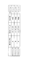
- FIG. 23 is a diagram showing a table in which audio data, subtitles, and menus are associated with each sub clip. As shown in FIG. 23, by holding a table in which audio data corresponding to each sub clip is described in a playlist, it is possible to switch corresponding audio data in accordance with switching of sub clips.
- the AV clip has an entry map related to the left-eye video stream, and each GOP of the left-eye video stream precedes the GOP of the right-eye video stream corresponding to the GOP.
- the AV clip has an entry map related to the right-eye video stream, and each GOP of the right-eye video stream is disposed at a position corresponding to the GOP and preceding the GOP of the left-eye video stream. It may be.
- the playback device includes the left-eye video plane and the right-eye video plane. However, the playback device may include only one video plane. In this case, the playback device writes left-eye pictures and right-eye pictures alternately on the video plane.
- the playback apparatus is configured to include one video decoder, but may include two video decoders, a left-eye video decoder and a right-eye video decoder.
- the demultiplexer outputs the PES packet to either the left-eye video decoder or the right-eye video decoder based on the PID included in the TS packet.
- the PTS of the corresponding right-eye picture is PTS (for left eye) + 1 / (number of frames per second ⁇ 2)
- the PTS of the right-eye picture may be between the corresponding left-eye picture and the next left-eye picture.
- the AV clip has an entry map related to the left-eye video stream.
- the AV clip may have an entry map of the left-eye video stream and the right-eye video stream.
- each entry point is a value obtained by adding a display delay (1/48) to the PTS specified by the entry point of the left-eye video stream in the AV clip entry map. PTS is set.
- the playback control unit 2800 starts playback from an address positioned ahead of the address information corresponding to the time in the left-eye entry map and right-eye entry map. As a result, the left-eye GOP and the right-eye GOP at the designated time can be read from the head.
- the left-eye video stream and the right-eye video stream are multiplexed without considering the storage position relationship. be able to.
- the right-eye GOP corresponding to the left-eye GOP is arranged between the head packet of the left-eye GOP and the end packet of the left-eye GOP.
- the right-eye GOP may be arranged between the first packet of the left-eye GOP and the first packet of the next left-eye GOP, or may be arranged by the end packet of the next left-eye GOP. .
- the display capable of displaying 3D video has been described. However, there are actually displays capable of displaying only 2D video. At that time, it is difficult for the user to determine whether or not the display supports 3D playback. Therefore, it is desirable for the playback device to determine whether or not the display supports 3D playback without the user being aware of it.
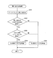
- FIG. 24 is a flowchart showing inquiry processing for inquiring of the display whether 3D display is possible. It is assumed that the playback device and the display are connected via an HDMI cable.
- the playback apparatus inquires of the display whether or not it is compatible with 3D (step S201). When a response indicating whether 3D is supported is received from the display (Yes in step S202), it is determined whether or not the response indicates that 3D is supported (step S203).
- step S203 If the response indicates that 3D is supported (Yes in step S203), the playback device displays a 3D display flag indicating that the display can be displayed in 3D within a predetermined memory in the device itself. Is set as valid (step S204), and the response indicates that 3D is not supported (No in step S203), or when there is no appropriate response from the display (No in step S202). The 3D display flag is set as invalid (step S205).
- the 3D display flag by making it possible to access the 3D display flag from the BD program, it becomes possible to determine whether the display connected to the playback apparatus supports 3D by the BD program. Thereby, for example, when the 3D display flag is valid, it is possible to control to play a 3D-compatible title, and when the 3D display flag is invalid, control to reproduce a 2D-compatible title.
- the playback device transmits 3D-compatible content to the display, information indicating that the content is 3D-compatible content may be included in the header or the like.
- specific processing such as not performing edge enhancement as described above on the display side is reduced or reduced, or appropriate processing is added to 3D viewing. Is possible.
- the sequential separation method and the polarized glasses method have been described as examples.
- a playlist for 3D playback may be played back by a BD-J application.
- BD-J application is a program execution part that fully implements Java2 Micro # Edition (J2ME) Personal Basis Profile (PBP 1.0) and Globally Excecutable MHP specification (GEM1.0.2) for package media targets. It is a Java application that is started as a life cycle.
- the program execution unit includes a Java (TM) (registered trademark) virtual machine, configuration, and profile.
- the BD-J application can start AV playback by instructing the Java TM virtual machine to generate a JMF player instance for playing back playlist information.
- a JMF (Java Media Frame work) player instance is actual data generated on a heap memory of a virtual machine based on a JMF player class.
- the program execution unit includes a standard Java library for displaying JFIF (JPEG), PNG, and other image data.
- JPEG JFIF
- PNG PNG
- other image data JPEG
- the BD-J application can implement a GUI framework.
- the GUI framework for Java applications includes the HAVi framework specified in GEM 1.0.2, and includes the remote control navigation mechanism in GEM 1.0.2.
- the BD-J application can realize screen display that combines button display, text display, and online display (BBS content) display based on the HAVi framework with the display of moving images. By using this, an operation for this screen display can be performed.
- BSS content online display
- the present invention can be widely applied to recording media for storing 3D video.
Landscapes
- Engineering & Computer Science (AREA)
- Signal Processing (AREA)
- Multimedia (AREA)
- Human Computer Interaction (AREA)
- Software Systems (AREA)
- Computer Graphics (AREA)
- Databases & Information Systems (AREA)
- Testing, Inspecting, Measuring Of Stereoscopic Televisions And Televisions (AREA)
- Signal Processing For Digital Recording And Reproducing (AREA)
- Television Signal Processing For Recording (AREA)
Priority Applications (11)
| Application Number | Priority Date | Filing Date | Title |
|---|---|---|---|
| RU2009134736/07A RU2505870C2 (ru) | 2008-01-17 | 2009-01-14 | Носитель записи, на который записано трехмерное видео, носитель записи для записи трехмерного видео и устройство воспроизведения и способ воспроизведения трехмерного видео |
| BRPI0902887A BRPI0902887A2 (pt) | 2008-01-17 | 2009-01-14 | meio de gravação no qual um vídeo 3d é gravado, meio de gravação para gravação de um vídeo 3d e dispoisitivo de reprodução e método para reprodução de um vídeo 3d |
| CA2680696A CA2680696C (en) | 2008-01-17 | 2009-01-14 | Recording medium on which 3d video is recorded, recording medium for recording 3d video, and reproducing device and method for reproducing 3d video |
| ES09702249.5T ES2659717T3 (es) | 2008-01-17 | 2009-01-14 | Medio de grabación en el que se graba vídeo en 3D, aparato de grabación para grabar vídeo en 3D y dispositivo de reproducción y método para reproducir vídeo en 3D |
| JP2009549981A JP4527808B2 (ja) | 2008-01-17 | 2009-01-14 | 3d映像が記録された記録媒体、3d映像を記録する記録装置、並びに3d映像を再生する再生装置及び再生方法 |
| AU2009205250A AU2009205250B2 (en) | 2008-01-17 | 2009-01-14 | Recording medium on which 3D video is recorded, recording medium for recording 3D video, and reproducing device and method for reproducing 3D video |
| DK09702249.5T DK2230844T3 (en) | 2008-01-17 | 2009-01-14 | REGISTRATION MEDIUM, WHICH 3D VIDEO IS REGISTERED, REGISTRATION MEDIUM FOR REGISTERING 3D VIDEO AND REPLACEMENT DEVICE AND METHOD OF REPRESENTING 3D VIDEO |
| MX2009009963A MX2009009963A (es) | 2008-01-17 | 2009-01-14 | Medio de grabacion en el cual se graba video en tercera dimension, medio de grabacion para grabar video en tercera dimension y dispositivo y metodo de reproduccion para reproducir video en tercera dimension. |
| EP09702249.5A EP2230844B1 (en) | 2008-01-17 | 2009-01-14 | Recording medium on which 3d video is recorded, recording apparatus for recording 3d video, and reproducing device and method for reproducing 3d video |
| CN2009800001745A CN101682719B (zh) | 2008-01-17 | 2009-01-14 | 3d影像的记录装置、方法以及3d影像的再现装置、方法 |
| ZA2009/05799A ZA200905799B (en) | 2008-01-17 | 2009-08-20 | Recording medium on which 3d video is recorded,recording medium for recording 3d video,and reproducing device and method for reproducing 3d video |
Applications Claiming Priority (2)
| Application Number | Priority Date | Filing Date | Title |
|---|---|---|---|
| US2181708P | 2008-01-17 | 2008-01-17 | |
| US61/021,817 | 2008-01-17 |
Publications (1)
| Publication Number | Publication Date |
|---|---|
| WO2009090868A1 true WO2009090868A1 (ja) | 2009-07-23 |
Family
ID=40885260
Family Applications (1)
| Application Number | Title | Priority Date | Filing Date |
|---|---|---|---|
| PCT/JP2009/000109 WO2009090868A1 (ja) | 2008-01-17 | 2009-01-14 | 3d映像が記録された記録媒体、3d映像を記録する記録装置、並びに3d映像を再生する再生装置及び再生方法 |
Country Status (15)
| Country | Link |
|---|---|
| US (2) | US8139930B2 (ru) |
| EP (1) | EP2230844B1 (ru) |
| JP (1) | JP4527808B2 (ru) |
| KR (1) | KR20100096000A (ru) |
| CN (1) | CN101682719B (ru) |
| AU (1) | AU2009205250B2 (ru) |
| BR (1) | BRPI0902887A2 (ru) |
| CA (1) | CA2680696C (ru) |
| DK (1) | DK2230844T3 (ru) |
| ES (1) | ES2659717T3 (ru) |
| MX (1) | MX2009009963A (ru) |
| MY (1) | MY148196A (ru) |
| RU (1) | RU2505870C2 (ru) |
| WO (1) | WO2009090868A1 (ru) |
| ZA (1) | ZA200905799B (ru) |
Cited By (25)
| Publication number | Priority date | Publication date | Assignee | Title |
|---|---|---|---|---|
| WO2010113730A1 (ja) * | 2009-04-03 | 2010-10-07 | ソニー株式会社 | 情報処理装置、情報処理方法、及び、プログラム |
| WO2010116998A1 (ja) * | 2009-04-08 | 2010-10-14 | ソニー株式会社 | 記録装置、記録方法、再生装置、再生方法、プログラム、および記録媒体 |
| JP2010259056A (ja) * | 2009-04-03 | 2010-11-11 | Sony Corp | 情報処理装置、情報処理方法、及び、プログラム |
| WO2010143439A1 (ja) * | 2009-06-12 | 2010-12-16 | パナソニック株式会社 | 再生装置、集積回路、記録媒体 |
| JP2011055148A (ja) * | 2009-08-31 | 2011-03-17 | Toshiba Corp | 映像合成装置、映像表示装置および映像合成方法 |
| WO2011064913A1 (ja) * | 2009-11-27 | 2011-06-03 | パナソニック株式会社 | 映像信号処理装置及び映像信号処理方法 |
| WO2011077673A1 (ja) * | 2009-12-21 | 2011-06-30 | パナソニック株式会社 | 再生装置 |
| CN102118592A (zh) * | 2009-12-31 | 2011-07-06 | 乐金显示有限公司 | 用于显示多视频的系统 |
| WO2011132404A1 (ja) * | 2010-04-20 | 2011-10-27 | パナソニック株式会社 | 3d映像記録装置及び3d映像信号処理装置 |
| JP2011529286A (ja) * | 2008-07-25 | 2011-12-01 | コーニンクレッカ フィリップス エレクトロニクス エヌ ヴィ | 字幕の三次元表示処理 |
| JP2012080267A (ja) * | 2010-09-30 | 2012-04-19 | Nec Personal Computers Ltd | 表示制御装置および表示制御方法 |
| JP2012100342A (ja) * | 2009-04-03 | 2012-05-24 | Sony Corp | 情報処理装置、情報処理方法、及び、プログラム |
| WO2012137829A1 (ja) * | 2011-04-04 | 2012-10-11 | 日立コンシューマエレクトロニクス株式会社 | 映像表示システム、表示装置、及び、表示方法 |
| US8593511B2 (en) | 2009-06-11 | 2013-11-26 | Panasonic Corporation | Playback device, integrated circuit, recording medium |
| JP2014197878A (ja) * | 2014-06-06 | 2014-10-16 | 日立マクセル株式会社 | 送受信システムおよび送受信方法 |
| JP2015092681A (ja) * | 2014-11-26 | 2015-05-14 | 日立マクセル株式会社 | 受信装置および受信方法 |
| JP2015149744A (ja) * | 2015-03-27 | 2015-08-20 | 日立マクセル株式会社 | 送受信システムおよび送受信方法 |
| JP2015149745A (ja) * | 2015-03-27 | 2015-08-20 | 日立マクセル株式会社 | 受信装置および受信方法 |
| JP2015159558A (ja) * | 2015-03-27 | 2015-09-03 | 日立マクセル株式会社 | 送受信システムおよび送受信方法 |
| JP2016134190A (ja) * | 2015-01-20 | 2016-07-25 | パナソニック インテレクチュアル プロパティ コーポレーション オブ アメリカPanasonic Intellectual Property Corporation of America | 再生制御方法、再生装置及び再生システム |
| WO2016116974A1 (ja) * | 2015-01-20 | 2016-07-28 | パナソニック インテレクチュアル プロパティ コーポレーション オブ アメリカ | 再生制御方法、再生装置及び再生システム |
| JP2016187202A (ja) * | 2016-06-09 | 2016-10-27 | 日立マクセル株式会社 | 受信装置および受信方法 |
| JP2016189609A (ja) * | 2016-06-09 | 2016-11-04 | 日立マクセル株式会社 | 送受信システムおよび送受信方法 |
| JP2017143551A (ja) * | 2017-03-22 | 2017-08-17 | 日立マクセル株式会社 | 受信装置および受信方法 |
| TWI626844B (zh) * | 2012-06-28 | 2018-06-11 | Ntt都科摩股份有限公司 | 動態影像預測解碼裝置、動態影像預測解碼方法 |
Families Citing this family (43)
| Publication number | Priority date | Publication date | Assignee | Title |
|---|---|---|---|---|
| US10742953B2 (en) * | 2009-01-20 | 2020-08-11 | Koninklijke Philips N.V. | Transferring of three-dimensional image data |
| US8451320B1 (en) * | 2009-01-23 | 2013-05-28 | Next3D, Inc. | Methods and apparatus for stereoscopic video compression, encoding, transmission, decoding and/or decompression |
| CN102396236B (zh) * | 2009-01-28 | 2015-03-25 | Lg电子株式会社 | 广播接收机及其视频数据处理方法 |
| JP5465523B2 (ja) * | 2009-01-29 | 2014-04-09 | 三洋電機株式会社 | 立体画像表示システム |
| US8369693B2 (en) * | 2009-03-27 | 2013-02-05 | Dell Products L.P. | Visual information storage methods and systems |
| JP4984183B2 (ja) * | 2009-04-07 | 2012-07-25 | ソニー株式会社 | 再生装置、再生方法、および記録方法 |
| JP5469911B2 (ja) * | 2009-04-22 | 2014-04-16 | ソニー株式会社 | 送信装置および立体画像データの送信方法 |
| JP5274359B2 (ja) * | 2009-04-27 | 2013-08-28 | 三菱電機株式会社 | 立体映像および音声記録方法、立体映像および音声再生方法、立体映像および音声記録装置、立体映像および音声再生装置、立体映像および音声記録媒体 |
| JP5400467B2 (ja) * | 2009-05-01 | 2014-01-29 | キヤノン株式会社 | 映像出力装置、その制御方法、及びプログラム |
| US20110013888A1 (en) * | 2009-06-18 | 2011-01-20 | Taiji Sasaki | Information recording medium and playback device for playing back 3d images |
| US8676041B2 (en) | 2009-07-04 | 2014-03-18 | Dolby Laboratories Licensing Corporation | Support of full resolution graphics, menus, and subtitles in frame compatible 3D delivery |
| JP5089658B2 (ja) * | 2009-07-16 | 2012-12-05 | 株式会社Gnzo | 送信装置及び送信方法 |
| US8289374B2 (en) | 2009-08-25 | 2012-10-16 | Disney Enterprises, Inc. | Method and system for encoding and transmitting high definition 3-D multimedia content |
| KR20110029319A (ko) * | 2009-09-15 | 2011-03-23 | 삼성전자주식회사 | 영상 처리 시스템 및 영상 처리 방법 |
| TWI404405B (zh) * | 2009-12-25 | 2013-08-01 | Mstar Semiconductor Inc | 具有螢幕顯示功能之影像處理裝置及影像處理方法 |
| JP2011139261A (ja) * | 2009-12-28 | 2011-07-14 | Sony Corp | 画像処理装置、画像処理方法、およびプログラム |
| US20110157302A1 (en) * | 2009-12-30 | 2011-06-30 | Ati Technologies Ulc | Three-dimensional video display system with multi-stream sending/receiving operation |
| JP2011146831A (ja) * | 2010-01-13 | 2011-07-28 | Sony Corp | 映像処理装置、映像制御方法及びコンピュータプログラム |
| KR20110088334A (ko) * | 2010-01-28 | 2011-08-03 | 삼성전자주식회사 | 3차원 멀티미디어 서비스를 제공하기 위한 데이터스트림 생성 방법 및 장치, 3차원 멀티미디어 서비스를 제공하기 위한 데이터스트림 수신 방법 및 장치 |
| US8712173B2 (en) * | 2010-03-12 | 2014-04-29 | Mediatek Singapore Pte. Ltd. | Methods for processing 2Nx2N block with N being positive integer greater than four under intra-prediction mode and related processing circuits thereof |
| WO2011121916A1 (ja) * | 2010-03-29 | 2011-10-06 | パナソニック株式会社 | 映像処理装置 |
| JP5577805B2 (ja) * | 2010-04-08 | 2014-08-27 | ソニー株式会社 | 情報処理装置、情報記録媒体、および情報処理方法、並びにプログラム |
| US9118896B2 (en) | 2010-04-21 | 2015-08-25 | Hitachi Maxell, Ltd. | Digital contents receiver, digital contents receiving method and digital contents transmitting and receiving method |
| JP5768332B2 (ja) * | 2010-06-24 | 2015-08-26 | ソニー株式会社 | 送信機、受信機及び通信システム |
| JP5537289B2 (ja) * | 2010-06-30 | 2014-07-02 | 日立コンシューマエレクトロニクス株式会社 | 記録装置/方法/媒体、再生装置/方法 |
| JP5637750B2 (ja) * | 2010-06-30 | 2014-12-10 | 日立コンシューマエレクトロニクス株式会社 | 記録装置/方法/媒体、再生装置/方法 |
| JP5537290B2 (ja) * | 2010-06-30 | 2014-07-02 | 日立コンシューマエレクトロニクス株式会社 | 記録装置/方法/媒体、再生装置/方法 |
| JP5527727B2 (ja) * | 2010-08-06 | 2014-06-25 | 日立コンシューマエレクトロニクス株式会社 | 映像表示システム及び表示装置 |
| US20120113218A1 (en) * | 2010-10-01 | 2012-05-10 | Manabu Sasamoto | Receiving apparatus and receiving method |
| EP2437513A1 (en) * | 2010-10-01 | 2012-04-04 | Hitachi Consumer Electronics Co. Ltd. | Receiver for 2D and 3D video content |
| US10424274B2 (en) | 2010-11-24 | 2019-09-24 | Ati Technologies Ulc | Method and apparatus for providing temporal image processing using multi-stream field information |
| US9485494B1 (en) | 2011-04-10 | 2016-11-01 | Nextvr Inc. | 3D video encoding and decoding methods and apparatus |
| US9407902B1 (en) | 2011-04-10 | 2016-08-02 | Nextvr Inc. | 3D video encoding and decoding methods and apparatus |
| US8681170B2 (en) | 2011-05-05 | 2014-03-25 | Ati Technologies Ulc | Apparatus and method for multi-streaming for more than three pixel component values |
| TWI501624B (zh) * | 2011-05-13 | 2015-09-21 | Innolux Corp | 保密顯示系統、保密顯示器、保密顯示方法及保密眼鏡 |
| TWI487381B (zh) * | 2011-05-19 | 2015-06-01 | Nat Univ Chung Cheng | Predictive Coding Method for Multimedia Image Texture |
| KR20140105367A (ko) * | 2011-12-28 | 2014-09-01 | 파나소닉 주식회사 | 재생장치, 송신장치, 재생방법 및 송신방법 |
| CN104221367A (zh) * | 2012-04-04 | 2014-12-17 | 拿索斯财务有限公司 | 用于生成和接收立体-2d反向兼容视频流的系统及其方法 |
| CN103428463B (zh) * | 2012-05-19 | 2016-10-12 | 腾讯科技(深圳)有限公司 | 3d视频源存储方法和装置及3d视频播放方法和装置 |
| US9860515B2 (en) * | 2012-12-11 | 2018-01-02 | Electronics And Telecommunications Research Institute | Apparatus and method for 3D content broadcasting with boundary information |
| JP2016506676A (ja) * | 2012-12-26 | 2016-03-03 | トムソン ライセンシングThomson Licensing | コンテンツプレゼンテーションのための方法および装置 |
| US20140212115A1 (en) * | 2013-01-31 | 2014-07-31 | Hewlett Packard Development Company, L.P. | Optical disc with three-dimensional viewing depth |
| WO2015006112A1 (en) | 2013-07-08 | 2015-01-15 | Dolby Laboratories Licensing Corporation | Processing of time-varying metadata for lossless resampling |
Citations (2)
| Publication number | Priority date | Publication date | Assignee | Title |
|---|---|---|---|---|
| WO1997032437A1 (en) * | 1996-02-28 | 1997-09-04 | Matsushita Electric Industrial Co., Ltd. | High-resolution optical disk for recording stereoscopic video, optical disk reproducing device, and optical disk recording device |
| JP2000270347A (ja) * | 1999-03-17 | 2000-09-29 | Sharp Corp | 記録装置、及び該記録装置を用いた監視システム |
Family Cites Families (13)
| Publication number | Priority date | Publication date | Assignee | Title |
|---|---|---|---|---|
| DE69614889T2 (de) * | 1995-09-29 | 2002-04-11 | Matsushita Electric Ind Co Ltd | Bitstromgenerierungsverfahren, optische Scheibe, Wiedergabe-Einrichtung und -Verfahren zur Aufnahme und Wiedergabe eines verschachtelten Bitstroms auf und von einer optischen Scheibe |
| US5886736A (en) * | 1996-10-24 | 1999-03-23 | General Instrument Corporation | Synchronization of a stereoscopic video sequence |
| RU2237283C2 (ru) * | 2001-11-27 | 2004-09-27 | Самсунг Электроникс Ко., Лтд. | Устройство и способ представления трехмерного объекта на основе изображений с глубиной |
| JP3948979B2 (ja) * | 2002-02-18 | 2007-07-25 | パイオニア株式会社 | 情報記録媒体、情報記録装置及び方法、情報再生装置及び方法、情報記録再生装置及び方法、記録又は再生制御用のコンピュータプログラム、並びに制御信号を含むデータ構造 |
| JP4251864B2 (ja) * | 2002-12-13 | 2009-04-08 | シャープ株式会社 | 画像データ作成装置およびそのデータを再生する画像データ再生装置 |
| JP4594766B2 (ja) * | 2004-03-10 | 2010-12-08 | パナソニック株式会社 | オーサリングシステム、プログラム、オーサリング方法。 |
| EP1746825B1 (en) * | 2004-04-16 | 2011-06-08 | Panasonic Corporation | Recording medium, reproduction device, program |
| JP4762145B2 (ja) * | 2004-09-03 | 2011-08-31 | パナソニック株式会社 | 記録媒体、記録装置、プログラム、記録方法、再生装置、再生方法 |
| JP4886689B2 (ja) * | 2005-07-15 | 2012-02-29 | パナソニック株式会社 | パケット送信装置 |
| KR20070022580A (ko) * | 2005-08-22 | 2007-02-27 | 엘지전자 주식회사 | 데이터 재생방법 및 재생장치, 기록매체와 데이터 기록방법및 기록장치 |
| JP4758997B2 (ja) * | 2005-10-27 | 2011-08-31 | パナソニック株式会社 | トランスポートストリーム生成装置およびこれを備えた記録装置、並びにトランスポートストリーム生成方法 |
| RU2473980C2 (ru) * | 2007-11-01 | 2013-01-27 | Панасоник Корпорэйшн | Носитель записи, устройство воспроизведения, устройство записи, способ воспроизведения и способ записи |
| EP2234109B8 (en) * | 2007-12-17 | 2016-06-01 | Panasonic Intellectual Property Corporation of America | Individual sales oriented recording medium, recording device, reproducing device and method for them |
-
2009
- 2009-01-14 MY MYPI20093863A patent/MY148196A/en unknown
- 2009-01-14 MX MX2009009963A patent/MX2009009963A/es active IP Right Grant
- 2009-01-14 EP EP09702249.5A patent/EP2230844B1/en active Active
- 2009-01-14 CN CN2009800001745A patent/CN101682719B/zh active Active
- 2009-01-14 CA CA2680696A patent/CA2680696C/en active Active
- 2009-01-14 BR BRPI0902887A patent/BRPI0902887A2/pt not_active Application Discontinuation
- 2009-01-14 RU RU2009134736/07A patent/RU2505870C2/ru not_active IP Right Cessation
- 2009-01-14 AU AU2009205250A patent/AU2009205250B2/en not_active Ceased
- 2009-01-14 WO PCT/JP2009/000109 patent/WO2009090868A1/ja active Application Filing
- 2009-01-14 DK DK09702249.5T patent/DK2230844T3/en active
- 2009-01-14 ES ES09702249.5T patent/ES2659717T3/es active Active
- 2009-01-14 KR KR1020097017473A patent/KR20100096000A/ko not_active Application Discontinuation
- 2009-01-14 JP JP2009549981A patent/JP4527808B2/ja active Active
- 2009-01-15 US US12/354,264 patent/US8139930B2/en active Active
- 2009-08-20 ZA ZA2009/05799A patent/ZA200905799B/en unknown
-
2012
- 2012-02-08 US US13/368,457 patent/US20120141097A1/en not_active Abandoned
Patent Citations (2)
| Publication number | Priority date | Publication date | Assignee | Title |
|---|---|---|---|---|
| WO1997032437A1 (en) * | 1996-02-28 | 1997-09-04 | Matsushita Electric Industrial Co., Ltd. | High-resolution optical disk for recording stereoscopic video, optical disk reproducing device, and optical disk recording device |
| JP2000270347A (ja) * | 1999-03-17 | 2000-09-29 | Sharp Corp | 記録装置、及び該記録装置を用いた監視システム |
Cited By (38)
| Publication number | Priority date | Publication date | Assignee | Title |
|---|---|---|---|---|
| US9979902B2 (en) | 2008-07-25 | 2018-05-22 | Koninklijke Philips N.V. | 3D display handling of subtitles including text based and graphics based components |
| JP2011529286A (ja) * | 2008-07-25 | 2011-12-01 | コーニンクレッカ フィリップス エレクトロニクス エヌ ヴィ | 字幕の三次元表示処理 |
| US8866885B2 (en) | 2009-04-03 | 2014-10-21 | Sony Corporation | Information processing device, information processing method, and program |
| JP2010259054A (ja) * | 2009-04-03 | 2010-11-11 | Sony Corp | 情報処理装置、情報処理方法、及び、プログラム |
| JP2012100342A (ja) * | 2009-04-03 | 2012-05-24 | Sony Corp | 情報処理装置、情報処理方法、及び、プログラム |
| US8971692B2 (en) | 2009-04-03 | 2015-03-03 | Sony Corporation | Information processing device, information processing method, and program |
| WO2010113730A1 (ja) * | 2009-04-03 | 2010-10-07 | ソニー株式会社 | 情報処理装置、情報処理方法、及び、プログラム |
| JP2010259056A (ja) * | 2009-04-03 | 2010-11-11 | Sony Corp | 情報処理装置、情報処理方法、及び、プログラム |
| US9756310B2 (en) | 2009-04-03 | 2017-09-05 | Sony Corporation | Information processing device, information processing method, and program |
| US8792780B2 (en) | 2009-04-08 | 2014-07-29 | Sony Corporation | Reproduction and recording apparatus and method for playing back and recording data encoded according to a predetermined standard |
| WO2010116998A1 (ja) * | 2009-04-08 | 2010-10-14 | ソニー株式会社 | 記録装置、記録方法、再生装置、再生方法、プログラム、および記録媒体 |
| US8593511B2 (en) | 2009-06-11 | 2013-11-26 | Panasonic Corporation | Playback device, integrated circuit, recording medium |
| WO2010143439A1 (ja) * | 2009-06-12 | 2010-12-16 | パナソニック株式会社 | 再生装置、集積回路、記録媒体 |
| US8121461B2 (en) | 2009-06-12 | 2012-02-21 | Panasonic Corporation | Playback device, integrated circuit, recording medium |
| JP2011055148A (ja) * | 2009-08-31 | 2011-03-17 | Toshiba Corp | 映像合成装置、映像表示装置および映像合成方法 |
| CN102668577A (zh) * | 2009-11-27 | 2012-09-12 | 松下电器产业株式会社 | 影像信号处理装置以及影像信号处理方法 |
| US8994787B2 (en) | 2009-11-27 | 2015-03-31 | Panasonic Intellectual Property Management Co., Ltd. | Video signal processing device and video signal processing method |
| JP2011114606A (ja) * | 2009-11-27 | 2011-06-09 | Panasonic Corp | 映像信号処理装置及び映像信号処理方法 |
| WO2011064913A1 (ja) * | 2009-11-27 | 2011-06-03 | パナソニック株式会社 | 映像信号処理装置及び映像信号処理方法 |
| WO2011077673A1 (ja) * | 2009-12-21 | 2011-06-30 | パナソニック株式会社 | 再生装置 |
| CN102118592A (zh) * | 2009-12-31 | 2011-07-06 | 乐金显示有限公司 | 用于显示多视频的系统 |
| CN102118592B (zh) * | 2009-12-31 | 2013-08-07 | 乐金显示有限公司 | 用于显示多视频的系统 |
| JP5374641B2 (ja) * | 2010-04-20 | 2013-12-25 | パナソニック株式会社 | 3d映像記録装置及び3d映像信号処理装置 |
| WO2011132404A1 (ja) * | 2010-04-20 | 2011-10-27 | パナソニック株式会社 | 3d映像記録装置及び3d映像信号処理装置 |
| JP2012080267A (ja) * | 2010-09-30 | 2012-04-19 | Nec Personal Computers Ltd | 表示制御装置および表示制御方法 |
| US9225963B2 (en) | 2011-04-04 | 2015-12-29 | Hitachi Maxell, Ltd. | Video display system, display apparatus, and display method |
| WO2012137829A1 (ja) * | 2011-04-04 | 2012-10-11 | 日立コンシューマエレクトロニクス株式会社 | 映像表示システム、表示装置、及び、表示方法 |
| TWI626844B (zh) * | 2012-06-28 | 2018-06-11 | Ntt都科摩股份有限公司 | 動態影像預測解碼裝置、動態影像預測解碼方法 |
| JP2014197878A (ja) * | 2014-06-06 | 2014-10-16 | 日立マクセル株式会社 | 送受信システムおよび送受信方法 |
| JP2015092681A (ja) * | 2014-11-26 | 2015-05-14 | 日立マクセル株式会社 | 受信装置および受信方法 |
| JP2016134190A (ja) * | 2015-01-20 | 2016-07-25 | パナソニック インテレクチュアル プロパティ コーポレーション オブ アメリカPanasonic Intellectual Property Corporation of America | 再生制御方法、再生装置及び再生システム |
| WO2016116974A1 (ja) * | 2015-01-20 | 2016-07-28 | パナソニック インテレクチュアル プロパティ コーポレーション オブ アメリカ | 再生制御方法、再生装置及び再生システム |
| JP2015159558A (ja) * | 2015-03-27 | 2015-09-03 | 日立マクセル株式会社 | 送受信システムおよび送受信方法 |
| JP2015149745A (ja) * | 2015-03-27 | 2015-08-20 | 日立マクセル株式会社 | 受信装置および受信方法 |
| JP2015149744A (ja) * | 2015-03-27 | 2015-08-20 | 日立マクセル株式会社 | 送受信システムおよび送受信方法 |
| JP2016187202A (ja) * | 2016-06-09 | 2016-10-27 | 日立マクセル株式会社 | 受信装置および受信方法 |
| JP2016189609A (ja) * | 2016-06-09 | 2016-11-04 | 日立マクセル株式会社 | 送受信システムおよび送受信方法 |
| JP2017143551A (ja) * | 2017-03-22 | 2017-08-17 | 日立マクセル株式会社 | 受信装置および受信方法 |
Also Published As
| Publication number | Publication date |
|---|---|
| US20120141097A1 (en) | 2012-06-07 |
| EP2230844A1 (en) | 2010-09-22 |
| CA2680696A1 (en) | 2009-07-23 |
| CN101682719A (zh) | 2010-03-24 |
| BRPI0902887A2 (pt) | 2015-09-22 |
| RU2009134736A (ru) | 2011-03-27 |
| KR20100096000A (ko) | 2010-09-01 |
| AU2009205250A2 (en) | 2009-12-10 |
| MX2009009963A (es) | 2009-10-08 |
| AU2009205250B2 (en) | 2013-02-21 |
| EP2230844B1 (en) | 2017-11-22 |
| JPWO2009090868A1 (ja) | 2011-05-26 |
| MY148196A (en) | 2013-03-15 |
| US8139930B2 (en) | 2012-03-20 |
| CN101682719B (zh) | 2013-01-30 |
| DK2230844T3 (en) | 2018-01-02 |
| RU2505870C2 (ru) | 2014-01-27 |
| AU2009205250A1 (en) | 2009-07-23 |
| CA2680696C (en) | 2016-04-05 |
| JP4527808B2 (ja) | 2010-08-18 |
| ZA200905799B (en) | 2011-10-26 |
| ES2659717T3 (es) | 2018-03-19 |
| EP2230844A4 (en) | 2014-07-30 |
| US20090220213A1 (en) | 2009-09-03 |
Similar Documents
| Publication | Publication Date | Title |
|---|---|---|
| JP4527808B2 (ja) | 3d映像が記録された記録媒体、3d映像を記録する記録装置、並びに3d映像を再生する再生装置及び再生方法 | |
| US8565576B2 (en) | Optical disc for reproducing stereoscopic video image | |
| JP5480915B2 (ja) | 表示装置と方法、記録媒体、送信装置と方法、及び再生装置と方法 | |
| US8503869B2 (en) | Stereoscopic video playback device and stereoscopic video display device | |
| JP5457465B2 (ja) | 表示装置と方法、送信装置と方法、及び受信装置と方法 | |
| JP4993224B2 (ja) | 再生装置および再生方法 | |
| JP5829604B2 (ja) | 3dトリックプレイのためのエントリー・ポイント | |
| JP2010283856A (ja) | 記録媒体、再生装置、及び集積回路 | |
| TW201123847A (en) | Recording medium, playback device, and integrated circuit | |
| WO2010116895A1 (ja) | 記録装置、記録方法、再生装置、再生方法、記録媒体、およびプログラム | |
| JP4984184B2 (ja) | 再生装置および再生方法 | |
| JP4984194B2 (ja) | 記録方法 | |
| JP4993233B2 (ja) | 記録方法 | |
| JP2012100335A (ja) | 再生装置、再生方法、および記録方法 | |
| JP2012135001A (ja) | 記録方法 | |
| JP2012120233A (ja) | 再生装置、再生方法、および記録方法 |
Legal Events
| Date | Code | Title | Description |
|---|---|---|---|
| WWE | Wipo information: entry into national phase |
Ref document number: 200980000174.5 Country of ref document: CN |
|
| REEP | Request for entry into the european phase |
Ref document number: 2009702249 Country of ref document: EP |
|
| WWE | Wipo information: entry into national phase |
Ref document number: 2009702249 Country of ref document: EP |
|
| WWE | Wipo information: entry into national phase |
Ref document number: 1020097017473 Country of ref document: KR |
|
| WWE | Wipo information: entry into national phase |
Ref document number: 2009205250 Country of ref document: AU |
|
| ENP | Entry into the national phase |
Ref document number: 2680696 Country of ref document: CA |
|
| ENP | Entry into the national phase |
Ref document number: 2009549981 Country of ref document: JP Kind code of ref document: A |
|
| 121 | Ep: the epo has been informed by wipo that ep was designated in this application |
Ref document number: 09702249 Country of ref document: EP Kind code of ref document: A1 |
|
| WWE | Wipo information: entry into national phase |
Ref document number: 2009134736 Country of ref document: RU Ref document number: PI20093863 Country of ref document: MY |
|
| WWE | Wipo information: entry into national phase |
Ref document number: 12009501777 Country of ref document: PH Ref document number: MX/A/2009/009963 Country of ref document: MX |
|
| ENP | Entry into the national phase |
Ref document number: 2009205250 Country of ref document: AU Date of ref document: 20090114 Kind code of ref document: A |
|
| NENP | Non-entry into the national phase |
Ref country code: DE |
|
| ENP | Entry into the national phase |
Ref document number: PI0902887 Country of ref document: BR Kind code of ref document: A2 Effective date: 20090916 |