WO2009090686A1 - 画像計測装置及びプログラム - Google Patents
画像計測装置及びプログラム Download PDFInfo
- Publication number
- WO2009090686A1 WO2009090686A1 PCT/JP2008/000036 JP2008000036W WO2009090686A1 WO 2009090686 A1 WO2009090686 A1 WO 2009090686A1 JP 2008000036 W JP2008000036 W JP 2008000036W WO 2009090686 A1 WO2009090686 A1 WO 2009090686A1
- Authority
- WO
- WIPO (PCT)
- Prior art keywords
- caliper
- reference point
- input
- rotation
- image
- Prior art date
- Legal status (The legal status is an assumption and is not a legal conclusion. Google has not performed a legal analysis and makes no representation as to the accuracy of the status listed.)
- Ceased
Links
Images







Classifications
-
- A—HUMAN NECESSITIES
- A61—MEDICAL OR VETERINARY SCIENCE; HYGIENE
- A61B—DIAGNOSIS; SURGERY; IDENTIFICATION
- A61B5/00—Measuring for diagnostic purposes; Identification of persons
- A61B5/103—Measuring devices for testing the shape, pattern, colour, size or movement of the body or parts thereof, for diagnostic purposes
- A61B5/107—Measuring physical dimensions, e.g. size of the entire body or parts thereof
- A61B5/1075—Measuring physical dimensions, e.g. size of the entire body or parts thereof for measuring dimensions by non-invasive methods, e.g. for determining thickness of tissue layer
-
- A—HUMAN NECESSITIES
- A61—MEDICAL OR VETERINARY SCIENCE; HYGIENE
- A61B—DIAGNOSIS; SURGERY; IDENTIFICATION
- A61B8/00—Diagnosis using ultrasonic, sonic or infrasonic waves
- A61B8/08—Clinical applications
Definitions
- the present invention relates to an image measuring apparatus and a program for displaying a medical image and measuring an angle of a characteristic part in the image.
- the ultrasonic diagnostic device transmits ultrasonic waves from a probe that is in contact with the body surface of the subject, receives ultrasonic signals (echo signals) reflected by each tissue in the body, and images based on the signals. It is a device that generates data, and is used for various diagnoses because of its high safety.
- the ultrasonic image created from the echo signal is displayed on a monitor provided in the ultrasonic diagnostic apparatus and used for various diagnoses. At this time, the length and area of the characteristic part depicted in the image Alternatively, there are cases where an angle or the like is measured and used for diagnosis, and various measurement programs have been developed (Patent Document 1). For example, in the diagnosis of congenital hip dislocation in an infant, a program for measuring the angle formed by the hip and femur in the rendered ultrasonic image is used.
- the user can automatically set the angle formed by arranging two linear calipers at arbitrary positions on the ultrasonic image using the program. It is measured.
- a conventional processing procedure for setting the linear caliper on the ultrasonic image will be described with reference to the flowchart of FIG.
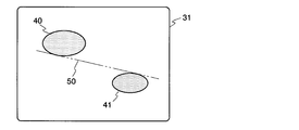
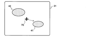
- FIG. 9 two feature parts 40 and 41 are depicted in the image, and the caliper for angle measurement is made to coincide with the target position 50 in the figure so as to be in contact with both. think of.
- the alternate long and two short dashes line indicates the target position 50, and the arrow indicates the reference point or caliper movement direction or rotation direction, which will be described later, for convenience and may not be displayed on the actual screen. Absent.
- the user instructs the start of setting of the caliper for angle measurement by performing a predetermined operation on the console of the ultrasonic diagnostic apparatus.
- a cross-shaped cursor representing the reference point 70 of the caliper is superimposed and displayed on the ultrasonic image displayed on the screen 31 of the monitor (step S21), and the reference point 70 is moved.
- Acceptance of quantity input is started.
- the user operates the trackball or the like on the console to input the movement amount of the reference point 70
- the reference point 70 moves up, down, left and right on the screen 31 accordingly (step S22), and the user performs a predetermined operation on the console.
- a key operation or the like is performed to instruct the determination of the reference point position, the position of the reference point 70 is determined at that time, and the input of the movement amount ends (steps S23 and S24).
- a linear caliper 71 extending from the reference point 70 in a predetermined direction is displayed on the screen 31 (step S25), and the caliper 71 rotates. Acceptance of quantity input is started.
- the user operates a trackball or the like on the console to input the rotation amount of the caliper 71
- the caliper 71 on the screen 31 rotates in response to the reference point 70 (step S26), and the user performs a predetermined operation on the console.
- the confirmation of the caliper 71 is instructed by performing the above key operation or the like, the inclination of the caliper 71 is confirmed at that time (FIG. 12), and the input of the rotation amount is finished (steps S27 and S28).
- the position of the reference point determined first is important.
- the reference point 70 is not set to an appropriate position in step S22.
- the caliper 71 is rotated in step S26, the caliper 71 cannot be matched with the target position 50.
- the present invention has been made to solve the above-described problems, and an object of the present invention is to provide an image measurement device and an angle measurement program capable of easily and appropriately setting the position and angle of an angle measurement caliper. It is to provide.
- An image measuring apparatus which is made to solve the above problems, displays a medical image and draws a linear caliper on the image, and measures an angle formed by the two calipers.
- caliper superimposing means for superimposing and displaying a linear caliper and a reference point indicating the rotation center of the caliper on the medical image;
- a movement instruction means for the user to input the movement amount of the caliper and the reference point;
- rotation instruction means for the user to input the amount of rotation of the caliper;
- Confirmation instruction means for the user to instruct confirmation of the position and inclination of the caliper;
- caliper control means for controlling the caliper superimposing means based on the input from each instruction means;
- the caliper control means translates the caliper and the reference point on the medical image according to the input from the movement instruction means, and moves the caliper on the medical image according to the input from the rotation instruction means.
- the rotation is performed while maintaining the position of the reference point, and
- movement amount means the direction and size of movement
- rotation amount means the direction and size of rotation
- the image measuring apparatus further includes start instruction means for a user to instruct start of setting of the caliper, and the caliper control means is configured to perform the medical use according to an input from the start instruction means. It is desirable to display the caliper and the reference point on the image and to start accepting inputs from the movement instruction unit and the rotation instruction unit.
- the image measurement apparatus can be, for example, an ultrasonic diagnostic apparatus.
- a separate input device provided on the console of the ultrasonic diagnostic apparatus is used as the movement instruction means or the rotation instruction means, respectively.
- a pointing device such as a trackball provided on the console as the movement instruction means
- a rotary encoder provided on the console as the rotation instruction means.
- a program according to the present invention made to solve the above problems is a program for drawing a linear caliper on a medical image and measuring an angle formed by the two calipers. a) superimposing and displaying a linear caliper and a reference point indicating the rotation center of the caliper on a medical image in response to an instruction to start caliper setting; b) Accepting an input of the amount of movement of the caliper and the reference point and an input of the amount of rotation of the caliper, moving the caliper and the reference point on the medical image in parallel according to the amount of movement, and according to the amount of rotation Rotating the caliper on the medical image while maintaining the position of the reference point; c) ending acceptance of the movement amount and the rotation amount in response to a caliper position and inclination determination instruction; It is characterized by having a computer execute.
- the position of the caliper and the reference point and the inclination of the caliper can be changed at the same time, so that the caliper can easily match the target position on the image.
- the angle of the characteristic part in the image can be measured accurately and efficiently.
- the block diagram which shows the principal part structure of the ultrasonic diagnosing device which concerns on one Example of this invention.
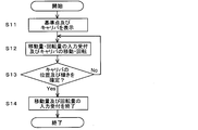
- the flowchart which shows the caliper setting process sequence in the ultrasonic diagnosing device of the Example.
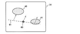
- the figure which shows the state which displayed the reference point and the caliper on the ultrasonic image in the ultrasonic diagnostic apparatus of the Example.
- the figure explaining the movement of the reference point and caliper in the ultrasonic diagnostic apparatus of the embodiment.
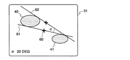
- the figure explaining rotation of a caliper in the ultrasonic diagnostic apparatus of the Example The figure which shows the state which determined the position and inclination of a caliper in the ultrasonic diagnosing device of the Example.
- the flowchart which shows the caliper setting process sequence in the conventional ultrasonic diagnostic apparatus.
- the figure which shows the target position of the characteristic site
- FIG. 1 is a block diagram showing a schematic configuration of an ultrasonic diagnostic apparatus according to an embodiment of the present invention.
- the ultrasonic probe 10 is pressed against the body of a subject (not shown), and transmits ultrasonic waves into the body of the subject under the control of the transmission / reception control unit 11 and reflects reflected waves from the body. Receive a wave.
- the received signal is input to the image signal processing unit 12, and an ultrasonic image is formed by performing predetermined arithmetic processing.
- the acquired ultrasonic image data is converted into a format that can be displayed on the screen 31 of the monitor 30 by the digital scan converter (DSC) 13, and is output to the monitor 30 via the display processing unit 14.
- DSC digital scan converter
- the graphic unit 16 generates a graphic including characters such as diagnostic information and a graphic such as a cursor for measurement or a caliper, and the graphic is synthesized with the ultrasonic image in the display processing unit 14. Thereby, on the screen 31 of the monitor 30, a character, a figure, etc. can be displayed on a superimposition with an ultrasonic image.
- the angle measurement unit 17 measures an angle formed by two angle measurement calipers drawn on an ultrasonic image, and character information representing a measurement result by the graphic unit 16 based on the obtained measurement value. It is generated and output to the display processing unit 14.
- each unit is controlled by a central control unit 15 including a CPU and the like, and an operation signal is input to the central control unit 15 from an operation console 20 including a keyboard 23, a trackball 21, a rotary encoder 22, and the like.
- the functions of each unit centering on the central control unit 15 are realized as software by causing the CPU to execute a predetermined program except for the input / output devices such as the ultrasonic probe 10, the control console 20, and the monitor 30. Alternatively, it may be configured by hardware using a circuit or the like. Moreover, the structure with which both were combined may be sufficient.
- the keyboard 23 corresponds to the start instruction means and the confirmation instruction means in the present invention
- the trackball 21 and the rotary encoder 22 correspond to the movement instruction means and the rotation instruction means in the present invention, respectively.
- the graphic unit 16 and the display processing unit 14 of this embodiment correspond to caliper superimposing means in the present invention
- the central control unit 15 corresponds to caliper control means in the present invention.
- the ultrasonic diagnostic apparatus of the present embodiment has a function of measuring an angle of an arbitrary location in an ultrasonic image by measuring an angle formed by two linear calipers displayed on the screen, The processing operation for setting the position and angle of the caliper is characteristic. Next, this point will be described in detail.
- FIG. 9 is a flowchart showing a processing procedure when the angle measurement caliper is set in the ultrasonic diagnostic apparatus of the present embodiment
- FIGS. 3 to 7 are views showing examples of screen display at that time.
- step S11 First, in a state where an ultrasonic image is displayed as a still image on the screen 31 of the monitor 30, the user performs a predetermined operation with the keyboard 23 to instruct display of the angle measurement caliper. As a result, the graphic unit 16 generates a graphic of the caliper for angle measurement and the reference point which is the rotation center thereof, and the graphic is synthesized with the ultrasonic image in the display processing unit 14. As a result, as shown in FIG. 3, a cross-shaped cursor representing the reference point 60 and a linear caliper 61 are superimposed on the screen 31 of the monitor 30.
- step S12 (2) Acceptance of input of movement amount and rotation amount and movement and rotation of caliper (step S12)
- the caliper 61 and the reference point 60 are in an undetermined state during the setting, and can be arbitrarily rotated or translated on the ultrasonic image in accordance with a user instruction.
- an input signal corresponding to the movement of the trackball 21 is received by the central control unit 15 as a movement amount of the reference point 60, and the reference point 60 and the caliper 61 are corresponding to the movement amount. Move in parallel on the screen 31 while maintaining the positional relationship between them and the inclination of the caliper (FIG. 4).
- step S13 Caliper determination (step S13), end of input of movement amount and rotation amount (step S14)
- the user operates the trackball 21 and the rotary encoder 22 while referring to the monitor 30 to adjust the position and inclination of the caliper 61, and performs a predetermined operation with the keyboard 23 when the caliper 61 matches the target position 50. To determine the position and inclination of the caliper 61.
- the reception of the movement amount from the trackball 21 and the reception of the rotation amount from the rotary encoder 22 in the central control unit 15 ends, and unless the user performs some operation again to restart these receptions.
- the caliper 61 is displayed as a broken line in an unconfirmed state, that is, in a state where it can be moved and rotated (FIGS. 3 to 5), and is displayed as a solid line after confirmation (FIGS. 6 and 7).
- the conventional ultrasonic diagnostic apparatus accepts the input of the caliper rotation amount after the reference point position is determined, the caliper can be rotated even if the caliper is rotated because the position of the reference point determined first is inappropriate. If the target position cannot be matched, it is necessary to once complete the adjustment of the caliper angle by a predetermined operation and restart the reception of the reference point movement amount to reset the reference point position.
- the input of the movement amount of the reference point (and the caliper) and the reception of the input of the caliper rotation amount are started at the same time.
- the position of the reference point 60 can be adjusted immediately by operating the trackball 21.
- the angle measuring caliper can be easily matched with the target position, and the angle of the characteristic part in the ultrasonic image can be accurately and efficiently measured. Will be able to.
- the two calipers 61 As described above, after the position and inclination of the caliper 61 on the ultrasonic image are confirmed, when the second caliper 62 is drawn on the ultrasonic image by the same procedure as described above, the two calipers 61, The angle ⁇ formed by 62 is automatically measured, and a character string representing the measured value of the angle ⁇ is displayed on the screen 31 as shown in FIG. Note that it is possible to draw three or more calipers on the screen 31. In that case, the user may specify two calipers to be used for angle measurement from among three or more calipers, the last two calipers drawn, or the first and last drawn calipers. The caliper may be automatically selected as a measurement target.
- each of the instruction means according to the present invention is not limited to that shown in the above embodiment, and for example, another pointing device may be used instead of the trackball.
- these instruction means can be software buttons, dials, etc. implemented in software. In this case, the user operates buttons and the like displayed on the monitor screen using various input devices provided on the console.
- the present invention is not limited to an X-ray CT image or MR image. The same can be applied to the case of reading and measuring in the same manner.
Landscapes
- Health & Medical Sciences (AREA)
- Life Sciences & Earth Sciences (AREA)
- Medical Informatics (AREA)
- Molecular Biology (AREA)
- Veterinary Medicine (AREA)
- Biophysics (AREA)
- Pathology (AREA)
- Engineering & Computer Science (AREA)
- Biomedical Technology (AREA)
- Heart & Thoracic Surgery (AREA)
- Public Health (AREA)
- Physics & Mathematics (AREA)
- Surgery (AREA)
- Animal Behavior & Ethology (AREA)
- General Health & Medical Sciences (AREA)
- Dentistry (AREA)
- Oral & Maxillofacial Surgery (AREA)
- Nuclear Medicine, Radiotherapy & Molecular Imaging (AREA)
- Radiology & Medical Imaging (AREA)
- Ultra Sonic Daignosis Equipment (AREA)
Abstract
医用画像上に直線状のキャリパを描出し、2本のキャリパが成す角度を計測する画像計測装置において、各キャリパの位置及び傾きを設定する際に、ユーザからのキャリパ設定開始の指示に応じて、医用画像上に直線状のキャリパ61及びその回転中心を示す基準点60を重畳表示し、ユーザからの基準点60及びキャリパ61の移動量の入力並びにキャリパ61の回転量の入力を受け付けると共に、該移動量に応じて前記医用画像上のキャリパ61及び基準点60を平行移動させ、該回転量に応じて前記医用画像上のキャリパ61を基準点60の位置を維持したまま回転させ、その後、ユーザからのキャリパ61の位置及び傾きの確定指示に応じて、前記移動量及び回転量の入力の受付を終了するようにする。これにより、キャリパ61の位置及び傾きを同時に調整することが可能となり、角度計測用キャリパを容易に目的位置に一致させることができるようになる。
Description
本発明は、医用画像を表示し、該画像中の特徴部位の角度を計測する画像計測装置及びプログラムに関する。
超音波診断装置は被検者の体表に当接させたプローブから超音波を送信し、体内の各組織で反射された超音波信号(エコー信号)を受信して、その信号を基に画像データを生成する装置であり、その高い安全性から種々の診断に利用されている。上記エコー信号から作成された超音波画像は、超音波診断装置に備えられたモニタに表示され、各種診断に供されるが、このとき、該画像中に描出された特徴部位の長さ、面積、又は角度等を測定して診断に用いる場合があり、そのための種々の計測プログラムが開発されている(特許文献1)。例えば、乳児の先天性股関節脱臼の診断では、描出した超音波画像中の股臼と大腿骨とが成す角度を計測するためのプログラムが用いられる。
このような角度計測用のプログラムを搭載した超音波診断装置では、ユーザが該プログラムを用いて超音波画像上の任意の位置に2本の直線状キャリパを配置することにより両者が成す角度が自動計測される。以下、前記直線状キャリパを超音波画像上に設定する際の従来の処理手順を図8のフローチャートに従って説明する。
ここでは、図9に示すように、画像中に2つの特徴部位40、41が描出されており、両者に接するよう、図中の目的位置50に角度計測用のキャリパを一致させようとする場合を考える。なお、図中の二点鎖線は目的位置50を、矢印は後述する基準点又はキャリパの移動方向又は回転方向を表すために便宜上記載したものであって、実際の画面上に表示されるものではない。
まず、超音波診断装置の操作卓上でユーザが所定の操作を行うことにより、角度計測用キャリパの設定開始を指示する。これにより、図10に示すように、モニタの画面31に表示された超音波画像の上に前記キャリパの基準点70を表す十字型のカーソルが重畳表示され(ステップS21)、基準点70の移動量の入力受付が開始される。ユーザが操作卓上のトラックボール等を操作して基準点70の移動量を入力すると、それに応じて基準点70が画面31上を上下左右に移動し(ステップS22)、ユーザが操作卓上で所定のキー操作等を行って基準点位置の確定を指示すると、その時点で基準点70の位置が確定して前記移動量の入力受付が終了する(ステップS23,S24)。
以上により基準点70の位置が確定すると、図11に示すように、基準点70を始点として所定の方向へ伸びる直線状のキャリパ71が画面31上に表示され(ステップS25)、キャリパ71の回転量の入力受付が開始される。ユーザが操作卓上のトラックボール等を操作してキャリパ71の回転量を入力すると、それに応じて画面31上のキャリパ71が基準点70を中心として回転し(ステップS26)、ユーザが操作卓上で所定のキー操作等を行ってキャリパ71の確定を指示すると、その時点でキャリパ71の傾きが確定して(図12)、前記回転量の入力受付が終了する(ステップS27,S28)。
上記のような従来の角度計測用プログラムを用いて直線状のキャリパを超音波画像上の目的位置に一致させるには、最初に決定する基準点の位置が重要となる。しかしながら、図10のように基準点70の位置を表すカーソルのみを表示した状態では、基準点70を適切に位置決めすることが困難であり、ステップS22で基準点70が適切な位置に設定されなかった場合、ステップS26でキャリパ71を回転させてもキャリパ71を目的位置50に一致させることができなくなる。このような場合、従来の角度計測用プログラムではステップS22(すなわち図10の状態)に戻って基準点70の位置を再度設定し直す必要があり、キャリパの設定操作が煩雑となるという問題があった。
本発明は上記課題を解決するためになされたものであり、その目的とするところは、角度計測用キャリパの位置及び角度を容易且つ適切に設定することのできる画像計測装置及び角度計測用プログラムを提供することにある。
上記課題を解決するために成された本発明に係る画像計測装置は、医用画像を表示すると共に該画像上に直線状のキャリパを描出し、2本のキャリパが成す角度を計測する画像計測装置において、
a) 前記医用画像上に直線状のキャリパ及び該キャリパの回転中心を示す基準点を重畳表示するキャリパ重畳手段と、
b) 前記キャリパ及び基準点の移動量をユーザが入力するための移動指示手段と、
c) 前記キャリパの回転量をユーザが入力するための回転指示手段と、
d) 前記キャリパの位置及び傾きの確定をユーザが指示するための確定指示手段と、
e) 前記各指示手段からの入力に基づいて前記キャリパ重畳手段を制御するキャリパ制御手段と、
を備え、前記キャリパ制御手段が、前記移動指示手段からの入力に応じて前記医用画像上のキャリパ及び基準点を平行移動させ、前記回転指示手段からの入力に応じて前記医用画像上のキャリパを前記基準点の位置を維持したまま回転させ、前記確定指示手段からの入力に応じて前記移動指示手段及び回転指示手段からの入力の受付を終了することを特徴としている。
a) 前記医用画像上に直線状のキャリパ及び該キャリパの回転中心を示す基準点を重畳表示するキャリパ重畳手段と、
b) 前記キャリパ及び基準点の移動量をユーザが入力するための移動指示手段と、
c) 前記キャリパの回転量をユーザが入力するための回転指示手段と、
d) 前記キャリパの位置及び傾きの確定をユーザが指示するための確定指示手段と、
e) 前記各指示手段からの入力に基づいて前記キャリパ重畳手段を制御するキャリパ制御手段と、
を備え、前記キャリパ制御手段が、前記移動指示手段からの入力に応じて前記医用画像上のキャリパ及び基準点を平行移動させ、前記回転指示手段からの入力に応じて前記医用画像上のキャリパを前記基準点の位置を維持したまま回転させ、前記確定指示手段からの入力に応じて前記移動指示手段及び回転指示手段からの入力の受付を終了することを特徴としている。
なお、本発明において「移動量」とは移動の方向及び大きさを意味し、「回転量」とは回転の向き及び大きさを意味する。
また、上記本発明に係る画像計測装置は、更に、上記キャリパの設定開始をユーザが指示するための開始指示手段を備え、上記キャリパ制御手段が、該開始指示手段からの入力に応じて上記医用画像上に上記キャリパ及び基準点を表示させると共に上記移動指示手段及び回転指示手段からの入力の受付を開始するものとすることが望ましい。
上記本発明に係る画像計測装置は、例えば超音波診断装置とすることができ、その場合、該超音波診断装置の操作卓上に設けられた別個の入力装置をそれぞれ上記移動指示手段又は回転指示手段として利用することができる。このとき、前記移動指示手段としては操作卓上に設けられたトラックボール等のポインティングデバイスを、前記回転指示手段としては操作卓上に設けられたロータリエンコーダを用いる構成とすることが望ましい。
上記課題を解決するために成された本発明に係るプログラムは、医用画像上に直線状のキャリパを描出し、2本のキャリパが成す角度を計測するためのプログラムにおいて、
a) キャリパ設定開始の指示に応じて、医用画像上に直線状のキャリパ及び該キャリパの回転中心を示す基準点を重畳表示するステップと、
b) 前記キャリパ及び基準点の移動量の入力並びに前記キャリパの回転量の入力を受け付けると共に、該移動量に応じて前記医用画像上のキャリパ及び基準点を平行移動させ、該回転量に応じて前記医用画像上のキャリパを前記基準点の位置を維持したまま回転させるステップと、
c) キャリパの位置及び傾きの確定指示に応じて、前記移動量及び回転量の入力の受付を終了するステップと、
をコンピュータに実行させることを特徴としている。
a) キャリパ設定開始の指示に応じて、医用画像上に直線状のキャリパ及び該キャリパの回転中心を示す基準点を重畳表示するステップと、
b) 前記キャリパ及び基準点の移動量の入力並びに前記キャリパの回転量の入力を受け付けると共に、該移動量に応じて前記医用画像上のキャリパ及び基準点を平行移動させ、該回転量に応じて前記医用画像上のキャリパを前記基準点の位置を維持したまま回転させるステップと、
c) キャリパの位置及び傾きの確定指示に応じて、前記移動量及び回転量の入力の受付を終了するステップと、
をコンピュータに実行させることを特徴としている。
上記構成を有する本発明に係る画像計測装置又はプログラムによれば、キャリパ及び基準点の位置とキャリパの傾きとを同時に変更することができるため、画像上の目的位置にキャリパを容易に一致させることが可能となり、画像中の特徴部位の角度を正確且つ効率よく測定することができるようになる。
10…超音波プローブ
11…送受信制御部
12…画像信号処理部
13…DSC
14…表示処理部
15…中央制御部
16…グラフィック部
17…角度計測部
20…操作卓
21…トラックボール
22…ロータリエンコーダ
23…キーボード
30…モニタ
31…画面
40、41…特徴部位
60、70…基準点
61、62、71…キャリパ
11…送受信制御部
12…画像信号処理部
13…DSC
14…表示処理部
15…中央制御部
16…グラフィック部
17…角度計測部
20…操作卓
21…トラックボール
22…ロータリエンコーダ
23…キーボード
30…モニタ
31…画面
40、41…特徴部位
60、70…基準点
61、62、71…キャリパ
以下、本発明を実施するための最良の形態について実施例に基づいて説明する。
図1は、本発明の一実施例に係る超音波診断装置の概略構成を示すブロック図である。超音波プローブ10は被検者(図示しない)の身体に押し当てられ、送受信制御部11による制御の下に、その被検者の体内に超音波を送波するとともに該体内からの反射波を受波する。その受信信号は画像信号処理部12へと入力され、所定の演算処理が行われることによって超音波画像が構成される。取得された超音波画像データはデジタルスキャンコンバータ(DSC)13においてモニタ30の画面31上に表示可能な形式に変換され、表示処理部14を介してモニタ30へ出力される。
また、グラフィック部16は診断情報等の文字や計測用のカーソル又はキャリパ等の図形から成るグラフィックを生成するものであり、該グラフィックは、表示処理部14において前記超音波画像と合成される。これにより、モニタ30の画面31上には超音波画像と重畳して文字や図形等を表示させることができる。角度計測部17は、超音波画像上に描出された2本の角度計測用キャリパが成す角度を計測するものであり、得られた計測値を元にグラフィック部16で計測結果を表す文字情報が生成されて表示処理部14に出力される。
上記各部の動作はCPU等を含む中央制御部15により制御され、中央制御部15には、キーボード23、トラックボール21、及びロータリエンコーダ22などを備えた操作卓20から操作信号が入力される。中央制御部15を中心とする各部の機能は、超音波プローブ10、制御卓20、モニタ30などの入出力装置を除いて、CPUに所定のプログラムを実行させることにより、いわゆるソフトウェア的に実現してもよく、回路などによってハードウエア的に構成してもよい。また、両者が組み合わされた構成であってもよい。
なお、本実施例では、キーボード23が本発明における開始指示手段及び確定指示手段に相当し、トラックボール21及びロータリエンコーダ22がそれぞれ本発明における移動指示手段及び回転指示手段に相当する。また、本実施例のグラフィック部16及び表示処理部14が本発明におけるキャリパ重畳手段に相当し、中央制御部15が本発明におけるキャリパ制御手段に相当する。
本実施例の超音波診断装置は、画面上に表示した2本の直線状キャリパが成す角度を計測することにより、超音波画像中の任意箇所の角度を計測する機能を備えたものであり、前記キャリパの位置及び角度を設定するための処理動作に特徴がある。次に、この点について詳しく説明する。
ここでは、上述の図9のように、超音波画像中に2つの特徴部位40、41が描出されており、図中の二点鎖線で表す目的位置50に角度計測用キャリパを一致させようとする場合を例として説明する。図2は本実施例の超音波診断装置における角度計測キャリパ設定時の処理手順を示すフローチャートであり、図3~7はその際の画面表示の一例を示す図である。
(1)基準点及びキャリパの表示(ステップS11)
まず、モニタ30の画面31上に超音波画像を静止画として表示させた状態で、ユーザがキーボード23で所定の操作を行い角度計測用キャリパの表示を指示する。これにより、グラフィック部16において角度計測用のキャリパとその回転中心である基準点のグラフィックが生成され、該グラフィックが表示処理部14において超音波画像と合成される。その結果、モニタ30の画面31上には、図3に示すように、超音波画像上に基準点60を表す十字状のカーソルと直線状のキャリパ61が重畳表示された状態となる。
まず、モニタ30の画面31上に超音波画像を静止画として表示させた状態で、ユーザがキーボード23で所定の操作を行い角度計測用キャリパの表示を指示する。これにより、グラフィック部16において角度計測用のキャリパとその回転中心である基準点のグラフィックが生成され、該グラフィックが表示処理部14において超音波画像と合成される。その結果、モニタ30の画面31上には、図3に示すように、超音波画像上に基準点60を表す十字状のカーソルと直線状のキャリパ61が重畳表示された状態となる。
(2)移動量及び回転量の入力受付並びにキャリパの移動及び回転(ステップS12)
このとき、キャリパ61及び基準点60は設定途中の未確定状態にあり、ユーザの指示に応じて超音波画像上で任意に回転させ、あるいは平行移動させることができる。ここで、ユーザがトラックボール21を操作すると、トラックボール21の動きに応じた入力信号が基準点60の移動量として中央制御部15に受け付けられ、該移動量に応じて基準点60及びキャリパ61が両者の位置関係及びキャリパの傾きを維持したまま画面31上で平行移動する(図4)。また、ユーザがロータリエンコーダ22を操作すると、その回転量に応じた入力信号がキャリパ61の回転量として中央制御部15に受け付けられ、超音波画像上のキャリパ61が基準点60の位置を維持したまま前記回転量に応じた角度だけ回転する(図5)。
このとき、キャリパ61及び基準点60は設定途中の未確定状態にあり、ユーザの指示に応じて超音波画像上で任意に回転させ、あるいは平行移動させることができる。ここで、ユーザがトラックボール21を操作すると、トラックボール21の動きに応じた入力信号が基準点60の移動量として中央制御部15に受け付けられ、該移動量に応じて基準点60及びキャリパ61が両者の位置関係及びキャリパの傾きを維持したまま画面31上で平行移動する(図4)。また、ユーザがロータリエンコーダ22を操作すると、その回転量に応じた入力信号がキャリパ61の回転量として中央制御部15に受け付けられ、超音波画像上のキャリパ61が基準点60の位置を維持したまま前記回転量に応じた角度だけ回転する(図5)。
(3)キャリパの確定(ステップS13)、移動量及び回転量の入力受付終了(ステップS14)
ユーザは、モニタ30を参照しながらトラックボール21及びロータリエンコーダ22を操作してキャリパ61の位置及び傾きを調整し、キャリパ61が目的位置50に一致した時点で、キーボード23で所定の操作を行ってキャリパ61の位置及び傾きの確定を指示する。確定が指示されると、中央制御部15におけるトラックボール21からの移動量の受付及びロータリエンコーダ22からの回転量の受付が終了し、ユーザが改めて何らかの操作を行ってこれらの受付を再開させない限り、トラックボール21又はロータリエンコーダ22を操作しても画面31上のキャリパ61の位置及び傾きは変化しないものとなる。なお、キャリパ61は未確定の状態、すなわち移動及び回転が可能な状態では破線で表示され(図3~5)、確定後は実線で表示される(図6、7)。
ユーザは、モニタ30を参照しながらトラックボール21及びロータリエンコーダ22を操作してキャリパ61の位置及び傾きを調整し、キャリパ61が目的位置50に一致した時点で、キーボード23で所定の操作を行ってキャリパ61の位置及び傾きの確定を指示する。確定が指示されると、中央制御部15におけるトラックボール21からの移動量の受付及びロータリエンコーダ22からの回転量の受付が終了し、ユーザが改めて何らかの操作を行ってこれらの受付を再開させない限り、トラックボール21又はロータリエンコーダ22を操作しても画面31上のキャリパ61の位置及び傾きは変化しないものとなる。なお、キャリパ61は未確定の状態、すなわち移動及び回転が可能な状態では破線で表示され(図3~5)、確定後は実線で表示される(図6、7)。
上述したように、従来の超音波診断装置では基準点位置の確定後にキャリパの回転量の入力を受け付けていたため、始めに決定した基準点の位置が不適切でキャリパを回転させても該キャリパを目的位置に一致させられない場合には、所定の操作によってキャリパ角度の調整を一旦終了すると共に基準点の移動量受付を再開させて基準点の位置を設定し直す必要があった。これに対し、本実施例に係る超音波診断装置では、基準点(及びキャリパ)の移動量の入力とキャリパの回転量の入力の受付を同時に開始し、これらを同時に終了するため、例えば、ロータリエンコーダ22の操作によるキャリパ61の回転だけではキャリパ61を目的位置50に一致させることができない場合でも、トラックボール21の操作により基準点60の位置を即座に調整することができる。このように、本実施例の超音波診断装置によれば、角度計測用キャリパを容易に目的位置に一致させることが可能となり、超音波画像中の特徴部位の角度を正確且つ効率よく測定することができるようになる。
以上により、超音波画像上におけるキャリパ61の位置及び傾きを確定させた後、上記同様の手順によって超音波画像上に2本目のキャリパ62を引くと、角度計測部17によって2本のキャリパ61、62が成す角度αが自動的に計測され、図7のように角度αの計測値を表す文字列が画面31上に表示される。なお、画面31上には3本以上のキャリパを描出することも可能である。その場合、ユーザが3本以上のキャリパの中から角度計測に用いる2本のキャリパを指定するようにしてもよく、最後に引いた2本のキャリパ、又は最初と最後に引いた各1本のキャリパが自動的に計測対象として選択されるようにしてもよい。
以上、実施例を用いて本発明を実施するための最良の形態について説明したが、本発明は上記実施例に限定されるものではなく、本発明の趣旨の範囲で適宜変更が許容されるものである。例えば、本発明に係る上記各指示手段は、上記の実施例で示したものに限定されるものではなく、例えば、トラックボールの代わりに他のポインティングデバイスを用いる構成としてもよい。また、これらの指示手段は、ソフトウェアに実装されたソフト的なボタンやダイヤル等とすることもできる。この場合、ユーザは操作卓に設けられた各種入力装置を用いてモニタの画面上に表示されたボタン等の操作を行う。
更に、上記実施例では超音波診断装置において超音波画像中の所定部位の角度を計測する場合を例に説明したが、本発明はX線CT画像やMR画像等の他の医用画像をパーソナルコンピュータ等に読み込んで計測する場合などにも同様に適用することができる。
Claims (4)
- 医用画像を表示すると共に該画像上に直線状のキャリパを描出し、2本のキャリパが成す角度を計測する画像計測装置において、
a) 前記医用画像上に直線状のキャリパ及び該キャリパの回転中心を示す基準点を重畳表示するキャリパ重畳手段と、
b) 前記キャリパ及び基準点の移動量をユーザが入力するための移動指示手段と、
c) 前記キャリパの回転量をユーザが入力するための回転指示手段と、
d) 前記キャリパの位置及び傾きの確定をユーザが指示するための確定指示手段と、
e) 前記各指示手段からの入力に基づいて前記キャリパ重畳手段を制御するキャリパ制御手段と、
を備え、前記キャリパ制御手段が、前記移動指示手段からの入力に応じて前記医用画像上のキャリパ及び基準点を平行移動させ、前記回転指示手段からの入力に応じて前記医用画像上のキャリパを前記基準点の位置を維持したまま回転させ、前記確定指示手段からの入力に応じて前記移動指示手段及び回転指示手段からの入力の受付を終了することを特徴とする画像計測装置。 - 更に、上記キャリパの設定開始をユーザが指示するための開始指示手段を備え、上記キャリパ制御手段が、前記開始指示手段からの入力に応じて上記医用画像上に上記キャリパ及び基準点を表示させると共に上記移動指示手段及び回転指示手段からの入力の受付を開始することを特徴とする請求項1に記載の画像計測装置。
- 上記画像計測装置が超音波診断装置であって、上記移動指示手段及び回転指示手段が該超音波診断装置の操作卓上に設けられた別個の入力装置から成ることを特徴とする請求項1又は2に記載の画像計測装置。
- 医用画像上に直線状のキャリパを描出し、2本のキャリパが成す角度を計測するためのプログラムにおいて、
a) キャリパ設定開始の指示に応じて、医用画像上に直線状のキャリパ及び該キャリパの回転中心を示す基準点を重畳表示するステップと、
b) 前記キャリパ及び基準点の移動量の入力並びに前記キャリパの回転量の入力を受け付けると共に、該移動量に応じて前記医用画像上のキャリパ及び基準点を平行移動させ、該回転量に応じて前記医用画像上のキャリパを前記基準点の位置を維持したまま回転させるステップと、
c) キャリパの位置及び傾きの確定指示に応じて、前記移動量及び回転量の入力の受付を終了するステップと、
をコンピュータに実行させることを特徴とするプログラム。
Priority Applications (1)
| Application Number | Priority Date | Filing Date | Title |
|---|---|---|---|
| PCT/JP2008/000036 WO2009090686A1 (ja) | 2008-01-17 | 2008-01-17 | 画像計測装置及びプログラム |
Applications Claiming Priority (1)
| Application Number | Priority Date | Filing Date | Title |
|---|---|---|---|
| PCT/JP2008/000036 WO2009090686A1 (ja) | 2008-01-17 | 2008-01-17 | 画像計測装置及びプログラム |
Publications (1)
| Publication Number | Publication Date |
|---|---|
| WO2009090686A1 true WO2009090686A1 (ja) | 2009-07-23 |
Family
ID=40885099
Family Applications (1)
| Application Number | Title | Priority Date | Filing Date |
|---|---|---|---|
| PCT/JP2008/000036 Ceased WO2009090686A1 (ja) | 2008-01-17 | 2008-01-17 | 画像計測装置及びプログラム |
Country Status (1)
| Country | Link |
|---|---|
| WO (1) | WO2009090686A1 (ja) |
Cited By (2)
| Publication number | Priority date | Publication date | Assignee | Title |
|---|---|---|---|---|
| US11000261B2 (en) | 2014-12-05 | 2021-05-11 | Samsung Medison Co., Ltd. | Ultrasound method and apparatus for processing ultrasound image |
| JP2022138805A (ja) * | 2021-03-11 | 2022-09-26 | コニカミノルタ株式会社 | 医用画像診断装置、被検体情報計測方法及びプログラム |
Citations (3)
| Publication number | Priority date | Publication date | Assignee | Title |
|---|---|---|---|---|
| JPH04130971A (ja) * | 1990-09-21 | 1992-05-01 | Fuji Xerox Co Ltd | 文書編集装置 |
| JPH06178773A (ja) * | 1992-12-15 | 1994-06-28 | Fujitsu Ltd | キャリパ表示方式 |
| JPH11197152A (ja) * | 1997-11-11 | 1999-07-27 | Toshiba Corp | 超音波画像診断装置 |
-
2008
- 2008-01-17 WO PCT/JP2008/000036 patent/WO2009090686A1/ja not_active Ceased
Patent Citations (3)
| Publication number | Priority date | Publication date | Assignee | Title |
|---|---|---|---|---|
| JPH04130971A (ja) * | 1990-09-21 | 1992-05-01 | Fuji Xerox Co Ltd | 文書編集装置 |
| JPH06178773A (ja) * | 1992-12-15 | 1994-06-28 | Fujitsu Ltd | キャリパ表示方式 |
| JPH11197152A (ja) * | 1997-11-11 | 1999-07-27 | Toshiba Corp | 超音波画像診断装置 |
Non-Patent Citations (1)
| Title |
|---|
| JUN YOSHIMATSU ET AL.: "Ninshin Keika ni Tomonau Taiji Shinzo no Keitaigakuteki Henka -Choonpa Dansoho ni yoru Taiji Shinshitsu Chukaku no Kakudo no Kento", JOURNAL OF THE OITA MEDICAL ASSOCIATION, vol. 14, no. 1, 28 December 1995 (1995-12-28), pages 43 - 45 * |
Cited By (5)
| Publication number | Priority date | Publication date | Assignee | Title |
|---|---|---|---|---|
| US11000261B2 (en) | 2014-12-05 | 2021-05-11 | Samsung Medison Co., Ltd. | Ultrasound method and apparatus for processing ultrasound image |
| US11717266B2 (en) | 2014-12-05 | 2023-08-08 | Samsung Medison Co., Ltd. | Ultrasound method and apparatus for processing ultrasound image |
| US11857371B2 (en) | 2014-12-05 | 2024-01-02 | Samsung Medison Co. Ltd. | Ultrasound method and apparatus for processing ultrasound image to obtain measurement information of an object in the ultrasound image |
| JP2022138805A (ja) * | 2021-03-11 | 2022-09-26 | コニカミノルタ株式会社 | 医用画像診断装置、被検体情報計測方法及びプログラム |
| JP7571629B2 (ja) | 2021-03-11 | 2024-10-23 | コニカミノルタ株式会社 | 医用画像診断装置、被検体情報計測方法及びプログラム |
Similar Documents
| Publication | Publication Date | Title |
|---|---|---|
| JP6364901B2 (ja) | 超音波画像診断装置 | |
| CN102149330B (zh) | 标识图像控制装置 | |
| JPH10192A (ja) | 超音波画像診断装置 | |
| US20190200960A1 (en) | Ultrasound medical imaging apparatus and method of controlling the same | |
| JP2006115986A (ja) | 超音波診断装置 | |
| JP2009285051A (ja) | 画像診断装置、超音波診断装置及びプログラム | |
| JPH07124156A (ja) | 超音波診断装置並びに超音波プローブの回転角検出方法及び超音波診断画像表示方法 | |
| JP2008000486A (ja) | 超音波診断装置およびその制御方法 | |
| WO2009090686A1 (ja) | 画像計測装置及びプログラム | |
| JP2010119625A (ja) | 超音波画像診断装置 | |
| US6743176B2 (en) | Ultrasonic image display apparatus and ultrasonic image display method | |
| JP2007260188A (ja) | 超音波診断装置 | |
| US20180296192A1 (en) | Ultrasound diagnosis apparatus | |
| JPH11326A (ja) | 超音波画像診断装置 | |
| JP2017131433A (ja) | 医用画像表示装置、その制御プログラム及び医用画像表示システム | |
| KR20100049336A (ko) | 멀티 주파수 모드의 초음파 영상 생성 방법 및 시스템 | |
| JP2004357900A (ja) | 医用画像診断装置 | |
| KR102852593B1 (ko) | 초음파 영상 장치, 그 제어 방법, 및 컴퓨터 프로그램 | |
| CN103385735A (zh) | 超声诊断设备及其控制方法 | |
| JP7200728B2 (ja) | 超音波診断装置、プログラム及びコンソールのガイド表示方法 | |
| JP4960061B2 (ja) | 超音波診断装置及び診断プログラム | |
| JP2011010689A (ja) | 超音波診断装置 | |
| JP7683302B2 (ja) | 医用画像生成装置、医用画像生成方法、およびプログラム | |
| JP2005103328A (ja) | 超音波像診断装置及びそれに使用するプログラム | |
| JP2001178725A (ja) | 体積計測装置及び超音波診断装置 |
Legal Events
| Date | Code | Title | Description |
|---|---|---|---|
| 121 | Ep: the epo has been informed by wipo that ep was designated in this application |
Ref document number: 08702777 Country of ref document: EP Kind code of ref document: A1 |
|
| NENP | Non-entry into the national phase |
Ref country code: DE |
|
| 122 | Ep: pct application non-entry in european phase |
Ref document number: 08702777 Country of ref document: EP Kind code of ref document: A1 |
|
| NENP | Non-entry into the national phase |
Ref country code: JP |