WO2009088004A1 - Exposure method and exposure device - Google Patents
Exposure method and exposure device Download PDFInfo
- Publication number
- WO2009088004A1 WO2009088004A1 PCT/JP2009/050054 JP2009050054W WO2009088004A1 WO 2009088004 A1 WO2009088004 A1 WO 2009088004A1 JP 2009050054 W JP2009050054 W JP 2009050054W WO 2009088004 A1 WO2009088004 A1 WO 2009088004A1
- Authority
- WO
- WIPO (PCT)
- Prior art keywords
- transfer
- characteristic
- exposure
- projection optical
- pattern
- Prior art date
Links
Images


Classifications
-
- G—PHYSICS
- G03—PHOTOGRAPHY; CINEMATOGRAPHY; ANALOGOUS TECHNIQUES USING WAVES OTHER THAN OPTICAL WAVES; ELECTROGRAPHY; HOLOGRAPHY
- G03F—PHOTOMECHANICAL PRODUCTION OF TEXTURED OR PATTERNED SURFACES, e.g. FOR PRINTING, FOR PROCESSING OF SEMICONDUCTOR DEVICES; MATERIALS THEREFOR; ORIGINALS THEREFOR; APPARATUS SPECIALLY ADAPTED THEREFOR
- G03F7/00—Photomechanical, e.g. photolithographic, production of textured or patterned surfaces, e.g. printing surfaces; Materials therefor, e.g. comprising photoresists; Apparatus specially adapted therefor
- G03F7/20—Exposure; Apparatus therefor
- G03F7/2002—Exposure; Apparatus therefor with visible light or UV light, through an original having an opaque pattern on a transparent support, e.g. film printing, projection printing; by reflection of visible or UV light from an original such as a printed image
- G03F7/2014—Contact or film exposure of light sensitive plates such as lithographic plates or circuit boards, e.g. in a vacuum frame
- G03F7/2016—Contact mask being integral part of the photosensitive element and subject to destructive removal during post-exposure processing
- G03F7/202—Masking pattern being obtained by thermal means, e.g. laser ablation
-
- G—PHYSICS
- G03—PHOTOGRAPHY; CINEMATOGRAPHY; ANALOGOUS TECHNIQUES USING WAVES OTHER THAN OPTICAL WAVES; ELECTROGRAPHY; HOLOGRAPHY
- G03F—PHOTOMECHANICAL PRODUCTION OF TEXTURED OR PATTERNED SURFACES, e.g. FOR PRINTING, FOR PROCESSING OF SEMICONDUCTOR DEVICES; MATERIALS THEREFOR; ORIGINALS THEREFOR; APPARATUS SPECIALLY ADAPTED THEREFOR
- G03F7/00—Photomechanical, e.g. photolithographic, production of textured or patterned surfaces, e.g. printing surfaces; Materials therefor, e.g. comprising photoresists; Apparatus specially adapted therefor
- G03F7/20—Exposure; Apparatus therefor
-
- G—PHYSICS
- G03—PHOTOGRAPHY; CINEMATOGRAPHY; ANALOGOUS TECHNIQUES USING WAVES OTHER THAN OPTICAL WAVES; ELECTROGRAPHY; HOLOGRAPHY
- G03F—PHOTOMECHANICAL PRODUCTION OF TEXTURED OR PATTERNED SURFACES, e.g. FOR PRINTING, FOR PROCESSING OF SEMICONDUCTOR DEVICES; MATERIALS THEREFOR; ORIGINALS THEREFOR; APPARATUS SPECIALLY ADAPTED THEREFOR
- G03F7/00—Photomechanical, e.g. photolithographic, production of textured or patterned surfaces, e.g. printing surfaces; Materials therefor, e.g. comprising photoresists; Apparatus specially adapted therefor
- G03F7/70—Microphotolithographic exposure; Apparatus therefor
- G03F7/70425—Imaging strategies, e.g. for increasing throughput or resolution, printing product fields larger than the image field or compensating lithography- or non-lithography errors, e.g. proximity correction, mix-and-match, stitching or double patterning
- G03F7/70475—Stitching, i.e. connecting image fields to produce a device field, the field occupied by a device such as a memory chip, processor chip, CCD, flat panel display
-
- H—ELECTRICITY
- H01—ELECTRIC ELEMENTS
- H01L—SEMICONDUCTOR DEVICES NOT COVERED BY CLASS H10
- H01L21/00—Processes or apparatus adapted for the manufacture or treatment of semiconductor or solid state devices or of parts thereof
- H01L21/02—Manufacture or treatment of semiconductor devices or of parts thereof
- H01L21/027—Making masks on semiconductor bodies for further photolithographic processing not provided for in group H01L21/18 or H01L21/34
Definitions
- the present invention relates to an exposure method and an exposure apparatus for transferring a pattern to a photosensitive substrate.
- An object of the present invention is to provide an exposure method and an exposure apparatus capable of suppressing a line width difference generated at a joint portion of transfer patterns to be joined on a photosensitive substrate.
- the exposure method of the present invention includes a characteristic information acquisition step of acquiring transfer characteristic information of a transfer pattern formed on a photosensitive substrate using a plurality of projection optical modules arranged side by side, and the photosensitive information among a plurality of the transfer patterns.
- a joint information obtaining step for obtaining joint information indicating the projection optical module corresponding to the joint between the first transfer pattern and the second transfer pattern joined on the substrate, and a characteristic adjustment for changing the transfer characteristic of the transfer pattern Based on the transfer characteristic information and the joint information, a mechanism operation amount that corrects a characteristic difference between the transfer characteristics of the first transfer pattern and the second transfer pattern at the joint portion.
- a deriving step for deriving and operating the characteristic adjusting mechanism based on the correction operation amount to move the first transfer pattern and the second transfer pattern forward; Characterized in that it comprises a, a transfer step of sequentially forming on a photosensitive substrate.
- the exposure apparatus of the present invention includes a plurality of projection optical modules arranged side by side, a characteristic adjustment mechanism that changes transfer characteristics of a transfer pattern formed on a photosensitive substrate using the plurality of projection optical modules, Storage means for storing transfer characteristic information of the transfer pattern, and the projection optical module corresponding to the joint portion of the first transfer pattern and the second transfer pattern to be joined on the photosensitive substrate among the plurality of transfer patterns.
- a joint information obtaining unit that obtains part information; and a correction operation amount that is an operation amount of the characteristic adjustment mechanism and corrects a characteristic difference between the transfer characteristics of the first transfer pattern and the second transfer pattern in the joint portion. And deriving based on the transfer characteristic information and the joint information, operating the characteristic adjustment mechanism based on the correction operation amount, and And control means for performing over emissions and control of sequentially forming the second transfer pattern on the photosensitive substrate, characterized in that it comprises a.
- the exposure method and the exposure apparatus of the present invention it is possible to suppress the line width difference generated at the joint portion of each transfer pattern to be joined on the photosensitive substrate.
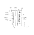
- FIG. 1 is a perspective view showing the arrangement of an exposure apparatus according to the first embodiment.
- the exposure apparatus EX is formed on a mask stage MST that supports a mask M, a substrate stage PST that supports a photosensitive substrate P, an illumination optical system IL that illuminates the mask M with exposure light EL, and a mask M.
- the photosensitive substrate P is, for example, a glass substrate coated with a photosensitive agent (photoresist), and a transfer pattern is formed in the photosensitive agent.
- the projection optical system PL is composed of a plurality (seven) of projection optical modules PLa to PLg arranged in parallel.
- the exposure apparatus EX in the present embodiment includes a mask M and a photosensitive substrate P with respect to the projection optical system PL.
- the mask M is illuminated with the exposure light EL while moving synchronously (synchronous scanning), and the pattern image of the mask M is transferred to the photosensitive substrate P.
- the synchronous movement direction (scanning direction) between the mask M and the photosensitive substrate P is the X-axis direction
- the direction orthogonal to the scanning direction in the horizontal plane is the Y-axis direction (non-scanning direction)
- the X-axis direction is taken as the Z-axis direction.
- the directions around the X-axis, Y-axis, and Z-axis are the ⁇ X, ⁇ Y, and ⁇ Z directions, respectively.
- the mask stage MST is movable in the X-axis direction, the Y-axis direction, the Z-axis direction, and the ⁇ Z direction, and is driven by a mask stage drive unit MSTD configured by a linear motor or the like under the control of the control device CONT.
- the exposure light EL that has passed through the mask M is incident on the projection optical modules PLa to PLg, respectively.
- the projection optical modules PLa to PLg are supported on the surface plate 150, and form a pattern image corresponding to the irradiation area on the mask M by the exposure light EL on the photosensitive substrate P.
- the projection optical modules PLa, PLc, PLe, and PLg and the projection optical modules PLb, PLd, and PLf are arranged in the Y-axis direction, respectively.
- the rows of the projection optical modules PLa, PLc, PLe, and PLg and the rows of the projection optical modules PLb, PLd, and PLf are arranged apart from each other in the X axis direction, and are arranged in a staggered manner along the Y axis direction as a whole.
- Each of the projection optical modules PLa to PLg has a plurality of optical elements (lenses and the like).
- the exposure light EL transmitted through the projection optical modules PLa to PLg forms a pattern image corresponding to the irradiation area on the mask M for each of the different projection areas 50a to 50g on the photosensitive substrate P.
- the substrate stage PST has a substrate holder PH, and holds the photosensitive substrate P via the substrate holder PH. Similar to mask stage MST, substrate stage PST is movable in the X-axis direction, Y-axis direction, and Z-axis direction, and is also movable in the ⁇ X, ⁇ Y, and ⁇ Z directions.
- the substrate stage PST is driven by a substrate stage drive unit PSTD configured by a linear motor or the like under the control of the control device CNTO.
- a focus detection system 110 that detects the position of the surface in the Z-axis direction is provided.
- the focus detection system 110 is configured by arranging a plurality of oblique incidence type focus detection systems, for example.
- the detection result of the focus detection system 110 is output to the control device CONT, and the control device CONT has a predetermined distance and parallel between the pattern surface of the mask M and the exposure surface of the photosensitive substrate P based on the detection result of the focus detection system 110. Control to make a degree.
- the control device CONT is connected to the storage unit 80, and monitors the positions of the mask stage MST and the substrate stage PST based on recipe information stored in the storage unit 80, and the substrate stage drive unit PSTD and the mask. By controlling the stage drive unit MSTD, the mask M and the photosensitive substrate P are moved synchronously in the X-axis direction.
- FIG. 2 is a diagram showing the configuration of the illumination optical system IL and the projection optical system PL.
- the illumination optical system IL includes a light source 1 composed of an ultra-high pressure mercury lamp or the like, an elliptical mirror 1a that condenses light emitted from the light source 1, and light collected by the elliptical mirror 1a.
- the dichroic mirror 2 that reflects light having a wavelength necessary for exposure and transmits light having other wavelengths, and the wavelength necessary for exposure among light reflected by the dichroic mirror 2 (usually g, h, i
- a wavelength selection filter 3 that passes light including only at least one band of lines) as exposure light, and a plurality of exposure lights from the wavelength selection filter 3 (seven in this embodiment) are branched into reflection mirrors.
- a light guide 4 that is incident on each of the illumination system modules IMa to IMg via a light source 5 is provided.
- the illumination system module IM constituting the illumination optical system IL in the present embodiment, seven illumination system modules IMa to IMg are provided corresponding to the projection optical modules PLa to PLg.
- each of the illumination system modules IMa to IMg is arranged corresponding to each of the projection optical modules PLa to PLg with a predetermined interval in the X axis direction and the Y axis direction.
- the exposure light EL emitted from each of the illumination system modules IMa to IMg illuminates different irradiation areas on the mask M in correspondence with the projection optical modules PLa to PLg.
- Each of the illumination system modules IMa to IMg includes an illumination shutter 6, a relay lens 7, a fly-eye lens 8 as an optical integrator, and a condenser lens 9.
- the illumination shutter 6 is disposed on the downstream side of the light path of the light guide 4 so as to be detachable from the light path.
- the illumination shutter 6 shields the exposure light when it is arranged in the optical path, and cancels the shielding when retracted from the optical path.
- a shutter drive unit 6 a that drives the illumination shutter 6 is connected to the illumination shutter 6.
- the shutter driving unit 6a is controlled by the control device CONT.
- each of the illumination system modules IMa to IMg is provided with a light amount adjusting mechanism 10.
- the light amount adjusting mechanism 10 adjusts the exposure amount by setting the illuminance of the exposure light for each optical path, and includes a half mirror 11, a detector 12, a filter 13, and a filter driving unit 14. Yes.
- the half mirror 11 is disposed in the optical path between the filter 13 and the relay lens 7, and causes a part of the exposure light transmitted through the filter 13 to enter the detector 12.
- the detector 12 independently detects the illuminance of the incident exposure light, and outputs the detected illuminance signal to the control device CONT.
- the filter 13 is formed so that the transmittance gradually changes linearly in a predetermined range along the X-axis direction, for example, and is disposed between the illumination shutter 6 and the half mirror 11 in each optical path.
- the filter drive unit 14 adjusts the exposure amount for each optical path by moving the filter 13 along the X-axis direction based on an instruction from the control device CONT.
- the light beam that has passed through the light amount adjusting mechanism 10 reaches the fly-eye lens 8 through the relay lens 7.
- the fly-eye lens 8 forms a secondary light source on the exit surface side, and the exposure light EL from the secondary light source passes through the condenser lens 9 and includes a right-angle prism 16, a lens system 17, and a concave mirror 18. After passing through the catadioptric optical system 15, the irradiation area on the mask M is illuminated uniformly.
- Each of the projection optical modules PLa to PLg includes an image shift mechanism 19, a focus position adjustment mechanism 31, two sets of catadioptric optical systems 21 and 22, a field stop 20, a blind 30, and a magnification adjustment mechanism 23. It has.
- the image shift mechanism 19 shifts the pattern image of the mask M in the X-axis direction or the Y-axis direction, for example, by rotating two parallel flat plate glasses in the ⁇ Y direction or the ⁇ X direction, respectively.
- the focus position adjusting mechanism 31 includes, for example, a pair of wedge prisms, and changes the image plane position of the pattern image by changing the total thickness of the wedge prisms in the optical path. The tilt angle of the image plane of the pattern image is changed by rotating around the optical axis.
- the exposure light EL that has passed through the mask M passes through the image shift mechanism 19 and the focus position adjustment mechanism 31 and then enters the first set of catadioptric optical system 21.
- the catadioptric optical system 21 forms an intermediate image of the pattern of the mask M, and includes a right-angle prism 24, a lens system 25, and a concave mirror 26.
- the right-angle prism 24 is rotatable in the ⁇ Z direction, and the pattern image of the mask M can be rotated.
- the field stop 20 and the blind 30 are arranged on the image plane of the intermediate image formed by the catadioptric optical system 21 or in the vicinity thereof.
- the field stop 20 sets a projection area on the photosensitive substrate P as described later.
- the exposure light EL transmitted through the field stop 20 enters the second set of catadioptric optical system 22.
- the catadioptric optical system 22 includes a right-angle prism 27, a lens system 28, and a concave mirror 29.
- the right-angle prism 27 is also rotatable in the ⁇ Z direction, and the pattern image of the mask M can be rotated.
- the exposure light EL emitted from the catadioptric optical system 22 passes through the magnification adjusting mechanism 23 and forms a pattern image of the mask M on the photosensitive substrate P at an erecting equal magnification.
- the magnification adjusting mechanism 23 is configured by, for example, arranging a first plano-convex lens, a biconvex lens, and a second plano-convex lens in this order along the Z axis, and by moving the biconvex lens in the Z axis direction, the pattern of the mask M Change the magnification of the image.
- a detector (light detection device) 41 is disposed on the substrate stage PST.
- the detector 41 detects, for example, illuminance as information relating to the exposure amount of the exposure light EL applied to the photosensitive substrate P, and outputs the detection result to the control device CONT.
- the detector 41 can be installed at the same level as the photosensitive substrate P by a mechanism (not shown), and can be moved in the X-axis direction and the Y-axis direction.
- a pattern image detection sensor 70 provided with a reference member 70a having a predetermined reference mark is provided at the ⁇ X side end in the scanning direction of the substrate stage PST.
- the reference member 70a is set so that the height of the reference mark in the Z-axis direction substantially coincides with the surface (exposure surface) of the photosensitive substrate P.
- the pattern image detection sensor 70 is provided so as to be movable in the X-axis direction and the Y-axis direction by a mechanism (not shown).
- the pattern image detection sensor 70 detects an aerial image as a pattern image of a predetermined pattern (measurement mark) provided on the mask M via the reference mark on the reference member 70a, and outputs the detection result to the control device CONT. .
- FIG. 3 is a diagram showing the field stop 20 and the blind 30 provided in the projection optical system PL.
- the field stop 20 and the blind 30 are disposed at a position substantially conjugate with the mask M and the photosensitive substrate P, and are provided in the blind unit 120 attached to the surface plate 150.
- one blind unit 120 is provided for each column of ⁇ X side projection optical modules PLa, PLc, PLe, and PLg and each column of + X side projection optical modules PLb, PLd, and PLf.
- the field stop 20 is provided for each of the projection optical modules PLa to PLg, and the projection regions 50a to 50g of the projection optical modules PLa to PLg on the photosensitive substrate P are formed in the corresponding field stop 20, respectively.
- each opening K is formed in an isosceles trapezoidal shape having two sides parallel to the Y-axis direction, or a trapezoidal shape having two sides parallel to the Y-axis direction and one side parallel to the X-axis direction.
- the projection areas 50a to 50g are set in a trapezoidal shape having a conjugate relationship with the corresponding opening K.
- the blind 30 is a parallelogram-shaped plate member having two sides parallel to the X-axis and Y-axis directions, and each hypotenuse of the blind 30 is formed in parallel with any hypotenuse of the opening K.
- the blind 30 is movable in the X-axis direction and the Y-axis direction within the blind unit 120 by a drive mechanism (not shown), and at least a part of each optical path of one or more projection optical modules among the projection optical modules PLa to PLg. Can be appropriately shielded.
- the blind 30 can block at least a part of the exposure light EL in the corresponding projection optical module, and can change the effective size of the projection area.
- the blind 30 can set and change the width of the corresponding projection area in the Y-axis direction.
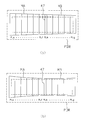
- FIG. 4 is a plan view showing projection areas 50a to 50g on the photosensitive substrate P.
- the projection areas 50a to 50g are adjacent to each other in the Y-axis direction, that is, end parts 51a and 51b, end parts 51c and 51d, end parts 51e and 51f, end parts 51g and 51h, and end parts 51i and 51j.
- the end portions 51k and 51l are set to overlap in the Y-axis direction. For this reason, by performing exposure (scanning exposure) while scanning the photosensitive substrate P in the X-axis direction with respect to the projection areas 50a to 50g, overlapping areas 52a to 52f (double exposure) overlapped (see FIG. 4 is formed between the two-dot difference lines.
- the ⁇ X side blind 30 moves in the Y direction and is effective in at least one of the ⁇ X side projection regions 50a, 50c, 50e, and 50g. Set the appropriate size. Further, the + X side blind 30 is also moved in the Y direction, and the effective size of at least one of the + X side projection areas 50b, 50d, and 50f is appropriately set.
- the blind image Y of the pattern image of the mask M transferred through the projection regions 50a to 50g is used.
- the width in the axial direction can be set as appropriate, and the pattern width in the Y-axis direction of the transfer pattern formed on the photosensitive substrate P as a latent image corresponding to the pattern image can be set as appropriate. Note that the projection area positioned outside the pattern width of the transfer pattern set by the blind 30 is shielded by a blind mechanism (not shown) or the supply of the exposure light EL from the illumination optical system IL is stopped.
- the joint portions 47 are formed by overlappingly exposing the boundary portions of the transfer patterns MA and MB corresponding to the boundary portions 45 and 46 of the partial patterns PA and PB, respectively.
- the entire transfer pattern MPA on the photosensitive substrate P is a combination of the transfer pattern MA of the partial pattern PA and the transfer pattern MB of the partial pattern PB.
- the transfer pattern MA is formed using the projection optical modules PLa to PLf among the projection optical modules PLa to PLg.
- the transfer pattern MB is used using the projection optical modules PLb to PLg. Shall be formed.
- the joint portion 47A in the transfer pattern MA is formed using the projection optical module PLf
- the joint portion 47B in the transfer pattern MB is formed using the projection optical module PLb.
- the range of the projection optical module used for each of the first and second scanning exposures and the pattern width in the Y-axis direction of the transfer patterns MA and MB are set before each scanning exposure using the blind 30 and a blind mechanism (not shown). Is done.
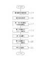
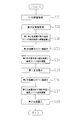
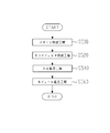
- the control device CONT acquires illuminance information in each of the projection areas 50a to 50g and stores it in the storage unit 80 (step S10).
- step S10 the control device CONT sequentially moves the detector 41 into the projection areas 50a to 50g, detects the illuminance of the exposure light EL in the projection areas 50a to 50g, and acquires the detection result as illuminance information.
- the control device CONT acquires illuminance information indicating the illuminance of the end portions 51a to 51l of the projection regions 50a to 50g, for example.
- the control apparatus CONT acquires the illumination information shown in FIG. 7A, for example.
- the control device CONT adjusts the light amount of each of the illumination system modules IMa to IMg.
- the mechanism 10 is adjusted and corrected within the illuminance range ILR, and illuminance information indicating the correction result is acquired.
- the control device CONT acquires illuminance information input from an input device (not shown) (for example, a keyboard or a data communication device) instead of acquiring the illuminance information detected by the detector 41, and stores the illuminance information. 80 can also be stored. Alternatively, exposure energy information calculated based on illuminance information can be acquired and stored in the storage unit 80.
- an input device for example, a keyboard or a data communication device
- exposure energy information calculated based on illuminance information can be acquired and stored in the storage unit 80.
- the control device CONT obtains joint information, which is information relating to the joint portions 47 of the transfer patterns MA and MB, from recipe information stored in the storage unit 80 in advance (step S11). Specifically, the control device CONT acquires information indicating the projection optical module PLf corresponding to the joint 47A of the transfer pattern MA and the projection optical module PLb corresponding to the joint 47B of the transfer pattern MB as joint information. To do.
- the control device CONT masks the first and second scanning exposures based on the exposure amount characteristic information such as illuminance information or exposure energy information stored in step S10 and the joint information acquired in S11.
- the scanning speeds of the stage MST and the substrate stage PST are derived (step S12).
- the control device CONT has a scanning speed that brings the exposure energy difference between the transfer patterns MA and MB in the joint portion 47 within a predetermined energy difference range, and the projection areas 50a to 50f corresponding to the first scanning exposure and A scanning speed for deriving the exposure energy value exposed by each of the projection areas 50b to 50g corresponding to the second scanning exposure within a predetermined energy value range IER (see FIG. 7B) is derived.
- control device CONT derives the scanning speed using a predetermined arithmetic expression or a lookup table based on the exposure amount characteristic information and the joint information.
- the exposure energy corresponds to the integrated exposure amount per unit area on the photosensitive substrate P by one scanning exposure.
- the control device CONT sets the position of the blind 30 when performing the first scanning exposure, and sets the pattern width of the transfer pattern MA (step S13). That is, the ⁇ X side blind 30 is disposed so as to shield the projection area 50g, and the + X side blind 30 is retracted from the projection areas 50b, 50d, and 50f. Then, the control device CONT aligns the photosensitive substrate P placed on the substrate stage PST and the mask M placed on the mask stage MST, and the substrate stage PST and the mask at the scanning speed derived in step S12. The first scanning exposure is performed by moving the stage MST in the X-axis direction synchronously (step S14). As a result, a transfer pattern MA is formed on the photosensitive substrate P as shown in FIG.
- the control device CONT sets the position of the blind 30 when performing the second scanning exposure, and sets the pattern width of the transfer pattern MB (step S15). That is, the ⁇ X side blind 30 is arranged so as to shield the projection area 50a, and the + X side blind 30 is arranged so as to shield a part of the projection area 50b on the + Y side. Subsequently, the control device CONT moves the substrate stage PST stepwise in the non-scanning direction and aligns the mask M with the photosensitive substrate P. That is, alignment is performed so that the joint 47B of the transfer pattern MB formed by the second scanning exposure is superimposed on the joint 47A of the transfer pattern MA formed by the first scanning exposure.
- control device CONT performs the second scanning exposure by synchronously moving the mask M and the photosensitive substrate P in the X-axis direction at the scanning speed derived in step S12 (step S16).
- a transfer pattern MB is formed on the photosensitive substrate P as shown in FIG.
- the transfer patterns MA and MB are formed on the photosensitive substrate P by joining them together, so that a single mask M is used, which is larger than the transfer pattern corresponding to the pattern PPA provided on the mask M.
- a transfer pattern MPA can be formed on the photosensitive substrate P.
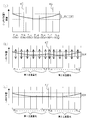
- the exposure energy distribution as shown in FIG. 7B can be corrected to the exposure energy distribution as shown in FIG. 7C.
- FIG. 7B shows the exposure energy distribution when the first and second scanning exposures are performed at the same scanning speed based on the illuminance information shown in FIG. ) Shows the exposure energy distribution when the first and second scanning exposures are performed based on the scanning speed derived in step S12.
- the exposure energy distribution in the first and second scanning exposures that is, the exposure energy distribution of the entire transfer patterns MA and MB is set within a predetermined exposure energy value range IER.
- the exposure energy difference between the transfer patterns MA and MB at the joint portion 47 within a predetermined energy difference range
- the pattern line width of the entire transfer pattern MPA can be within a desired line width range, and the joint portion. 47, the occurrence of a line width difference between the pattern line widths of the transfer patterns MA and MB can be suppressed. Therefore, when a device such as a liquid crystal display device is manufactured using the exposure method and exposure apparatus of the first embodiment, a large device corresponding to the transfer pattern MPA can be manufactured satisfactorily.
- the scanning speeds of the first and second scanning exposures are derived based on the exposure amount characteristic information and the joint information. It is also possible to derive only one scanning speed of scanning exposure and set the other scanning speed to a preset scanning speed.
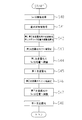
- control device CONT performs steps S20 and S21 in the same manner as steps S10 and S11 in the first embodiment.
- the control device CONT stores the exposure amount characteristic information as shown in FIG. 9A in the storage unit 80, for example.
- the control device CONT sets each exposure energy distribution in the first and second scanning exposures based on the exposure amount characteristic information stored in step S20 and the joint information acquired in step S21.
- An adjustment amount (operation amount) of at least one of the light amount adjustment mechanism 10 and the condenser lens 9 of the projection optical module is derived (step S22).
- the control device CONT adjusts the exposure energy difference between the transfer patterns MA and MB in the joint portion 47 within a predetermined energy difference range, and includes projection areas 50a to 50f corresponding to the first scanning exposure and An adjustment amount for deriving the exposure energy value exposed by each of the projection areas 50b to 50g corresponding to the second scanning exposure within a predetermined energy value range IER (see FIG. 9B) is derived.
- the control device CONT adjusts so that the illuminance adjustment value of the projection optical module close to the joint portion 47 is greater than or equal to the illuminance adjustment value of the projection optical module separated from the joint portion 47. Is derived.
- the control device CONT sets the pattern width of the transfer pattern MA, similarly to step S13 in the first embodiment (step S23). Then, the alignment between the photosensitive substrate P and the mask M is performed, and at least one of the light quantity adjusting mechanisms 10 and the condenser lens 9 is operated based on the adjustment amount derived in step S22, and the illuminance and the projection areas 50a to 50f At least one of the illuminance distributions is adjusted (step S24).
- the adjustment of the illuminance of each of the projection areas 50a to 50f is performed by the light amount adjusting mechanism 10 of each of the illumination system modules IMa to IMf. This is performed by tilting the condenser lens 9 of the illumination system modules IMa to IMf.
- the controller CONT performs first scanning exposure (step S25), and forms a transfer pattern MA on the photosensitive substrate P as shown in FIG.
- control device CONT sets the pattern width of the transfer pattern MB, similarly to step S15 in the first embodiment (step S26). Then, the substrate stage PST is moved stepwise in the non-scanning direction, and the mask M and the photosensitive substrate P are aligned. Subsequently, similarly to step S24, the control device CONT operates at least one of the light quantity adjustment mechanisms 10 and the condenser lens 9 based on the adjustment amount derived in step S22, and the illuminance and illuminance of each projection region 50b to 50g. At least one of the distributions is adjusted (step S27). Thereafter, second scanning exposure is performed (step S28), and a transfer pattern MB is formed on the photosensitive substrate P as shown in FIG. In this way, the transfer pattern MPA can be formed on the photosensitive substrate P.
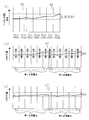
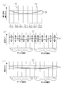
- the exposure energy distribution as shown in FIG. 9B can be corrected to the exposure energy distribution as shown in FIG. 9C.
- FIG. 9B shows each scanning exposure without adjusting the illuminance or the illuminance distribution between the first and second scanning exposures based on the exposure amount characteristic information shown in FIG.
- FIG. 9C shows the exposure energy distribution when performing the first and second scanning exposures based on the illuminance distribution corrected based on the adjustment amount derived at step S22.
- the pattern line width of the entire transfer pattern MPA can be set within a desired line width range and the joint 47 can be used as in the first embodiment. Generation of a line width difference between the pattern line widths of the transfer patterns MA and MB can be suppressed.
- the exposure method according to the third embodiment is performed by the same procedure as the exposure procedure shown in FIG. However, it is assumed that the control device CONT stores the exposure amount characteristic information as shown in FIG.
- step S22 the control device CONT uses the adjustment amount of each light quantity adjustment mechanism 10 corresponding to the adjustment value of the illuminance of each projection area 50a to 50f in the first scanning exposure as the distance between the transfer patterns MA and MB in the joint portion 47.
- An adjustment amount is derived so that a value of 1 ⁇ 2 of the illuminance difference between the projection areas 50a to 50f is approximately evenly allocated.
- the adjustment amount of each light quantity adjustment mechanism 10 corresponding to the adjustment value of the illuminance of each projection region 50b to 50g in the second scanning exposure is 1 ⁇ 2 of the illuminance difference between the transfer patterns MA and MB in the joint portion 47.
- An adjustment amount is derived so that the value is substantially evenly allocated to the illuminance of each of the projection areas 50b to 50g.
- the exposure energy distribution as shown in FIG. 10B can be corrected to the exposure energy distribution as shown in FIG. 10C.
- FIG. 10B shows each scanning exposure without adjusting the illuminance or illuminance distribution between the first and second scanning exposures based on the exposure amount characteristic information shown in FIG.
- FIG. 10C shows the exposure energy distribution when performing the first and second scanning exposures based on the illuminance distribution corrected based on the adjustment amount derived in step S23.
- the pattern line width in the entire transfer pattern MPA can be within a desired line width range, as in the first and second embodiments. Generation of a line width difference between the pattern line widths of the transfer patterns MA and MB in the portion 47 can be suppressed.
- the control device CONT has focus position information indicating the distribution of the focus positions (focusing positions) of the projection optical modules PLa to PLg, or image plane position information indicating the distribution of the image plane positions.
- control device CONT detects, for example, a spatial image of the measurement mark at each end 51a to 51l of each projection region 50a to 50g, and acquires focus information corresponding to this detection result. Thereby, the control apparatus CONT acquires the focus information shown in FIG.
- each projection optical module PLa to PLg When the focus position of each projection optical module PLa to PLg is not within the focus position range FOR (see 12 (a)) as a predetermined allowable range, the control device CONT applies to each projection optical module PLa to PLg.
- the focus position adjustment mechanism 31 provided is adjusted and corrected within the focus position range FOR, and focus information indicating the correction result is acquired.
- step S30 the control device CONT acquires focus information input from an input device (not shown) and stores it in the storage unit 80 instead of acquiring focus information detected using the pattern image detection sensor 70. You can also.
- the control device CONT obtains joint information, which is information related to the joint portions 47 of the transfer patterns MA and MB, from recipe information stored in the storage unit 80 in advance. Obtain (step S31).
- the control device CONT adjusts the tilt angle as the operation amount of the substrate stage PST in the first and second scanning exposures based on the focus information stored in step S30 and the joint information acquired in S31.
- a value is derived (step S32).
- the control device CONT is an adjustment value that brings the difference in focus position (focus difference) between the transfer patterns MA and MB at the joint 47 into a predetermined focus difference range, and is a projection corresponding to the first scanning exposure.
- An adjustment value that brings the focus position in each of the projection areas 50a to 50f and the projection areas 50b to 50g corresponding to the second scanning exposure into a predetermined focus position range FOR is derived.
- the control device CONT derives an adjustment value based on the focus information and the joint information using a predetermined arithmetic expression or a lookup table.
- control device CONT sets the pattern width of the transfer pattern MA, similarly to step S13 in the first embodiment (step S33). Then, the photosensitive substrate P and the mask M are aligned, the substrate stage PST is operated based on the adjustment value derived in step S32, the inclination angle is adjusted (step S34), and the first scanning exposure is performed (step S34). Step S35). As a result, a transfer pattern MA is formed on the photosensitive substrate P as shown in FIG.
- control device CONT sets the pattern width of the transfer pattern MB, similarly to step S15 in the first embodiment (step S36). Then, the substrate stage PST is moved stepwise in the non-scanning direction to align the photosensitive substrate P and the mask M. Subsequently, similarly to step S34, the controller CONT operates the substrate stage PST based on the adjustment value derived in step S32, adjusts the tilt angle (step S37), and performs the second scanning exposure (step). S38). In this way, the transfer pattern MPA can be formed on the photosensitive substrate P.
- a focus position distribution as shown in FIG. 12B can be corrected to a focus position distribution as shown in FIG.
- FIG. 12B shows each scanning exposure based on the focus information shown in FIG. 12A without adjusting the tilt angle of the substrate stage PST between the first and second scanning exposures.
- FIG. 12C shows the focus position distribution when performing the first and second scanning exposures based on the tilt angle of the substrate stage PST corrected based on the adjustment value derived in step S32.
- the focus position distribution is shown.
- the focus position distributions shown in FIGS. 12B and 12C show the focus position distributions based on the exposure surface (pattern transfer surface) of the photosensitive substrate P placed on the substrate stage PST.
- the focus position distribution in the first and second scanning exposures that is, the focus position distribution of the entire transfer patterns MA and MB is set within a predetermined focus position range FOR.
- the pattern line width of the entire transfer pattern MPA can be within a desired line width range. The occurrence of a line width difference between the pattern line widths of the transfer patterns MA and MB can be suppressed.
- the substrate stage PST is based on the focus information indicating the focus position distribution along the Y-axis direction of each of the projection optical modules PLa to PLg.
- the adjustment value of the tilt angle is derived, but based on the focus position distribution indicating the focus position distribution at a plurality of positions in the X-axis direction, that is, the two-dimensional focus position distribution along the XY plane, the substrate stage It is also possible to derive a dynamic adjustment value of the tilt angle of the PST and sequentially adjust the tilt angle of the substrate stage PST during the first and second scanning exposures.
- the pattern image detection sensor 70 and the focus detection system 110 cooperate to detect the focus information of each projection optical module PLa to PLg over the scanning range in the X-axis direction of the substrate stage PST. Can be obtained by doing.
- control device CONT performs steps S40 and S41 in the same manner as steps S30 and S31 in the fourth embodiment.
- the control device CONT stores the focus information as shown in FIG.
- the control device CONT determines the focus positions of the projection optical modules PLa to PLg in the first and second scanning exposures.
- An adjustment amount (operation amount) of the focus position adjustment mechanism 31 that adjusts the image plane position and the image plane tilt angle of each projection optical module PLa to PLg is derived as an adjustment value (step S42).
- the control device CONT is an adjustment amount that brings the focus difference between the transfer patterns MA and MB in the joint portion 47 into a predetermined focus difference range, and the projection regions 50a to 50f corresponding to the first scanning exposure and the first An adjustment amount for deriving the focus position in each of the projection areas 50b to 50g corresponding to the two-scan exposure within the predetermined focus position range FOR is derived.
- the adjustment value of the image plane position of the projection optical module close to the joint portion 47 is greater than or equal to the adjustment value of the image plane position of the projection optical module separated from the joint portion 47.
- the adjustment amount is derived as follows.
- control device CONT sets the pattern width of the transfer pattern MA, similarly to step S13 in the first embodiment (step S43). Then, the photosensitive substrate P and the mask M are aligned, and the focus positions of the projection optical modules PLa to PLf are adjusted by operating the focus position adjustment mechanisms 31 based on the adjustment amounts derived in step S42. (Step S44). Thereafter, the controller CONT performs first scanning exposure (step S45), and forms a transfer pattern MA on the photosensitive substrate P as shown in FIG.
- control device CONT sets the pattern width of the transfer pattern MB, similarly to step S15 in the first embodiment (step S46). Then, the control device CONT moves the substrate stage PST stepwise in the non-scanning direction, aligns the photosensitive substrate P and the mask M, and sets the focus positions of the projection optical modules PLb to PLg in the same manner as in step S44. Adjustment is performed by operating each focus position adjustment mechanism 31 based on the adjustment amount derived in step S42 (step S47). Thereafter, the controller CONT performs second scanning exposure (step S48), and forms a transfer pattern MB on the photosensitive substrate P as shown in FIG. In this way, the transfer pattern MPA can be formed on the photosensitive substrate P.
- the focus position distribution as shown in FIG. 14B can be corrected to the focus position distribution as shown in FIG. 14C.
- the focus position adjusting mechanism 31 of each projection optical module is adjusted between the first and second scanning exposures based on the focus information shown in FIG.
- FIG. 14C shows the focus position distribution when each scanning exposure is performed, and FIG. 14C is based on the image plane position and the image plane tilt angle of each projection optical module corrected based on the adjustment amount derived in step S42.
- the focus position distribution when performing first and second scanning exposures is shown.
- the pattern line width of the entire transfer pattern MPA can be set within a desired line width range and the joint 47 can be used as in the fourth embodiment. Generation of a line width difference between the pattern line widths of the transfer patterns MA and MB can be suppressed.
- the dynamic adjustment amount of each focus position adjustment mechanism 31 during scanning exposure is derived based on the two-dimensional focus information along the XY plane. During the first and second scanning exposures, it is possible to sequentially adjust at least one of the image plane position and the image plane tilt angle of the corresponding projection optical module.
- the exposure method according to the sixth embodiment is performed by the same procedure as the exposure procedure shown in FIG. However, it is assumed that the control device CONT stores the focus information as shown in FIG.
- step S42 the control device CONT uses the transfer pattern MA in the joint 47 as the adjustment amount of each focus position adjustment mechanism 31 corresponding to the adjustment value of the focus position of each projection optical module PLa to PLf in the first scanning exposure.
- An adjustment amount is derived so that a value that is 1 ⁇ 2 of the difference in the focus position between MBs is allocated approximately evenly to the focus positions of the projection optical modules PLa to PLf.
- the adjustment amount of each focus position adjustment mechanism 31 corresponding to the adjustment value of the focus position of each projection optical module PLb to PLg in the second scanning exposure the difference in the focus position between the transfer patterns MA and MB in the joint portion 47 is obtained.
- An adjustment amount is derived so that a value of 1/2 is allocated substantially evenly to the focus positions of the projection optical modules PLb to PLg.
- the focus position distribution as shown in FIG. 15B can be corrected to the focus position distribution as shown in FIG. 15C.
- the focus position adjustment mechanism 31 of each projection optical module is adjusted between the first and second scanning exposures based on the focus information shown in FIG.
- FIG. 15C shows the focus position distribution when performing each scanning exposure
- FIG. 15C is based on the image plane position and the image plane tilt angle of each projection optical module corrected based on the adjustment amount derived in step S42.
- the focus position distribution when performing first and second scanning exposures is shown.
- the pattern line width in the entire transfer pattern MPA can be set within a desired line width range as in the fourth and fifth embodiments. Generation of a line width difference between the pattern line widths of the transfer patterns MA and MB in the portion 47 can be suppressed.
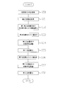
- the control device CONT acquires information on the initial transfer position (transfer characteristic information) and stores it in the storage unit 80 (step S50).
- the initial transfer position is measured by a long dimension measuring device whose absolute dimensions are managed using the photosensitive substrate P developed or etched after the trial exposure, and the outer peripheral portion (and necessary if necessary) of the transfer pattern corresponding to the pattern PPA. Accordingly, the measurement is performed by measuring the misalignment of the transfer pattern by measuring the measurement mark in the center).
- the positional deviation amount of the transfer pattern thus measured is input from an input unit (not shown) and stored in the storage unit 80.
- the control device CONT acquires the joint information as in step S21 in the first embodiment (step S51).
- FIG. 17A shows the initial transfer characteristics of the transfer pattern stored in the storage unit 80 in step S51.
- the control device CONT performs the first and second scans so that the positional deviation amount at the joint 47 between the transfer pattern MA in the first scanning exposure and the transfer pattern MB in the second scanning exposure falls within a predetermined positional deviation range.
- Adjustment amounts (operation amounts) of the image shift mechanism 19, the magnification adjustment mechanism 23, the right-angle prisms 24 and 27, etc. for adjusting the imaging characteristics of the projection optical modules PLa to PLg in exposure are calculated using the method of least squares or the like. Derived (step S52).
- the control device CONT adjusts the imaging characteristics of the projection optical modules PLa to PLf in the first scanning exposure so that the positional deviation amount at the joint 47 over the scanning range of the scanning exposure falls within a predetermined positional deviation range.
- Values and adjustment values of the imaging characteristics of the projection optical modules PLb to PLg in the second scanning exposure are calculated, and adjustments of the image shift mechanism 19, the magnification adjustment mechanism 23, the right-angle prisms 24, 27, etc. corresponding to the adjustment values are calculated. Deriving the quantity.
- the adjustment amount is derived so that the entire peripheral portion of the transfer pattern MA and the transfer pattern MB is within a predetermined misalignment range FDR as an allowable range as shown in FIG.
- the control device CONT sets the pattern width of the transfer pattern MA, similarly to step S13 in the first embodiment (step S53). Then, the photosensitive substrate P and the mask M are aligned, and the imaging characteristics of the projection optical modules PLa to PLf are adjusted based on the adjustment amount derived in step S52 (step S54). At this time, adjustment is performed by operating at least one of the image shift mechanism 19, the magnification adjustment mechanism 23, and the right-angle prisms 24 and 27 of the projection optical modules PLa to PLf. Further, in the first scanning exposure, by sequentially operating the adjustment mechanisms of the projection optical modules PLa to PLf based on the adjustment amounts derived in step S52, the transfer pattern is formed on the photosensitive substrate P as shown in FIG. MA is formed (step S55).
- control device CONT sets the pattern width of the transfer pattern MB, similarly to step S15 in the first embodiment (step S56). Then, the control device CONT aligns the mask M with the photosensitive substrate P, and sets the imaging characteristics of the projection optical modules PLb to PLg based on the adjustment amounts derived in step S52, as in step S54. Adjustment is performed by operating the adjustment mechanism (step S57). Further, in the second scanning exposure, by sequentially operating the adjustment mechanisms of the projection optical modules PLb to PLg based on the adjustment amount derived in step S52, the transfer pattern on the photosensitive substrate P as shown in FIG. MB is formed (step S58). In this way, the transfer pattern MPA can be formed on the photosensitive substrate P.
- step S52 when the adjustment amount of each adjustment mechanism is derived so as to linearly correct the correction of the displacement amount of the transfer pattern, a correction result as shown in FIG. 18A is obtained, but nonlinearly.
- a correction result as shown in FIG. 18B can be obtained.
- the pattern line width in the entire transfer pattern MPA can be within a desired line width range, as in the first to sixth embodiments. Generation of a line width difference between the pattern line widths of the transfer patterns MA and MB at the joint portion 47 can be suppressed.
- the case where the displacement of the transfer pattern occurs in the scanning direction (X-axis direction) has been described, but the case where the displacement of the transfer pattern occurs in the non-scanning direction (Y-axis direction). That is, even when there is a gap in the non-scanning direction between the transfer patterns MA and MB transferred onto the photosensitive substrate by the trial exposure, the transfer pattern is misaligned in the scanning direction (X-axis direction). In addition, the displacement of the transfer pattern can be corrected. Further, by performing linear correction and non-linear correction on the transfer pattern, it is possible to correct the transfer patterns MA and MB so as to be rectangular.
- trial exposure is performed to measure the amount of positional deviation of the transfer pattern, and this measurement result is input from the input unit as information on the initial transfer position and stored in the storage unit 80.
- the aerial image corresponding to the pattern PPA may be detected using the pattern image detection sensor 70, and information on the initial transfer position corresponding to the detection result may be stored in the storage unit 80.
- the transfer characteristics of the transfer pattern are adjusted when the transfer patterns are joined. However, the same applies even when the transfer patterns are not joined.
- transfer characteristics can be adjusted for each scanning exposure. When the transfer patterns are joined at a plurality of positions on the plate P, the adjustment amount of the transfer characteristics can be changed (optimized) according to the positions.
- FIG. 19 is a flowchart showing a manufacturing process of a semiconductor device.
- a metal film is deposited on a wafer to be a semiconductor device substrate (step S400), and a photoresist, which is a photosensitive material, is applied onto the deposited metal film (step S400).
- Step S420 the projection image of the pattern provided with the mask is transferred to each shot area on the wafer using the exposure apparatus according to the present invention (step S440: exposure process (illumination process and projection process)), and this transfer is completed.
- step S460 development process
- step S460 development process
- step S480 processing step
- the resist pattern is a photoresist layer in which unevenness having a shape corresponding to the projected image of the pattern transferred by the exposure apparatus according to the present invention is formed, and the recess penetrates the photoresist layer.
- step S480 the wafer surface is processed through this resist pattern.
- the processing performed in step S480 includes at least one of etching of the wafer surface or film formation of a metal film, for example.
- step S440 the exposure apparatus according to the present invention performs pattern transfer using the photoresist-coated wafer as a photosensitive substrate.
- FIG. 20 is a flowchart showing manufacturing steps of a liquid crystal device such as a liquid crystal display element.
- a pattern formation process step S500
- a color filter formation process step S520
- a cell assembly process step S540
- a module assembly process step S560
- step S500 a predetermined pattern such as a circuit pattern and an electrode pattern is formed on a glass substrate coated with a photoresist as a photosensitive substrate using the exposure apparatus according to the present invention.
- an exposure step of transferring the projection image of the pattern provided on the mask to the photoresist layer using the exposure apparatus according to the present invention development of the photosensitive substrate to which the projection image of the pattern has been transferred, That is, a development process for developing the photoresist layer on the glass substrate to form a photoresist layer having a shape corresponding to the projected image of the pattern, and a processing process for processing the glass substrate through the developed photoresist layer; It is included.
- the color filter forming step of step S520 a large number of sets of three dots corresponding to R (Red), G (Green), and B (Blue) are arranged in a matrix, or three of R, G, and B are arranged.
- a color filter is formed by arranging a plurality of stripe filter sets in the horizontal scanning direction.
- a liquid crystal panel (liquid crystal cell) is assembled using the glass substrate on which the predetermined pattern is formed in step S500 and the color filter formed in step S520.
- a liquid crystal panel is formed by injecting liquid crystal between a glass substrate and a color filter.
- various components such as an electric circuit and a backlight for performing the display operation of the liquid crystal panel are attached to the liquid crystal panel assembled in step S540.
- the present invention can be used for an exposure method and an exposure apparatus for transferring a pattern to a photosensitive substrate.
Landscapes
- Physics & Mathematics (AREA)
- General Physics & Mathematics (AREA)
- Engineering & Computer Science (AREA)
- Exposure And Positioning Against Photoresist Photosensitive Materials (AREA)
- Optics & Photonics (AREA)
- Condensed Matter Physics & Semiconductors (AREA)
- Manufacturing & Machinery (AREA)
- Computer Hardware Design (AREA)
- Microelectronics & Electronic Packaging (AREA)
- Power Engineering (AREA)
- Exposure Of Semiconductors, Excluding Electron Or Ion Beam Exposure (AREA)
Abstract
Description
なお、本開示は、2008年1月9日に提出された日本国特許出願2008-2492号に含まれた主題に関し、その開示の全ては、ここに参照事項として明白に組み込まれる。 FIG. 20 is a flowchart showing manufacturing steps of a liquid crystal device such as a liquid crystal display element. As shown in this figure, in the manufacturing process of the liquid crystal device, a pattern formation process (step S500), a color filter formation process (step S520), a cell assembly process (step S540), and a module assembly process (step S560) are sequentially performed. In the pattern forming process of step S500, a predetermined pattern such as a circuit pattern and an electrode pattern is formed on a glass substrate coated with a photoresist as a photosensitive substrate using the exposure apparatus according to the present invention. In this pattern formation step, an exposure step of transferring the projection image of the pattern provided on the mask to the photoresist layer using the exposure apparatus according to the present invention, development of the photosensitive substrate to which the projection image of the pattern has been transferred, That is, a development process for developing the photoresist layer on the glass substrate to form a photoresist layer having a shape corresponding to the projected image of the pattern, and a processing process for processing the glass substrate through the developed photoresist layer; It is included. In the color filter forming step of step S520, a large number of sets of three dots corresponding to R (Red), G (Green), and B (Blue) are arranged in a matrix, or three of R, G, and B are arranged. A color filter is formed by arranging a plurality of stripe filter sets in the horizontal scanning direction. In the cell assembly process in step S540, a liquid crystal panel (liquid crystal cell) is assembled using the glass substrate on which the predetermined pattern is formed in step S500 and the color filter formed in step S520. Specifically, for example, a liquid crystal panel is formed by injecting liquid crystal between a glass substrate and a color filter. In the module assembling process in step S560, various components such as an electric circuit and a backlight for performing the display operation of the liquid crystal panel are attached to the liquid crystal panel assembled in step S540.
Note that the present disclosure relates to the subject matter included in Japanese Patent Application No. 2008-2492 filed on January 9, 2008, the entire disclosure of which is hereby expressly incorporated by reference.
Claims (27)
- 並設された複数の投影光学モジュールを用いて感光基板上に形成される転写パターンの転写特性情報を取得する特性情報取得工程と、
複数の前記転写パターンのうち前記感光基板上で継ぎ合わされる第1転写パターンおよび第2転写パターンの継ぎ部に対応する前記投影光学モジュールを示す継ぎ部情報を取得する継ぎ情報取得工程と、
前記転写パターンの転写特性を変化させる特性調整機構の動作量であって前記継ぎ部における前記第1転写パターンおよび前記第2転写パターンの前記転写特性の特性差を補正する補正動作量を、前記転写特性情報および前記継ぎ部情報をもとに導出する導出工程と、
前記補正動作量に基づいて前記特性調整機構を動作させ、前記第1転写パターンおよび前記第2転写パターンを前記感光基板上に順次形成する転写工程と、
を含むことを特徴とする露光方法。 A characteristic information acquisition step of acquiring transfer characteristic information of a transfer pattern formed on the photosensitive substrate using a plurality of projection optical modules arranged in parallel;
A joint information obtaining step for obtaining joint information indicating the projection optical module corresponding to a joint portion of the first transfer pattern and the second transfer pattern jointed on the photosensitive substrate among the plurality of transfer patterns;
An operation amount of a characteristic adjustment mechanism that changes a transfer characteristic of the transfer pattern, and a correction operation amount that corrects a difference in characteristic of the transfer characteristic between the first transfer pattern and the second transfer pattern at the joint portion. A derivation step for deriving based on the characteristic information and the joint information;
A transfer step of operating the characteristic adjustment mechanism based on the correction operation amount to sequentially form the first transfer pattern and the second transfer pattern on the photosensitive substrate;
An exposure method comprising: - 前記継ぎ部情報に対応する前記投影光学モジュールによって投影されるパターン像の少なくとも一部を遮蔽して前記第1転写パターンおよび前記第2転写パターンの少なくとも一方のパターン幅を設定するパターン幅設定工程を含むことを特徴とする請求項1に記載の露光方法。 A pattern width setting step of setting at least one pattern width of the first transfer pattern and the second transfer pattern by shielding at least a part of the pattern image projected by the projection optical module corresponding to the joint information. The exposure method according to claim 1, further comprising:
- 前記導出工程は、前記補正動作量として、前記第1転写パターンの前記転写特性を変化させる第1補正動作量と、前記第2転写パターンの前記転写特性を変化させる第2補正動作量との少なくとも一方を導出し、
前記転写工程は、前記第1補正動作量と前記第2補正動作量との少なくとも一方に基づいて前記特性調整機構を動作させ、前記第1転写パターンと前記第2転写パターンとの少なくとも一方に対応する前記転写特性を変化させることを特徴とする請求項1または2に記載の露光方法。 The deriving step includes at least a first correction operation amount for changing the transfer characteristic of the first transfer pattern and a second correction operation amount for changing the transfer characteristic of the second transfer pattern as the correction operation amount. Deriving one,
The transfer step operates the characteristic adjustment mechanism based on at least one of the first correction operation amount and the second correction operation amount, and corresponds to at least one of the first transfer pattern and the second transfer pattern. The exposure method according to claim 1, wherein the transfer characteristic is changed. - 前記導出工程は、前記特性差を示す差分値を所定特性差範囲内にする前記補正動作量を導出することを特徴とする請求項1~3のいずれか一項に記載の露光方法。 4. The exposure method according to claim 1, wherein the deriving step derives the correction operation amount that brings a difference value indicating the characteristic difference within a predetermined characteristic difference range.
- 前記導出工程は、前記転写特性を示す特性値を所定特性値範囲内にする前記補正動作量を導出することを特徴とする請求項4に記載の露光方法。 5. The exposure method according to claim 4, wherein the deriving step derives the correction operation amount that brings a characteristic value indicating the transfer characteristic within a predetermined characteristic value range.
- 前記特性調整機構は、前記投影光学モジュールごとに前記転写特性を変化させ、
前記導出工程は、前記投影光学モジュールごとの前記特性調整機構の動作量を前記補正動作量として導出することを特徴とする請求項1~5のいずれか一項に記載の露光方法。 The characteristic adjustment mechanism changes the transfer characteristic for each projection optical module,
6. The exposure method according to claim 1, wherein the deriving step derives an operation amount of the characteristic adjustment mechanism for each projection optical module as the correction operation amount. - 前記導出工程は、複数の前記投影光学モジュールのうちの第1投影光学モジュールよりも前記継ぎ部に近い第2投影光学モジュールにおける前記転写特性を、前記第1投影光学モジュールにおける前記転写特性に比して同等以上に変化させる前記補正動作量を導出することを特徴とする請求項6に記載の露光方法。 The deriving step compares the transfer characteristic of the second projection optical module closer to the joint than the first projection optical module of the plurality of projection optical modules to the transfer characteristic of the first projection optical module. The exposure method according to claim 6, wherein the correction operation amount that is changed to be equal to or greater than is derived.
- 前記導出工程は、2以上の前記投影光学モジュールにおける前記転写特性を略均等に変化させる前記補正動作量を導出することを特徴とする請求項6に記載の露光方法。 The exposure method according to claim 6, wherein the deriving step derives the correction operation amount that substantially uniformly changes the transfer characteristics in the two or more projection optical modules.
- 前記導出工程は、隣り合う前記投影光学モジュール間における前記転写特性のモジュール間特性差を示す差分値を所定特性差範囲内にする前記補正動作量を導出することを特徴とする請求項6~8のいずれか一項に記載の露光方法。 The deriving step derives the correction operation amount that brings a difference value indicating an inter-module characteristic difference of the transfer characteristic between adjacent projection optical modules within a predetermined characteristic difference range. The exposure method according to any one of the above.
- 前記転写特性は、前記投影光学モジュールを介して前記転写パターンを形成する露光光の露光量を示す露光量特性と、前記投影光学モジュールの像面と前記感光基板とのフォーカス位置を示すフォーカス特性と、の少なくとも一方を含むことを特徴とする請求項1~9のいずれか一項に記載の露光方法。 The transfer characteristic includes an exposure amount characteristic that indicates an exposure amount of exposure light that forms the transfer pattern via the projection optical module, and a focus characteristic that indicates a focus position between the image plane of the projection optical module and the photosensitive substrate. 10. The exposure method according to claim 1, comprising at least one of the following.
- 前記転写工程は、前記感光基板を所定方向へ移動させながら前記第1転写パターンと前記第2転写パターンとを前記感光基板上に形成することを特徴とする請求項1~10のいずれか一項に記載の露光方法。 11. The transfer step includes forming the first transfer pattern and the second transfer pattern on the photosensitive substrate while moving the photosensitive substrate in a predetermined direction. An exposure method according to 1.
- 並設された複数の投影光学モジュールと、
前記複数の投影光学モジュールを用いて感光基板上に形成される転写パターンの転写特性を変化させる特性調整機構と、
前記転写パターンの転写特性情報を記憶した記憶手段と、
複数の前記転写パターンのうち前記感光基板上で継ぎ合わされる第1転写パターンおよび第2転写パターンの継ぎ部に対応する前記投影光学モジュールを示す継ぎ部情報を取得する継ぎ情報取得手段と、
前記特性調整機構の動作量であって前記継ぎ部における前記第1転写パターンおよび前記第2転写パターンの前記転写特性の特性差を補正する補正動作量を、前記転写特性情報および前記継ぎ部情報をもとに導出し、該補正動作量に基づいて前記特性調整機構を動作させ、前記第1転写パターンおよび前記第2転写パターンを前記感光基板上に順次形成する制御を行う制御手段と、
を備えることを特徴とする露光装置。 A plurality of projection optical modules arranged side by side;
A characteristic adjustment mechanism for changing transfer characteristics of a transfer pattern formed on the photosensitive substrate using the plurality of projection optical modules;
Storage means for storing transfer characteristic information of the transfer pattern;
A joint information obtaining unit that obtains joint information indicating the projection optical module corresponding to a joint of the first transfer pattern and the second transfer pattern that are jointed on the photosensitive substrate among the plurality of transfer patterns;
The operation amount of the characteristic adjusting mechanism, which is a correction operation amount for correcting a characteristic difference between the transfer characteristics of the first transfer pattern and the second transfer pattern at the joint, and the transfer characteristic information and the joint information. Control means derived based on and operating the characteristic adjustment mechanism based on the correction operation amount, and performing control to sequentially form the first transfer pattern and the second transfer pattern on the photosensitive substrate;
An exposure apparatus comprising: - 前記継ぎ部情報に対応する前記投影光学モジュールによって投影されるパターン像の少なくとも一部を遮蔽して前記第1転写パターンおよび前記第2転写パターンのパターン幅を設定するパターン幅設定機構を備えることを特徴とする請求項12に記載の露光装置。 A pattern width setting mechanism configured to shield at least a part of a pattern image projected by the projection optical module corresponding to the joint information and set a pattern width of the first transfer pattern and the second transfer pattern; The exposure apparatus according to claim 12, characterized in that:
- 前記制御手段は、前記補正動作量として、前記第1転写パターンの前記転写特性を変化させる第1補正動作量と、前記第2転写パターンの前記転写特性を変化させる第2補正動作量との少なくとも一方を導出し、該第1補正動作量と該第2補正動作量との少なくとも一方に基づいて前記特性調整機構を動作させ、前記第1転写パターンと前記第2転写パターンとの少なくとも一方に対応する前記転写特性を変化させることを特徴とする請求項12または13に記載の露光装置。 The control means includes, as the correction operation amount, at least a first correction operation amount that changes the transfer characteristic of the first transfer pattern and a second correction operation amount that changes the transfer characteristic of the second transfer pattern. One is derived, and the characteristic adjustment mechanism is operated based on at least one of the first correction operation amount and the second correction operation amount, and corresponds to at least one of the first transfer pattern and the second transfer pattern. The exposure apparatus according to claim 12, wherein the transfer characteristic is changed.
- 前記制御手段は、前記特性差を示す差分値を所定特性差範囲内にする前記補正動作量を導出することを特徴とする請求項12~14のいずれか一項に記載の露光装置。 15. The exposure apparatus according to claim 12, wherein the control unit derives the correction operation amount that brings a difference value indicating the characteristic difference within a predetermined characteristic difference range.
- 前記制御手段は、前記転写特性を示す特性値を所定特性値範囲内にする前記補正動作量を導出することを特徴とする請求項15に記載の露光装置。 16. The exposure apparatus according to claim 15, wherein the control means derives the correction operation amount that brings a characteristic value indicating the transfer characteristic within a predetermined characteristic value range.
- 前記特性調整機構は、前記投影光学モジュールごとに前記転写特性を変化させ、
前記制御手段は、前記投影光学モジュールごとの前記特性調整機構の動作量を前記補正動作量として導出することを特徴とする請求項12~16のいずれか一項に記載の露光装置。 The characteristic adjustment mechanism changes the transfer characteristic for each projection optical module,
The exposure apparatus according to any one of claims 12 to 16, wherein the control unit derives an operation amount of the characteristic adjustment mechanism for each projection optical module as the correction operation amount. - 前記制御手段は、複数の前記投影光学モジュールのうちの第1投影光学モジュールよりも前記継ぎ部に近い第2投影光学モジュールにおける前記転写特性を、前記第1投影光学モジュールにおける前記転写特性に比して同等以上に変化させる前記補正動作量を導出することを特徴とする請求項17に記載の露光装置。 The control means compares the transfer characteristic of the second projection optical module closer to the joint than the first projection optical module of the plurality of projection optical modules to the transfer characteristic of the first projection optical module. The exposure apparatus according to claim 17, wherein the correction operation amount that is changed to be equal to or greater than the same is derived.
- 前記制御手段は、2以上の前記投影光学モジュールにおける前記転写特性を略均等に変化させる前記補正動作量を導出することを特徴とする請求項17に記載の露光装置。 18. The exposure apparatus according to claim 17, wherein the control unit derives the correction operation amount that changes the transfer characteristics of the two or more projection optical modules substantially uniformly.
- 前記制御手段は、隣り合う前記投影光学モジュール間における前記転写特性のモジュール間特性差を示す差分値を所定特性差範囲内にする前記補正動作量を導出することを特徴とする請求項17~19のいずれか一項に記載の露光装置。 The control means derives the correction operation amount that brings a difference value indicating a difference in characteristics of the transfer characteristics between adjacent projection optical modules within a predetermined characteristic difference range. The exposure apparatus according to any one of the above.
- 前記感光基板を所定方向へ移動させる走査機構を備え、
前記制御手段は、前記感光基板を前記所定方向へ移動させながら前記第1転写パターンと前記第2転写パターンとを前記感光基板上に形成する制御を行うことを特徴とする請求項12~20のいずれか一項に記載の露光装置。 A scanning mechanism for moving the photosensitive substrate in a predetermined direction;
21. The control unit according to claim 12, wherein the control unit performs control to form the first transfer pattern and the second transfer pattern on the photosensitive substrate while moving the photosensitive substrate in the predetermined direction. The exposure apparatus according to any one of the above. - 前記転写特性は、前記投影光学モジュールを介して前記転写パターンを形成する露光光の露光量を示す露光量特性を含み、
前記特性調整機構は、前記露光量特性を変化させる露光量調整機構を有することを特徴とする請求項12~21のいずれか一項に記載の露光装置。 The transfer characteristic includes an exposure amount characteristic indicating an exposure amount of exposure light that forms the transfer pattern via the projection optical module,
The exposure apparatus according to any one of claims 12 to 21, wherein the characteristic adjustment mechanism includes an exposure amount adjustment mechanism that changes the exposure amount characteristic. - 前記露光量調整機構は、前記照度と前記照度分布との少なくとも一方を変化させる照度調整機構を含むことを特徴とする請求項22に記載の露光装置。 The exposure apparatus according to claim 22, wherein the exposure amount adjustment mechanism includes an illuminance adjustment mechanism that changes at least one of the illuminance and the illuminance distribution.
- 前記感光基板を所定方向へ移動させる走査機構を備え、
前記露光量調整機構は、前記走査機構の前記所定方向への走査速度を変化させる速度調整機構を含むことを特徴とする請求項22に記載の露光装置。 A scanning mechanism for moving the photosensitive substrate in a predetermined direction;
The exposure apparatus according to claim 22, wherein the exposure adjustment mechanism includes a speed adjustment mechanism that changes a scanning speed of the scanning mechanism in the predetermined direction. - 前記転写特性は、前記投影光学モジュールの像面と前記感光基板とのフォーカス位置を示すフォーカス特性を含み、
前記特性調整機構は、前記フォーカス位置を変化させるフォーカス調整機構を有することを特徴とする請求項12~21のいずれか一項に記載の露光装置。 The transfer characteristic includes a focus characteristic indicating a focus position between the image plane of the projection optical module and the photosensitive substrate,
The exposure apparatus according to any one of claims 12 to 21, wherein the characteristic adjustment mechanism includes a focus adjustment mechanism that changes the focus position. - 前記特性調整機構は、前記投影光学モジュールの像面位置および像面傾斜角度の少なくとも一方を変化させる像面調整機構と、前記投影光学モジュールの像面に対する前記感光基板の相対距離および該像面に対する前記感光基板の相対傾斜角度の少なくとも一方を変化させる基板調整機構と、の少なくとも一方を有することを特徴とする請求項25に記載の露光装置。 The characteristic adjustment mechanism includes an image plane adjustment mechanism that changes at least one of an image plane position and an image plane tilt angle of the projection optical module, a relative distance of the photosensitive substrate with respect to the image plane of the projection optical module, and the image plane. 26. The exposure apparatus according to claim 25, further comprising at least one of a substrate adjustment mechanism that changes at least one of the relative tilt angles of the photosensitive substrate.
- 前記特性調整機構は、前記投影光学モジュールの結像特性を変化させる結像特性調整機構を有することを特徴とする請求項12~21のいずれか一項に記載の露光装置。 The exposure apparatus according to any one of claims 12 to 21, wherein the characteristic adjustment mechanism includes an image formation characteristic adjustment mechanism that changes an image formation characteristic of the projection optical module.
Priority Applications (1)
| Application Number | Priority Date | Filing Date | Title |
|---|---|---|---|
| CN200980100816A CN101836166A (en) | 2008-01-09 | 2009-01-07 | Exposure method and exposure device |
Applications Claiming Priority (2)
| Application Number | Priority Date | Filing Date | Title |
|---|---|---|---|
| JP2008-002492 | 2008-01-09 | ||
| JP2008002492A JP2009163133A (en) | 2008-01-09 | 2008-01-09 | Exposure method and device |
Publications (1)
| Publication Number | Publication Date |
|---|---|
| WO2009088004A1 true WO2009088004A1 (en) | 2009-07-16 |
Family
ID=40853117
Family Applications (1)
| Application Number | Title | Priority Date | Filing Date |
|---|---|---|---|
| PCT/JP2009/050054 WO2009088004A1 (en) | 2008-01-09 | 2009-01-07 | Exposure method and exposure device |
Country Status (4)
| Country | Link |
|---|---|
| JP (1) | JP2009163133A (en) |
| KR (1) | KR20100106949A (en) |
| CN (1) | CN101836166A (en) |
| WO (1) | WO2009088004A1 (en) |
Cited By (1)
| Publication number | Priority date | Publication date | Assignee | Title |
|---|---|---|---|---|
| WO2017150388A1 (en) * | 2016-02-29 | 2017-09-08 | 株式会社ニコン | Exposure device, flat panel display manufacturing method, device manufacturing method, light blocking device and exposure method |
Families Citing this family (5)
| Publication number | Priority date | Publication date | Assignee | Title |
|---|---|---|---|---|
| JP6056770B2 (en) * | 2011-12-20 | 2017-01-11 | 株式会社ニコン | Substrate processing apparatus, device manufacturing system, and device manufacturing method |
| JP2013238670A (en) * | 2012-05-11 | 2013-11-28 | Canon Inc | Exposure apparatus, exposure method, method for manufacturing device, and aperture plate |
| JP6039292B2 (en) * | 2012-08-02 | 2016-12-07 | キヤノン株式会社 | Exposure apparatus and article manufacturing method |
| CN104698769B (en) * | 2013-12-10 | 2017-04-12 | 上海微电子装备有限公司 | Splicing and exposure method of sapphire substrate |
| CN113625532B (en) * | 2020-05-08 | 2022-10-25 | 上海微电子装备(集团)股份有限公司 | Substrate mark position detection method and device |
Citations (6)
| Publication number | Priority date | Publication date | Assignee | Title |
|---|---|---|---|---|
| JP2003151880A (en) * | 2001-11-12 | 2003-05-23 | Nikon Corp | Projection aligner, exposure method, and device- manufacturing method |
| JP2004335864A (en) * | 2003-05-09 | 2004-11-25 | Nikon Corp | Aligner and exposure method |
| WO2006080285A1 (en) * | 2005-01-25 | 2006-08-03 | Nikon Corporation | Exposure device, exposure method, and micro device manufacturing method |
| JP2006261361A (en) * | 2005-03-17 | 2006-09-28 | Nikon Corp | Aligner and manufacturing method of micro device |
| JP2008242173A (en) * | 2007-03-28 | 2008-10-09 | Orc Mfg Co Ltd | Exposure drawing device |
| JP2008250140A (en) * | 2007-03-30 | 2008-10-16 | Fujifilm Corp | Exposure method of exposure device, and exposure device |
-
2008
- 2008-01-09 JP JP2008002492A patent/JP2009163133A/en active Pending
-
2009
- 2009-01-07 KR KR1020107008413A patent/KR20100106949A/en not_active Application Discontinuation
- 2009-01-07 CN CN200980100816A patent/CN101836166A/en active Pending
- 2009-01-07 WO PCT/JP2009/050054 patent/WO2009088004A1/en active Application Filing
Patent Citations (6)
| Publication number | Priority date | Publication date | Assignee | Title |
|---|---|---|---|---|
| JP2003151880A (en) * | 2001-11-12 | 2003-05-23 | Nikon Corp | Projection aligner, exposure method, and device- manufacturing method |
| JP2004335864A (en) * | 2003-05-09 | 2004-11-25 | Nikon Corp | Aligner and exposure method |
| WO2006080285A1 (en) * | 2005-01-25 | 2006-08-03 | Nikon Corporation | Exposure device, exposure method, and micro device manufacturing method |
| JP2006261361A (en) * | 2005-03-17 | 2006-09-28 | Nikon Corp | Aligner and manufacturing method of micro device |
| JP2008242173A (en) * | 2007-03-28 | 2008-10-09 | Orc Mfg Co Ltd | Exposure drawing device |
| JP2008250140A (en) * | 2007-03-30 | 2008-10-16 | Fujifilm Corp | Exposure method of exposure device, and exposure device |
Cited By (3)
| Publication number | Priority date | Publication date | Assignee | Title |
|---|---|---|---|---|
| WO2017150388A1 (en) * | 2016-02-29 | 2017-09-08 | 株式会社ニコン | Exposure device, flat panel display manufacturing method, device manufacturing method, light blocking device and exposure method |
| JPWO2017150388A1 (en) * | 2016-02-29 | 2018-11-29 | 株式会社ニコン | Exposure apparatus, flat panel display manufacturing method, device manufacturing method, shading apparatus, and exposure method |
| TWI663482B (en) * | 2016-02-29 | 2019-06-21 | 日商尼康股份有限公司 | Exposure apparatus, manufacturing method of flat panel display, device manufacturing method, light-shielding device, exposure method |
Also Published As
| Publication number | Publication date |
|---|---|
| JP2009163133A (en) | 2009-07-23 |
| CN101836166A (en) | 2010-09-15 |
| KR20100106949A (en) | 2010-10-04 |
Similar Documents
| Publication | Publication Date | Title |
|---|---|---|
| TWI479271B (en) | An exposure apparatus and an exposure method, and an element manufacturing method | |
| US8363209B2 (en) | Method and apparatus to adjust misalignment of the maskless exposure apparatus | |
| JP4057937B2 (en) | Exposure equipment | |
| WO2009088004A1 (en) | Exposure method and exposure device | |
| JP2004335864A (en) | Aligner and exposure method | |
| JP2003151880A (en) | Projection aligner, exposure method, and device- manufacturing method | |
| KR20010051835A (en) | Exposure apparatus and exposure method | |
| US20100068655A1 (en) | Position measuring module, position measuring apparatus, stage apparatus, exposure apparatus and device manufacturing method | |
| JP2007052214A (en) | Scanning exposure apparatus and method for manufacturing microdevice | |
| US6288772B1 (en) | Scanning exposure method and scanning type exposure apparatus | |
| JP6519109B2 (en) | Exposure method and apparatus, and device manufacturing method | |
| JP5404619B2 (en) | Exposure equipment | |
| KR20110088741A (en) | Mla containg fiducial mark and maskless exposure apparatus with aforementioned mla and calibrating method thereof | |
| US9041907B2 (en) | Drawing device and drawing method | |
| JP2003272989A (en) | Exposing method and aligner | |
| JP2012169357A (en) | Drawing device, optical unit and method of adjusting drawing device | |
| JP2004200430A (en) | Aligner, method of adjusting the same, and method of exposure | |
| JPH09298155A (en) | Exposure method, exposure device and mask | |
| WO2023282211A1 (en) | Exposure apparatus, method for manufacturing device, and method for manufacturing flat panel display | |
| JP2011192900A (en) | Projection optical apparatus, aligner, and device manufacturing method | |
| JP4807100B2 (en) | Exposure apparatus, exposure method, and device manufacturing method | |
| JP4543913B2 (en) | Exposure apparatus and microdevice manufacturing method | |
| JP2000298353A (en) | Scanning exposure method and scanning type aligner | |
| JP2019117417A (en) | Exposure device | |
| JP2006100568A (en) | Scanning projection aligner, and method of manufacturing micro device |
Legal Events
| Date | Code | Title | Description |
|---|---|---|---|
| WWE | Wipo information: entry into national phase |
Ref document number: 200980100816.9 Country of ref document: CN |
|
| 121 | Ep: the epo has been informed by wipo that ep was designated in this application |
Ref document number: 09700157 Country of ref document: EP Kind code of ref document: A1 |
|
| ENP | Entry into the national phase |
Ref document number: 20107008413 Country of ref document: KR Kind code of ref document: A |
|
| NENP | Non-entry into the national phase |
Ref country code: DE |
|
| 122 | Ep: pct application non-entry in european phase |
Ref document number: 09700157 Country of ref document: EP Kind code of ref document: A1 |