WO2009084231A1 - ベルト伝動装置及びそれに用いる伝動ベルト - Google Patents
ベルト伝動装置及びそれに用いる伝動ベルト Download PDFInfo
- Publication number
- WO2009084231A1 WO2009084231A1 PCT/JP2008/004023 JP2008004023W WO2009084231A1 WO 2009084231 A1 WO2009084231 A1 WO 2009084231A1 JP 2008004023 W JP2008004023 W JP 2008004023W WO 2009084231 A1 WO2009084231 A1 WO 2009084231A1
- Authority
- WO
- WIPO (PCT)
- Prior art keywords
- belt
- dlc film
- transmission
- pulley
- film
- Prior art date
- Legal status (The legal status is an assumption and is not a legal conclusion. Google has not performed a legal analysis and makes no representation as to the accuracy of the status listed.)
- Ceased
Links
Images








Classifications
-
- F—MECHANICAL ENGINEERING; LIGHTING; HEATING; WEAPONS; BLASTING
- F16—ENGINEERING ELEMENTS AND UNITS; GENERAL MEASURES FOR PRODUCING AND MAINTAINING EFFECTIVE FUNCTIONING OF MACHINES OR INSTALLATIONS; THERMAL INSULATION IN GENERAL
- F16H—GEARING
- F16H7/00—Gearings for conveying rotary motion by endless flexible members
- F16H7/02—Gearings for conveying rotary motion by endless flexible members with belts; with V-belts
-
- F—MECHANICAL ENGINEERING; LIGHTING; HEATING; WEAPONS; BLASTING
- F16—ENGINEERING ELEMENTS AND UNITS; GENERAL MEASURES FOR PRODUCING AND MAINTAINING EFFECTIVE FUNCTIONING OF MACHINES OR INSTALLATIONS; THERMAL INSULATION IN GENERAL
- F16G—BELTS, CABLES, OR ROPES, PREDOMINANTLY USED FOR DRIVING PURPOSES; CHAINS; FITTINGS PREDOMINANTLY USED THEREFOR
- F16G1/00—Driving-belts
- F16G1/28—Driving-belts with a contact surface of special shape, e.g. toothed
-
- F—MECHANICAL ENGINEERING; LIGHTING; HEATING; WEAPONS; BLASTING
- F16—ENGINEERING ELEMENTS AND UNITS; GENERAL MEASURES FOR PRODUCING AND MAINTAINING EFFECTIVE FUNCTIONING OF MACHINES OR INSTALLATIONS; THERMAL INSULATION IN GENERAL
- F16G—BELTS, CABLES, OR ROPES, PREDOMINANTLY USED FOR DRIVING PURPOSES; CHAINS; FITTINGS PREDOMINANTLY USED THEREFOR
- F16G5/00—V-belts, i.e. belts of tapered cross-section
- F16G5/20—V-belts, i.e. belts of tapered cross-section with a contact surface of special shape, e.g. toothed
-
- F—MECHANICAL ENGINEERING; LIGHTING; HEATING; WEAPONS; BLASTING
- F16—ENGINEERING ELEMENTS AND UNITS; GENERAL MEASURES FOR PRODUCING AND MAINTAINING EFFECTIVE FUNCTIONING OF MACHINES OR INSTALLATIONS; THERMAL INSULATION IN GENERAL
- F16H—GEARING
- F16H7/00—Gearings for conveying rotary motion by endless flexible members
- F16H7/02—Gearings for conveying rotary motion by endless flexible members with belts; with V-belts
- F16H7/023—Gearings for conveying rotary motion by endless flexible members with belts; with V-belts with belts having a toothed contact surface or regularly spaced bosses or hollows for slipless or nearly slipless meshing with complementary profiled contact surface of a pulley
-
- F—MECHANICAL ENGINEERING; LIGHTING; HEATING; WEAPONS; BLASTING
- F16—ENGINEERING ELEMENTS AND UNITS; GENERAL MEASURES FOR PRODUCING AND MAINTAINING EFFECTIVE FUNCTIONING OF MACHINES OR INSTALLATIONS; THERMAL INSULATION IN GENERAL
- F16H—GEARING
- F16H57/00—General details of gearing
- F16H57/0006—Vibration-damping or noise reducing means specially adapted for gearings
Definitions
- the present invention relates to a belt transmission in which a transmission belt is wound between at least two pulleys, and a transmission belt used therefor.
- a ribbed rubber layer is formed of a rubber composition containing short fibers oriented in such a manner as to project outward from the side surface of the rib It is known to reduce the contact area and suppress noise by projecting the short fibers from the surface of the rubber composition, for example, by grinding the surface of the rubber composition.
- Patent Document 2 a contact surface side of a rubber layer of a toothed belt is covered with a tooth cloth, and an aqueous solution of resorcinol formalin latex (RFL) and a rubber composition for the tooth cloth
- RRL resorcinol formalin latex
- JP 2005-126642 A Unexamined-Japanese-Patent No. 2003-343658
- the present invention has been made in view of these points, and its object is to improve the wear characteristics while reducing noise in a belt transmission in which the transmission belt is wound between at least two pulleys. It is an object of the present invention to realize a simple and low cost configuration.
- the DLC film is formed on the contact surface of at least one of the pulley and the transmission belt, so the short fibers are oriented in a predetermined direction in the rib rubber layer.
- a low friction, low noise and low wear contact state can be obtained without performing steps such as impregnating the rubber layer with the aqueous solution of RFL and rubber paste.
- the present invention is directed to a belt transmission including at least two pulleys provided on rotational shafts parallel to each other and a transmission belt wound around the pulleys.
- the DLC film is formed on at least one of the contact surfaces of the pulley and the transmission belt.
- a DLC film with high hardness and low friction is formed at the contact portion between the pulley and the transmission belt, and the DLC film can reduce the coefficient of friction between the pulley and the transmission belt to reduce noise. At the same time, the amount of wear can be reduced.
- the tooth cloth by forming a DLC film on the surface of the tooth cloth covering the rubber layer, even if the tooth cloth does not impregnate the aqueous RFL solution or the rubber paste, the tooth cloth can be treated with the aqueous RFL solution and rubber.
- the durability against abrasion can be improved over the conventional configuration in which the paste is impregnated.
- the transmission belt is a V-ribbed belt having a plurality of ribs extending in the belt length direction formed on the inner peripheral surface, and the DLC film is formed on the side surfaces of the ribs. (The second invention).
- the DLC film is formed on the side of the portion where the V-ribbed belt contacts the pulley, that is, the side of the rib, so that the friction between the V-ribbed belt and the pulley contacts.
- the coefficient and the amount of wear can be reduced. That is, even if the DLC film is not formed on the entire surface of the rib, by forming the DLC film on the side surface of the rib, it is possible to reduce the amount of wear, the coefficient of friction, and the noise, It is possible to improve the friction and wear characteristics by the DLC film without losing much.
- the DLC film is preferably formed by an ion implantation film forming method (third invention).
- the film thickness of the DLC film can be increased and the durability of the transmission belt can be enhanced, as compared with other film forming methods such as the PVD method and the CVD method.
- the fourth invention relates to a transmission belt, and more specifically, to a transmission belt wound around at least two pulleys provided on rotation axes parallel to each other, and a contact surface with the pulleys It is assumed that a DLC film is formed on top. As a result, it is possible to obtain a transmission belt having the same function as that of the first aspect of the invention.
- the DLC film is preferably formed by an ion implantation film forming method (the fifth invention).
- the film thickness of the DLC film can be increased and the durability of the transmission belt can be enhanced, as compared with other film forming methods such as the PVD method and the CVD method.
- the DLC film is formed on at least one of the contact surfaces of the pulley and the transmission belt, so the coefficient of friction between the pulley and the transmission belt can be obtained by the DLC film.
- the amount of wear can also be reduced.
- the transmission belt is a V-ribbed belt
- the flexibility of the rib can be obtained by providing the DLC film on the side surface of the rib, even if short fibers are not blended so as to be oriented in a predetermined direction in the rib rubber layer.
- the low friction and low wear of the contact surface can be realized without loss, and the manufacturing process can be simplified and the manufacturing cost can be reduced.
- the durability of the transmission belt can be further improved by forming the DLC film by the ion implantation film formation method.
- FIG. 1 is a view showing a schematic configuration of a belt transmission according to a first embodiment of the present invention.
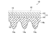
- FIG. 2 is a cross-sectional view of a V-ribbed belt.
- FIG. 3 is a view showing a list of rubber compounds used in the verification test.
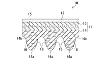
- FIG. 4 is a view corresponding to FIG. 2 in the case where the DLC film is formed only on the side surface of the rib portion.
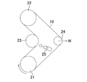
- FIG. 5 is a view showing a layout of a belt traveling test.
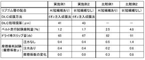
- FIG. 6 is a diagram showing a list of verification results.
- FIG. 7 is a graph showing temporal changes in friction coefficient and sound pressure in the case of (a) Comparative Example 1 and (b) Example 1; FIG.
- FIG. 8 is a graph showing the time change of the friction coefficient and the sound pressure in the case of (a) Comparative Example 2 and (b) in Example 2;
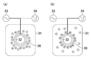
- FIG. 9 is a view showing a schematic configuration of a film forming apparatus used for the ion implantation film forming method.
- FIG. 10 is a schematic view showing each state of (a) plasma generation and (b) ion implantation of the film forming apparatus used for the ion implantation film forming method.
- FIG. 11 is a perspective view showing a part of a toothed belt according to a second embodiment.
- FIG. 12 is a view corresponding to FIG. 11 in the case where a DLC film is formed only at the root portion of a belt tooth.
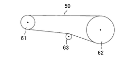
- FIG. 13 is a diagram showing a layout of a belt traveling test.
- FIG. 14 is a diagram showing a list of verification results in the case where a DLC film is formed on the belt side.
- FIG. 15 is a diagram showing a list of verification results when
- Embodiment 1 -Constitution- A belt transmission according to a first embodiment of the present invention is shown in FIG.
- This belt transmission includes V-ribbed pulleys 1 and 2 as a driving pulley and a driven pulley, and each pulley 1 and 2 is formed with a plurality of ribs extending in the belt length direction on the inner peripheral surface.
- a V-ribbed belt 10 as a transmission belt is wound around.
- the drive pulley 1 is mounted on the drive shaft 5 so as to be integral with the drive shaft 5 and is configured to rotate counterclockwise in FIG. 1 by the drive shaft 5.
- the driven pulley 2 is attached to the input shaft 6 so as to be integral with the input shaft 6 and configured to transmit the driving force transmitted from the drive pulley 1 via the V-ribbed belt 10 to the input shaft 6.
- the drive pulley 1 and the driven pulley 2 are each formed with a plurality of grooves (not shown) extending in the circumferential direction on the outer peripheral surface, and formed on the inner peripheral side of the V-ribbed belt 10 on the groove surfaces.
- the side surfaces of the plurality of rib portions 14a (ribs) are in contact with each other.
- the V-ribbed belt 10 includes a belt main body 11 and a back surface canvas layer 12 laminated on the upper surface (back surface, outer peripheral surface) side of the belt main body 11, and the belt main body 11 is
- the adhesive rubber layer 13 has a substantially rectangular shape in cross section, and a rib rubber layer 14 laminated on the lower surface side of the adhesive rubber layer 13, that is, the lower surface (bottom surface, inner peripheral surface) side of the belt main body 11.
- the back surface canvas layer 12 is adhered to the back surface of the belt main body 11 (adhesive rubber layer 13) after being subjected to adhesion processing with a rubber paste in which rubber is dissolved in a solvent in a woven fabric such as nylon or cotton. Thereby, the back surface canvas layer 12 bears one end of power transmission in the case where the belt back surface is wound so as to abut on a flat pulley (for example, back surface idler or the like).
- a flat pulley for example, back surface idler or the like.
- the adhesive rubber layer 13 is made of a rubber composition such as ethylene propylene diene monomer (EPDM) excellent in heat resistance and weather resistance, and in the adhesive rubber layer 13, it extends in the belt length direction and has a belt width.
- a core wire 15 which is spirally wound so as to line up at a predetermined pitch in the direction is embedded.
- the core wire 15 is formed by twisting a plurality of single yarns made of polyester (PET) fibers or the like.
- the rib rubber layer 14 is made of a rubber composition containing EPDM as a main rubber, as shown in FIG. 3 described later, in the same manner as the adhesive rubber layer 13. Then, on the lower surface side of the rib rubber layer 14, a plurality of rib portions 14a, 14a, ... (three strips in this embodiment) extending in the belt length direction are formed to be aligned at a predetermined pitch in the belt width direction ing.
- the side surfaces of the rib portions 14 a of the rib rubber layer 14 abut the side surfaces of the grooves of the V-ribbed pulleys 1 and 2.
- short fibers 14b, 14b, ... are contained in the rib rubber layer 14 including the above-mentioned rib portions 14a in a state of being oriented in the belt width direction (FIG. 2) reference).
- the short fibers 14b, 14b,... are made of, for example, nylon fibers, aramid fibers or the like, and when the respective rib portions 14a are formed by grinding, the side surfaces (surfaces of the respective rib portions 14a) It protrudes outward from).
- composition of the ribbed rubber layer 14 of the V-ribbed belt 10 is shown in FIG.
- two types were prepared: one containing short fibers (rubber blend A in FIG. 3) and one not containing short fibers (rubber blend B in FIG. 3).
- the composition of each component when EPDM is 100 phr is as shown in the above-mentioned FIG.
- EPDM is EP24 made by JSR
- anti-aging agent is Nocrac MB made by Ouchi Shinko Chemical Co., Ltd.
- Co-crosslinking agent is Hicross M made by SEIKO CHEMICAL CO., LTD.
- the 2280 and short fibers used 1 mm cut fiber of nylon fiber, respectively.
- the DLC film 16 As a method of forming the DLC film 16, for example, film forming methods such as sputtering, CVD (chemical vapor deposition), PVD (physical vapor deposition), and ion implantation film forming can be considered. In order to form a DLC film on the surface, the film was formed by an ion implantation film forming method that can obtain high adhesion without losing flexibility.
- the above ion implantation film forming method is a film forming method called a so-called plasma based ion implantation film forming method (PBII / D method: Plasma Based Ion Implantation / Deposition), and has a structure as shown in FIG.
- PBII / D method Plasma Based Ion Implantation / Deposition
- This is a method of forming a DLC film uniformly on the surface of the substrate 36 by accelerating cations ionized in the plasma using the film device 30 and implanting them into the substrate 36.
- the film forming apparatus 30 includes a vacuum chamber 31, an electrode 32 disposed in the vacuum chamber 31, a plasma generation high frequency power supply 33 for applying a high frequency voltage to the electrode 32, and the electrode A high voltage pulse generating power supply 34 for applying a negative high voltage pulse voltage to the electrode 32; a superimposing device 35 for superimposing the outputs of the plasma generating high frequency power supply 33 and the high voltage pulse generating power supply 34; And.
- the vacuum chamber 31 is provided with an inlet 31a for introducing a gas such as methane or toluene (see the white arrow in the figure).
- the electrode 32 is formed in a ring shape as an example, but not limited to this, it may have any shape.
- the substrate 36 is disposed on the surface of the electrode 32.
- a gas such as methane or toluene is introduced into the vacuum chamber 31 via the inlet 31a, as shown in FIG. 10A
- the high frequency voltage from the high frequency power source 33 for plasma generation to the electrode 32 To generate plasma in the vacuum chamber 31 to ionize the gas.
- a high voltage pulse voltage of negative polarity is applied to the electrode 32 from the high voltage pulse generation power source 34, and a substrate placed on the surface of the electrode 32.
- the cations in the vacuum chamber 31 are accelerated and implanted.
- the film forming conditions for forming the DLC film are the high frequency voltage applied to the electrode 32 corresponding to 300 W at 500 Hz, and the pulse applied to the electrode 32 The voltage is 5 kV.
- the film formation time is 3 hours.
- the DLC film 16 may be formed on the entire surface of the rib portion 14a as shown in FIG. 2 or the side surface of the rib portion 14a abutting on the grooves of the pulleys 1 and 2 as shown in FIG. It may be formed only on the top. As described above, by forming the DLC film 16 only on the side surface of the rib portion 14a, it is possible to obtain characteristics as described later when the DLC film is formed without losing the flexibility or the like of the rib portion 14a. It becomes possible. As described above, as a method of forming the DLC film 16 only on the side surface of the rib portion 14a, for example, a method using a pattern can be considered.
- FIG. 5 shows the layout of the V-ribbed belt 10 and the pulleys 21, 22, 23, 24 in the belt running test. Specifically, the V-ribbed belt 10 is wound around the driving pulley 21 and the driven pulley 22 having a diameter of 120 mm, and the idler pulley 23 having a diameter of 70 mm and the idler pulley 24 having a diameter of 55 mm Approximately 90 degrees, it is arranged to change.
- the respective pulleys 21, 22, 23, 24 are set such that the load acting on the driven pulley 22 is 2.5 kgW per rib, and the idler pulley 24 has 277 N per rib Set the set weight W to be In this state, the drive pulley 21 was rotated at 4900 rpm.
- the running test as described above is performed at room temperature (25 ⁇ 2 ° C.) for 24 hours, and the weight loss after the running test is measured, and the weight loss when the initial weight before the running test is 100% is worn away Evaluate as a quantity.
- the results are shown in FIG.
- the wear amount can be reduced to half or less compared to 1, 2).
- the amount of wear can be reduced to about one third by forming the DLC film 16.
- the slip noise of the V-ribbed belt 10 was also measured during the belt running test.
- the microphone 25 of a sound level meter (manufactured by RION, model name "NA-40") is installed at a position about 10 cm from the position where the belt 10 contacts the idler pulley 23 and the belt is run The noise was measured.
- FIG. 6 when the DLC film 16 is not formed on the surface of the rib portion 14a by using the ion implantation film forming method, the DLC film 16 is not formed (Comparative Examples 1 and 2).
- the slip noise can be significantly reduced.
- the rib rubber layer 14 does not contain the short fiber 14 b (Example 2, Comparative Example 2)
- the slip noise can be significantly reduced from 91 dB to 67 dB by forming the DLC film 16. .
- Friction test Next, a friction measurement test was conducted using a pin-on-disk type testing apparatus.
- the rubber test pieces rib rubber layers of the above-described Examples 1 and 2 and Comparative Examples 1 and 2 held so that the tip end portion protrudes in the holder are surface pressure against the FC material which is the opposite material.
- the contact is made to be 0.8 MPa, and the mating material is rotated so that the sliding speed becomes 0.11 m / s.
- FIG. 7 shows the results of (a) Comparative Example 1 and (b) Example 1
- FIG. 8 shows the results of (a) Comparative Example 2 and (b) Example 2.
- the friction coefficient is 0.2 or more, friction can be transmitted between the transmission belt and the pulley, so as shown in FIG. 6, the rubber material constituting the rib rubber layer is If the coefficient of friction when the DLC film 16 is formed on the surface is 0.4, good transmission characteristics can be obtained.
- the DLC film 16 is formed on the contact surface of the rib portion 14 a of the V-ribbed belt 10 with the pulleys 1 and 2 using the ion implantation film forming method, so the DLC film is formed.
- the amount of wear, the coefficient of friction, and the noise can be reduced as compared to the case where there is no such.
- the DLC film is not formed by forming the DLC film 16 by using the ion implantation film formation method in a case where the short fiber 14b is not contained in the rib rubber layer 14 (Comparative Example 2), and the short fiber
- the amount of wear, the coefficient of friction and the noise can be reduced more than in the case where the rib 14 b is contained in the rib rubber layer 14 (Comparative Example 1), so that the short fibers 14 b can be omitted. Accordingly, since it is not necessary to manufacture the V-ribbed belt 10 in a state in which the short fibers 14b are oriented in the ribbed rubber layer 14, the manufacturing cost of the V-ribbed belt 10 can be reduced.
- Embodiment 2 a second embodiment of the present invention will be described based on FIG. 11 to FIG.
- the DLC film 56 is formed on the contact surface of the toothed belt 50 in which the belt teeth 51 are provided side by side in the belt length direction.
- the toothed belt 50 includes a tooth rubber 52 forming belt teeth 51 provided on the belt inner circumferential surface side with a predetermined pitch in the belt length direction, and a belt rear surface portion And a core 54 extending in the belt length direction and forming a pitch in the belt width direction to provide a spiral, and a tooth cloth 55 covering the inner circumferential surface of the belt. .
- the tooth rubber 52 is made of a rubber composition containing hydrogenated nitrile rubber (HNBR) excellent in oil resistance as a main rubber, and has a substantially trapezoidal cross section and is formed over the entire belt width.
- the rubber composition of the tooth rubber 52 is as shown in the rubber composition C of FIG.
- the details of each compounding component are the same as in the case of the first embodiment, but HNBR used Zetpol 2020 manufactured by Nippon Zeon Co., Ltd., and Oil 1 used Adekasizer RS 107 manufactured by Asahi Denka Kogyo Co., Ltd.
- For the core wire 54 a glass cord having a high elastic modulus is used.
- the tooth cloth 55 is made of nylon.
- the belt teeth 51 mesh with the teeth (not shown) formed on the outer peripheral surface of the pulley, and the side surfaces of the belt teeth 51 and the teeth of the pulley It comes in contact with the side of the part.
- the tooth cloth 55 is impregnated with a rubber paste obtained by dissolving an aqueous resorcin / formalin latex (RFL) solution and a rubber composition in a solvent. More specifically, a nylon tooth cloth 55 is impregnated with the RFL aqueous solution and dried, then impregnated with a low concentration rubber paste, dried, and then coated with a high concentration rubber paste.
- RFL aqueous resorcin / formalin latex
- Example 3 and Comparative Example 3 those without the tooth cloth 55 are referred to as Example 3 and Comparative Example 3, and those into which the tooth cloth 55 is impregnated with only the RFL aqueous solution are referred to as Example 4 and Comparative Example 4, respectively.
- the tooth cloth 55 impregnated with an RFL aqueous solution and a rubber paste is referred to as Examples 5 to 8 and Comparative Example 5.
- the DLC film 56 was formed on the contact surface of the belt teeth 51 with the pulley (see FIG. 11). As shown in FIG. 14, the DLC film 56 is formed by using the above-described ion implantation film forming method as Examples 3 to 5, and formed by using a known PVD method as Example 6. Example 7 was formed by using a known CVD method. Further, those in which the DLC film was not formed were taken as Comparative Examples 3 to 5, respectively.
- a DLC film is formed by the ion implantation film forming method only on the portion of the pulley in contact with the toothed belt 50 separately from the above Examples 3 to 7 and Comparative Examples 3 to 5.
- Example 8 was prepared. That is, in the eighth embodiment, the DLC film is not formed on the side of the toothed belt 50.
- the film forming conditions of the ion implantation film forming method are the same as those of the first and second embodiments of the first embodiment.
- carbon is sputter-deposited for about 2 hours to form a DLC film
- 900 W of high frequency equivalent to 900 W under an environment of a pressure of 0.5 Pa into which a gas of toluene is introduced. A voltage was applied to form a film.
- the DLC film 56 may be formed on the entire surface of the belt teeth 51 as shown in FIG. 11 or, as shown in FIG.
- the DLC film 56 may be formed only at the root portion of the large belt teeth 51.
- the belt tooth 51 is not in contact with the tooth portion of the pulley as described in detail without losing the flexibility of the belt tooth 51 and the like. It is possible to improve the wear resistance at the time.
- a method of forming the DLC film 51 only on the root portion of the belt tooth 51 for example, a method using a pattern can be considered.
- FIG. 13 shows a layout of the toothed belt 50 and the pulleys 61, 62, 63 at the time of the belt traveling test.
- a drive pulley 61 having 21 pulley grooves (not shown) provided on the outer peripheral surface of the pulley and having a toothed portion, and 42 pulley grooves provided on the outer peripheral surface of the pulley
- the toothed belt 50 is wound around a driven pulley 62 having a toothed portion and an idler pulley 63 having a diameter of 32 mm for pressing the back surface of the belt so that a tension of 216 N acts on the toothed belt 50.
- the above-mentioned driven pulley 62 is loaded. Then, the drive pulley 61 was rotated at 6000 rpm in a state where a load of 60 N ⁇ m was applied to the driven pulley 62.
- the traveling test as described above is carried out at an atmosphere temperature of 100 ° C., and the traveling time until the loss of the belt teeth 51 of the toothed belt 50 occurs is the same as that of Comparative Example 5 (with tooth cloth and RFL aqueous solution and rubber paste).
- the case of being impregnated was determined as a standard (the result of Comparative Example 5 is assumed to be 100).
- the results are shown in FIG.
- FIG. 14 by forming the DLC film 56 on the belt teeth 51 of the toothed belt 50, it is possible to improve the tooth skipping durability. In particular, even in the case without the tooth cloth (comparative example 3), the durability can be dramatically improved by forming the DLC film 56 on the belt teeth 51 as in the example 3.
- the tooth skipping durability is improved because the DLC film 56 has high hardness and the friction coefficient of the surface of the belt tooth 51 can be reduced. This is because the wear on the root portion of the belt tooth 51 due to the above can be reduced.
- the examples in which the DLC film 56 is formed by using the ion implantation film forming method the examples in which the DLC film is formed by using the PVD method or the CVD method.
- the film thickness (treated film thickness) of the DLC film is larger than those of 6, 7 and it is understood that the ion implantation film forming method is suitable for forming a thicker DLC film.
- higher tooth skipping durability can be obtained as compared with the above-described sixth and seventh embodiments. Therefore, in order to improve the tooth skipping durability of the toothed belt 50, it is considered that the formation of the DLC film by the ion implantation film forming method is more preferable.
- FIG. 15 shows the results of determining the tooth skipping durability of the toothed belt 50 by carrying out the above-mentioned running test on Example 8 in which the DLC film was formed only on the pulley side.
- Example 8 Even when the DLC film is formed only on the pulley side (Example 8), it is higher than Comparative Example 5 in which the DLC film is not formed on any of the toothed belt and the pulley. Tooth fly durability is obtained.
- the DLC film is formed on the belt teeth 51 and pulleys of the toothed belt 50.
- the coefficient of friction between the toothed belt 50 and the pulley can be reduced, and it is considered that the slip noise can also be reduced.
- Embodiment 2- since the DLC film 56 is formed on the contact surface of the toothed belt 50 with the pulleys of the belt teeth 51, the tooth flight durability of the toothed belt 50 can be improved. That is, even if the tooth cloth 55 of the belt tooth 51 is not impregnated with the RFL aqueous solution or rubber paste, the tooth cloth 55 is impregnated with the RFL aqueous solution or rubber paste by forming the DLC film 56 as described above. Tooth skipping durability higher than that in the case where a film is not formed (Comparative Example 5) can be obtained.
- the film thickness can be increased as compared with other PVD methods and CVD methods, and the tooth jumping durability of the toothed belt 50 can be further enhanced. It can be improved.
- the configuration of the present invention is not limited to the above embodiments, but includes various other configurations. That is, although the configuration in which the belt transmission includes the two pulleys 1 and 2 is shown in the first embodiment, the present invention is not limited to this, and three or more pulleys may be provided. May be provided.
- the DLC films 16 and 56 are formed on the V-ribbed belt 10 and the toothed belt 50, respectively.
- the present invention is not limited to this. May be formed.
- the DLC film is formed on either the contact surface of the belt with the pulley or the contact surface of the pulley with the belt, but the present invention is not limited to this.
- a DLC film may be formed on the contact surface.
- a DLC film having a film thickness as shown in FIG. 6, FIG. 14, and FIG. 15 is formed on the surface of the belt or pulley. Any film thickness may be used as long as such a characteristic is obtained. Specifically, in consideration of the durability of the DLC film and the obtained characteristics, the film thickness of the DLC film is preferably 0.5 to 100 ⁇ m, more preferably 3 to 80 ⁇ m.
- the belt transmission according to the present invention can reduce the amount of abrasion, the coefficient of friction, and the noise of the belt by the DLC film, and thus is particularly useful for a mechanism that transmits power using the belt.
Landscapes
- Engineering & Computer Science (AREA)
- General Engineering & Computer Science (AREA)
- Mechanical Engineering (AREA)
Abstract
少なくとも2つのプーリに伝動ベルトが巻き掛けられたベルト伝動装置において、騒音を低減しつつ摩耗特性も改善することができる構成を簡単且つ低コストな構成で実現する。ベルト伝動装置を構成するプーリ及び伝動ベルトの少なくとも一方の接触面上に、DLC膜を形成する。
Description
本発明は、少なくとも2つのプーリ間に伝動ベルトが巻き掛けられたベルト伝動装置、及びそれに用いる伝動ベルトに関する。
従来より、エンジンやモータなどの駆動力を被駆動側に伝える構成として、駆動側及び被駆動側の回転軸にプーリを連結し、これらのプーリに伝動ベルトを巻き掛ける構成が広く知られている。このように、伝動ベルトを用いた構成では、該伝動ベルトに平ベルトやVベルト、Vリブドベルトなどを用いて、伝動ベルトとプーリとの接触時の摩擦によって動力を伝達するものや、伝動ベルトに歯付ベルトなどを用いて、伝動ベルトとプーリとの歯の噛み合わせによって動力を伝達するものなどがある。いずれの構成の場合でも、伝動ベルトとプーリとの接触によって駆動力を伝達するため、両者の接触状態によって伝動特性等が大きく影響を受けることになる。
特に、近年、自動車では低騒音・低振動などの高い快適性が求められており、エンジンまわりの振動や騒音も極力小さくすることが要求されている。これに伴い、エンジンまわりに用いられているベルト伝動装置でも、運転時の騒音抑制が求められており、騒音抑制のために種々の構成が考えられている。伝動ベルトの騒音を抑制する方法としては、例えば伝動ベルトがプーリと接触する実質的な接触面積を低減する方法が知られている。具体的には、例えば特許文献1に示すように、Vリブドベルトにおいて、リブの側面から外方に向かって突出するように短繊維が配向された状態で含まれるゴム組成物によりリブゴム層を構成し、該ゴム組成物の表面を研削するなどしてその表面から短繊維を突出させることで、接触面積の低減を図り、騒音の抑制を行うものが知られている。
一方、上記歯付ベルトを用いたベルト伝動装置の場合には、騒音以外にも、該歯付ベルトのベルト歯がプーリの歯部との接触によって摩耗するという問題が生じる。すなわち、上記歯付ベルトのベルト歯に対してプーリの歯部が噛合すると、該ベルト歯の付け根に大きな力が作用し、該付け根部分で摩耗が生じ、最終的には亀裂等が発生する。これに対し、例えば特許文献2に開示されるように、歯付ベルトのゴム層の接触面側を歯布によって覆うとともに、該歯布に対してレゾルシン・ホルマリン・ラテックス(RFL)水溶液及びゴム組成物を溶剤に溶解させてなるゴム糊などを含浸させる接着処理を行って、該歯布の強度を高めることで、上述のような摩耗や亀裂の発生を抑えるようにしている。
特開2005-126642号公報
特開2003-343658号公報
ところで、上述のように、騒音低減のためにリブ側面から短繊維が突出するように配向した状態でリブゴム層を形成する方法や、歯付ベルトのベルト歯を構成するゴム層を覆う歯布にRFL水溶液やゴム糊などを含浸させる方法は、多くの処理工程が必要になるため、製造工程が複雑になるうえ、製造コストが高くなるという問題が生じる。
本発明は、斯かる点に鑑みてなされたものであり、その目的とするところは、少なくとも2つのプーリ間に伝動ベルトが巻き掛けられたベルト伝動装置において、騒音を低減しつつ摩耗特性も改善することができる構成を簡単且つ低コストな構成で実現することにある。
上記目的を達成するために、本発明に係るベルト伝動装置では、プーリ及び伝動ベルトの少なくとも一方の接触面上にDLC膜を形成するようにしたため、リブゴム層内で短繊維を所定の方向に配向させたり、ゴム層を覆う歯布にRFL水溶液及びゴム糊を含浸させたりするなどの工程を行うことなく、低摩擦で騒音が小さく且つ低摩耗の接触状態を得ることができる。
すなわち、本発明は、互いに平行な回転軸上に設けられた少なくとも2つのプーリと、それらのプーリ間に巻き掛けられた伝動ベルトとを備えたベルト伝動装置を対象とする。そして、上記プーリ及び伝動ベルトの接触面のうち少なくとも一方の接触面上にDLC膜が形成されているものとする。
この構成により、プーリと伝動ベルトとの接触部分に、高硬度で低摩擦のDLC膜が形成され、このDLC膜によって、上記プーリと伝動ベルトとの間の摩擦係数を低減して騒音を低減できるとともに、摩耗量も低減することができる。
具体的には、図6に示すように、短繊維の配合されていない伝動ベルトであっても、接触面にDLC膜を形成することで、短繊維が配合されている従来の構成よりも摩擦係数を低下させてスリップ音を低減することができるとともに、摩耗量も低減することができる。しかも、上記DLC膜を接触面上に形成することで、注水時の摩擦係数の変動をほとんど無くすことができ、注水時のスリップ音の増大も防止することができる。
また、図14に示すように、ゴム層を覆う歯布の表面上にDLC膜を形成することで、該歯布にRFL水溶液やゴム糊を含浸させなくても、歯布にRFL水溶液及びゴム糊を含浸させる従来の構成よりも摩耗に対する耐久性を向上することができる。
上述の構成において、上記伝動ベルトは、内周面上にベルト長さ方向に延びる複数のリブが形成されたVリブドベルトであり、上記リブの側面上に上記DLC膜が形成されているものとする(第2の発明)。
このように上記伝動ベルトがVリブドベルトの場合には、該Vリブドベルトがプーリと接触する部分の面、すなわちリブの側面上にDLC膜を形成することで、Vリブドベルトとプーリとの接触部分の摩擦係数及び摩耗量を低減することができる。すなわち、リブの表面全体にDLC膜を形成しなくても、該リブの側面にDLC膜を形成することで、摩耗量や摩擦係数、騒音を低減することができるので、上記リブの柔軟性を大きく失うことなく、DLC膜によって摩擦・摩耗特性を改善することが可能となる。
また、上記DLC膜は、イオン注入成膜法によって形成されたものであるのが好ましい(第3の発明)。これにより、PVD法やCVD法などの他の成膜方法に比べて、DLC膜の膜厚を大きくすることができるとともに、伝動ベルトの耐久性を高めることができる。
第4の発明は、伝動ベルトに関するものであり、具体的には、互いに平行な回転軸上に設けられた少なくとも2つのプーリ間に巻き掛けられる伝動ベルトを対象としていて、上記プーリとの接触面上にDLC膜が形成されているものとする。これにより、上記第1の発明と同様の作用を奏する伝動ベルトを得ることができる。
上記第4の発明の構成においても、上記DLC膜は、イオン注入成膜法によって形成されたものであるのが好ましい(第5の発明)。これにより、PVD法やCVD法などの他の成膜方法に比べて、DLC膜の膜厚を大きくすることができるとともに、伝動ベルトの耐久性を高めることができる。
以上より、本発明に係るベルト伝動装置によれば、プーリ及び伝動ベルトの接触面のうち少なくとも一方の接触面上にDLC膜を形成したので、該DLC膜によってプーリと伝動ベルトとの摩擦係数を低減してスリップ音を低減することができるとともに、摩耗量も低減することができる。特に、上記伝動ベルトがVリブドベルトの場合には、リブゴム層内に所定の方向に配向するように短繊維を配合しなくても、上記DLC膜をリブ側面に設けることで、リブの柔軟性を失うことなく接触面の低摩擦・低摩耗を実現できるとともに、製造工程の簡略化及び製造コストの低減を図れる。しかも、上記DLC膜をイオン注入成膜法によって形成することで、伝動ベルトの耐久性をより向上させることができる。
1 駆動プーリ
2 従動プーリ
5 駆動軸(回転軸)
6 入力軸(回転軸)
10 Vリブドベルト
11 ベルト本体
14 リブゴム層
14a リブ部
14b 短繊維
16 DLC膜
50 歯付ベルト
51 ベルト歯
52 歯ゴム
55 歯布
56 DLC膜
2 従動プーリ
5 駆動軸(回転軸)
6 入力軸(回転軸)
10 Vリブドベルト
11 ベルト本体
14 リブゴム層
14a リブ部
14b 短繊維
16 DLC膜
50 歯付ベルト
51 ベルト歯
52 歯ゴム
55 歯布
56 DLC膜
以下、本発明の実施形態を図面に基づいて説明する。なお、以下の好ましい実施形態の説明は、本質的に例示に過ぎず、本発明、その適用物或いはその用途を制限することを意図するものではない。
《実施形態1》
-構成-
本発明の実施形態1に係るベルト伝動装置を図1に示す。このベルト伝動装置は、駆動プーリ及び従動プーリとしてのVリブドプーリ1,2を備えていて、該各プーリ1,2には、内周面上にベルト長さ方向に延びる複数のリブが形成された伝動ベルトとしてのVリブドベルト10が巻き掛けられている。
-構成-
本発明の実施形態1に係るベルト伝動装置を図1に示す。このベルト伝動装置は、駆動プーリ及び従動プーリとしてのVリブドプーリ1,2を備えていて、該各プーリ1,2には、内周面上にベルト長さ方向に延びる複数のリブが形成された伝動ベルトとしてのVリブドベルト10が巻き掛けられている。
上記駆動プーリ1は、駆動軸5に回転一体に取り付けられていて、その駆動軸5によって図1において反時計回りに回転するように構成されている。一方、上記従動プーリ2は、入力軸6に回転一体に取り付けられていて、前記駆動プーリ1からVリブドベルト10を介して伝達される駆動力を入力軸6に伝達するように構成されている。
また、上記駆動プーリ1及び従動プーリ2には、それぞれ、外周面上に周方向に延びる複数の溝(図示省略)が形成されていて、該溝面に上記Vリブドベルト10の内周側に形成された複数のリブ部14a(リブ)の側面が当接するようになっている。
上記Vリブドベルト10は、図2に示すように、ベルト本体11と、このベルト本体11の上面(背面、外周面)側に積層された背面帆布層12とを備えており、前記ベルト本体11は、横断面で見て略矩形状の接着ゴム層13と、該接着ゴム層13の下面側、すなわちベルト本体11の下面(底面、内周面)側に積層されたリブゴム層14とからなる。
上記背面帆布層12は、ナイロンや綿等の織布にゴムを溶剤に溶かしたゴム糊による接着処理が施されてベルト本体11(接着ゴム層13)の背面に貼付されている。これにより、上記背面帆布層12は、ベルト背面がフラットなプーリ(例えば、背面アイドラなど)に当接するように巻き掛けられた場合の動力伝達の一端を担っている。
一方、上記接着ゴム層13は、耐熱性及び耐候性に優れたエチレンプロピレンジエンモノマー(EPDM)等のゴム組成物からなり、該接着ゴム層13内には、ベルト長さ方向に延び且つベルト幅方向に所定ピッチをあけて並ぶように螺旋状に巻かれた心線15が埋設されている。なお、この心線15は、ポリエステル(PET)繊維等からなる複数の単糸を撚り合わせることによって構成されている。
上記リブゴム層14は、後述する図3に示すように、上記接着ゴム層13と同様、主体ゴムとしてEPDMを含むゴム組成物からなる。そして、このリブゴム層14の下面側には、それぞれベルト長さ方向に延びる複数条のリブ部14a,14a,…(本実施形態では3条)がベルト幅方向に所定ピッチで並ぶように形成されている。これにより、Vリブドベルト10をVリブドプーリ1,2に巻き掛けた場合には、前記リブゴム層14の各リブ部14aの側面が該Vリブドプーリ1,2の溝の側面に当接する。
また、後述する実施例1及び比較例1では、上記各リブ部14aを含むリブゴム層14には、短繊維14b,14b,…がベルト幅方向に配向された状態で含有されている(図2参照)。この短繊維14b,14b,…は、例えば、ナイロン繊維やアラミド繊維等によって構成されたもので、前記各リブ部14aが研削加工によって形成される場合には、該各リブ部14aの側面(表面)から外方に突出した状態となる。
〈リブゴム層の配合〉
図3に、Vリブドベルト10のリブゴム層14の配合を示す。本実施形態では、短繊維を含有しているもの(図3においてゴム配合A)と、短繊維を含有していないもの(図3においてゴム配合B)の2種類を用意した。EPDMを100phrとした場合の各成分の配合は上記図3に示すとおりである。なお、EPDMはJSR社製のEP24を、老化防止剤は大内新興化学社製のノクラックMBを、共架橋剤は精工化学社製のハイクロスMを、オイル2は日本サン石油社製のサンパー2280を、短繊維はナイロン繊維の1mmカットファイバーを、それぞれ用いた。
図3に、Vリブドベルト10のリブゴム層14の配合を示す。本実施形態では、短繊維を含有しているもの(図3においてゴム配合A)と、短繊維を含有していないもの(図3においてゴム配合B)の2種類を用意した。EPDMを100phrとした場合の各成分の配合は上記図3に示すとおりである。なお、EPDMはJSR社製のEP24を、老化防止剤は大内新興化学社製のノクラックMBを、共架橋剤は精工化学社製のハイクロスMを、オイル2は日本サン石油社製のサンパー2280を、短繊維はナイロン繊維の1mmカットファイバーを、それぞれ用いた。
〈DLC処理〉
上述のような構成で且つ上記図3に示すリブゴム層14の配合からなる2種類(ゴム配合A:短繊維あり、ゴム配合B:短繊維なし)のVリブドベルト10に対し、それぞれのリブ部14aの表面上にダイヤモンド・ライク・カーボン(DLC)膜16を形成した。その一例として、ゴム配合AのものにDLC膜16を形成した場合を上記図2に示す。ゴム配合A、Bのリブゴム層14に上記DLC膜16を形成したものをそれぞれ実施例1、2とし、DLC膜16が形成されていないものをそれぞれ比較例1、2とした。なお、本実施形態で形成したDLC膜16の膜厚は、図6に示すように、実施例1で略41μm、実施例2で略43μmである。
上述のような構成で且つ上記図3に示すリブゴム層14の配合からなる2種類(ゴム配合A:短繊維あり、ゴム配合B:短繊維なし)のVリブドベルト10に対し、それぞれのリブ部14aの表面上にダイヤモンド・ライク・カーボン(DLC)膜16を形成した。その一例として、ゴム配合AのものにDLC膜16を形成した場合を上記図2に示す。ゴム配合A、Bのリブゴム層14に上記DLC膜16を形成したものをそれぞれ実施例1、2とし、DLC膜16が形成されていないものをそれぞれ比較例1、2とした。なお、本実施形態で形成したDLC膜16の膜厚は、図6に示すように、実施例1で略41μm、実施例2で略43μmである。
上記DLC膜16を形成する方法としては、例えば、スパッタや、CVD(化学蒸着法)、PVD(物理蒸着法)、イオン注入成膜法などの各成膜方法が考えられるが、ここでは、ベルト表面にDLC膜を形成するため、柔軟性を損なうことなく高い密着性の得られるイオン注入成膜法によって成膜した。
ここで、上記イオン注入成膜法は、いわゆるプラズマベースイオン注入成膜方式(PBII/D方式:Plasma Based Ion Implantation/Deposition)と呼ばれる成膜方法であり、図9に示すような構成を有する成膜装置30を用いて、プラズマ中で電離している陽イオンを加速させて基材36に打ち込むことにより該基材36の表面に均一にDLC膜を成膜する方法である。
詳しくは、上記成膜装置30は、真空チャンバー31と、該真空チャンバー31内に配置される電極32と、該電極32に高周波の電圧を印加するためのプラズマ発生用高周波電源33と、上記電極32に負極性の高電圧のパルス電圧を印加するための高電圧パルス発生用電源34と、該プラズマ発生用高周波電源33及び高電圧パルス発生用電源34の出力を重畳するための重畳装置35と、を備えている。また、上記真空チャンバー31には、メタンやトルエンなどのガスを導入する(図中の白抜き矢印参照)ための導入口31aが設けられている。なお、上記図9では、上記電極32は、一例としてリング状に形成されているが、この限りではなく、どのような形状であってもよい。
上述のような構成を有する成膜装置30を用いた成膜方法について、図10に基づいて以下で説明する。まず、上記電極32の表面上に基材36を配置する。そして、真空チャンバー31内にメタンやトルエンなどのガスが導入口31aを介して導入された後、図10(a)に示すように、上記プラズマ発生用高周波電源33から上記電極32に高周波の電圧を印加して、該真空チャンバー31内でプラズマを発生させ、上記ガスをイオン化させる。次に、図10(b)に示すように、上記高電圧パルス発生用電源34から上記電極32に負極性の高電圧のパルス電圧を印加して、該電極32の表面に配置された基材に対し上記真空チャンバー31内の陽イオンを加速させて打ち込む。このように、プラズマ生成と陽イオンの打ち込みとを同一の電極32を用いて行うことにより、基材36に近い位置でイオン化させて該基材36の表面に均一に打ち込むことができる。したがって、上記イオン注入成膜法では、単に原料ガスをプラズマ化させて蒸着させるCVD法で成膜する場合よりも基材36に対するDLC膜の密着性を向上させることができるとともに、スパッタしたカーボンを基材に対して打ち込むPVD法よりも柔軟性を有するDLC膜を形成することができる。しかも、上述のような成膜装置30を用いることで、3次元で成膜することも可能になるとともに、比較的、低温で成膜することができる。
ここで、上記図6の実施例1、2において、DLC膜を成膜する際の成膜条件は、電極32に印加する高周波の電圧が500Hzで300W相当であり、該電極32に印加するパルス電圧が5kVである。また、成膜時間は3時間である。
なお、上記DLC膜16は、上記図2に示すようにリブ部14aの表面全体に形成してもよいし、図4に示すように、プーリ1,2の溝に当接するリブ部14aの側面上にのみ形成してもよい。このように、上記リブ部14aの側面上にのみ上記DLC膜16を形成することで、該リブ部14aの柔軟性等を失うことなく、DLC膜を形成した場合の後述するような特性を得ることが可能となる。なお、上述のように、リブ部14aの側面上にのみDLC膜16を形成する方法としては、例えば、パターンを用いた方法などが考えられる。
-検証結果-
〈ベルト走行試験〉
以上のような構成のVリブドベルト10を用いてベルト走行試験を行い、摩耗量や摩擦係数、スリップ音を計測した。図5にベルト走行試験時のVリブドベルト10及び各プーリ21,22,23,24のレイアウトを示す。具体的には、直径120mmの駆動プーリ21及び従動プーリ22にVリブドベルト10が巻き掛けられているとともに、直径70mmのアイドラプーリ23及び直径55mmのアイドラプーリ24がともに上記Vリブドベルト10の進行方向を略90度、変更するように配置されている。そして、上記各プーリ21,22,23,24は、上記従動プーリ22に作用する負荷がリブ一山あたり2.5kgWとなるようにセットされ、上記アイドラプーリ24には、リブ1山あたり277NとなるようにセットウェイトWをセットする。この状態で、上記駆動プーリ21を4900rpmで回転させた。
〈ベルト走行試験〉
以上のような構成のVリブドベルト10を用いてベルト走行試験を行い、摩耗量や摩擦係数、スリップ音を計測した。図5にベルト走行試験時のVリブドベルト10及び各プーリ21,22,23,24のレイアウトを示す。具体的には、直径120mmの駆動プーリ21及び従動プーリ22にVリブドベルト10が巻き掛けられているとともに、直径70mmのアイドラプーリ23及び直径55mmのアイドラプーリ24がともに上記Vリブドベルト10の進行方向を略90度、変更するように配置されている。そして、上記各プーリ21,22,23,24は、上記従動プーリ22に作用する負荷がリブ一山あたり2.5kgWとなるようにセットされ、上記アイドラプーリ24には、リブ1山あたり277NとなるようにセットウェイトWをセットする。この状態で、上記駆動プーリ21を4900rpmで回転させた。
上述のような走行試験を、室温(25±2℃)で24時間実施し、走行試験後の重量減少を測定して、走行試験前の初期重量を100%としたときの重量減少分を摩耗量として評価する。この結果を図6に示す。この図6の実施例1、2に示すように、リブ部14aの表面にイオン注入成膜法を用いてDLC膜16を形成することで、該DLC膜16を形成していない場合(比較例1,2)に比べて、摩耗量を半分以下にすることができる。特に、リブゴム層14に短繊維14bが含有されていない場合(実施例2、比較例2)には、DLC膜16を形成することで摩耗量を約3分の1まで減らすことができる。
また、上記図5に示すように、ベルト走行試験時にVリブドベルト10のスリップ音も測定した。具体的には、上記アイドラプーリ23にベルト10が接する位置から側方約10cmの位置に、騒音計(RION社製、型名「NA-40」)のマイクロホン25を設置し、ベルト走行時の騒音を測定した。この結果も上記図6に示す。この図6に示すように、上記リブ部14aの表面にイオン注入成膜法を用いてDLC膜16を形成することで、該DLC膜16を形成していない場合(比較例1、2)に比べて、スリップ音を大幅に低減することができる。特に、リブゴム層14に短繊維14bが含有されていない場合(実施例2、比較例2)には、DLC膜16を形成することで、スリップ音を91dBから67dBまで大幅に低減することができる。
〈摩擦試験〉
次に、ピンオンディスク型の試験装置を用いて摩擦測定試験を行った。特に図示しないが、ホルダに先端部分が突出するように保持されたゴム試験片(上記実施例1,2及び比較例1,2のリブゴム層)を、相手材であるFC材に対して面圧0.8MPaとなるように当接させるとともに、該相手材を摺動速度が0.11m/sになるように回転させる。ここで、上記FC材の表面は、プーリの接触面と同程度の表面粗度(Ra=0.3μm)を有している。
次に、ピンオンディスク型の試験装置を用いて摩擦測定試験を行った。特に図示しないが、ホルダに先端部分が突出するように保持されたゴム試験片(上記実施例1,2及び比較例1,2のリブゴム層)を、相手材であるFC材に対して面圧0.8MPaとなるように当接させるとともに、該相手材を摺動速度が0.11m/sになるように回転させる。ここで、上記FC材の表面は、プーリの接触面と同程度の表面粗度(Ra=0.3μm)を有している。
上述のような試験を室温(25±2℃)下で行い、開始3分後に水20μLを注水して、注水なし(注水前)の場合と注水あり(注水後)の場合とで摩擦係数を求めた。この結果を上記図6中に数値で示すとともに、図7及び図8に注水前後の摩擦係数及び音圧の変化を示す。ここで、図7は(a)比較例1、(b)実施例1の結果をそれぞれ示し、図8は(a)比較例2、(b)実施例2の結果をそれぞれ示す。
これらの結果から分かるように、注水なしの場合、イオン注入成膜法を用いてDLC膜16を形成した方(実施例1、2)が、DLC膜16を形成していないもの(比較例1、2)に比べて、摩擦係数が低くなるとともに、イオン注入成膜法を用いてDLC膜16を形成しているものは、注水を行っても摩擦係数はほとんど変動せず、安定している。そのため、摩擦に起因して発生する騒音も、注水のない場合には、DLC膜16を形成しているもの(実施例1、2)の方が、該DLC膜16を形成していないもの(比較例1、2)に比べて小さく、注水後のスリップ音もDLC膜16を形成しているものの方が小さい。
なお、一般的に、摩擦係数が0.2以上であれば、伝動ベルトとプーリとの間で摩擦伝動を行うことができるため、上記図6に示すように、リブゴム層を構成するゴム材料の表面にDLC膜16を形成した場合の摩擦係数が0.4であれば、良好な伝動特性を得ることができる。
-実施形態1の効果-
以上より、この実施形態によれば、Vリブドベルト10のリブ部14aのプーリ1,2との接触面上に、イオン注入成膜法を用いてDLC膜16を形成したため、DLC膜を形成していない場合に比べて摩耗量や摩擦係数、騒音を低減することができる。特に、リブゴム層14内に短繊維14bが含有されていないもの(比較例2)にイオン注入成膜法を用いてDLC膜16を形成することで、DLC膜が形成されておらず且つ短繊維14bがリブゴム層14内に含有されているもの(比較例1)よりも摩耗量、摩擦係数及び騒音を低減することができるため、該短繊維14bを省略することが可能になる。したがって、リブゴム層14内に短繊維14bを配向させた状態でVリブドベルト10を製作する必要がなくなるので、該Vリブドベルト10の製造コストの低減を図れる。
以上より、この実施形態によれば、Vリブドベルト10のリブ部14aのプーリ1,2との接触面上に、イオン注入成膜法を用いてDLC膜16を形成したため、DLC膜を形成していない場合に比べて摩耗量や摩擦係数、騒音を低減することができる。特に、リブゴム層14内に短繊維14bが含有されていないもの(比較例2)にイオン注入成膜法を用いてDLC膜16を形成することで、DLC膜が形成されておらず且つ短繊維14bがリブゴム層14内に含有されているもの(比較例1)よりも摩耗量、摩擦係数及び騒音を低減することができるため、該短繊維14bを省略することが可能になる。したがって、リブゴム層14内に短繊維14bを配向させた状態でVリブドベルト10を製作する必要がなくなるので、該Vリブドベルト10の製造コストの低減を図れる。
《実施形態2》
次に、本発明の第2実施形態を図11から図15に基づいて説明する。この実施形態では、ベルト歯51がベルト長さ方向に並んで設けられている歯付ベルト50の接触面上にDLC膜56を形成する。
次に、本発明の第2実施形態を図11から図15に基づいて説明する。この実施形態では、ベルト歯51がベルト長さ方向に並んで設けられている歯付ベルト50の接触面上にDLC膜56を形成する。
-構成-
具体的には、図11に示すように、歯付ベルト50は、ベルト長さ方向に所定ピッチでベルト内周面側に突設されたベルト歯51を形成する歯ゴム52と、ベルト背面部を構成する背ゴム53と、ベルト長さ方向に延び且つベルト幅方向にピッチを形成して螺旋状に設けられた心線54と、ベルト内周面を被覆する歯布55とを備えている。
具体的には、図11に示すように、歯付ベルト50は、ベルト長さ方向に所定ピッチでベルト内周面側に突設されたベルト歯51を形成する歯ゴム52と、ベルト背面部を構成する背ゴム53と、ベルト長さ方向に延び且つベルト幅方向にピッチを形成して螺旋状に設けられた心線54と、ベルト内周面を被覆する歯布55とを備えている。
上記歯ゴム52は、主体ゴムとして耐油性に優れた水素化ニトリルゴム(HNBR)を含むゴム組成物からなり、断面が略台形状でベルト幅全体に亘って形成されている。この歯ゴム52のゴム配合は、上記図3のゴム配合Cに示すとおりである。なお、各配合成分の詳細については、上記実施形態1の場合と同様であるが、HNBRは日本ゼオン社製のZetpol2020を、オイル1は旭電化工業社製のアデカサイザーRS107をそれぞれ用いた。上記心線54には、高弾性率を有するガラスコードが用いられている。また、上記歯布55はナイロン製である。
これにより、上記歯付ベルト50は、プーリに巻き掛けられると、ベルト歯51がプーリの外周面に形成された歯部(図示省略)に噛合して、該ベルト歯51の側面とプーリの歯部の側面とが当接するようになっている。
〈接着処理〉
上記歯布55には、レゾルシン・ホルマリン・ラテックス(RFL)水溶液及びゴム組成物を溶剤に溶解させてなるゴム糊が含浸されている。より詳しくは、ナイロン製の歯布55に対し、上記RFL水溶液を含浸させて乾燥させた後、低濃度のゴム糊を含浸させて乾燥させ、さらにその後、高濃度のゴム糊でコーティングする。
上記歯布55には、レゾルシン・ホルマリン・ラテックス(RFL)水溶液及びゴム組成物を溶剤に溶解させてなるゴム糊が含浸されている。より詳しくは、ナイロン製の歯布55に対し、上記RFL水溶液を含浸させて乾燥させた後、低濃度のゴム糊を含浸させて乾燥させ、さらにその後、高濃度のゴム糊でコーティングする。
本実施形態では、それぞれ、上記歯布55のないものを実施例3及び比較例3とし、上記歯布55に対してRFL水溶液のみを含浸させたものを実施例4及び比較例4とし、上記歯布55に対してRFL水溶液及びゴム糊を含浸させたものを実施例5~8及び比較例5とする。
〈DLC処理〉
上述のような各構成の歯付ベルト50に対し、ベルト歯51のプーリとの接触面上にDLC膜56を形成した(図11参照)。図14に示すように、このDLC膜56を、上述のイオン注入成膜法を用いて形成したものをそれぞれ実施例3~5とし、公知のPVD法を用いて形成したものを実施例6とし、公知のCVD法を用いて形成したものを実施例7とした。また、DLC膜が形成されていないものをそれぞれ比較例3~5とした。
上述のような各構成の歯付ベルト50に対し、ベルト歯51のプーリとの接触面上にDLC膜56を形成した(図11参照)。図14に示すように、このDLC膜56を、上述のイオン注入成膜法を用いて形成したものをそれぞれ実施例3~5とし、公知のPVD法を用いて形成したものを実施例6とし、公知のCVD法を用いて形成したものを実施例7とした。また、DLC膜が形成されていないものをそれぞれ比較例3~5とした。
一方、図15に示すように、上記実施例3~7及び比較例3~5とは別に、プーリの歯付ベルト50と接触する部分にのみ、DLC膜をイオン注入成膜法によって形成した実施例8を用意した。すなわち、この実施例8では、歯付ベルト50側にDLC膜は形成されていない。
なお、本実施形態において、上記イオン注入成膜法の成膜条件は、上記実施形態1の実施例1、2の場合と同様である。また、上記PVD法では、カーボンのスパッタ蒸着を約2時間、行ってDLC膜を成膜し、上記CVD法では、トルエンのガスが導入された圧力0.5Paの環境下で900W相当の高周波の電圧を印加して成膜した。
ここで、上記DLC膜56は、上記図11に示すようにベルト歯51の表面全体に形成してもよいし、図12に示すように、プーリの歯部に当接し且つ発生する応力が最も大きいベルト歯51の付け根部分にのみ、DLC膜56を形成してもよい。このように、上記ベルト歯51の付け根部分にのみ上記DLC膜56を形成することで、該ベルト歯51の柔軟性等を失うことなく、詳しくは後述するように、プーリの歯部との接触時の耐摩耗性を向上することができる。なお、上述のように、ベルト歯51の付け根部分にのみDLC膜51を形成する方法としては、例えば、パターンを用いた方法などが考えられる。
-検証結果-
〈高負荷歯飛び耐久試験〉
上述のような構成を有する歯付ベルト50を用いてベルト走行試験を行い、高負荷での歯飛び耐久性の評価を行った。図13にベルト走行試験時の歯付ベルト50、各プーリ61,62,63のレイアウトを示す。具体的には、プーリの外周面上に21箇所のプーリ溝(図示省略)が設けられて歯部が構成された駆動プーリ61と、プーリの外周面上に42箇所のプーリ溝が設けられて歯部が構成された従動プーリ62と、ベルト背面を押圧するための直径32mmのアイドラプーリ63とに、上記歯付ベルト50を巻き掛けて、該歯付ベルト50に216Nの張力が作用するように上記従動プーリ62に荷重をかけた。そして、上記従動プーリ62に60N・mの負荷をかけた状態で上記駆動プーリ61を6000rpmで回転させた。
〈高負荷歯飛び耐久試験〉
上述のような構成を有する歯付ベルト50を用いてベルト走行試験を行い、高負荷での歯飛び耐久性の評価を行った。図13にベルト走行試験時の歯付ベルト50、各プーリ61,62,63のレイアウトを示す。具体的には、プーリの外周面上に21箇所のプーリ溝(図示省略)が設けられて歯部が構成された駆動プーリ61と、プーリの外周面上に42箇所のプーリ溝が設けられて歯部が構成された従動プーリ62と、ベルト背面を押圧するための直径32mmのアイドラプーリ63とに、上記歯付ベルト50を巻き掛けて、該歯付ベルト50に216Nの張力が作用するように上記従動プーリ62に荷重をかけた。そして、上記従動プーリ62に60N・mの負荷をかけた状態で上記駆動プーリ61を6000rpmで回転させた。
上述のような走行試験を雰囲気温度100度で行い、上記歯付ベルト50のベルト歯51の欠損が発生するまでの走行時間を、上記比較例5(歯布ありで且つRFL水溶液及びゴム糊に含浸させている場合)の場合を基準(比較例5の結果を100とする)として求めた。その結果を図14に示す。この図14から分かるように、上記歯付ベルト50のベルト歯51上にDLC膜56を形成することで、歯飛び耐久性を向上することができる。特に、歯布のないもの(比較例3)でも、実施例3のようにベルト歯51上にDLC膜56を形成することによって、耐久性を飛躍的に向上することができる。すなわち、歯布のないものは、歯布があって且つRFL水溶液及びゴム糊を含浸させたもの(比較例5)に比べてかなり低い耐久性しかないのに、上記DLC膜56を形成することで、歯布がないものでも、上記比較例5よりも高い耐久性を実現することができる。
このように、上記DLC膜56を形成することにより、歯飛び耐久性が向上するのは、DLC膜56が高硬度であり且つベルト歯51の表面の摩擦係数を低減できるため、プーリの歯部による該ベルト歯51の付け根部分に対する摩耗を低減できるからである。
また、上記図14に示すように、イオン注入成膜法を用いてDLC膜56が形成された実施例3~5の方が、PVD法やCVD法を用いてDLC膜が形成された実施例6、7に比べて、DLC膜の膜厚(処理膜厚)が大きくなっており、より厚いDLC膜を形成するのにイオン注入成膜法が適していることが分かる。しかも、イオン注入成膜法でDLC膜56が形成された上記実施例5では、上記実施例6、7に比べて高い歯飛び耐久性が得られることが分かる。したがって、歯付ベルト50の歯飛び耐久性を向上させるためには、イオン注入成膜法によるDLC膜の形成がより好ましいと考えられる。
さらに、上述のような効果は、歯付ベルト50側にDLC膜56を形成した場合だけでなく、プーリ側にDLC膜を形成した場合でも得ることができる。図15に、プーリ側にのみDLC膜を形成した実施例8について、上述の走行試験を行って歯付ベルト50の歯飛び耐久性を求めた結果を示す。この図15から分かるように、プーリ側にのみDLC膜を形成した場合(実施例8)でも、歯付ベルト及びプーリのいずれにもDLC膜が形成されていない上記比較例5に比べて、高い歯飛び耐久性が得られる。
なお、上記図14及び図15には特に試験結果等を示していないが、上述のように、歯付ベルト50のベルト歯51やプーリにDLC膜を形成することで、上記実施形態1の場合と同様、歯付ベルト50とプーリとの摩擦係数を低減することができ、スリップ音も低減することができると考えられる。
-実施形態2の効果-
以上より、この実施形態によれば、歯付ベルト50のベルト歯51のプーリとの接触面上にDLC膜56を形成したため、該歯付ベルト50の歯飛び耐久性を向上することができる。すなわち、上記ベルト歯51の歯布55にRFL水溶液やゴム糊を含浸させなくても、上述のようにDLC膜56を形成することで、歯布55にRFL水溶液やゴム糊が含浸され且つDLC膜が形成されていないもの(比較例5)よりも高い歯飛び耐久性を得ることができる。
以上より、この実施形態によれば、歯付ベルト50のベルト歯51のプーリとの接触面上にDLC膜56を形成したため、該歯付ベルト50の歯飛び耐久性を向上することができる。すなわち、上記ベルト歯51の歯布55にRFL水溶液やゴム糊を含浸させなくても、上述のようにDLC膜56を形成することで、歯布55にRFL水溶液やゴム糊が含浸され且つDLC膜が形成されていないもの(比較例5)よりも高い歯飛び耐久性を得ることができる。
しかも、上記DLC膜56をイオン注入成膜法によって形成することで、他のPVD法やCVD法に比べて、膜厚を大きくすることができ、上記歯付ベルト50の歯飛び耐久性をさらに向上させることができる。
また、上記歯付ベルト50ではなく、プーリ側のベルト接触面にDLC膜を形成することによっても、該歯付ベルト50の歯飛び耐久性の向上を図ることができる。
《その他の実施形態》
本発明の構成は、上記各実施形態に限定されるものではなく、それ以外の種々の構成を包含するものである。すなわち、実施形態1には、ベルト伝動装置が2つのプーリ1,2を備えている構成が示されているが、この限りではなく、3個以上のプーリを備えていてもよいし、アイドラプーリを備えていてもよい。
本発明の構成は、上記各実施形態に限定されるものではなく、それ以外の種々の構成を包含するものである。すなわち、実施形態1には、ベルト伝動装置が2つのプーリ1,2を備えている構成が示されているが、この限りではなく、3個以上のプーリを備えていてもよいし、アイドラプーリを備えていてもよい。
また、上記各実施形態では、それぞれ、Vリブドベルト10及び歯付ベルト50にDLC膜16,56を形成した場合について説明したが、この限りではなく、平ベルトやVベルトの接触面上にDLC膜を形成してもよい。
また、上記各実施形態では、ベルトのプーリとの接触面上またはプーリのベルトとの接触面上のいずれか一方にDLC膜を形成しているが、この限りではなく、ベルト及びプーリの両方の接触面上にDLC膜を形成してもよい。
また、上記各実施形態では、ベルトまたはプーリの表面に、図6、図14及び図15にそれぞれ示すような膜厚のDLC膜を形成しているが、この限りではなく、上記各実施形態のような特性が得られる膜厚であれば、どのような膜厚であってもよい。具体的には、DLC膜の耐久性や得られる特性を考慮すると、DLC膜の膜厚は、0.5~100μmが好ましく、より好ましくは3~80μmである。
以上説明したように、本発明におけるベルト伝動装置は、DLC膜によって、ベルトの摩耗量及び摩擦係数、騒音の低減を図れるので、ベルトを用いて動力を伝達する機構に特に有用である。
Claims (5)
- 互いに平行な回転軸上に設けられた少なくとも2つのプーリと、それらのプーリ間に巻き掛けられた伝動ベルトとを備えたベルト伝動装置であって、
上記プーリ及び伝動ベルトの接触面のうち少なくとも一方の接触面上にDLC膜が形成されていることを特徴とするベルト伝動装置。 - 請求項1において、
上記伝動ベルトは、内周面上にベルト長さ方向に延びる複数のリブが形成されたVリブドベルトであり、
上記リブの側面上に上記DLC膜が形成されていることを特徴とするベルト伝動装置。 - 請求項1または2において、
上記DLC膜は、イオン注入成膜法によって形成されたものであることを特徴とするベルト伝動装置。 - 互いに平行な回転軸上に設けられた少なくとも2つのプーリ間に巻き掛けられる伝動ベルトであって、
上記プーリとの接触面上にDLC膜が形成されていることを特徴とする伝動ベルト。 - 請求項4において、
上記DLC膜は、イオン注入成膜法によって形成されたものであることを特徴とする伝動ベルト。
Applications Claiming Priority (2)
| Application Number | Priority Date | Filing Date | Title |
|---|---|---|---|
| JP2007340453 | 2007-12-28 | ||
| JP2007-340453 | 2007-12-28 |
Publications (1)
| Publication Number | Publication Date |
|---|---|
| WO2009084231A1 true WO2009084231A1 (ja) | 2009-07-09 |
Family
ID=40823967
Family Applications (1)
| Application Number | Title | Priority Date | Filing Date |
|---|---|---|---|
| PCT/JP2008/004023 Ceased WO2009084231A1 (ja) | 2007-12-28 | 2008-12-26 | ベルト伝動装置及びそれに用いる伝動ベルト |
Country Status (1)
| Country | Link |
|---|---|
| WO (1) | WO2009084231A1 (ja) |
Cited By (1)
| Publication number | Priority date | Publication date | Assignee | Title |
|---|---|---|---|---|
| JP2014521890A (ja) * | 2011-03-16 | 2014-08-28 | ザ ゲイツ コーポレイション | ベルト式遊星伝達装置 |
Citations (6)
| Publication number | Priority date | Publication date | Assignee | Title |
|---|---|---|---|---|
| JPH10184811A (ja) * | 1996-12-24 | 1998-07-14 | Bando Chem Ind Ltd | Vリブドベルト |
| JP2001336584A (ja) * | 2000-05-31 | 2001-12-07 | Mitsuboshi Belting Ltd | Vリブドベルト |
| JP2003232408A (ja) * | 2002-02-07 | 2003-08-22 | Koyo Seiko Co Ltd | Vベルト |
| JP2004084894A (ja) * | 2002-08-29 | 2004-03-18 | Mitsuboshi Belting Ltd | Vリブドベルト |
| JP2004125102A (ja) * | 2002-10-04 | 2004-04-22 | Nsk Ltd | 樹脂製プーリ |
| JP2007071319A (ja) * | 2005-09-08 | 2007-03-22 | Nsk Ltd | プーリ付転がり軸受 |
-
2008
- 2008-12-26 WO PCT/JP2008/004023 patent/WO2009084231A1/ja not_active Ceased
Patent Citations (6)
| Publication number | Priority date | Publication date | Assignee | Title |
|---|---|---|---|---|
| JPH10184811A (ja) * | 1996-12-24 | 1998-07-14 | Bando Chem Ind Ltd | Vリブドベルト |
| JP2001336584A (ja) * | 2000-05-31 | 2001-12-07 | Mitsuboshi Belting Ltd | Vリブドベルト |
| JP2003232408A (ja) * | 2002-02-07 | 2003-08-22 | Koyo Seiko Co Ltd | Vベルト |
| JP2004084894A (ja) * | 2002-08-29 | 2004-03-18 | Mitsuboshi Belting Ltd | Vリブドベルト |
| JP2004125102A (ja) * | 2002-10-04 | 2004-04-22 | Nsk Ltd | 樹脂製プーリ |
| JP2007071319A (ja) * | 2005-09-08 | 2007-03-22 | Nsk Ltd | プーリ付転がり軸受 |
Cited By (1)
| Publication number | Priority date | Publication date | Assignee | Title |
|---|---|---|---|---|
| JP2014521890A (ja) * | 2011-03-16 | 2014-08-28 | ザ ゲイツ コーポレイション | ベルト式遊星伝達装置 |
Similar Documents
| Publication | Publication Date | Title |
|---|---|---|
| CN100346102C (zh) | 低增长传动带 | |
| TWI361255B (en) | Toothed power transmission belt | |
| CN1128945C (zh) | 耐磨皮带及其制造方法 | |
| KR100668406B1 (ko) | 전동 벨트 및 방법 | |
| CN101384834B (zh) | 齿形带和调速控制系统 | |
| KR101614573B1 (ko) | 톱니형 벨트 및 오일 중 톱니형 벨트의 용도 | |
| US20030027920A1 (en) | Rubber composition, a method of making the rubber composition, a power transmission belt made from rubber composition and a method of making the power transmission belt | |
| JP6588368B2 (ja) | 歯付ベルト | |
| JP6748133B2 (ja) | 摩擦伝動ベルト及びその製造方法 | |
| EP0624738A1 (en) | Canvas-rubber complex, V-ribbed belt using it and method of producing V-ribbed belt | |
| WO2006057129A1 (ja) | Vリブドベルト及びそれを用いた自動車の補機駆動用ベルト伝動装置 | |
| KR20090100378A (ko) | 마찰 전동 벨트 | |
| WO2009110150A1 (ja) | Vリブドベルト | |
| CN111656047A (zh) | 齿形带 | |
| JPWO2007110974A1 (ja) | 伝動ベルト | |
| WO2009084231A1 (ja) | ベルト伝動装置及びそれに用いる伝動ベルト | |
| JP6748152B2 (ja) | Vリブドベルト | |
| CN101855471A (zh) | 用于齿形带的耐久层和该齿形带 | |
| EP3971331B1 (en) | Twisted cord for core wire of transmission belt, manufacturing method and use of same, and transmission belt | |
| CN113574222A (zh) | 传动带用芯线的处理剂、以及芯线和其制造方法 | |
| WO2007036959A1 (en) | Belt drive for use in oil provided with a shoe | |
| CN118043570A (zh) | 用于油的齿形动力传送带 | |
| EP3650731B1 (en) | V-ribbed belt | |
| JP2006316812A (ja) | 伝動ベルト | |
| JP2004108576A (ja) | 歯付ベルト |
Legal Events
| Date | Code | Title | Description |
|---|---|---|---|
| 121 | Ep: the epo has been informed by wipo that ep was designated in this application |
Ref document number: 08869224 Country of ref document: EP Kind code of ref document: A1 |
|
| NENP | Non-entry into the national phase |
Ref country code: DE |
|
| 122 | Ep: pct application non-entry in european phase |
Ref document number: 08869224 Country of ref document: EP Kind code of ref document: A1 |
|
| NENP | Non-entry into the national phase |
Ref country code: JP |