WO2009084179A1 - ビットパターンドメディアを用いた磁気記録装置 - Google Patents
ビットパターンドメディアを用いた磁気記録装置 Download PDFInfo
- Publication number
- WO2009084179A1 WO2009084179A1 PCT/JP2008/003878 JP2008003878W WO2009084179A1 WO 2009084179 A1 WO2009084179 A1 WO 2009084179A1 JP 2008003878 W JP2008003878 W JP 2008003878W WO 2009084179 A1 WO2009084179 A1 WO 2009084179A1
- Authority
- WO
- WIPO (PCT)
- Prior art keywords
- bit
- magnetic
- magnetic recording
- bit carrier
- magnetic head
- Prior art date
- Legal status (The legal status is an assumption and is not a legal conclusion. Google has not performed a legal analysis and makes no representation as to the accuracy of the status listed.)
- Ceased
Links
Images

Classifications
-
- G—PHYSICS
- G11—INFORMATION STORAGE
- G11B—INFORMATION STORAGE BASED ON RELATIVE MOVEMENT BETWEEN RECORD CARRIER AND TRANSDUCER
- G11B5/00—Recording by magnetisation or demagnetisation of a record carrier; Reproducing by magnetic means; Record carriers therefor
- G11B5/74—Record carriers characterised by the form, e.g. sheet shaped to wrap around a drum
- G11B5/82—Disk carriers
-
- B—PERFORMING OPERATIONS; TRANSPORTING
- B82—NANOTECHNOLOGY
- B82Y—SPECIFIC USES OR APPLICATIONS OF NANOSTRUCTURES; MEASUREMENT OR ANALYSIS OF NANOSTRUCTURES; MANUFACTURE OR TREATMENT OF NANOSTRUCTURES
- B82Y10/00—Nanotechnology for information processing, storage or transmission, e.g. quantum computing or single electron logic
-
- G—PHYSICS
- G11—INFORMATION STORAGE
- G11B—INFORMATION STORAGE BASED ON RELATIVE MOVEMENT BETWEEN RECORD CARRIER AND TRANSDUCER
- G11B5/00—Recording by magnetisation or demagnetisation of a record carrier; Reproducing by magnetic means; Record carriers therefor
- G11B5/74—Record carriers characterised by the form, e.g. sheet shaped to wrap around a drum
- G11B5/743—Patterned record carriers, wherein the magnetic recording layer is patterned into magnetic isolated data islands, e.g. discrete tracks
Definitions
- the present invention relates to a magnetic recording apparatus using a bit patterned medium, and more particularly to a magnetic recording apparatus that controls recording / reproducing timing of a magnetic head in synchronization with a bit carrier.
- a magnetic recording medium having a ferromagnetic polycrystalline thin film This is also called a granular type, in which a ferromagnetic polycrystalline thin film composed of a plurality of magnetic particles having high uniaxial magnetic anisotropy is provided on a medium, and magnetic particles are contained in one bit of recorded information. It is included in multiple numbers. As the recording density increases, the number of magnetic particles contained in one bit decreases, so that the magnetic flux decreases and noise increases. Until now, we have been increasing the density by reducing the size of the magnetic particles, but if the particle size is made smaller than this, the energy to hold the magnetic information will be insufficient, and even for thermal energy at room temperature. Information will be lost.
- a magnetic recording device using a discrete track medium As another method for increasing the density, a magnetic recording device using a discrete track medium has been proposed. As the density increases, the influence of side track recording on adjacent tracks and the influence of crosstalk due to the magnetic field generated from the side surface of the magnetic head become a problem. Discrete track media has been considered to suppress or reduce these effects. In discrete track media, the magnetic recording layers are separated by grooves. That is, since there are grooves between the tracks and they are magnetically and physically separated, there is no magnetization disturbance between the tracks, and the influence of side track recording or the like can be suppressed.
- a bit patterned medium in which a magnetic recording layer is separated in the track longitudinal direction and one magnetic particle is recorded as one bit.
- This is a structure in which a magnetic layer is physically separated for each magnetic particle, and a magnetic material is evenly arranged as a bit carrier in the track longitudinal direction.
- Patent Document 1 discloses a light-assisted magnetic recording apparatus that irradiates a predetermined position with a light spot from a light source and controls focusing and tracking using reflected light.
- Patent Document 1 discloses that a magnetic recording medium having a configuration in which land-and-groove irregularities are formed in the direction intersecting with the longitudinal direction of the recording track (discrete track medium) can be used. In this case, it is also possible to obtain a tracking servo signal for applying a magnetic field of the magnetic head by detecting reflected light.
- Patent Document 2 discloses a technique for compensating for the rotation unevenness of the spindle motor of a magnetic recording medium in a magnetic recording apparatus using a bit patterned medium.
- a clock information track for generating a clock signal is circumferentially provided on a magnetic recording medium, and this is used as a trigger for recording / reproduction.
- the recording / reproducing timing and the bit carrier can be synchronized.
- the technique disclosed in Patent Document 2 is a technique for compensating for the rotation unevenness of the magnetic recording medium, and is a technique on the premise that no positional deviation occurs with respect to the arrangement position of the bit carrier. Further, a clock information track is separately provided in order to detect rotation unevenness, but it is assumed that there is no positional deviation in the clock information track itself. Therefore, even if phase compensation due to rotation unevenness can be performed, synchronization cannot be achieved if there is a deviation in the arrangement of the bit carriers.
- the present invention intends to provide a magnetic recording apparatus capable of controlling the recording / reproducing timing of a magnetic head with respect to a bit carrier of a bit patterned medium.
- a magnetic recording apparatus using a bit patterned medium includes a bit patterned medium in which a plurality of bit carriers made of a magnetic material are arranged on a magnetic recording medium, and a bit A magnetic head for recording / reproducing information on / from the carrier, a detecting unit for detecting the arrangement position of the bit carrier and outputting a correlation signal before recording / reproducing the bit carrier by the magnetic head, and a detecting unit And a timing control unit for controlling the timing of recording / reproducing with respect to the bit carrier of the magnetic head using the correlation signal output by.
- the detection unit may be any device that detects a physical phenomenon change caused by the arrangement position of the bit carrier.
- the detection unit may be any device that detects a physical phenomenon change caused by at least one of a light intensity change, a capacitance change, a magnetic change, an eddy current change, and a sound wave reflection time change with respect to the bit carrier.
- the detection unit may include a plasmon antenna.
- the detection unit may detect a change in electric field strength of the antenna rear end line of the plasmon antenna.
- the timing controller may use a correlation signal as a clock signal for recording / reproducing of the magnetic head.
- a tracking control unit for controlling the position of the magnetic head with respect to the radial direction of the magnetic recording medium may be provided.
- the detection unit may detect a physical phenomenon change while vibrating the detection unit in the direction of the radiation of the magnetic recording medium.
- the magnetic recording apparatus of the present invention has an advantage that the recording / reproducing timing of the magnetic head can be controlled in synchronization with the bit carrier even if the bit carrier of the bit patterned medium is misaligned.
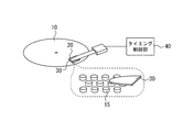
- FIG. 1 is a schematic perspective view for explaining the configuration of a magnetic recording apparatus using the bit patterned medium of the present invention.
- FIG. 2 is a simulation result of a change in electric field strength distribution with respect to the positional relationship between the plasmon antenna and the bit carrier.
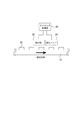
- FIG. 3 is a schematic cross-sectional view of the bit patterned medium and a conceptual diagram showing the positional relationship between the magnetic head and the detection unit.
- bit patterned media 15 bit carrier 20 magnetic head 30 detector 31 plasmon antenna 40 timing controller
- FIG. 1 is a schematic perspective view for explaining the configuration of a magnetic recording apparatus using the bit patterned medium of the present invention.
- the magnetic recording apparatus of the present invention is mainly composed of a bit patterned medium 10, a magnetic head 20, a detection unit 30, and a timing control unit 40.
- bit patterned medium 10 used as a magnetic recording medium a plurality of bit carriers (recording carriers) 15 made of a magnetic material are arranged on the magnetic recording medium.
- the bit carrier 15 is formed so that one bit corresponds to one bit carrier, for example, by a semiconductor manufacturing process or the like. For example, as shown in a partially enlarged view of FIG. Thus, it is separated into a magnetic region serving as a bit carrier and a nonmagnetic region serving as the other region.
- the bit-patterned medium is not limited to those formed with physical irregularities, and any structure can be used as long as it is a medium configured to be a 1-bit 1-bit carrier. It may be.
- a medium that is magnetically separated by changing the composition or the film structure may be used.
- the magnetic head 20 records and reproduces information with respect to the bit carrier 15.
- the magnetic head 20 may be either a horizontal magnetic recording system or a perpendicular magnetic recording system, and any conventional or future magnetic head to be developed is applicable.
- the detecting unit 30 detects the arrangement position of the bit carrier 15 before recording / reproducing on the bit carrier 15 by the magnetic head 20. That is, the detection unit 30 is for detecting in advance the arrangement position of the bit carrier 15 to be recorded / reproduced by the magnetic head 20 before performing the recording / reproduction.
- the bit carrier 15 is manufactured by a high-precision process. However, as the arrangement pitch of the bit carrier 15 becomes finer, for example, 25 nm pitch in order to increase the recording density, the deviation of the arrangement position of the bit carrier 15 due to a manufacturing error. The impact can no longer be ignored.
- the detection unit 30 is provided to detect the arrangement position of the bit carrier in order to compensate for this deviation, detects the arrangement position of the bit carrier, and outputs a correlation signal corresponding to the arrangement position based on the detection position. To do.
- Various methods can be used for detecting the bit carrier arrangement position.
- a change in a physical phenomenon due to the arrangement position of a bit carrier examples include a light intensity change, a capacitance change, a magnetic change, an eddy current change, and a sound wave reflection time change with respect to the bit carrier 15.
- the near-field light intensity changes depending on the arrangement position of the bit carrier 15, and this is detected.
- the capacitance the fact that the capacitance between the metal plates changes depending on the arrangement position of the bit carrier 15 is utilized.
- the change in hardness can be detected by detecting the change in magnetism with a magnetic sensor, detecting the change in eddy current generated in the metal plate, or measuring the time when the reflected wave returns by irradiating ultrasonic waves. By detecting it, it is possible to detect the arrangement position of the bit carrier.
- a plasmon antenna can be used for the detection unit 30.
- the plasmon antenna uses surface plasmons induced on a metal surface and can form a light microspot.
- the electrodes of the plasmon antenna have various shapes such as a bow tie type and a triangular type.
- a strong local light spot can be formed using the resonance effect of surface plasmons by utilizing the fact that a local magnetic field is generated in the central portion when a uniform alternating magnetic field is applied to the electrodes.
- FIG. 2 shows a simulation result of a change in the electric field strength distribution with respect to the positional relationship between the plasmon antenna and the bit carrier. The analysis conditions in the simulation are as follows.
- the plasmon antenna 31 an antenna made of Pt having an antenna length of 400 mn was used. Further, the bit carrier 15 is a 30 nm spherical material arranged at a 45 nm pitch. In the simulation, Pt is used as the bit carrier, but a magnetic material such as a Co—Cr alloy may be used.
- a light source for the plasmon antenna 31 a circularly polarized light source with a linearly polarized Gaussian distribution having an electric field of 1 V / m in the x direction in the figure was used. Under such conditions, the electric field intensity distribution at the position of the outermost surface (tip) of the antenna was simulated.
- the bit carrier side moves in the ⁇ x direction as the magnetic recording medium rotates.
- a peak is observed in the electric field intensity distribution when the tip of the antenna is directly above the bit carrier. Therefore, by detecting this peak for each bit carrier, that is, by detecting a physical phenomenon caused by the bit carrier placement position, more specifically, the bit carrier placement position, more specifically, the track longitudinal direction of the bit carrier. Variation in pitch can be detected. And the detection part 30 should just output the change of this arrangement position as a correlation signal.
- the near-field light intensity of a plasmon antenna changes under the influence of an overlapping bit carrier. As shown in Table 1, since the near-field light intensity obtained differs between the end of the antenna rear end line of the plasmon antenna and the center of the antenna rear end line, these two electric field intensity values are used in combination. Thus, a physical phenomenon caused by the arrangement position of the bit carrier may be detected.
- the timing control unit 40 controls the recording / reproducing timing with respect to the bit carrier 15 of the magnetic head 20. That is, the position of the bit carrier 15 is detected, and the magnetic head 20 is recorded / reproduced in accordance with the timing of the arrangement.
- the timing control unit 40 may be configured to output a clock signal that determines the recording / reproducing timing of the magnetic head 20, and a correlation signal corresponding to a change in the arrangement position of the bit carrier is used as the clock signal.
- the arrangement position of the bit carrier can be detected and used as it is as a clock signal.
- the timing control unit outputs a clock signal delayed by a predetermined timing according to the relationship between the rotation speed of the magnetic recording medium and the distance between the magnetic head and the detection unit, and the magnetic head performs recording / reproduction based on the clock signal. Just do it.
- FIG. 3 is a schematic cross-sectional view of the bit patterned medium and a conceptual diagram showing the positional relationship between the magnetic head and the detection unit.
- a detection unit 30 is disposed prior to the magnetic head 20 with respect to the bit carrier 15, and the preceding bit carrier 15 to be recorded / reproduced by the detection unit 30 in advance before recording / reproduction by the magnetic head 20. It is comprised so that the arrangement position of may be detected. That is, after detecting the arrangement position of a bit carrier preceding several bits to several tens of bits, recording / reproduction is performed when the bit carrier comes directly under the magnetic head 20 in synchronization with the arrangement position of the bit carrier.
- the recording / reproducing timing can be phase-synchronized with the bit carrier only by controlling the clock signal for determining the recording / reproducing timing of the magnetic head 20, that is, only by signal control. Therefore, the time lag is less likely to be a problem compared to mechanically controlling the magnetic head.
- the bit carrier of the bit patterned medium is directly detected, and the detected signal is used as a recording / reproducing clock signal. Even if a misalignment occurs, the phase of the bit carrier can be compensated, so that recording and generation can be performed in synchronization with the misalignment, and the bit error rate can be greatly improved. Become.
- the magnetic recording apparatus of the present invention not only the bit carrier misalignment compensation but also the rotation unevenness compensation is simultaneously performed. In other words, even if there is rotation unevenness, this is also detected as a positional deviation of the bit carrier, and therefore it is not affected by the rotation unevenness. It should be noted that the fluctuation between the time delay until the actual recording / reproduction after the detection of the arrangement position of the preceding bit carrier can be ignored in practice. This is because the magnetic recording medium rotates at a rotational speed of about 10,000 revolutions per minute, and due to the moment of inertia of the magnetic recording medium, the rotation unevenness has a fluctuation period on the order of several hertz. Therefore, if the arrangement position of the bit carrier preceding several bits to several tens of bits is detected, it is possible to sufficiently cope with the rotation unevenness as described above.
- the magnetic head and the detection unit are configured as separate bodies, but the present invention is not limited to this.
- a magnetic head and a plasmon antenna may be stacked to be integrated.
- the distance between the magnetic head and the plasmon antenna can be set, for example, from about 1 ⁇ m to about 100 nm in some cases.
- bit carriers are arranged at a pitch of 25 nm, a bit carrier preceding by 4 to 40 bits is detected.
- the detection unit is also disposed on the actuator arm that moves the magnetic head, so that processing is performed to cancel the fluctuation of the correlation signal of the detection unit due to the movement of the magnetic head. It is preferable.
- the bit carrier to be recorded / reproduced by the magnetic head and the bit carrier detected by the detection unit are the same bit carrier, that is, the magnetic head and the detection unit are configured to look at the same position. Also good.
- the correlation signal from the detection unit is directly used as a clock signal, and when a bit carrier is detected, recording / reproduction is performed on the bit carrier.
- the magnetic head is configured not only for recording / reproduction but also as a detection unit so as to detect a leakage magnetic field from the bit carrier.
- the absolute value of the leakage magnetic field from the bit carrier is detected by the magnetic head, and recording / reproduction is performed by the magnetic head as it is at the peak.
- the bit carrier to be recorded / reproduced may have moved, but the peak position is predicted from where the leakage magnetic field was detected. Then, timing control can be performed by performing a recording / reproducing operation.
- the magnetic recording apparatus of the present invention may be configured to control the position of the magnetic head with respect to the radial direction of the magnetic recording medium.
- the manufacturing error of the bit carrier can cause not only the pitch variation in the track longitudinal direction but also the variation in the radial direction, that is, the track width direction. Therefore, the detection unit may be configured to detect not only the pitch variation in the track longitudinal direction of the bit carrier but also the arrangement position in the track width direction. Then, the position of the magnetic head is controlled by the tracking control unit in accordance with the detected arrangement position in the track width direction.
- a tracking control method any conventional method or a method to be developed in the future can be applied.
- the detection unit of the magnetic recording apparatus of the present invention can also be configured to detect the arrangement position in the radial direction by detecting a physical phenomenon change while vibrating at high frequency in the radial direction of the magnetic recording medium. is there. It should be noted that the width for vibrating the detection unit is preferably at least equal to or greater than the track width so that the positional deviation of the bit carrier in the track width direction can be detected.
- the magnetic recording apparatus using the bit patterned medium of the present invention is not limited to the above illustrated example, and it is needless to say that various modifications can be made without departing from the gist of the present invention. .
Landscapes
- Engineering & Computer Science (AREA)
- Chemical & Material Sciences (AREA)
- Nanotechnology (AREA)
- Physics & Mathematics (AREA)
- Mathematical Physics (AREA)
- Theoretical Computer Science (AREA)
- Crystallography & Structural Chemistry (AREA)
- Magnetic Record Carriers (AREA)
- Recording Or Reproducing By Magnetic Means (AREA)
Applications Claiming Priority (2)
| Application Number | Priority Date | Filing Date | Title |
|---|---|---|---|
| JP2007341557A JP5327736B2 (ja) | 2007-12-29 | 2007-12-29 | ビットパターンドメディアを用いた磁気記録装置 |
| JP2007-341557 | 2007-12-29 |
Publications (1)
| Publication Number | Publication Date |
|---|---|
| WO2009084179A1 true WO2009084179A1 (ja) | 2009-07-09 |
Family
ID=40823915
Family Applications (1)
| Application Number | Title | Priority Date | Filing Date |
|---|---|---|---|
| PCT/JP2008/003878 Ceased WO2009084179A1 (ja) | 2007-12-29 | 2008-12-22 | ビットパターンドメディアを用いた磁気記録装置 |
Country Status (2)
| Country | Link |
|---|---|
| JP (1) | JP5327736B2 (enExample) |
| WO (1) | WO2009084179A1 (enExample) |
Cited By (1)
| Publication number | Priority date | Publication date | Assignee | Title |
|---|---|---|---|---|
| US8355300B2 (en) | 2010-10-05 | 2013-01-15 | Hitachi Global Storage Technologies Netherlands B.V. | Thermally-assisted recording (TAR) patterned-media disk drive with optical detection of write synchronization and servo fields |
Families Citing this family (2)
| Publication number | Priority date | Publication date | Assignee | Title |
|---|---|---|---|---|
| JP3108687B2 (ja) | 1999-03-19 | 2000-11-13 | 核燃料サイクル開発機構 | 排気管閉塞防止装置 |
| JP3108693B1 (ja) | 1999-09-17 | 2000-11-13 | 核燃料サイクル開発機構 | 排気管閉塞防止方法及び装置 |
Citations (3)
| Publication number | Priority date | Publication date | Assignee | Title |
|---|---|---|---|---|
| JP2001110001A (ja) * | 1999-10-05 | 2001-04-20 | Hitachi Ltd | 磁気記録装置 |
| JP2007334936A (ja) * | 2006-06-12 | 2007-12-27 | Hitachi Ltd | 近接場光発生器及び記録再生装置 |
| WO2008078546A1 (ja) * | 2006-12-25 | 2008-07-03 | Konica Minolta Opto, Inc. | 磁気記録装置、光アシスト磁気記録ヘッドの調整方法、及び、光アシスト磁気記録ヘッドの調整装置 |
Family Cites Families (2)
| Publication number | Priority date | Publication date | Assignee | Title |
|---|---|---|---|---|
| JP2000048303A (ja) * | 1998-07-29 | 2000-02-18 | Nippon Telegr & Teleph Corp <Ntt> | ディスク記憶装置 |
| US7609469B2 (en) * | 2007-06-29 | 2009-10-27 | Seagate Technology Llc | Alternative sensors for tracking and timing in bit patterned media |
-
2007
- 2007-12-29 JP JP2007341557A patent/JP5327736B2/ja not_active Expired - Fee Related
-
2008
- 2008-12-22 WO PCT/JP2008/003878 patent/WO2009084179A1/ja not_active Ceased
Patent Citations (3)
| Publication number | Priority date | Publication date | Assignee | Title |
|---|---|---|---|---|
| JP2001110001A (ja) * | 1999-10-05 | 2001-04-20 | Hitachi Ltd | 磁気記録装置 |
| JP2007334936A (ja) * | 2006-06-12 | 2007-12-27 | Hitachi Ltd | 近接場光発生器及び記録再生装置 |
| WO2008078546A1 (ja) * | 2006-12-25 | 2008-07-03 | Konica Minolta Opto, Inc. | 磁気記録装置、光アシスト磁気記録ヘッドの調整方法、及び、光アシスト磁気記録ヘッドの調整装置 |
Cited By (1)
| Publication number | Priority date | Publication date | Assignee | Title |
|---|---|---|---|---|
| US8355300B2 (en) | 2010-10-05 | 2013-01-15 | Hitachi Global Storage Technologies Netherlands B.V. | Thermally-assisted recording (TAR) patterned-media disk drive with optical detection of write synchronization and servo fields |
Also Published As
| Publication number | Publication date |
|---|---|
| JP5327736B2 (ja) | 2013-10-30 |
| JP2009163816A (ja) | 2009-07-23 |
Similar Documents
| Publication | Publication Date | Title |
|---|---|---|
| CN101320587B (zh) | 带有模式化介质的磁记录盘驱动器和计时写数据的系统 | |
| US9159360B2 (en) | Servo pattern by microwave assisted magnetic recording, perpendicular magnetic recording medium, magnetic storage device and method for manufacturing the same | |
| US8355300B2 (en) | Thermally-assisted recording (TAR) patterned-media disk drive with optical detection of write synchronization and servo fields | |
| CN100461266C (zh) | 磁记录设备和定位校正方法 | |
| US7057834B2 (en) | Master information carrier and method for manufacturing magnetic disc using the same | |
| JP2005243186A (ja) | 磁気記録再生装置及び磁気記録媒体 | |
| US8107180B2 (en) | Hard-disk drive and control method for magnetic recording on a patterned medium of the hard-disk drive | |
| JP3905898B2 (ja) | 磁気記録再生装置 | |
| JP4317119B2 (ja) | 熱アシスト磁気記録方法および試験記録再生方法 | |
| JP5327736B2 (ja) | ビットパターンドメディアを用いた磁気記録装置 | |
| JP2007265530A (ja) | 磁気記録装置、磁気記録媒体およびサーボ情報記録方法 | |
| US20130057978A1 (en) | Magnetic recording reproducing apparatus and magnetic recording medium | |
| JP2004355739A (ja) | 磁気記録装置 | |
| JP4880578B2 (ja) | 情報記録媒体、磁気記録再生装置及び光記録再生装置 | |
| US7920349B2 (en) | Phase adjusting device, magnetic storage medium, and storage device | |
| JP2003296911A (ja) | 磁気記録媒体およびこれを用いた磁気記録再生装置 | |
| US9779770B1 (en) | 3DMR media with multiple write field levels | |
| JP2013033584A (ja) | 螺旋状dcパターン書き込みを利用したトラックピッチ偏差測定方法 | |
| US20070096725A1 (en) | Measurement method and measurement apparatus for measuring recording magnetic field strength distribution of magnetic head, and manufacturing method for manufacturing the magnetic head | |
| JP4780625B2 (ja) | パターンドメディア用ライト信号位相調整装置及び方法並びに磁気ディスク装置 | |
| JP2010020835A (ja) | 磁気記憶媒体及び情報記憶装置 | |
| US20080074777A1 (en) | Magnetic Recorder/Reproducer | |
| US6212025B1 (en) | Magnetic recording and reproducing method and apparatus employing a magnetically continuous magnetic film | |
| JP5206527B2 (ja) | 磁気記録媒体および磁気再生装置 | |
| JP2010135024A (ja) | 磁気記録媒体及び磁気記録方法 |
Legal Events
| Date | Code | Title | Description |
|---|---|---|---|
| DPE2 | Request for preliminary examination filed before expiration of 19th month from priority date (pct application filed from 20040101) | ||
| 121 | Ep: the epo has been informed by wipo that ep was designated in this application |
Ref document number: 08868689 Country of ref document: EP Kind code of ref document: A1 |
|
| NENP | Non-entry into the national phase |
Ref country code: DE |
|
| 122 | Ep: pct application non-entry in european phase |
Ref document number: 08868689 Country of ref document: EP Kind code of ref document: A1 |