WO2008140809A2 - Method for exchanging heat in a vapor compression heat transfer system and a vapor compression heat transfer system comprising an intermediate heat exchanger with a dual-row evaporator or condenser - Google Patents
Method for exchanging heat in a vapor compression heat transfer system and a vapor compression heat transfer system comprising an intermediate heat exchanger with a dual-row evaporator or condenser Download PDFInfo
- Publication number
- WO2008140809A2 WO2008140809A2 PCT/US2008/006043 US2008006043W WO2008140809A2 WO 2008140809 A2 WO2008140809 A2 WO 2008140809A2 US 2008006043 W US2008006043 W US 2008006043W WO 2008140809 A2 WO2008140809 A2 WO 2008140809A2
- Authority
- WO
- WIPO (PCT)
- Prior art keywords
- working fluid
- row
- outlet
- inlet
- tube
- Prior art date
Links
Classifications
-
- F—MECHANICAL ENGINEERING; LIGHTING; HEATING; WEAPONS; BLASTING
- F25—REFRIGERATION OR COOLING; COMBINED HEATING AND REFRIGERATION SYSTEMS; HEAT PUMP SYSTEMS; MANUFACTURE OR STORAGE OF ICE; LIQUEFACTION SOLIDIFICATION OF GASES
- F25B—REFRIGERATION MACHINES, PLANTS OR SYSTEMS; COMBINED HEATING AND REFRIGERATION SYSTEMS; HEAT PUMP SYSTEMS
- F25B40/00—Subcoolers, desuperheaters or superheaters
- F25B40/02—Subcoolers
-
- F—MECHANICAL ENGINEERING; LIGHTING; HEATING; WEAPONS; BLASTING
- F25—REFRIGERATION OR COOLING; COMBINED HEATING AND REFRIGERATION SYSTEMS; HEAT PUMP SYSTEMS; MANUFACTURE OR STORAGE OF ICE; LIQUEFACTION SOLIDIFICATION OF GASES
- F25B—REFRIGERATION MACHINES, PLANTS OR SYSTEMS; COMBINED HEATING AND REFRIGERATION SYSTEMS; HEAT PUMP SYSTEMS
- F25B49/00—Arrangement or mounting of control or safety devices
- F25B49/02—Arrangement or mounting of control or safety devices for compression type machines, plants or systems
- F25B49/027—Condenser control arrangements
-
- F—MECHANICAL ENGINEERING; LIGHTING; HEATING; WEAPONS; BLASTING
- F28—HEAT EXCHANGE IN GENERAL
- F28D—HEAT-EXCHANGE APPARATUS, NOT PROVIDED FOR IN ANOTHER SUBCLASS, IN WHICH THE HEAT-EXCHANGE MEDIA DO NOT COME INTO DIRECT CONTACT
- F28D1/00—Heat-exchange apparatus having stationary conduit assemblies for one heat-exchange medium only, the media being in contact with different sides of the conduit wall, in which the other heat-exchange medium is a large body of fluid, e.g. domestic or motor car radiators
- F28D1/02—Heat-exchange apparatus having stationary conduit assemblies for one heat-exchange medium only, the media being in contact with different sides of the conduit wall, in which the other heat-exchange medium is a large body of fluid, e.g. domestic or motor car radiators with heat-exchange conduits immersed in the body of fluid
- F28D1/04—Heat-exchange apparatus having stationary conduit assemblies for one heat-exchange medium only, the media being in contact with different sides of the conduit wall, in which the other heat-exchange medium is a large body of fluid, e.g. domestic or motor car radiators with heat-exchange conduits immersed in the body of fluid with tubular conduits
- F28D1/0408—Multi-circuit heat exchangers, e.g. integrating different heat exchange sections in the same unit or heat exchangers for more than two fluids
- F28D1/0426—Multi-circuit heat exchangers, e.g. integrating different heat exchange sections in the same unit or heat exchangers for more than two fluids with units having particular arrangement relative to the large body of fluid, e.g. with interleaved units or with adjacent heat exchange units in common air flow or with units extending at an angle to each other or with units arranged around a central element
- F28D1/0452—Combination of units extending one behind the other with units extending one beside or one above the other
-
- F—MECHANICAL ENGINEERING; LIGHTING; HEATING; WEAPONS; BLASTING
- F28—HEAT EXCHANGE IN GENERAL
- F28D—HEAT-EXCHANGE APPARATUS, NOT PROVIDED FOR IN ANOTHER SUBCLASS, IN WHICH THE HEAT-EXCHANGE MEDIA DO NOT COME INTO DIRECT CONTACT
- F28D1/00—Heat-exchange apparatus having stationary conduit assemblies for one heat-exchange medium only, the media being in contact with different sides of the conduit wall, in which the other heat-exchange medium is a large body of fluid, e.g. domestic or motor car radiators
- F28D1/02—Heat-exchange apparatus having stationary conduit assemblies for one heat-exchange medium only, the media being in contact with different sides of the conduit wall, in which the other heat-exchange medium is a large body of fluid, e.g. domestic or motor car radiators with heat-exchange conduits immersed in the body of fluid
- F28D1/04—Heat-exchange apparatus having stationary conduit assemblies for one heat-exchange medium only, the media being in contact with different sides of the conduit wall, in which the other heat-exchange medium is a large body of fluid, e.g. domestic or motor car radiators with heat-exchange conduits immersed in the body of fluid with tubular conduits
- F28D1/053—Heat-exchange apparatus having stationary conduit assemblies for one heat-exchange medium only, the media being in contact with different sides of the conduit wall, in which the other heat-exchange medium is a large body of fluid, e.g. domestic or motor car radiators with heat-exchange conduits immersed in the body of fluid with tubular conduits the conduits being straight
- F28D1/05316—Assemblies of conduits connected to common headers, e.g. core type radiators
- F28D1/05333—Assemblies of conduits connected to common headers, e.g. core type radiators with multiple rows of conduits or with multi-channel conduits
-
- F—MECHANICAL ENGINEERING; LIGHTING; HEATING; WEAPONS; BLASTING
- F28—HEAT EXCHANGE IN GENERAL
- F28D—HEAT-EXCHANGE APPARATUS, NOT PROVIDED FOR IN ANOTHER SUBCLASS, IN WHICH THE HEAT-EXCHANGE MEDIA DO NOT COME INTO DIRECT CONTACT
- F28D1/00—Heat-exchange apparatus having stationary conduit assemblies for one heat-exchange medium only, the media being in contact with different sides of the conduit wall, in which the other heat-exchange medium is a large body of fluid, e.g. domestic or motor car radiators
- F28D1/02—Heat-exchange apparatus having stationary conduit assemblies for one heat-exchange medium only, the media being in contact with different sides of the conduit wall, in which the other heat-exchange medium is a large body of fluid, e.g. domestic or motor car radiators with heat-exchange conduits immersed in the body of fluid
- F28D1/04—Heat-exchange apparatus having stationary conduit assemblies for one heat-exchange medium only, the media being in contact with different sides of the conduit wall, in which the other heat-exchange medium is a large body of fluid, e.g. domestic or motor car radiators with heat-exchange conduits immersed in the body of fluid with tubular conduits
- F28D1/053—Heat-exchange apparatus having stationary conduit assemblies for one heat-exchange medium only, the media being in contact with different sides of the conduit wall, in which the other heat-exchange medium is a large body of fluid, e.g. domestic or motor car radiators with heat-exchange conduits immersed in the body of fluid with tubular conduits the conduits being straight
- F28D1/0535—Heat-exchange apparatus having stationary conduit assemblies for one heat-exchange medium only, the media being in contact with different sides of the conduit wall, in which the other heat-exchange medium is a large body of fluid, e.g. domestic or motor car radiators with heat-exchange conduits immersed in the body of fluid with tubular conduits the conduits being straight the conduits having a non-circular cross-section
- F28D1/05366—Assemblies of conduits connected to common headers, e.g. core type radiators
- F28D1/05383—Assemblies of conduits connected to common headers, e.g. core type radiators with multiple rows of conduits or with multi-channel conduits
-
- F—MECHANICAL ENGINEERING; LIGHTING; HEATING; WEAPONS; BLASTING
- F28—HEAT EXCHANGE IN GENERAL
- F28D—HEAT-EXCHANGE APPARATUS, NOT PROVIDED FOR IN ANOTHER SUBCLASS, IN WHICH THE HEAT-EXCHANGE MEDIA DO NOT COME INTO DIRECT CONTACT
- F28D1/00—Heat-exchange apparatus having stationary conduit assemblies for one heat-exchange medium only, the media being in contact with different sides of the conduit wall, in which the other heat-exchange medium is a large body of fluid, e.g. domestic or motor car radiators
- F28D1/02—Heat-exchange apparatus having stationary conduit assemblies for one heat-exchange medium only, the media being in contact with different sides of the conduit wall, in which the other heat-exchange medium is a large body of fluid, e.g. domestic or motor car radiators with heat-exchange conduits immersed in the body of fluid
- F28D1/04—Heat-exchange apparatus having stationary conduit assemblies for one heat-exchange medium only, the media being in contact with different sides of the conduit wall, in which the other heat-exchange medium is a large body of fluid, e.g. domestic or motor car radiators with heat-exchange conduits immersed in the body of fluid with tubular conduits
- F28D1/053—Heat-exchange apparatus having stationary conduit assemblies for one heat-exchange medium only, the media being in contact with different sides of the conduit wall, in which the other heat-exchange medium is a large body of fluid, e.g. domestic or motor car radiators with heat-exchange conduits immersed in the body of fluid with tubular conduits the conduits being straight
- F28D1/0535—Heat-exchange apparatus having stationary conduit assemblies for one heat-exchange medium only, the media being in contact with different sides of the conduit wall, in which the other heat-exchange medium is a large body of fluid, e.g. domestic or motor car radiators with heat-exchange conduits immersed in the body of fluid with tubular conduits the conduits being straight the conduits having a non-circular cross-section
- F28D1/05366—Assemblies of conduits connected to common headers, e.g. core type radiators
- F28D1/05391—Assemblies of conduits connected to common headers, e.g. core type radiators with multiple rows of conduits or with multi-channel conduits combined with a particular flow pattern, e.g. multi-row multi-stage radiators
-
- F—MECHANICAL ENGINEERING; LIGHTING; HEATING; WEAPONS; BLASTING
- F25—REFRIGERATION OR COOLING; COMBINED HEATING AND REFRIGERATION SYSTEMS; HEAT PUMP SYSTEMS; MANUFACTURE OR STORAGE OF ICE; LIQUEFACTION SOLIDIFICATION OF GASES
- F25B—REFRIGERATION MACHINES, PLANTS OR SYSTEMS; COMBINED HEATING AND REFRIGERATION SYSTEMS; HEAT PUMP SYSTEMS
- F25B2339/00—Details of evaporators; Details of condensers
- F25B2339/04—Details of condensers
- F25B2339/046—Condensers with refrigerant heat exchange tubes positioned inside or around a vessel containing water or pcm to cool the refrigerant gas
-
- F—MECHANICAL ENGINEERING; LIGHTING; HEATING; WEAPONS; BLASTING
- F25—REFRIGERATION OR COOLING; COMBINED HEATING AND REFRIGERATION SYSTEMS; HEAT PUMP SYSTEMS; MANUFACTURE OR STORAGE OF ICE; LIQUEFACTION SOLIDIFICATION OF GASES
- F25B—REFRIGERATION MACHINES, PLANTS OR SYSTEMS; COMBINED HEATING AND REFRIGERATION SYSTEMS; HEAT PUMP SYSTEMS
- F25B2400/00—General features or devices for refrigeration machines, plants or systems, combined heating and refrigeration systems or heat-pump systems, i.e. not limited to a particular subgroup of F25B
- F25B2400/12—Inflammable refrigerants
- F25B2400/121—Inflammable refrigerants using R1234
-
- F—MECHANICAL ENGINEERING; LIGHTING; HEATING; WEAPONS; BLASTING
- F28—HEAT EXCHANGE IN GENERAL
- F28D—HEAT-EXCHANGE APPARATUS, NOT PROVIDED FOR IN ANOTHER SUBCLASS, IN WHICH THE HEAT-EXCHANGE MEDIA DO NOT COME INTO DIRECT CONTACT
- F28D21/00—Heat-exchange apparatus not covered by any of the groups F28D1/00 - F28D20/00
- F28D2021/0019—Other heat exchangers for particular applications; Heat exchange systems not otherwise provided for
- F28D2021/0068—Other heat exchangers for particular applications; Heat exchange systems not otherwise provided for for refrigerant cycles
- F28D2021/007—Condensers
-
- F—MECHANICAL ENGINEERING; LIGHTING; HEATING; WEAPONS; BLASTING
- F28—HEAT EXCHANGE IN GENERAL
- F28D—HEAT-EXCHANGE APPARATUS, NOT PROVIDED FOR IN ANOTHER SUBCLASS, IN WHICH THE HEAT-EXCHANGE MEDIA DO NOT COME INTO DIRECT CONTACT
- F28D21/00—Heat-exchange apparatus not covered by any of the groups F28D1/00 - F28D20/00
- F28D2021/0019—Other heat exchangers for particular applications; Heat exchange systems not otherwise provided for
- F28D2021/0068—Other heat exchangers for particular applications; Heat exchange systems not otherwise provided for for refrigerant cycles
- F28D2021/0071—Evaporators
Definitions
- the present disclosure relates to a method for exchanging heat in a vapor compression heat transfer system.
- it relates to use of an intermediate heat exchanger to improve performance of a vapor compression heat transfer system utilizing a working fluid comprising at least one fluoroolefin.
- Applicants have found that the use of an internal heat exchanger in a vapor compression heat transfer system that uses a fluoroolefin provides unexpected benefits due to sub-cooling of the working fluid exiting out of the condenser.
- subcooling is meant the reduction of the temperature of a liquid below that liquid's saturation point for a given pressure.
- the saturation point is the temperature at which the vapor usually would condense to a liquid, but subcooling produces a lower temperature vapor at the given pressure.
- Sub-cooling thereby improves cooling capacity and energy efficiency of a system, such as vapor compression heat transfer systems, which use fluoroolefins as their working fluid.
- a system such as vapor compression heat transfer systems, which use fluoroolefins as their working fluid.
- fluoroolefin 2,3,3,3-tetrafluoropropene fluoroolefin 2,3,3,3-tetrafluoropropene
- HFC-1234yf is used as the working fluid
- surprising results have been achieved with respect to coefficient of performance and capacity of the working fluid, as compared to the use of known working fluids such as 1 ,1 ,1 ,2-tetrafluoroethane (HFC-134a).
- the coefficient of performance, as well as the cooling capacity of a system which uses HFC- 1234yf has been increased by at least 7.5% as compared to a system which uses HFC-134a as the working fluid.
- the present disclosure provides a method of exchanging heat in a vapor compression heat transfer system, comprising:
- the condensing step may comprise:
- the working fluid of the present invention may be 2,3,3,3-tetrafluoropropene (HFC-1234yf).
- the evaporating step may comprise: (i) passing the working fluid through an inlet of a dual-row evaporator having a first row and a second row, (ii) circulating the working fluid in a first row in a direction perpendicular to the flow of fluid through the inlet of the evaporator, and
- a vapor compression heat transfer system for exchanging heat comprising an intermediate heat exchanger in combination with a dual-row condenser or a dual-row evaporator, or both.
- FIG.1 is a schematic diagram of one embodiment of a vapor compression heat transfer system including an intermediate heat exchanger, used to practice the method of exchanging heat in a vapor compression heat transfer system according to the present invention.
- FIG. 1 A is a cross-sectional view of a particular embodiment of an intermediate heat exchanger where the tubes of the heat exchanger are concentric with each other.
- FIG. 2 is a perspective view of a dual-row condenser which can be used with the vapor compression heat transfer system of FIG. 1.
- FIG. 3 is a perspective view of a dual-row evaporator used which can be used with the vapor compression heat transfer system of FIG. 1.
- a vapor- compression heat transfer system is a closed loop system which re-uses working fluid in multiple steps producing a cooling effect in one step and a heating effect in a different step.
- Such a system generally includes an evaporator, a compressor, a condenser and an expansion device, and is known in the art. Reference will be made to Fig. 1 in describing this method.
- liquid working fluid from a condenser 41 flows through a line to an intermediate heat exchanger, or simply IHX.
- the intermediate heat exchanger includes a first tube 30, which contains a relatively hot liquid working fluid, and a second tube 50, which contains a relatively colder gaseous working fluid.
- the first tube of the IHX is connected to the outlet line of the condenser.
- the liquid working fluid then flows through an expansion device 52 and through a line 62 to an evaporator 42, which is located in the vicinity of a body to cooled. In the evaporator, the working fluid is evaporated, which converts it into a gaseous working fluid, and the vaporization of the working fluid provides cooling.
- the expansion device 52 may be an expansion valve, a capillary tube, an orifice tube or any other device where the working fluid may undergo an abrupt reduction in pressure.
- the evaporator has an outlet, through which the cold gaseous working fluid flows to the second tube 50 of the IHX, wherein the cold gaseous working fluid comes in thermal contact with the hot liquid working fluid in the first tube 30 of the IHX, and thus the cold gaseous working fluid is warmed somewhat.
- the gaseous working fluid flows from the second tube of the IHX through a line 63 to the inlet of a compressor 12.
- the gas is compressed in the compressor, and the compressed gaseous working fluid is discharged from the compressor and flows to the condenser 41 through a line 61 wherein the working fluid is condensed, thus giving off heat, and the cycle then repeats.
- the first tube containing the relatively hotter liquid working fluid and the second tube containing the relatively colder gaseous working fluid are in thermal contact, thus allowing transfer of heat from the hot liquid to the cold gas.
- the means by which the two tubes are in thermal contact may vary.
- the first tube has a larger diameter than the second tube, and the second tube is disposed concentrically in the first tube, and a hot liquid in the first tube surrounds a cold gas in the second tube. This embodiment is shown in FIG. 1 A, where the first tube (30a) surrounds the second tube (50a).
- the working fluid in the second tube of the internal heat exchanger may flow in a countercurrent direction to the direction of flow of the working fluid in the first tube, thereby cooling the working fluid in the first tube and heating the working fluid in the second tube.
- Cross-current/counter-current heat exchange may be provided in the system of Fig. 1 by a dual-row condenser or a dual-row evaporator, although it should be noted that this system is not limited to such a dual- row condensers or evaporators. Such condensers and evaporators are described in detail in U.S. Provisional Patent Application No.
- a vapor compression heat transfer system which comprises either a dual- row condenser, or a dual-row evaporator, or both.
- a vapor compression heat transfer system which comprises either a dual- row condenser, or a dual-row evaporator, or both.
- Such a system is the same as that described above with respect to FIG. 1 , except for the description of the dual-row condenser or the dual-row evaporator.
- FIG. 2 A dual-row condenser is shown at 41 in FIG. 2.
- a hot working fluid enters the condenser through a first, or back, row 14, passes through the first row, and exits the condenser through a second, or front, row 13.
- the first row is connected to an inlet, or collector, 6, so that the working fluid enters first row 14 via collector, 6.
- the first row comprises a first inlet manifold and a plurality of channels, or passes, one of which is shown at 2 in Fig. 2.
- the working fluid enters the inlet and flows inside first pass 2 of the first row.
- the channels allow the working fluid at a first temperature to flow into the manifold and then through the channels in at least one direction and collect in a second outlet manifold, which is shown at 15 in Fig. 1.
- the working fluid In the first, or back, row the working fluid is cooled in a counter current manner by air, which has been heated by the second, or front row 13 of this dual-row condenser.
- the working fluid flows from first pass 2 of the first row 14, to a second row, 13 which is connected to the first row.
- the second row comprises a plurality of channels for conducting the working fluid at a second temperature less than the working in the first row.
- the working fluid flows from first pass 2 of the first row to a pass 3 of the second by a conduit, or connection 7 and by a conduit 16.
- the working fluid then flows from pass 3 to a pass 4 in second row 13 through a conduit, or connection 8, which connects the first and second rows.
- the working fluid then flows from pass 4 to a pass 5 through a conduit, or connection 9.
- the sub-cooled working fluid exits the condenser through outlet manifold 15 by a connection, or outlet, 10.
- Air is circulated in a counter-current manner relative to the working fluid flow, as indicated by the arrow having points 11 and 12 of FIG. 2.
- the design shown in FIG. 2 is generic and can be used for any air-to-refrigerant condenser in stationary applications as well as in mobile applications. Reference will now be made to FIG. 3 in describing a vapor compression heat transfer system comprising a dual-row evaporator.
- a dual-row evaporator is shown at 42 in FIG. 3.
- the dual-row evaporator includes an inlet, a first, or front, row 17 connected to the inlet, a second second, or back row 18, connected to the first row, and an outlet connected to the back row.
- the working fluid enters the evaporator 19 at the lowest temperature through an inlet, or collector, 24 as shown in FIG. 3.
- the working fluid flows downwards through a tank 20 to a tank 21 through a collector 25, then from tank 21 to a tank 22 in the back row through a collector 26.
- the working fluid then flows from tank 22 to a tank 23 through a collector 27, and finally exits the evaporator through an outlet, or collector, 28.
- Air is circulated in a cross-countercurrent arrangement as indicated by the arrow having points 29 and 30, of FIG. 3.
- the connecting lines between the components of the vapor compression heat transfer system, through which the working fluid may flow may be constructed of any typical conduit material known for such purpose.
- metal piping or metal tubing such as aluminum or copper or copper alloy tubing
- hoses constructed of various materials, such as polymers or elastomers, or combinations of such materials with reinforcing materials such as metal mesh etc, may be used in the system.
- Various types of compressors may be used in the vapor compression heat transfer system of the embodiments of the present invention, including reciprocating, rotary, jet, centrifugal, scroll, screw or axial-flow, depending on the mechanical means to compress the fluid, or as positive-displacement (e.g., reciprocating, scroll or screw) or dynamic (e.g., centrifugal or jet).
- the heat transfer systems as disclosed herein may employ fin and tube heat exchangers, microchannel heat exchangers and vertical or horizontal single pass tube or plate type heat exchangers, among others for both the evaporator and condenser.
- the closed loop vapor compression heat transfer system as described herein may be used in stationary refrigeration, air-conditioning, and heat pumps or mobile air-conditioning and refrigeration systems.
- Stationary air-conditioning and heat pump applications include window, ductless, ducted, packaged terminal, chillers and light commercial and commercial air-conditioning systems, including packaged rooftop.
- Refrigeration applications include domestic or home refrigerators and freezers, ice machines, self-contained coolers and freezers, walk-in coolers and freezers and supermarket systems, and transport refrigeration systems.
- Mobile refrigeration or mobile air-conditioning systems refer to any refrigeration or air-conditioning system incorporated into a transportation unit for the road, rail, sea or air.
- apparatus which are meant to provide refrigeration or air-conditioning for a system independent of any moving carrier, known as “intermodal” systems, are included in the present invention.
- intermodal systems include “containers” (combined sea/land transport) as well as “swap bodies” (combined road and rail transport).
- the present invention is particularly useful for road transport refrigerating or air-conditioning apparatus, such as automobile air- conditioning apparatus or refrigerated road transport equipment.
- the working fluid utilized in the vapor compression heat transfer system comprises at least one fluoroolefin.
- fluoroolefin is meant any compound containing carbon, fluorine and optionally, hydrogen or oxygen that also contains at least one double bond. These fluoroolefins may be linear, branched or cyclic.
- Fluoroolefins have a variety of utilities in working fluids, which include use as foaming agents, blowing agents, fire extinguishing agents, heat transfer mediums (such as heat transfer fluids and refrigerants for use in refrigeration systems, refrigerators, air-conditioning systems, heat pumps, chillers, and the like), to name a few.
- working fluids include use as foaming agents, blowing agents, fire extinguishing agents, heat transfer mediums (such as heat transfer fluids and refrigerants for use in refrigeration systems, refrigerators, air-conditioning systems, heat pumps, chillers, and the like), to name a few.
- heat transfer compositions may comprise fluoroolefins comprising at least one compound with 2 to 12 carbon atoms, in another embodiment the fluoroolefins comprise compounds with 3 to 10 carbon atoms, and in yet another embodiment the fluoroolefins comprise compounds with 3 to 7 carbon atoms.
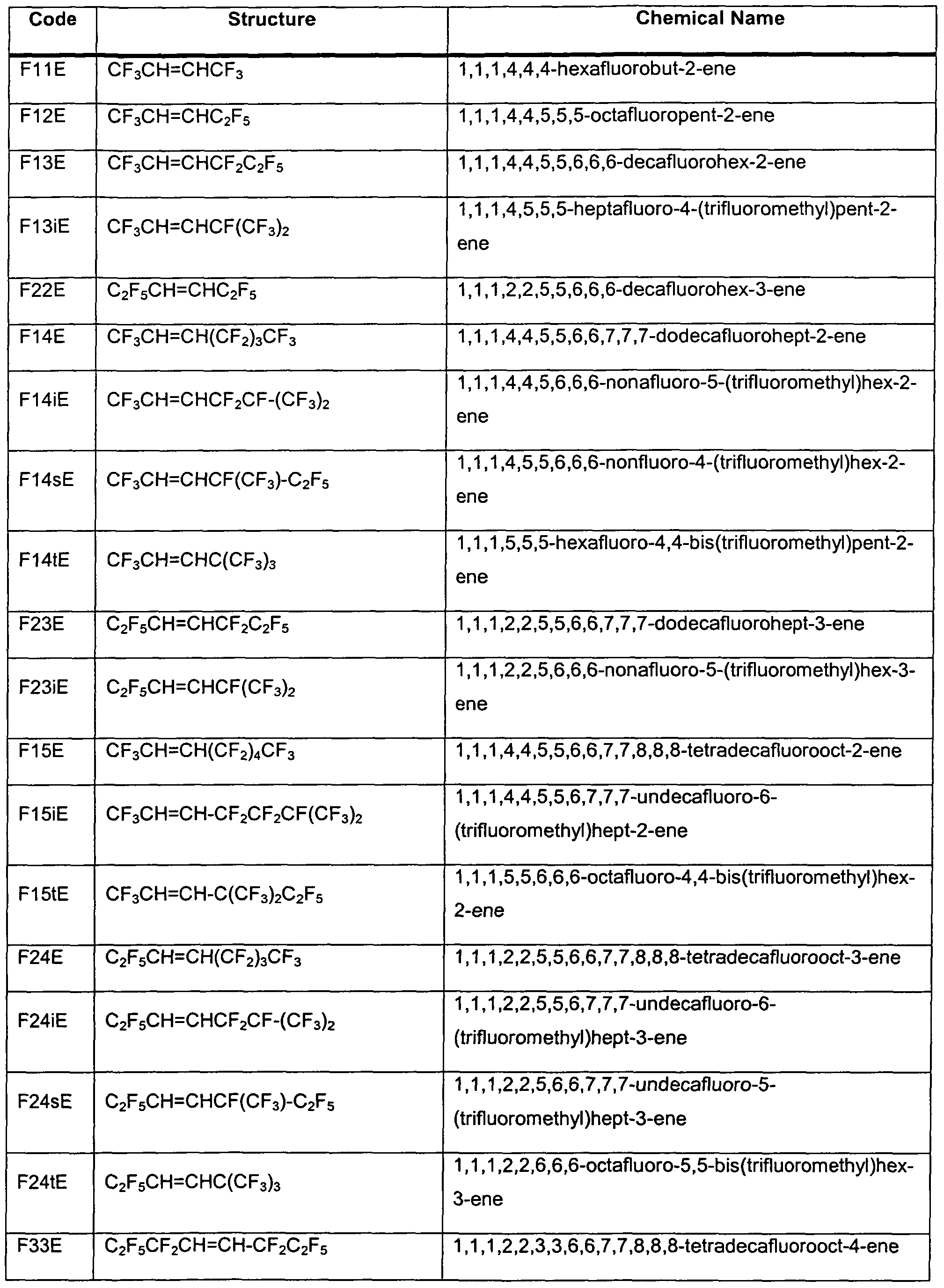
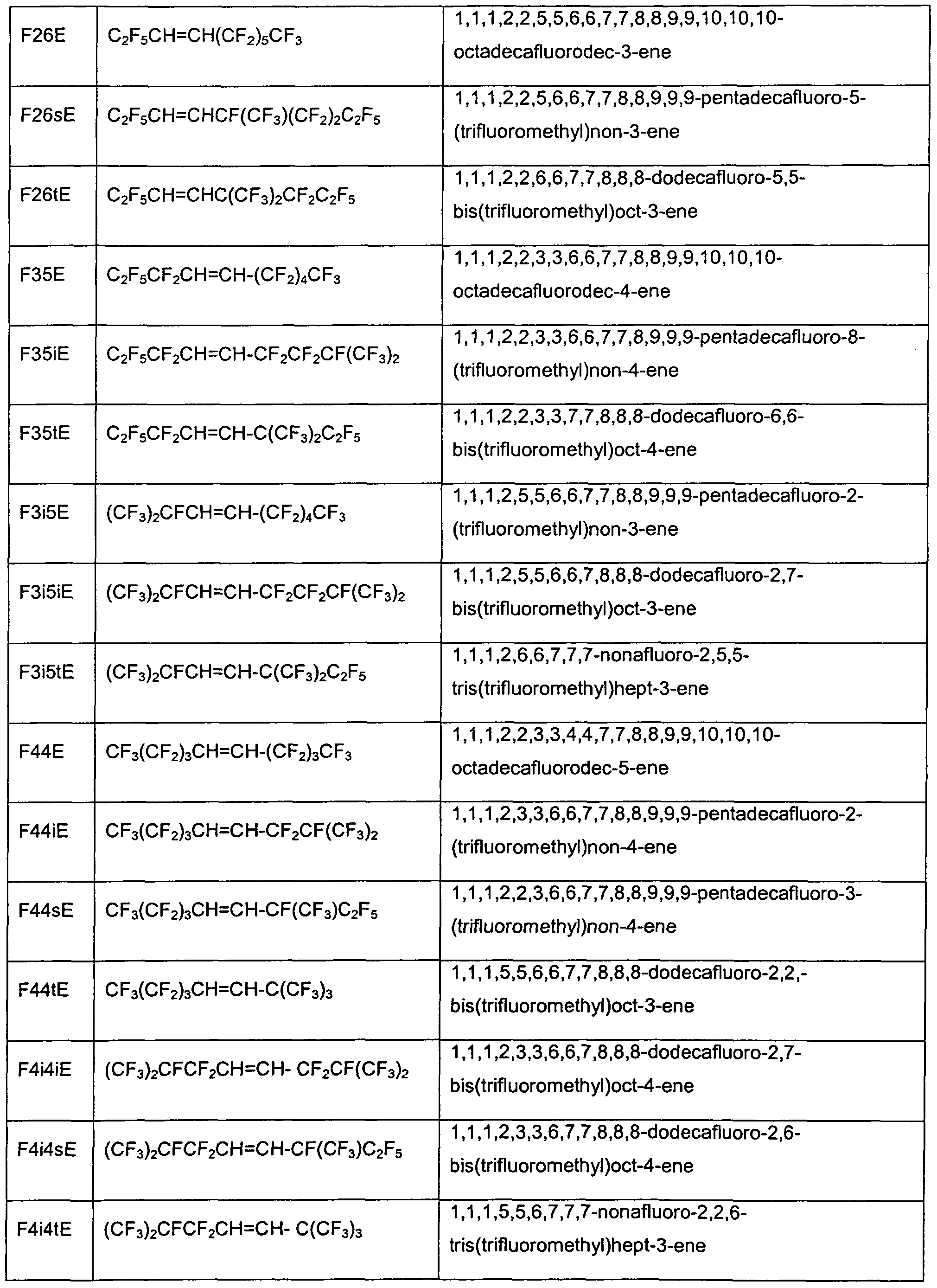
- Representative fluoroolefins include but are not limited to all compounds as listed in Table 1 , Table 2, and Table 3.
- R 1 and R 2 groups include, but are not limited to, CF 3 , C 2 F 5, CF 2 CF 2 CF 3 , CF(CF 3 ) 2 , CF 2 CF 2 CF 2 CF 3 , CF(CF 3 )CF 2 CF 3 , CF 2 CF(CF 3 ) 2 , C(CF 3 ) 3 , CF 2 CF 2 CF 2 CF 3 , CF 2 CF 2 CF(CF 3 ) 2 , C(CF 3 ) 2 C 2 F 5 , CF 2 CF 2 CF 2 CF 2 CF 2 CF 3 , CF(CF 3 ) CF 2 CF 2 C 2 F 5 , and C(CFs) 2 CF 2 C 2 F 5 .
- the fluoroolefins of Formula I have at least about 4 carbon atoms in the molecule. In another embodiment, the fluoroolefins of Formula I have at least about 5 carbon atoms in the molecule.
- Exemplary, non-limiting Formula I compounds are presented in Table 1.
- the contacting of a perfluoroalkyl iodide with a perfluoroalkyltrihydroolefin may take place in batch mode by combining the reactants in a suitable reaction vessel capable of operating under the autogenous pressure of the reactants and products at reaction 15 temperature.
- Suitable reaction vessels include fabricated from stainless steels, in particular of the austenitic type, and the well-known high nickel alloys such as Monel® nickel-copper alloys, Hastelloy® nickel based alloys and Inconel® nickel-chromium alloys.
- reaction may take be conducted in semi-batch 20 mode in which the perfluoroalkyltrihydroolefin reactant is added to the perfluoroalkyl iodide reactant by means of a suitable addition apparatus such as a pump at the reaction temperature.
- a suitable addition apparatus such as a pump at the reaction temperature.
- the ratio of perfluoroalkyl iodide to perfluoroalkyltrihydroolefin should be between about 1:1 to about 4:1 , preferably from about 1.5:1 to 25 2.5:1. Ratios less than 1.5:1 tend to result in large amounts of the 2:1 adduct as reported by Jeanneaux, et. al. in Journal of Fluorine Chemistry, Vol. 4, pages 261-270 (1974).
- Preferred temperatures for contacting of said perfluoroalkyl iodide with said perfluoroalkyltrihydroolefin are preferably within the range of about 15O 0 C to 300°C, preferably from about 170 0 C to about 250 0 C, and most preferably from about 180 0 C to about 230 0 C.
- Suitable contact times for the reaction of the perfluoroalkyl iodide with the perfluoroalkyltrihydroolefin are from about 0.5 hour to 18 hours, preferably from about 4 to about 12 hours.
- the trihydroiodoperfluoroalkane prepared by reaction of the perfluoroalkyl iodide with the perfluoroalkyltrihydroolefin may be used directly in the dehydroiodination step or may preferably be recovered and purified by distillation prior to the dehydroiodination step.
- the dehydroiodination step is carried out by contacting the trihydroiodoperfluoroalkane with a basic substance.
- Suitable basic substances include alkali metal hydroxides (e.g., sodium hydroxide or potassium hydroxide), alkali metal oxide (for example, sodium oxide), alkaline earth metal hydroxides (e.g., calcium hydroxide), alkaline earth metal oxides (e.g., calcium oxide), alkali metal alkoxides (e.g., sodium methoxide or sodium ethoxide), aqueous ammonia, sodium amide, or mixtures of basic substances such as soda lime.
- Preferred basic substances are sodium hydroxide and potassium hydroxide.
- the contacting of the trihydroiodoperfluoroalkane with a basic substance may take place in the liquid phase preferably in the presence of a solvent capable of dissolving at least a portion of both reactants.
- Solvents suitable for the dehydroiodination step include one or more polar organic solvents such as alcohols (e.g., methanol, ethanol, n-propanol, isopropanol, n-butanol, isobutanol, and tertiary butanol), nitriles (e.g., acetonitrile, propionitrile, butyronitrile, benzonitrile, or adiponitrile), dimethyl sulfoxide, N,N-dimethylformamide, N.N-dimethylacetamide, or sulfolane.
- solvents e.g., methanol, ethanol, n-propanol, isopropanol, n-butanol, isobutanol, and tertiary butanol
- nitriles e.g., acetonitrile, propionitrile, butyronitrile, benzonitrile
- the dehydroiodination reaction may be carried out by addition of one of the reactants (either the basic substance or the trihydroiodoperfluoroalkane) to the other reactant in a suitable reaction vessel.
- the reaction may be fabricated from glass, ceramic, or metal and is preferably agitated with an impeller or stirring mechanism.
- Temperatures suitable for the dehydroiodination reaction are from about 10 0 C to about 100 0 C, preferably from about 20 0 C to about 7O 0 C.
- the dehydroiodination reaction may be carried out at ambient pressure or at reduced or elevated pressure.
- dehydroiodination reactions in which the compound of Formula I is distilled out of the reaction vessel as it is formed.
- the dehydroiodination reaction may be conducted by contacting an aqueous solution of said basic substance with a solution of the trihydroiodoperfluoroalkane in one or more organic solvents of lower polarity such as an alkane (e.g., hexane, heptane, or octane), aromatic hydrocarbon (e.g., toluene), halogenated hydrocarbon (e.g., methylene chloride, chloroform, carbon tetrachloride, or perchloroethylene), or ether (e.g., diethyl ether, methyl tert-butyl ether, tetrahydrofuran, 2-methyl tetrahydrofuran, dioxane, dimethoxyethane, diglyme, or tetraglyme) in the presence of a phase transfer catalyst.
- an alkane e.g., hexane, heptane, or oc
- Suitable phase transfer catalysts include quaternary ammonium halides (e.g., tetrabutylammonium bromide, tetrabutylammonium hydrosulfate, triethylbenzylammonium chloride, dodecyltrimethylammonium chloride, and tricaprylylmethylammonium chloride), quaternary phosphonium halides (e.g., triphenylmethylphosphonium bromide and tetraphenylphosphonium chloride), or cyclic polyether compounds known in the art as crown ethers (e.g., 18-crown-6 and 15-crown-5).
- quaternary ammonium halides e.g., tetrabutylammonium bromide, tetrabutylammonium hydrosulfate, triethylbenzylammonium chloride, dodecyltrimethylammonium chloride, and tricaprylylmethylam
- the dehydroiodination reaction may be conducted in the absence of solvent by adding the trihydroiodoperfluoroalkane to a solid or liquid basic substance.
- Suitable reaction times for the dehydroiodination reactions are from about 15 minutes to about six hours or more depending on the solubility of the reactants.
- the dehydroiodination reaction is rapid and requires about 30 minutes to about three hours for completion.
- the compound of formula I may be recovered from the dehydroiodination reaction mixture by phase separation after addition of water, by distillation, or by a combination thereof.
- the fluoroolefins of Formula II have at least about 3 carbon atoms in the molecule.
- the fluoroolefins of Formula Il have at least about 4 carbon atoms in the molecule.
- the fluoroolefins of Formula Il have at least about 5 carbon atoms in the molecule.
- Representative cyclic fluoroolefins of Formula Il are listed in Table 2.
- compositions of the present invention may comprise a single compound of Formula I or formula II, for example, one of the compounds in Table 1 or Table 2, or may comprise a combination of compounds of Formula I or formula II.
- fluoroolefins may comprise those compounds listed in Table 3. TABLE 3
- 1 ,1 ,1 ,4,4-pentafluoro-2-butene may be prepared from 1 ,1 ,1 ,2,4,4- hexafluorobutane (CHF 2 CH 2 CHFCF 3 ) by dehydrofluorination over solid KOH in the vapor phase at room temperature.
- 1 ,1 ,1 ,2,4,4-hexafluorobutane is described in US 6,066,768, incorporated herein by reference.
- 1 ,1 ,1 ,4,4,4-hexafluoro-2-butene may be prepared from 1 ,1 ,1 ,4,4,4- hexafluoro-2-iodobutane (CF 3 CHICH 2 CF 3 ) by reaction with KOH using a phase transfer catalyst at about 60 0 C.
- 3,4,4,5,5,5-hexafluoro-2-pentene may be prepared by dehydrofluorination of 1 ,1 ,1 ,2,2,3,3-heptafluoropentane (CF 3 CF 2 CF 2 CH 2 CH 3 ) using solid KOH or over a carbon catalyst at 200- 300 0 C.
- 1 ,1 ,1 ,2,3,4-hexafluoro-2-butene may be prepared by dehydrofluorination of 1 ,1 ,1 , 2,3,3,4-heptafluorobutane (CH 2 FCF 2 CHFCF 3 ) using solid KOH.
- 1 ,1 ,1 ,2,4,4-hexafluoro-2-butene may be prepared by dehydrofluorination of 1 ,1 ,1 ,2,2,4,4-heptafluorobutane (CHF 2 CH 2 CF 2 CF 3 ) using solid KOH.
- 1 ,1 ,1 ,3,4,4-hexafluoro2-butene may be prepared by dehydrofluorination of 1 ,1 ,1 ,3,3,4,4-heptafluorobutane (CF 3 CH 2 CF 2 CHF 2 ) using solid KOH.
- 1 ,1 ,1 ,2,4-pentafluoro-2-butene may be prepared by dehydrofluorination of 1 ,1 ,1 , 2,2,3-hexafluorobutane (CH 2 FCH 2 CF 2 CF 3 ) using solid KOH.
- 1 ,1 ,1 ,3,4-pentafluoro-2-butene may be prepared by dehydrofluorination of 1,1 ,1 , 3,3,4-hexafluorobutane (CF 3 CH 2 CF 2 CH 2 F) using solid KOH.
- 1 ,1 ,1 ,3-tetrafluoro-2-butene may be prepared by reacting 1 ,1 ,1 ,3,3- pentafluorobutane ( CF 3 CH 2 CF 2 CH 3 ) with aqueous KOH at 120 °C.
- 1 ,1 ,1 ,4,4,5,5,5-octafluoro-2-pentene may be prepared from
- 1 ,1 ,1 ,2,2,5,5,6,6,6-decafluoro-3-hexene may be prepared from 1 ,1 ,1 ,2,2,5,5,6,6,6-decafluoro-3-iodohexane (CF 3 CF 2 CHICH 2 CF 2 CF 3 ) by reaction with KOH using a phase transfer catalyst at about 60°C.
- perfluoroethyliodide CF 3 CF 2 I
- CF 3 CF 2 CH CH 2
- 1 ,1 ,1 , 4,5, 5,5-heptafluoro-4-(trifluoromethyl)-2-pentene may be prepared by the dehydrofluorination of 1 ,1 ,1 ,2,5,5,5-heptafluoro-4-iodo-2- (trifluoromethyl)-pentane (CF 3 CHICH 2 CF(CF 3 ⁇ ) with KOH in isopropanol.
- 2,3,3,4,4-pentafluoro-1-butene may be prepared by dehydrofluorination of 1 ,1 ,2,2,3, 3-hexafluorobutane over fluorided alumina at elevated temperature.
- 2, 3,3,4,4, 5,5,5-ocatafluoro-i-pentene may be prepared by dehydroflurination of 2,2, 3,3,4,4, 5, 5,5-nonafluoropentane over solid KOH.
- 5-octafluoro-1-pentene may be prepared by dehydrofluorination of 2,2,3, 3,4,4, 5, 5,5-nonafluoropentane over fluorided alumina at elevated temperature.
- the working fluid may further comprise at least one compound selected from hydrofluorocarbons, fluoroethers, hydrocarbons, dimethyl ether (DME), carbon dioxide (CO 2 ), ammonia (NH 3 ), and iodotrifluoromethane (CF 3 I).
- the working fluid may further comprise hydrofluorocarbons comprising at least one saturated compound containing carbon, hydrogen, and fluorine.
- hydrofluorocarbons having 1 to 7 carbon atoms and having a normal boiling point of from about -90 0 C to about 8O 0 C.
- Hydrofluorocarbons are commercial products available from a number of sources or may be prepared by methods known in the art.
- hydrofluorocarbon compounds include but are not limited to fluoromethane (CH 3 F, HFC-41), difluoromethane (CH 2 F 2 , HFC-32), trifluoromethane (CHF 3 , HFC-23), pentafluoroethane (CF 3 CHF 2 , HFC-125), 1,1,2,2-tetrafluoroethane (CHF 2 CHF 2 , HFC-134), 1,1,1,2-tetrafluoroethane (CF 3 CH 2 F, HFC-134a), 1,1,1-trifluoroethane (CF 3 CH 3 , HFC-143a), 1,1-difluoroethane (CHF 2 CH 3 , HFC-152a), fluoroethane (CH 3 CH 2 F, HFC-161), 1,1,1,2,2,3,3- heptafluoropropane (CF 3 CF 2 CHF 2 , HFC-227ca), 1,1,1,2,3,3,3- heptafluoro
- working fluids may further comprise fluoroethers comprising at least one compound having carbon, fluorine, oxygen and optionally hydrogen, chlorine, bromine or iodine.
- fluoroethers are commercially available or may be produced by methods known in the art.
- fluoroethers include but are not limited to nonafluoromethoxybutane (C 4 FgOCH 3 , any or all possible isomers or mixtures thereof); nonafluoroethoxybutane (C 4 FgOC 2 H 5 , any or all possible isomers or mixtures thereof); 2-difluoromethoxy-1 ,1 ,1 ,2-tetrafluoroethane (HFOC-236eaE ⁇ , Or CHF 2 OCHFCF 3 ); 1 ,1-difluoro-2-methoxyethane (HFOC-272fbE ⁇ ,CH 3 OCH 2 CHF 2 ); 1 ,1 ,1 ,3,3,3-hexafluoro-2-
- working fluids may further comprise hydrocarbons comprising compounds having only carbon and hydrogen. Of particular utility are compounds having 3 to 7 carbon atoms. Hydrocarbons are commercially available through numerous chemical suppliers. Representative hydrocarbons include but are not limited to propane, n-butane, isobutane, cyclobutane, n-pentane, 2-methylbutane, 2,2-dimethylpropane, cyclopentane, n-hexane, 2-methylpentane, 2,2- dimethylbutane, 2,3-dimethylbutane, 3-methylpentane, cyclohexane, n- heptane, and cycloheptane.
- the working fluid may comprise hydrocarbons containing heteroatoms, such as dimethylether (DME, CH 3 OCH 3 ). DME is commercially available.
- working fluids may further comprise carbon dioxide (CO 2 ), which is commercially available from various sources or may be prepared by methods known in the art.
- CO 2 carbon dioxide
- working fluids may further comprise ammonia (NH 3 ), which is commercially available from various sources or may be prepared by methods known in the art.
- the working fluid further comprises at least one compound selected from hydrofluorocarbons, fluoroethers, hydrocarbons, dimethyl ether (DME), carbon dioxide (CO 2 ), ammonia (NH 3 ), and iodotrifluoromethane (CF 3 I).
- the working fluid comprises 1 ,2,3,3,3- pentafluoropropene (HFC-1225ye). In another embodiment, the working fluid further comprises difluoromethane (HFC-32). In yet another embodiment, the working fluid further comprises 1 ,1 ,1 ,2-tetrafluoroethane (HFC-134a).
- the working fluid comprises 2,3,3,3- tetrafluoropropene (HFC-1234yf). In another embodiment, the working fluid comprises HFC-1225ye and HFC-1234yf.
- the working fluid comprises 1 ,3,3,3- tetrafluoropropene (HFC-1234ze). In another embodiment, the working fluid comprises E-HFC-1234ze (or trans-HFC-1234ze). In yet another embodiment, the working fluid further comprises at least one compound from the group consisting of HFC-134a, HFC-32, HFC-125, HFC-152a, and CF 3 I.
- working fluids may comprise a composition selected from the group consisting of: HFC-32 and HFC-1225ye; HFC-1234yf and CF 3 I; HFC-32, HFC-134a, and HFC-1225ye; HFC-32, HFC-125, and HFC-1225ye;
- HFC-32, HFC-1225ye, and HFC-1234yf
- HFC-125, HFC-1225ye, and HFC-1234yf are HFC-125, HFC-1225ye, and HFC-1234yf;
- HFC-32, HFC-125, and HFC-1234yf HFC-32, HFC-134a, and HFC-1234yf;
- HFC-152a n-butane, and HFC-1234yf
- HFC-134a propane, and HFC-1234yf
- HFC-125, HFC-152a, and HFC-1234yf are HFC-125, HFC-152a, and HFC-1234yf;
- HFC-125, HFC-134a, and HFC-1234yf are HFC-125, HFC-134a, and HFC-1234yf;
- HFC-32, HFC-1234ze, and HFC-1234yf are HFC-32, HFC-1234ze, and HFC-1234yf;
- HFC-125, HFC-1234ze, and HFC-1234yf HFC-32, HFC-1234ze, HFC-1234yf, and CF 3 I;
- HFC-134a HFC-1234ze, and HFC-1234yf
- HFC-125 and HFC-1234ze HFC-32, HFC-125, and HFC-1234ze;
- HFC-32, HFC-134a, and HFC-1234ze
- HFC-152a, HFC-134a, and HFC-1234ze HFC-152a, n-butane, and HFC-1234ze;
- HFC-125, HFC-152a, and HFC-1234ze are HFC-125, HFC-134a, and HFC-1234ze.
- the working fluid was a blend of 95% by weight HFC-1225ye and 5% by weight of HFC-32.
- Each system had a condenser, evaporator, compressor and a thermal expansion device.
- the ambient air temperature was 30 0 C at the evaporator and the condenser inlets. Tests were performed for 2 compressor speeds, 1000 and 2000 rpm, and for 3 vehicle speeds: 25, 30, and 36 km/h.
- the volumetric flow rate of air on the evaporator was 380 m 3 /h.
- the cooling capacity for the system with an IHX shows an increase of 4 to 7% as compared to the system with no IHX.
- the COP also showed an increase of 2.5 to 4% for the system with the IHX as compared to a system with no IHX.
- Cooling performance is calculated for HFC-134a and HFC-1234yf both with and without an IHX.
- the conditions used are as follows: Condenser temperature 55 0 C
- the subcooling difference arises from the differences in molecular weight, liquid density and liquid heat capacity for HFC-1234yf as compared to HFC-134a. Based on these parameters it was estimated that there would be a difference in subcoolingachieved with the different compounds. When the HFC-134a subcool was set to 5 ° C, the corresponding subcooling for HFC-1234yf was calculated to be 5.8 ° C.
Abstract
Description


Claims
Priority Applications (11)
| Application Number | Priority Date | Filing Date | Title |
|---|---|---|---|
| CA2682312A CA2682312C (en) | 2007-05-11 | 2008-05-09 | Method for exchanging heat in a vapor compression heat transfer system and a vapor compression heat transfer system comprising an intermediate heat exchanger with a dual-row evaporator or condenser |
| CN200880015513A CN101680691A (en) | 2007-05-11 | 2008-05-09 | Method for exchanging heat in a vapor compression heat transfer system and a vapor compression heat transfer system comprising an intermediate heat exchanger with a dual-row evaporator or condenser |
| KR1020097025754A KR101513319B1 (en) | 2007-05-11 | 2008-05-09 | 2 method for exchanging heat in a vapor compression heat transfer system and a vapor compression heat transfer system comprising an intermediate heat exchanger with a dual-row evaporator or condenser |
| ES08767666.4T ES2575130T3 (en) | 2007-05-11 | 2008-05-09 | Method for heat exchange in a steam compression heat transfer system and a steam compression heat transfer system comprising an intermediate heat exchanger with a double row evaporator or condenser |
| JP2010507484A JP2010526982A (en) | 2007-05-11 | 2008-05-09 | Heat exchange method in a vapor compression heat transfer system and a vapor compression heat exchange system including an intermediate heat exchanger using a double row evaporator or double row condenser |
| EP24158471.3A EP4349694A2 (en) | 2007-01-31 | 2008-05-09 | A vapor compression heat transfer system |
| EP22209806.3A EP4160127B1 (en) | 2007-01-31 | 2008-05-09 | A vapor compression heat transfer system |
| EP08767666.4A EP2145150B8 (en) | 2007-05-11 | 2008-05-09 | Method for exchanging heat in a vapor compression heat transfer system and a vapor compression heat transfer system comprising an intermediate heat exchanger with a dual-row evaporator or condenser |
| BRPI0810282A BRPI0810282A2 (en) | 2007-05-11 | 2008-05-09 | "method for heat exchange and heat transfer systems" |
| MX2009012100A MX345550B (en) | 2007-05-11 | 2008-05-09 | Method for exchanging heat in a vapor compression heat transfer system and a vapor compression heat transfer system comprising an intermediate heat exchanger with a dual-row evaporator or condenser. |
| EP16164723.5A EP3091320B1 (en) | 2007-05-11 | 2008-05-09 | A vapor compression heat transfer system |
Applications Claiming Priority (6)
| Application Number | Priority Date | Filing Date | Title |
|---|---|---|---|
| US92882607P | 2007-05-11 | 2007-05-11 | |
| US60/928,826 | 2007-05-11 | ||
| US98856207P | 2007-11-16 | 2007-11-16 | |
| US60/988,562 | 2007-11-16 | ||
| PCT/US2007/025675 WO2008085314A2 (en) | 2006-12-19 | 2007-12-17 | Dual row heat exchanger and automobile bumper incorporating the same |
| USPCT/US2007/025675 | 2007-12-17 |
Publications (2)
| Publication Number | Publication Date |
|---|---|
| WO2008140809A2 true WO2008140809A2 (en) | 2008-11-20 |
| WO2008140809A3 WO2008140809A3 (en) | 2009-04-30 |
Family
ID=39870623
Family Applications (1)
| Application Number | Title | Priority Date | Filing Date |
|---|---|---|---|
| PCT/US2008/006043 WO2008140809A2 (en) | 2007-01-31 | 2008-05-09 | Method for exchanging heat in a vapor compression heat transfer system and a vapor compression heat transfer system comprising an intermediate heat exchanger with a dual-row evaporator or condenser |
Country Status (11)
| Country | Link |
|---|---|
| US (5) | US20090120619A1 (en) |
| EP (4) | EP4349694A2 (en) |
| JP (1) | JP2010526982A (en) |
| KR (1) | KR101513319B1 (en) |
| CN (2) | CN101680691A (en) |
| AR (1) | AR066522A1 (en) |
| BR (1) | BRPI0810282A2 (en) |
| CA (3) | CA2944695C (en) |
| ES (2) | ES2575130T3 (en) |
| MX (1) | MX345550B (en) |
| WO (1) | WO2008140809A2 (en) |
Cited By (19)
| Publication number | Priority date | Publication date | Assignee | Title |
|---|---|---|---|---|
| WO2010100254A1 (en) * | 2009-03-06 | 2010-09-10 | Solvay Fluor Gmbh | Use of unsaturated hydrofluorocarbons |
| JP2010255906A (en) * | 2009-04-23 | 2010-11-11 | Sanden Corp | Refrigerating cycle |
| WO2011030027A1 (en) | 2009-09-11 | 2011-03-17 | Arkema France | Low-temperature and average-temperature refrigeration |
| WO2011030026A1 (en) | 2009-09-11 | 2011-03-17 | Arkema France | Binary refrigerating fluid |
| WO2011056824A3 (en) * | 2009-11-03 | 2011-07-07 | E.I. Du Pont De Nemours And Company | Cascade refrigeration system with fluoroolefin refrigerant |
| GB2481443A (en) * | 2010-06-25 | 2011-12-28 | Mexichem Amanco Holding Sa | Heat transfer compositions |
| EP2407736A1 (en) * | 2009-03-12 | 2012-01-18 | Mitsubishi Heavy Industries, Ltd. | Heat pump device |
| JP2013504642A (en) * | 2009-09-11 | 2013-02-07 | アルケマ フランス | Use of ternary composition |
| EP2558544A1 (en) | 2010-04-16 | 2013-02-20 | E.I. Du Pont De Nemours And Company | Composition comprising 2,3,3,3-tetrafluoropropene and 1,1,1,2-tetrafluoroethane, chillers containing same and methods of producing cooling therein |
| JP2013521368A (en) * | 2010-03-02 | 2013-06-10 | アルケマ フランス | Heat transfer fluid for centrifugal compressors |
| US8926856B2 (en) | 2010-02-16 | 2015-01-06 | Mexichem Amanco Holding S.A. De C.V. | Heat transfer compositions |
| US8999190B2 (en) | 2007-10-12 | 2015-04-07 | Mexichem Amanco Holding S.A. De C.V. | Heat transfer compositions |
| US9175202B2 (en) | 2010-02-16 | 2015-11-03 | Mexichem Amanco Holding S.A. De C.V. | Heat transfer compositions |
| EP2475737B1 (en) | 2009-09-11 | 2016-05-18 | Arkema France | Heat transfer method |
| EP2516578B1 (en) | 2009-12-21 | 2016-06-22 | The Chemours Company FC, LLC | Compositions comprising tetrafluoropropene and difluoromethane and uses thereof |
| US9599381B2 (en) | 2008-10-08 | 2017-03-21 | Arkema France | Heat transfer fluid |
| EP2246649B1 (en) | 2008-02-29 | 2017-07-19 | Daikin Industries, Ltd. | Refrigerating apparatus |
| US10035938B2 (en) | 2009-09-11 | 2018-07-31 | Arkema France | Heat transfer fluid replacing R-134a |
| EP3734190A4 (en) * | 2017-12-25 | 2021-01-06 | Mitsubishi Electric Corporation | Heat exchanger and refrigeration cycle device |
Families Citing this family (43)
| Publication number | Priority date | Publication date | Assignee | Title |
|---|---|---|---|---|
| CN101351538A (en) * | 2005-11-01 | 2009-01-21 | 纳幕尔杜邦公司 | Solvent compositions comprising unsaturated fluorinated hydrocarbons |
| DE102006004870A1 (en) * | 2006-02-02 | 2007-08-16 | Siltronic Ag | Semiconductor layer structure and method for producing a semiconductor layer structure |
| ES2652604T3 (en) | 2006-02-28 | 2018-02-05 | The Chemours Company Fc, Llc | Azeotropic compositions comprising fluorinated compounds for cleaning applications |
| US8974688B2 (en) * | 2009-07-29 | 2015-03-10 | Honeywell International Inc. | Compositions and methods for refrigeration |
| WO2008140809A2 (en) | 2007-05-11 | 2008-11-20 | E. I. Du Pont De Nemours And Company | Method for exchanging heat in a vapor compression heat transfer system and a vapor compression heat transfer system comprising an intermediate heat exchanger with a dual-row evaporator or condenser |
| US7641808B2 (en) | 2007-08-23 | 2010-01-05 | E.I. Du Pont De Nemours And Company | Azeotropic compositions comprising fluorinated olefins for cleaning applications |
| US8512591B2 (en) | 2007-10-12 | 2013-08-20 | Mexichem Amanco Holding S.A. De C.V. | Heat transfer compositions |
| US8628681B2 (en) | 2007-10-12 | 2014-01-14 | Mexichem Amanco Holding S.A. De C.V. | Heat transfer compositions |
| FR2942237B1 (en) * | 2009-02-13 | 2013-01-04 | Arkema France | METHOD FOR HEATING AND / OR AIR CONDITIONING A VEHICLE |
| US9074115B2 (en) * | 2009-08-28 | 2015-07-07 | Mexichem Amanco Holding S.A. De C.V. | Heat transfer compositions |
| GB0915004D0 (en) * | 2009-08-28 | 2009-09-30 | Ineos Fluor Holdings Ltd | Heat transfer composition |
| FR2950071B1 (en) * | 2009-09-11 | 2012-02-03 | Arkema France | TERNARY COMPOSITIONS FOR LOW CAPACITY REFRIGERATION |
| FR2950070B1 (en) | 2009-09-11 | 2011-10-28 | Arkema France | TERNARY COMPOSITIONS FOR HIGH CAPACITY REFRIGERATION |
| KR101733256B1 (en) * | 2009-09-16 | 2017-05-08 | 이 아이 듀폰 디 네모아 앤드 캄파니 | Chiller apparatus containing trans-1,1,1,4,4,4-hexafluoro-2-butene and methods of producing cooling therein |
| GB201002619D0 (en) * | 2010-02-16 | 2010-03-31 | Ineos Fluor Holdings Ltd | Heat transfer compositions |
| FR2959997B1 (en) | 2010-05-11 | 2012-06-08 | Arkema France | HEAT TRANSFER FLUIDS AND THEIR USE IN COUNTER-CURRENT HEAT EXCHANGERS |
| FR2959999B1 (en) | 2010-05-11 | 2012-07-20 | Arkema France | HEAT TRANSFER FLUIDS AND THEIR USE IN COUNTER-CURRENT HEAT EXCHANGERS |
| ES2546062T3 (en) | 2010-05-20 | 2015-09-18 | Mexichem Fluor S.A. De C.V. | Heat transfer compositions |
| CN102947409A (en) | 2010-05-20 | 2013-02-27 | 墨西哥化学阿玛科股份有限公司 | Heat transfer compositions |
| FR2964977B1 (en) | 2010-09-20 | 2013-11-01 | Arkema France | COMPOSITION BASED ON 3,3,3-TETRAFLUOROPROPENE |
| CN103180675B (en) * | 2010-10-22 | 2015-06-03 | 法雷奥日本株式会社 | Refrigeration cycle and condenser with supercooling unit |
| US20120119136A1 (en) * | 2010-11-12 | 2012-05-17 | Honeywell International Inc. | Low gwp heat transfer compositions |
| FR2976289B1 (en) * | 2011-06-07 | 2013-05-24 | Arkema France | BINARY COMPOSITIONS OF 1,3,3,3-TETRAFLUOROPROPENE AND AMMONIA |
| US20130104575A1 (en) * | 2011-11-02 | 2013-05-02 | E I Du Pont De Nemours And Company | Use of compositions comprising 1,1,1,2,3-pentafluoropropane and optionally z-1,1,1,4,4,4-hexafluoro-2-butene in high temperature heat pumps |
| US20130333402A1 (en) * | 2012-06-18 | 2013-12-19 | GM Global Technology Operations LLC | Climate control systems for motor vehicles and methods of operating the same |
| US20140116083A1 (en) * | 2012-10-29 | 2014-05-01 | Myungjin Chung | Refrigerator |
| EP2970735A4 (en) * | 2013-03-15 | 2016-11-23 | Honeywell Int Inc | Heat transfer compositions and methods |
| JP6381890B2 (en) * | 2013-10-25 | 2018-08-29 | 三菱重工サーマルシステムズ株式会社 | Refrigerant circulation device, refrigerant circulation method, and isomerization suppression method |
| US10443912B2 (en) | 2013-10-25 | 2019-10-15 | Mitsubishi Heavy Industries Thermal Systems, Ltd. | Refrigerant circulation device, method for circulating refrigerant and acid suppression method |
| EP3572758B1 (en) | 2014-02-21 | 2023-04-05 | Rolls-Royce Corporation | Microchannel heat exchangers for gas turbine intercooling and condensing |
| US10330364B2 (en) | 2014-06-26 | 2019-06-25 | Hudson Technologies, Inc. | System and method for retrofitting a refrigeration system from HCFC to HFC refrigerant |
| US20170333941A1 (en) * | 2014-10-28 | 2017-11-23 | President And Fellows Of Harvard College | High energy efficiency phase change device using convex surface features |
| CN105820799A (en) * | 2015-01-05 | 2016-08-03 | 浙江省化工研究院有限公司 | Environment-friendly type refrigeration composition containing HFO-1234ze(E) |
| CN107072106A (en) * | 2016-12-28 | 2017-08-18 | 浙江海洋大学 | Unmanned boat circuit system fire prevention heat sink and fire prevention cool-down method |
| EP3674389A4 (en) * | 2017-08-25 | 2021-06-09 | AGC Inc. | Solvent composition, cleaning method, method for producing coated substrate, and heat transfer medium |
| WO2019056855A1 (en) * | 2017-09-20 | 2019-03-28 | 杭州三花家电热管理系统有限公司 | Heat exchange assembly, heat exchange system, and indoor heating system |
| EP3717588A4 (en) * | 2017-11-30 | 2021-08-11 | Honeywell International Inc. | Heat transfer compositions, methods, and systems |
| CN110343509B (en) * | 2018-04-02 | 2021-09-14 | 江西天宇化工有限公司 | Non-combustible mixed refrigerant capable of reducing greenhouse effect and application thereof |
| CN110343510B (en) | 2018-04-02 | 2021-06-04 | 江西天宇化工有限公司 | Non-flammable mixed refrigerant with low-temperature chamber effect and application thereof |
| CN109945292B (en) * | 2019-03-18 | 2021-05-25 | 山东大学 | Double-heat-source two-stage compression heat pump hot water system with auxiliary compressor and method |
| JP2022084964A (en) * | 2019-04-03 | 2022-06-08 | ダイキン工業株式会社 | Refrigerant cycle device |
| EP3742073B1 (en) * | 2019-05-21 | 2022-03-30 | Carrier Corporation | Refrigeration apparatus and use thereof |
| AU2022370363A1 (en) * | 2021-10-21 | 2024-04-18 | The Chemours Company Fc, Llc | Compositions comprising 2,3,3,3-tetrafluoropropene |
Family Cites Families (61)
| Publication number | Priority date | Publication date | Assignee | Title |
|---|---|---|---|---|
| US1507560A (en) | 1921-10-05 | 1924-09-09 | Island | |
| GB230612A (en) | 1924-02-21 | 1925-03-19 | Thomas Edgar Wood | Improvements in and relating to heat transmission apparatus |
| US2120764A (en) * | 1936-09-25 | 1938-06-14 | York Ice Machinery Corp | Refrigeration |
| FR1346189A (en) | 1963-02-01 | 1963-12-13 | Gevaert Photo Prod Nv | Industrial manufacture of ketene |
| GB1084795A (en) | 1963-09-13 | 1967-09-27 | Joseph Kaye & Company Inc | Apparatus for compressing refrigerant vapour |
| GB1027195A (en) | 1963-11-07 | 1966-04-27 | Metallurg Engineers Ltd | Improvements in heat exchangers |
| US3877242A (en) * | 1973-10-11 | 1975-04-15 | Int Refrigeration Engineers | Harvest control unit for an ice-making machine |
| DE2535490C2 (en) | 1975-08-08 | 1982-09-16 | Linde Ag, 6200 Wiesbaden | Refrigeration unit |
| GB1595616A (en) | 1977-01-21 | 1981-08-12 | Hitachi Ltd | Air conditioning system |
| JPS55133167U (en) * | 1979-03-13 | 1980-09-20 | ||
| US4316366A (en) * | 1980-04-21 | 1982-02-23 | Carrier Corporation | Method and apparatus for integrating components of a refrigeration system |
| JPS62255762A (en) | 1986-04-30 | 1987-11-07 | 株式会社日立製作所 | Air conditioner |
| FR2614686A1 (en) | 1987-04-28 | 1988-11-04 | Puicervert Luc | Heat exchanger |
| JP3030036B2 (en) | 1989-08-23 | 2000-04-10 | 昭和アルミニウム株式会社 | Double heat exchanger |
| US5529116A (en) | 1989-08-23 | 1996-06-25 | Showa Aluminum Corporation | Duplex heat exchanger |
| JPH03279763A (en) * | 1990-03-27 | 1991-12-10 | Showa Alum Corp | Multiple heat exchanger |
| JPH05170135A (en) * | 1991-12-18 | 1993-07-09 | Mazda Motor Corp | Front body structure for automobile |
| WO1995016656A1 (en) | 1993-12-14 | 1995-06-22 | E.I. Du Pont De Nemours And Company | Process for perhalofluorinated butanes |
| DE69533120D1 (en) | 1994-05-30 | 2004-07-15 | Mitsubishi Electric Corp | Coolant circulation system |
| JPH1019418A (en) * | 1996-07-03 | 1998-01-23 | Toshiba Corp | Refrigerator with deep freezer |
| JPH1199964A (en) | 1997-09-29 | 1999-04-13 | Aisin Seiki Co Ltd | Vehicle front end module structure |
| DE19813673B4 (en) * | 1998-03-27 | 2004-01-29 | Daimlerchrysler Ag | Method and device for heating and cooling a useful space of a motor vehicle |
| US6327866B1 (en) * | 1998-12-30 | 2001-12-11 | Praxair Technology, Inc. | Food freezing method using a multicomponent refrigerant |
| US6176102B1 (en) * | 1998-12-30 | 2001-01-23 | Praxair Technology, Inc. | Method for providing refrigeration |
| JP2001121941A (en) | 1999-10-28 | 2001-05-08 | Denso Corp | On-vehicle mounting structure of heat exchanger |
| JP2001263831A (en) * | 2000-03-24 | 2001-09-26 | Mitsubishi Electric Corp | Refrigerating cycle system |
| KR100426640B1 (en) * | 2000-09-25 | 2004-04-08 | 주식회사 템피아 | Refrigeration cycle |
| JP2003021432A (en) | 2001-07-09 | 2003-01-24 | Zexel Valeo Climate Control Corp | Condenser |
| US6748759B2 (en) * | 2001-08-02 | 2004-06-15 | Ho-Hsin Wu | High efficiency heat exchanger |
| WO2003040640A1 (en) * | 2001-11-08 | 2003-05-15 | Zexel Valeo Climate Control Corporation | Heat exchanger and tube for heat exchanger |
| JP2004011959A (en) * | 2002-06-04 | 2004-01-15 | Sanyo Electric Co Ltd | Supercritical refrigerant cycle equipment |
| KR101235583B1 (en) | 2002-10-25 | 2013-02-22 | 허니웰 인터내셔널 인코포레이티드 | Compositions Containing Fluorine Substituted Olefins |
| US20040089839A1 (en) | 2002-10-25 | 2004-05-13 | Honeywell International, Inc. | Fluorinated alkene refrigerant compositions |
| KR100496376B1 (en) * | 2003-03-31 | 2005-06-22 | 한명범 | Improvement system of energy efficiency for use in a refrigeration cycle |
| JP4124136B2 (en) * | 2003-04-21 | 2008-07-23 | 株式会社デンソー | Refrigerant evaporator |
| US7089760B2 (en) * | 2003-05-27 | 2006-08-15 | Calsonic Kansei Corporation | Air-conditioner |
| JP2005037054A (en) * | 2003-07-15 | 2005-02-10 | Sanyo Electric Co Ltd | Heat exchanger for refrigerant cycle device |
| US7592494B2 (en) * | 2003-07-25 | 2009-09-22 | Honeywell International Inc. | Process for the manufacture of 1,3,3,3-tetrafluoropropene |
| JP2005083741A (en) * | 2003-09-05 | 2005-03-31 | Lg Electronics Inc | Air conditioner having heat exchanger and refrigerant switching means |
| GB2405688A (en) * | 2003-09-05 | 2005-03-09 | Applied Design & Eng Ltd | Refrigerator |
| US7276177B2 (en) * | 2004-01-14 | 2007-10-02 | E.I. Dupont De Nemours And Company | Hydrofluorocarbon refrigerant compositions and uses thereof |
| US7605117B2 (en) * | 2004-04-16 | 2009-10-20 | Honeywell International Inc. | Methods of replacing refrigerant |
| ES2392333T3 (en) * | 2004-04-16 | 2012-12-07 | Honeywell International Inc. | Azeotrope-like tetrafluoropropene and trifluoroiodomethane compositions |
| US7629306B2 (en) | 2004-04-29 | 2009-12-08 | Honeywell International Inc. | Compositions comprising tetrafluoropropene and carbon dioxide |
| US7028490B2 (en) * | 2004-05-28 | 2006-04-18 | Ut-Batelle, Llc | Water-heating dehumidifier |
| JP2006183889A (en) * | 2004-12-27 | 2006-07-13 | Nissan Motor Light Truck Co Ltd | Heat pump device |
| US20060243945A1 (en) * | 2005-03-04 | 2006-11-02 | Minor Barbara H | Compositions comprising a fluoroolefin |
| US20060243944A1 (en) * | 2005-03-04 | 2006-11-02 | Minor Barbara H | Compositions comprising a fluoroolefin |
| US7569170B2 (en) | 2005-03-04 | 2009-08-04 | E.I. Du Pont De Nemours And Company | Compositions comprising a fluoroolefin |
| GB0507953D0 (en) * | 2005-04-21 | 2005-05-25 | Thermal Energy Systems Ltd | Heat pump |
| CN1710356A (en) * | 2005-06-21 | 2005-12-21 | 上海本家空调系统有限公司 | Heat-recovery energy-storage type water source heat pump |
| TWI645031B (en) * | 2005-06-24 | 2018-12-21 | 哈尼威爾國際公司 | Compositions containing fluorine substituted olefins amd uses thereof |
| JP2007032949A (en) * | 2005-07-28 | 2007-02-08 | Showa Denko Kk | Heat exchanger |
| JP4661449B2 (en) * | 2005-08-17 | 2011-03-30 | 株式会社デンソー | Ejector refrigeration cycle |
| JP4840681B2 (en) | 2005-09-16 | 2011-12-21 | 株式会社ヴァレオジャパン | Heat exchanger |
| US7476771B2 (en) * | 2005-11-01 | 2009-01-13 | E.I. Du Pont De Nemours + Company | Azeotrope compositions comprising 2,3,3,3-tetrafluoropropene and hydrogen fluoride and uses thereof |
| US7708903B2 (en) | 2005-11-01 | 2010-05-04 | E.I. Du Pont De Nemours And Company | Compositions comprising fluoroolefins and uses thereof |
| US7617766B2 (en) | 2006-08-25 | 2009-11-17 | Sunbeam Products, Inc. | Baby food maker |
| CA2661007A1 (en) | 2006-09-01 | 2008-03-06 | E.I. Du Pont De Nemours And Company | Method for circulating selected heat transfer fluids through a closed loop cycle |
| EP2097702A2 (en) | 2006-12-19 | 2009-09-09 | E. I. Du Pont de Nemours and Company | Dual row heat exchanger and automobile bumper incorporating the same |
| WO2008140809A2 (en) | 2007-05-11 | 2008-11-20 | E. I. Du Pont De Nemours And Company | Method for exchanging heat in a vapor compression heat transfer system and a vapor compression heat transfer system comprising an intermediate heat exchanger with a dual-row evaporator or condenser |
-
2008
- 2008-05-09 WO PCT/US2008/006043 patent/WO2008140809A2/en active Application Filing
- 2008-05-09 MX MX2009012100A patent/MX345550B/en active IP Right Grant
- 2008-05-09 EP EP24158471.3A patent/EP4349694A2/en active Pending
- 2008-05-09 CN CN200880015513A patent/CN101680691A/en active Pending
- 2008-05-09 AR ARP080101986A patent/AR066522A1/en not_active Application Discontinuation
- 2008-05-09 CA CA2944695A patent/CA2944695C/en active Active
- 2008-05-09 EP EP08767666.4A patent/EP2145150B8/en not_active Revoked
- 2008-05-09 ES ES08767666.4T patent/ES2575130T3/en active Active
- 2008-05-09 JP JP2010507484A patent/JP2010526982A/en active Pending
- 2008-05-09 EP EP16164723.5A patent/EP3091320B1/en active Active
- 2008-05-09 CA CA2682312A patent/CA2682312C/en active Active
- 2008-05-09 KR KR1020097025754A patent/KR101513319B1/en active IP Right Grant
- 2008-05-09 BR BRPI0810282A patent/BRPI0810282A2/en not_active IP Right Cessation
- 2008-05-09 CA CA3002834A patent/CA3002834C/en active Active
- 2008-05-09 ES ES16164723T patent/ES2935119T3/en active Active
- 2008-05-09 EP EP22209806.3A patent/EP4160127B1/en active Active
- 2008-05-09 CN CN201510800415.1A patent/CN105333653A/en active Pending
- 2008-05-12 US US12/119,023 patent/US20090120619A1/en not_active Abandoned
-
2011
- 2011-08-11 US US13/207,557 patent/US20110290447A1/en not_active Abandoned
-
2018
- 2018-03-29 US US15/939,644 patent/US11624534B2/en active Active
-
2022
- 2022-12-19 US US18/084,201 patent/US11867436B2/en active Active
-
2023
- 2023-11-17 US US18/512,520 patent/US20240125524A1/en active Pending
Non-Patent Citations (1)
| Title |
|---|
| None |
Cited By (39)
| Publication number | Priority date | Publication date | Assignee | Title |
|---|---|---|---|---|
| US8999190B2 (en) | 2007-10-12 | 2015-04-07 | Mexichem Amanco Holding S.A. De C.V. | Heat transfer compositions |
| EP2246649B2 (en) † | 2008-02-29 | 2023-10-25 | Daikin Industries, Ltd. | Refrigerating apparatus |
| EP2246649B1 (en) | 2008-02-29 | 2017-07-19 | Daikin Industries, Ltd. | Refrigerating apparatus |
| US11130893B2 (en) | 2008-10-08 | 2021-09-28 | Arkema France | Heat transfer fluid |
| US9599381B2 (en) | 2008-10-08 | 2017-03-21 | Arkema France | Heat transfer fluid |
| WO2010100254A1 (en) * | 2009-03-06 | 2010-09-10 | Solvay Fluor Gmbh | Use of unsaturated hydrofluorocarbons |
| EP2407736A1 (en) * | 2009-03-12 | 2012-01-18 | Mitsubishi Heavy Industries, Ltd. | Heat pump device |
| EP2407736A4 (en) * | 2009-03-12 | 2012-09-12 | Mitsubishi Heavy Ind Ltd | Heat pump device |
| JP2010255906A (en) * | 2009-04-23 | 2010-11-11 | Sanden Corp | Refrigerating cycle |
| US10125296B2 (en) | 2009-09-11 | 2018-11-13 | Arkema France | Binary refrigerating fluid |
| JP2019214725A (en) * | 2009-09-11 | 2019-12-19 | アルケマ フランス | Binary refrigerating fluid |
| WO2011030027A1 (en) | 2009-09-11 | 2011-03-17 | Arkema France | Low-temperature and average-temperature refrigeration |
| WO2011030026A1 (en) | 2009-09-11 | 2011-03-17 | Arkema France | Binary refrigerating fluid |
| EP2475734B1 (en) * | 2009-09-11 | 2021-04-07 | Arkema France | Binary refrigerating fluid |
| US10858562B2 (en) | 2009-09-11 | 2020-12-08 | Arkema France | Binary refrigerating fluid |
| JP2013504642A (en) * | 2009-09-11 | 2013-02-07 | アルケマ フランス | Use of ternary composition |
| US10358592B2 (en) | 2009-09-11 | 2019-07-23 | Arkema France | Heat transfer method |
| US10316231B2 (en) | 2009-09-11 | 2019-06-11 | Arkema France | Low-temperature and average-temperature refrigeration |
| EP2475737B1 (en) | 2009-09-11 | 2016-05-18 | Arkema France | Heat transfer method |
| EP2475735B1 (en) | 2009-09-11 | 2016-05-25 | Arkema France | Low-temperature and average-temperature refrigeration |
| US10035938B2 (en) | 2009-09-11 | 2018-07-31 | Arkema France | Heat transfer fluid replacing R-134a |
| US9884984B2 (en) | 2009-09-11 | 2018-02-06 | Arkema France | Binary refrigerating fluid |
| US9683157B2 (en) | 2009-09-11 | 2017-06-20 | Arkema France | Heat transfer method |
| WO2011056824A3 (en) * | 2009-11-03 | 2011-07-07 | E.I. Du Pont De Nemours And Company | Cascade refrigeration system with fluoroolefin refrigerant |
| EP2516578B1 (en) | 2009-12-21 | 2016-06-22 | The Chemours Company FC, LLC | Compositions comprising tetrafluoropropene and difluoromethane and uses thereof |
| US8926856B2 (en) | 2010-02-16 | 2015-01-06 | Mexichem Amanco Holding S.A. De C.V. | Heat transfer compositions |
| US9175202B2 (en) | 2010-02-16 | 2015-11-03 | Mexichem Amanco Holding S.A. De C.V. | Heat transfer compositions |
| JP2013521368A (en) * | 2010-03-02 | 2013-06-10 | アルケマ フランス | Heat transfer fluid for centrifugal compressors |
| EP2558544B1 (en) | 2010-04-16 | 2018-09-05 | The Chemours Company FC, LLC | Chillers containing a composition comprising 2,3,3,3-tetrafluoropropene and 1,1,1,2-tetrafluoroethane |
| EP2558544A1 (en) | 2010-04-16 | 2013-02-20 | E.I. Du Pont De Nemours And Company | Composition comprising 2,3,3,3-tetrafluoropropene and 1,1,1,2-tetrafluoroethane, chillers containing same and methods of producing cooling therein |
| US10844260B2 (en) | 2010-06-25 | 2020-11-24 | Mexichem Amanco Holding S.A. De C.V. | Heat transfer compositions |
| GB2481443A (en) * | 2010-06-25 | 2011-12-28 | Mexichem Amanco Holding Sa | Heat transfer compositions |
| GB2481443B (en) * | 2010-06-25 | 2012-10-17 | Mexichem Amanco Holding Sa | Heat transfer compositions |
| AU2011268772B2 (en) * | 2010-06-25 | 2014-03-06 | Mexichem Amanco Holding S.A. De C.V. | Heat transfer compositions |
| JP2013151683A (en) * | 2010-06-25 | 2013-08-08 | Mexichem Amanco Holding Sa De Cv | Heat transfer composition |
| US10266736B2 (en) | 2010-06-25 | 2019-04-23 | Mexichem Amanco Holding S.A. De C.V. | Heat transfer compositions |
| US11760911B2 (en) | 2010-06-25 | 2023-09-19 | Mexichem Amanco Holding S.A. De C.V. | Heat transfer compositions |
| JP2012007164A (en) * | 2010-06-25 | 2012-01-12 | Mexichem Amanco Holding Sa De Cv | Heat transfer composition |
| EP3734190A4 (en) * | 2017-12-25 | 2021-01-06 | Mitsubishi Electric Corporation | Heat exchanger and refrigeration cycle device |
Also Published As
| Publication number | Publication date |
|---|---|
| ES2935119T3 (en) | 2023-03-01 |
| EP4160127B1 (en) | 2024-02-28 |
| CA3002834C (en) | 2020-04-07 |
| CA2944695C (en) | 2018-06-12 |
| BRPI0810282A2 (en) | 2017-09-26 |
| EP2145150A2 (en) | 2010-01-20 |
| US20240125524A1 (en) | 2024-04-18 |
| AR066522A1 (en) | 2009-08-26 |
| US20110290447A1 (en) | 2011-12-01 |
| CN101680691A (en) | 2010-03-24 |
| CA2682312C (en) | 2016-11-22 |
| EP3091320B1 (en) | 2022-11-30 |
| EP2145150B8 (en) | 2016-08-10 |
| CA3002834A1 (en) | 2008-11-20 |
| EP4349694A2 (en) | 2024-04-10 |
| US20180231281A1 (en) | 2018-08-16 |
| EP2145150B1 (en) | 2016-04-13 |
| US20090120619A1 (en) | 2009-05-14 |
| KR101513319B1 (en) | 2015-04-17 |
| US20230235930A1 (en) | 2023-07-27 |
| WO2008140809A3 (en) | 2009-04-30 |
| MX2009012100A (en) | 2009-11-23 |
| KR20100029761A (en) | 2010-03-17 |
| EP3091320A1 (en) | 2016-11-09 |
| CA2682312A1 (en) | 2008-11-20 |
| MX345550B (en) | 2017-02-03 |
| EP4160127A1 (en) | 2023-04-05 |
| ES2575130T3 (en) | 2016-06-24 |
| US11867436B2 (en) | 2024-01-09 |
| US11624534B2 (en) | 2023-04-11 |
| JP2010526982A (en) | 2010-08-05 |
| CA2944695A1 (en) | 2008-11-20 |
| CN105333653A (en) | 2016-02-17 |
Similar Documents
| Publication | Publication Date | Title |
|---|---|---|
| US11867436B2 (en) | Method for exchanging heat in vapor compression heat transfer systems and vapor compression heat transfer systems comprising intermediate heat exchangers with dual-row evaporators or condensers | |
| AU2010315264B2 (en) | Cascade refrigeration system with fluoroolefin refrigerant | |
| US20110088418A1 (en) | Compositions comprising ionic liquids and fluoroolefins and use thereof in absorption cycle systems | |
| US20080314073A1 (en) | Method for leak detection in heat transfer systems |
Legal Events
| Date | Code | Title | Description |
|---|---|---|---|
| WWE | Wipo information: entry into national phase |
Ref document number: 200880015513.2 Country of ref document: CN |
|
| 121 | Ep: the epo has been informed by wipo that ep was designated in this application |
Ref document number: 08767666 Country of ref document: EP Kind code of ref document: A2 |
|
| ENP | Entry into the national phase |
Ref document number: 2682312 Country of ref document: CA |
|
| WWE | Wipo information: entry into national phase |
Ref document number: 6444/DELNP/2009 Country of ref document: IN |
|
| WWE | Wipo information: entry into national phase |
Ref document number: 2008767666 Country of ref document: EP |
|
| WWE | Wipo information: entry into national phase |
Ref document number: MX/A/2009/012100 Country of ref document: MX |
|
| WWE | Wipo information: entry into national phase |
Ref document number: 2010507484 Country of ref document: JP |
|
| NENP | Non-entry into the national phase |
Ref country code: DE |
|
| ENP | Entry into the national phase |
Ref document number: 20097025754 Country of ref document: KR Kind code of ref document: A |
|
| WWE | Wipo information: entry into national phase |
Ref document number: A200909749 Country of ref document: UA |
|
| REG | Reference to national code |
Ref country code: BR Ref legal event code: B01E Ref document number: PI0810282 Country of ref document: BR |
|
| ENP | Entry into the national phase |
Ref document number: PI0810282 Country of ref document: BR Kind code of ref document: A2 Effective date: 20091110 |