EP3091320B1 - A vapor compression heat transfer system - Google Patents
A vapor compression heat transfer system Download PDFInfo
- Publication number
- EP3091320B1 EP3091320B1 EP16164723.5A EP16164723A EP3091320B1 EP 3091320 B1 EP3091320 B1 EP 3091320B1 EP 16164723 A EP16164723 A EP 16164723A EP 3091320 B1 EP3091320 B1 EP 3091320B1
- Authority
- EP
- European Patent Office
- Prior art keywords
- working fluid
- row
- tube
- outlet
- inlet
- Prior art date
- Legal status (The legal status is an assumption and is not a legal conclusion. Google has not performed a legal analysis and makes no representation as to the accuracy of the status listed.)
- Active
Links
- 238000007906 compression Methods 0.000 title claims description 21
- 230000006835 compression Effects 0.000 title claims description 20
- 239000012530 fluid Substances 0.000 claims description 97
- LCGLNKUTAGEVQW-UHFFFAOYSA-N Dimethyl ether Chemical compound COC LCGLNKUTAGEVQW-UHFFFAOYSA-N 0.000 claims description 18
- 239000007788 liquid Substances 0.000 claims description 17
- 238000000034 method Methods 0.000 claims description 15
- 238000001816 cooling Methods 0.000 claims description 14
- FXRLMCRCYDHQFW-UHFFFAOYSA-N 2,3,3,3-tetrafluoropropene Chemical compound FC(=C)C(F)(F)F FXRLMCRCYDHQFW-UHFFFAOYSA-N 0.000 claims description 13
- QGZKDVFQNNGYKY-UHFFFAOYSA-N Ammonia Chemical compound N QGZKDVFQNNGYKY-UHFFFAOYSA-N 0.000 claims description 13
- CURLTUGMZLYLDI-UHFFFAOYSA-N Carbon dioxide Chemical compound O=C=O CURLTUGMZLYLDI-UHFFFAOYSA-N 0.000 claims description 12
- 150000001875 compounds Chemical class 0.000 claims description 10
- 229910002092 carbon dioxide Inorganic materials 0.000 claims description 8
- 239000001569 carbon dioxide Substances 0.000 claims description 8
- 229930195733 hydrocarbon Natural products 0.000 claims description 7
- 150000002430 hydrocarbons Chemical class 0.000 claims description 7
- VPAYJEUHKVESSD-UHFFFAOYSA-N trifluoroiodomethane Chemical compound FC(F)(F)I VPAYJEUHKVESSD-UHFFFAOYSA-N 0.000 claims description 7
- 229920001774 Perfluoroether Polymers 0.000 claims description 6
- 229910021529 ammonia Inorganic materials 0.000 claims description 4
- 229910000069 nitrogen hydride Inorganic materials 0.000 claims description 4
- 238000010438 heat treatment Methods 0.000 claims description 3
- 238000001704 evaporation Methods 0.000 claims 2
- LVGUZGTVOIAKKC-UHFFFAOYSA-N 1,1,1,2-tetrafluoroethane Chemical compound FCC(F)(F)F LVGUZGTVOIAKKC-UHFFFAOYSA-N 0.000 description 13
- 238000004378 air conditioning Methods 0.000 description 11
- RWRIWBAIICGTTQ-UHFFFAOYSA-N difluoromethane Chemical compound FCF RWRIWBAIICGTTQ-UHFFFAOYSA-N 0.000 description 9
- 238000005057 refrigeration Methods 0.000 description 9
- 239000003570 air Substances 0.000 description 6
- XPDWGBQVDMORPB-UHFFFAOYSA-N Fluoroform Chemical compound FC(F)F XPDWGBQVDMORPB-UHFFFAOYSA-N 0.000 description 5
- 239000000203 mixture Substances 0.000 description 5
- NBVXSUQYWXRMNV-UHFFFAOYSA-N fluoromethane Chemical compound FC NBVXSUQYWXRMNV-UHFFFAOYSA-N 0.000 description 4
- 229910052751 metal Inorganic materials 0.000 description 4
- 239000002184 metal Substances 0.000 description 4
- MSSNHSVIGIHOJA-UHFFFAOYSA-N pentafluoropropane Chemical compound FC(F)CC(F)(F)F MSSNHSVIGIHOJA-UHFFFAOYSA-N 0.000 description 4
- YFMFNYKEUDLDTL-UHFFFAOYSA-N 1,1,1,2,3,3,3-heptafluoropropane Chemical compound FC(F)(F)C(F)C(F)(F)F YFMFNYKEUDLDTL-UHFFFAOYSA-N 0.000 description 3
- NSGXIBWMJZWTPY-UHFFFAOYSA-N 1,1,1,3,3,3-hexafluoropropane Chemical compound FC(F)(F)CC(F)(F)F NSGXIBWMJZWTPY-UHFFFAOYSA-N 0.000 description 3
- WXGNWUVNYMJENI-UHFFFAOYSA-N 1,1,2,2-tetrafluoroethane Chemical compound FC(F)C(F)F WXGNWUVNYMJENI-UHFFFAOYSA-N 0.000 description 3
- NPNPZTNLOVBDOC-UHFFFAOYSA-N 1,1-difluoroethane Chemical compound CC(F)F NPNPZTNLOVBDOC-UHFFFAOYSA-N 0.000 description 3
- OKTJSMMVPCPJKN-UHFFFAOYSA-N Carbon Chemical compound [C] OKTJSMMVPCPJKN-UHFFFAOYSA-N 0.000 description 3
- IMNFDUFMRHMDMM-UHFFFAOYSA-N N-Heptane Chemical compound CCCCCCC IMNFDUFMRHMDMM-UHFFFAOYSA-N 0.000 description 3
- 229910052799 carbon Inorganic materials 0.000 description 3
- 239000007789 gas Substances 0.000 description 3
- DMEGYFMYUHOHGS-UHFFFAOYSA-N heptamethylene Natural products C1CCCCCC1 DMEGYFMYUHOHGS-UHFFFAOYSA-N 0.000 description 3
- 239000001257 hydrogen Substances 0.000 description 3
- 229910052739 hydrogen Inorganic materials 0.000 description 3
- 239000000463 material Substances 0.000 description 3
- GTLACDSXYULKMZ-UHFFFAOYSA-N pentafluoroethane Chemical compound FC(F)C(F)(F)F GTLACDSXYULKMZ-UHFFFAOYSA-N 0.000 description 3
- RIQRGMUSBYGDBL-UHFFFAOYSA-N 1,1,1,2,2,3,4,5,5,5-decafluoropentane Chemical compound FC(F)(F)C(F)C(F)C(F)(F)C(F)(F)F RIQRGMUSBYGDBL-UHFFFAOYSA-N 0.000 description 2
- SUAMPXQALWYDBK-UHFFFAOYSA-N 1,1,1,2,2,3-hexafluoropropane Chemical compound FCC(F)(F)C(F)(F)F SUAMPXQALWYDBK-UHFFFAOYSA-N 0.000 description 2
- FDOPVENYMZRARC-UHFFFAOYSA-N 1,1,1,2,2-pentafluoropropane Chemical compound CC(F)(F)C(F)(F)F FDOPVENYMZRARC-UHFFFAOYSA-N 0.000 description 2
- FYIRUPZTYPILDH-UHFFFAOYSA-N 1,1,1,2,3,3-hexafluoropropane Chemical compound FC(F)C(F)C(F)(F)F FYIRUPZTYPILDH-UHFFFAOYSA-N 0.000 description 2
- ZDCWZRQSHBQRGN-UHFFFAOYSA-N 1,1,1,2,3-pentafluoropropane Chemical compound FCC(F)C(F)(F)F ZDCWZRQSHBQRGN-UHFFFAOYSA-N 0.000 description 2
- WZLFPVPRZGTCKP-UHFFFAOYSA-N 1,1,1,3,3-pentafluorobutane Chemical compound CC(F)(F)CC(F)(F)F WZLFPVPRZGTCKP-UHFFFAOYSA-N 0.000 description 2
- PFFGXVGPSGJOBV-UHFFFAOYSA-N 1,1,1,3-tetrafluoropropane Chemical compound FCCC(F)(F)F PFFGXVGPSGJOBV-UHFFFAOYSA-N 0.000 description 2
- UJPMYEOUBPIPHQ-UHFFFAOYSA-N 1,1,1-trifluoroethane Chemical compound CC(F)(F)F UJPMYEOUBPIPHQ-UHFFFAOYSA-N 0.000 description 2
- LKLFXAVIFCLZQS-UHFFFAOYSA-N 1,1,2,2,3,3,4,4-octafluorobutane Chemical compound FC(F)C(F)(F)C(F)(F)C(F)F LKLFXAVIFCLZQS-UHFFFAOYSA-N 0.000 description 2
- AWTOFSDLNREIFS-UHFFFAOYSA-N 1,1,2,2,3-pentafluoropropane Chemical compound FCC(F)(F)C(F)F AWTOFSDLNREIFS-UHFFFAOYSA-N 0.000 description 2
- MWDWMQNTNBHJEI-UHFFFAOYSA-N 1,1,2,3,3-pentafluoropropane Chemical compound FC(F)C(F)C(F)F MWDWMQNTNBHJEI-UHFFFAOYSA-N 0.000 description 2
- HNRMPXKDFBEGFZ-UHFFFAOYSA-N 2,2-dimethylbutane Chemical compound CCC(C)(C)C HNRMPXKDFBEGFZ-UHFFFAOYSA-N 0.000 description 2
- ZFFMLCVRJBZUDZ-UHFFFAOYSA-N 2,3-dimethylbutane Chemical compound CC(C)C(C)C ZFFMLCVRJBZUDZ-UHFFFAOYSA-N 0.000 description 2
- AFABGHUZZDYHJO-UHFFFAOYSA-N 2-Methylpentane Chemical compound CCCC(C)C AFABGHUZZDYHJO-UHFFFAOYSA-N 0.000 description 2
- PFEOZHBOMNWTJB-UHFFFAOYSA-N 3-methylpentane Chemical compound CCC(C)CC PFEOZHBOMNWTJB-UHFFFAOYSA-N 0.000 description 2
- RGSFGYAAUTVSQA-UHFFFAOYSA-N Cyclopentane Chemical compound C1CCCC1 RGSFGYAAUTVSQA-UHFFFAOYSA-N 0.000 description 2
- PXGOKWXKJXAPGV-UHFFFAOYSA-N Fluorine Chemical compound FF PXGOKWXKJXAPGV-UHFFFAOYSA-N 0.000 description 2
- OFBQJSOFQDEBGM-UHFFFAOYSA-N Pentane Chemical compound CCCCC OFBQJSOFQDEBGM-UHFFFAOYSA-N 0.000 description 2
- ATUOYWHBWRKTHZ-UHFFFAOYSA-N Propane Chemical compound CCC ATUOYWHBWRKTHZ-UHFFFAOYSA-N 0.000 description 2
- 125000004432 carbon atom Chemical group C* 0.000 description 2
- DPYMFVXJLLWWEU-UHFFFAOYSA-N desflurane Chemical compound FC(F)OC(F)C(F)(F)F DPYMFVXJLLWWEU-UHFFFAOYSA-N 0.000 description 2
- 230000000694 effects Effects 0.000 description 2
- 229910052731 fluorine Inorganic materials 0.000 description 2
- 239000011737 fluorine Substances 0.000 description 2
- UHCBBWUQDAVSMS-UHFFFAOYSA-N fluoroethane Chemical compound CCF UHCBBWUQDAVSMS-UHFFFAOYSA-N 0.000 description 2
- UKACHOXRXFQJFN-UHFFFAOYSA-N heptafluoropropane Chemical compound FC(F)C(F)(F)C(F)(F)F UKACHOXRXFQJFN-UHFFFAOYSA-N 0.000 description 2
- 125000004435 hydrogen atom Chemical class [H]* 0.000 description 2
- NNPPMTNAJDCUHE-UHFFFAOYSA-N isobutane Chemical compound CC(C)C NNPPMTNAJDCUHE-UHFFFAOYSA-N 0.000 description 2
- QWTDNUCVQCZILF-UHFFFAOYSA-N isopentane Chemical compound CCC(C)C QWTDNUCVQCZILF-UHFFFAOYSA-N 0.000 description 2
- VLKZOEOYAKHREP-UHFFFAOYSA-N n-Hexane Chemical compound CCCCCC VLKZOEOYAKHREP-UHFFFAOYSA-N 0.000 description 2
- CRSOQBOWXPBRES-UHFFFAOYSA-N neopentane Chemical compound CC(C)(C)C CRSOQBOWXPBRES-UHFFFAOYSA-N 0.000 description 2
- OKIYQFLILPKULA-UHFFFAOYSA-N 1,1,1,2,2,3,3,4,4-nonafluoro-4-methoxybutane Chemical compound COC(F)(F)C(F)(F)C(F)(F)C(F)(F)F OKIYQFLILPKULA-UHFFFAOYSA-N 0.000 description 1
- MQQLAYMCXDAYFW-UHFFFAOYSA-N 1,1,1,2,2,3,3,4,5,6,6,7,7,7-tetradecafluoroheptane Chemical compound FC(F)(F)C(F)(F)C(F)C(F)C(F)(F)C(F)(F)C(F)(F)F MQQLAYMCXDAYFW-UHFFFAOYSA-N 0.000 description 1
- BJGMDDXEWGMYHD-UHFFFAOYSA-N 1,1,1,2,2,4,4,4-octafluorobutane Chemical compound FC(F)(F)CC(F)(F)C(F)(F)F BJGMDDXEWGMYHD-UHFFFAOYSA-N 0.000 description 1
- ZYAMKYAPIQPWQR-UHFFFAOYSA-N 1,1,1,2,2-pentafluoro-3-methoxypropane Chemical compound COCC(F)(F)C(F)(F)F ZYAMKYAPIQPWQR-UHFFFAOYSA-N 0.000 description 1
- INEMUVRCEAELBK-UHFFFAOYSA-N 1,1,1,2-tetrafluoropropane Chemical compound CC(F)C(F)(F)F INEMUVRCEAELBK-UHFFFAOYSA-N 0.000 description 1
- VNXYDFNVQBICRO-UHFFFAOYSA-N 1,1,1,3,3,3-hexafluoro-2-methoxypropane Chemical compound COC(C(F)(F)F)C(F)(F)F VNXYDFNVQBICRO-UHFFFAOYSA-N 0.000 description 1
- KDWQLICBSFIDRM-UHFFFAOYSA-N 1,1,1-trifluoropropane Chemical compound CCC(F)(F)F KDWQLICBSFIDRM-UHFFFAOYSA-N 0.000 description 1
- XWUSALIIUZARQE-UHFFFAOYSA-N 1,1,2,2-tetrafluoropropane Chemical compound CC(F)(F)C(F)F XWUSALIIUZARQE-UHFFFAOYSA-N 0.000 description 1
- AYNJDIUGIVKMNZ-UHFFFAOYSA-N 1,1,2,3-tetrafluoropropane Chemical compound FCC(F)C(F)F AYNJDIUGIVKMNZ-UHFFFAOYSA-N 0.000 description 1
- JDLOJZBMTBIATO-UHFFFAOYSA-N 1,1,3,3-tetrafluoropropane Chemical compound FC(F)CC(F)F JDLOJZBMTBIATO-UHFFFAOYSA-N 0.000 description 1
- CRGZRXUKXVTRNO-UHFFFAOYSA-N 1,1-difluoro-2-methoxyethane Chemical compound COCC(F)F CRGZRXUKXVTRNO-UHFFFAOYSA-N 0.000 description 1
- CTJAKAQLCQKBTC-UHFFFAOYSA-N 1,1-difluoropropane Chemical compound CCC(F)F CTJAKAQLCQKBTC-UHFFFAOYSA-N 0.000 description 1
- KRMPWJLLJZSRLO-UHFFFAOYSA-N 1,2,2,3-tetrafluoropropane Chemical compound FCC(F)(F)CF KRMPWJLLJZSRLO-UHFFFAOYSA-N 0.000 description 1
- OFHQVNFSKOBBGG-UHFFFAOYSA-N 1,2-difluoropropane Chemical compound CC(F)CF OFHQVNFSKOBBGG-UHFFFAOYSA-N 0.000 description 1
- OOLOYCGJRJFTPM-UHFFFAOYSA-N 1,3-difluoropropane Chemical compound FCCCF OOLOYCGJRJFTPM-UHFFFAOYSA-N 0.000 description 1
- DFUYAWQUODQGFF-UHFFFAOYSA-N 1-ethoxy-1,1,2,2,3,3,4,4,4-nonafluorobutane Chemical compound CCOC(F)(F)C(F)(F)C(F)(F)C(F)(F)F DFUYAWQUODQGFF-UHFFFAOYSA-N 0.000 description 1
- JRHNUZCXXOTJCA-UHFFFAOYSA-N 1-fluoropropane Chemical compound CCCF JRHNUZCXXOTJCA-UHFFFAOYSA-N 0.000 description 1
- YZXSQDNPKVBDOG-UHFFFAOYSA-N 2,2-difluoropropane Chemical compound CC(C)(F)F YZXSQDNPKVBDOG-UHFFFAOYSA-N 0.000 description 1
- SXYHZEQKWNODPB-UHFFFAOYSA-N 2-[difluoro(methoxy)methyl]-1,1,1,2,3,3,3-heptafluoropropane;1,1,1,2,2,3,3,4,4-nonafluoro-4-methoxybutane Chemical compound COC(F)(F)C(F)(F)C(F)(F)C(F)(F)F.COC(F)(F)C(F)(C(F)(F)F)C(F)(F)F SXYHZEQKWNODPB-UHFFFAOYSA-N 0.000 description 1
- RMFXYVDVYHFRRQ-UHFFFAOYSA-N 2-ethoxy-1,1,1,2,3,3,3-heptafluoropropane Chemical compound CCOC(F)(C(F)(F)F)C(F)(F)F RMFXYVDVYHFRRQ-UHFFFAOYSA-N 0.000 description 1
- PRNZBCYBKGCOFI-UHFFFAOYSA-N 2-fluoropropane Chemical compound CC(C)F PRNZBCYBKGCOFI-UHFFFAOYSA-N 0.000 description 1
- ZCYVEMRRCGMTRW-UHFFFAOYSA-N 7553-56-2 Chemical compound [I] ZCYVEMRRCGMTRW-UHFFFAOYSA-N 0.000 description 1
- WKBOTKDWSSQWDR-UHFFFAOYSA-N Bromine atom Chemical compound [Br] WKBOTKDWSSQWDR-UHFFFAOYSA-N 0.000 description 1
- ZAMOUSCENKQFHK-UHFFFAOYSA-N Chlorine atom Chemical compound [Cl] ZAMOUSCENKQFHK-UHFFFAOYSA-N 0.000 description 1
- RYGMFSIKBFXOCR-UHFFFAOYSA-N Copper Chemical compound [Cu] RYGMFSIKBFXOCR-UHFFFAOYSA-N 0.000 description 1
- 229910000881 Cu alloy Inorganic materials 0.000 description 1
- PMPVIKIVABFJJI-UHFFFAOYSA-N Cyclobutane Chemical compound C1CCC1 PMPVIKIVABFJJI-UHFFFAOYSA-N 0.000 description 1
- XDTMQSROBMDMFD-UHFFFAOYSA-N Cyclohexane Chemical compound C1CCCCC1 XDTMQSROBMDMFD-UHFFFAOYSA-N 0.000 description 1
- -1 HFC-254fb) Chemical compound 0.000 description 1
- UFHFLCQGNIYNRP-UHFFFAOYSA-N Hydrogen Chemical compound [H][H] UFHFLCQGNIYNRP-UHFFFAOYSA-N 0.000 description 1
- 229910052782 aluminium Inorganic materials 0.000 description 1
- XAGFODPZIPBFFR-UHFFFAOYSA-N aluminium Chemical compound [Al] XAGFODPZIPBFFR-UHFFFAOYSA-N 0.000 description 1
- 239000012080 ambient air Substances 0.000 description 1
- QVGXLLKOCUKJST-UHFFFAOYSA-N atomic oxygen Chemical compound [O] QVGXLLKOCUKJST-UHFFFAOYSA-N 0.000 description 1
- 238000009835 boiling Methods 0.000 description 1
- GDTBXPJZTBHREO-UHFFFAOYSA-N bromine Substances BrBr GDTBXPJZTBHREO-UHFFFAOYSA-N 0.000 description 1
- 229910052794 bromium Inorganic materials 0.000 description 1
- 239000000460 chlorine Substances 0.000 description 1
- 229910052801 chlorine Inorganic materials 0.000 description 1
- 229910052802 copper Inorganic materials 0.000 description 1
- 239000010949 copper Substances 0.000 description 1
- 238000010586 diagram Methods 0.000 description 1
- 238000006073 displacement reaction Methods 0.000 description 1
- 229920001971 elastomer Polymers 0.000 description 1
- 239000000806 elastomer Substances 0.000 description 1
- 125000005842 heteroatom Chemical group 0.000 description 1
- 239000011630 iodine Substances 0.000 description 1
- 229910052740 iodine Inorganic materials 0.000 description 1
- 239000001282 iso-butane Substances 0.000 description 1
- IJDNQMDRQITEOD-UHFFFAOYSA-N n-butane Chemical compound CCCC IJDNQMDRQITEOD-UHFFFAOYSA-N 0.000 description 1
- 239000001301 oxygen Substances 0.000 description 1
- 229910052760 oxygen Inorganic materials 0.000 description 1
- 229920000642 polymer Polymers 0.000 description 1
- 239000001294 propane Substances 0.000 description 1
- 239000003507 refrigerant Substances 0.000 description 1
- 239000012779 reinforcing material Substances 0.000 description 1
- 229920006395 saturated elastomer Polymers 0.000 description 1
- DFEYYRMXOJXZRJ-UHFFFAOYSA-N sevoflurane Chemical compound FCOC(C(F)(F)F)C(F)(F)F DFEYYRMXOJXZRJ-UHFFFAOYSA-N 0.000 description 1
- 239000000126 substance Substances 0.000 description 1
- 238000009834 vaporization Methods 0.000 description 1
- 230000008016 vaporization Effects 0.000 description 1
Images

Classifications
-
- F—MECHANICAL ENGINEERING; LIGHTING; HEATING; WEAPONS; BLASTING
- F25—REFRIGERATION OR COOLING; COMBINED HEATING AND REFRIGERATION SYSTEMS; HEAT PUMP SYSTEMS; MANUFACTURE OR STORAGE OF ICE; LIQUEFACTION SOLIDIFICATION OF GASES
- F25B—REFRIGERATION MACHINES, PLANTS OR SYSTEMS; COMBINED HEATING AND REFRIGERATION SYSTEMS; HEAT PUMP SYSTEMS
- F25B40/00—Subcoolers, desuperheaters or superheaters
- F25B40/02—Subcoolers
-
- F—MECHANICAL ENGINEERING; LIGHTING; HEATING; WEAPONS; BLASTING
- F25—REFRIGERATION OR COOLING; COMBINED HEATING AND REFRIGERATION SYSTEMS; HEAT PUMP SYSTEMS; MANUFACTURE OR STORAGE OF ICE; LIQUEFACTION SOLIDIFICATION OF GASES
- F25B—REFRIGERATION MACHINES, PLANTS OR SYSTEMS; COMBINED HEATING AND REFRIGERATION SYSTEMS; HEAT PUMP SYSTEMS
- F25B40/00—Subcoolers, desuperheaters or superheaters
-
- F—MECHANICAL ENGINEERING; LIGHTING; HEATING; WEAPONS; BLASTING
- F25—REFRIGERATION OR COOLING; COMBINED HEATING AND REFRIGERATION SYSTEMS; HEAT PUMP SYSTEMS; MANUFACTURE OR STORAGE OF ICE; LIQUEFACTION SOLIDIFICATION OF GASES
- F25B—REFRIGERATION MACHINES, PLANTS OR SYSTEMS; COMBINED HEATING AND REFRIGERATION SYSTEMS; HEAT PUMP SYSTEMS
- F25B49/00—Arrangement or mounting of control or safety devices
- F25B49/02—Arrangement or mounting of control or safety devices for compression type machines, plants or systems
- F25B49/027—Condenser control arrangements
-
- F—MECHANICAL ENGINEERING; LIGHTING; HEATING; WEAPONS; BLASTING
- F28—HEAT EXCHANGE IN GENERAL
- F28D—HEAT-EXCHANGE APPARATUS, NOT PROVIDED FOR IN ANOTHER SUBCLASS, IN WHICH THE HEAT-EXCHANGE MEDIA DO NOT COME INTO DIRECT CONTACT
- F28D1/00—Heat-exchange apparatus having stationary conduit assemblies for one heat-exchange medium only, the media being in contact with different sides of the conduit wall, in which the other heat-exchange medium is a large body of fluid, e.g. domestic or motor car radiators
- F28D1/02—Heat-exchange apparatus having stationary conduit assemblies for one heat-exchange medium only, the media being in contact with different sides of the conduit wall, in which the other heat-exchange medium is a large body of fluid, e.g. domestic or motor car radiators with heat-exchange conduits immersed in the body of fluid
- F28D1/04—Heat-exchange apparatus having stationary conduit assemblies for one heat-exchange medium only, the media being in contact with different sides of the conduit wall, in which the other heat-exchange medium is a large body of fluid, e.g. domestic or motor car radiators with heat-exchange conduits immersed in the body of fluid with tubular conduits
- F28D1/0408—Multi-circuit heat exchangers, e.g. integrating different heat exchange sections in the same unit or heat exchangers for more than two fluids
- F28D1/0426—Multi-circuit heat exchangers, e.g. integrating different heat exchange sections in the same unit or heat exchangers for more than two fluids with units having particular arrangement relative to the large body of fluid, e.g. with interleaved units or with adjacent heat exchange units in common air flow or with units extending at an angle to each other or with units arranged around a central element
- F28D1/0452—Combination of units extending one behind the other with units extending one beside or one above the other
-
- F—MECHANICAL ENGINEERING; LIGHTING; HEATING; WEAPONS; BLASTING
- F28—HEAT EXCHANGE IN GENERAL
- F28D—HEAT-EXCHANGE APPARATUS, NOT PROVIDED FOR IN ANOTHER SUBCLASS, IN WHICH THE HEAT-EXCHANGE MEDIA DO NOT COME INTO DIRECT CONTACT
- F28D1/00—Heat-exchange apparatus having stationary conduit assemblies for one heat-exchange medium only, the media being in contact with different sides of the conduit wall, in which the other heat-exchange medium is a large body of fluid, e.g. domestic or motor car radiators
- F28D1/02—Heat-exchange apparatus having stationary conduit assemblies for one heat-exchange medium only, the media being in contact with different sides of the conduit wall, in which the other heat-exchange medium is a large body of fluid, e.g. domestic or motor car radiators with heat-exchange conduits immersed in the body of fluid
- F28D1/04—Heat-exchange apparatus having stationary conduit assemblies for one heat-exchange medium only, the media being in contact with different sides of the conduit wall, in which the other heat-exchange medium is a large body of fluid, e.g. domestic or motor car radiators with heat-exchange conduits immersed in the body of fluid with tubular conduits
- F28D1/053—Heat-exchange apparatus having stationary conduit assemblies for one heat-exchange medium only, the media being in contact with different sides of the conduit wall, in which the other heat-exchange medium is a large body of fluid, e.g. domestic or motor car radiators with heat-exchange conduits immersed in the body of fluid with tubular conduits the conduits being straight
- F28D1/05316—Assemblies of conduits connected to common headers, e.g. core type radiators
- F28D1/05333—Assemblies of conduits connected to common headers, e.g. core type radiators with multiple rows of conduits or with multi-channel conduits
-
- F—MECHANICAL ENGINEERING; LIGHTING; HEATING; WEAPONS; BLASTING
- F28—HEAT EXCHANGE IN GENERAL
- F28D—HEAT-EXCHANGE APPARATUS, NOT PROVIDED FOR IN ANOTHER SUBCLASS, IN WHICH THE HEAT-EXCHANGE MEDIA DO NOT COME INTO DIRECT CONTACT
- F28D1/00—Heat-exchange apparatus having stationary conduit assemblies for one heat-exchange medium only, the media being in contact with different sides of the conduit wall, in which the other heat-exchange medium is a large body of fluid, e.g. domestic or motor car radiators
- F28D1/02—Heat-exchange apparatus having stationary conduit assemblies for one heat-exchange medium only, the media being in contact with different sides of the conduit wall, in which the other heat-exchange medium is a large body of fluid, e.g. domestic or motor car radiators with heat-exchange conduits immersed in the body of fluid
- F28D1/04—Heat-exchange apparatus having stationary conduit assemblies for one heat-exchange medium only, the media being in contact with different sides of the conduit wall, in which the other heat-exchange medium is a large body of fluid, e.g. domestic or motor car radiators with heat-exchange conduits immersed in the body of fluid with tubular conduits
- F28D1/053—Heat-exchange apparatus having stationary conduit assemblies for one heat-exchange medium only, the media being in contact with different sides of the conduit wall, in which the other heat-exchange medium is a large body of fluid, e.g. domestic or motor car radiators with heat-exchange conduits immersed in the body of fluid with tubular conduits the conduits being straight
- F28D1/0535—Heat-exchange apparatus having stationary conduit assemblies for one heat-exchange medium only, the media being in contact with different sides of the conduit wall, in which the other heat-exchange medium is a large body of fluid, e.g. domestic or motor car radiators with heat-exchange conduits immersed in the body of fluid with tubular conduits the conduits being straight the conduits having a non-circular cross-section
- F28D1/05366—Assemblies of conduits connected to common headers, e.g. core type radiators
- F28D1/05383—Assemblies of conduits connected to common headers, e.g. core type radiators with multiple rows of conduits or with multi-channel conduits
-
- F—MECHANICAL ENGINEERING; LIGHTING; HEATING; WEAPONS; BLASTING
- F28—HEAT EXCHANGE IN GENERAL
- F28D—HEAT-EXCHANGE APPARATUS, NOT PROVIDED FOR IN ANOTHER SUBCLASS, IN WHICH THE HEAT-EXCHANGE MEDIA DO NOT COME INTO DIRECT CONTACT
- F28D1/00—Heat-exchange apparatus having stationary conduit assemblies for one heat-exchange medium only, the media being in contact with different sides of the conduit wall, in which the other heat-exchange medium is a large body of fluid, e.g. domestic or motor car radiators
- F28D1/02—Heat-exchange apparatus having stationary conduit assemblies for one heat-exchange medium only, the media being in contact with different sides of the conduit wall, in which the other heat-exchange medium is a large body of fluid, e.g. domestic or motor car radiators with heat-exchange conduits immersed in the body of fluid
- F28D1/04—Heat-exchange apparatus having stationary conduit assemblies for one heat-exchange medium only, the media being in contact with different sides of the conduit wall, in which the other heat-exchange medium is a large body of fluid, e.g. domestic or motor car radiators with heat-exchange conduits immersed in the body of fluid with tubular conduits
- F28D1/053—Heat-exchange apparatus having stationary conduit assemblies for one heat-exchange medium only, the media being in contact with different sides of the conduit wall, in which the other heat-exchange medium is a large body of fluid, e.g. domestic or motor car radiators with heat-exchange conduits immersed in the body of fluid with tubular conduits the conduits being straight
- F28D1/0535—Heat-exchange apparatus having stationary conduit assemblies for one heat-exchange medium only, the media being in contact with different sides of the conduit wall, in which the other heat-exchange medium is a large body of fluid, e.g. domestic or motor car radiators with heat-exchange conduits immersed in the body of fluid with tubular conduits the conduits being straight the conduits having a non-circular cross-section
- F28D1/05366—Assemblies of conduits connected to common headers, e.g. core type radiators
- F28D1/05391—Assemblies of conduits connected to common headers, e.g. core type radiators with multiple rows of conduits or with multi-channel conduits combined with a particular flow pattern, e.g. multi-row multi-stage radiators
-
- F—MECHANICAL ENGINEERING; LIGHTING; HEATING; WEAPONS; BLASTING
- F25—REFRIGERATION OR COOLING; COMBINED HEATING AND REFRIGERATION SYSTEMS; HEAT PUMP SYSTEMS; MANUFACTURE OR STORAGE OF ICE; LIQUEFACTION SOLIDIFICATION OF GASES
- F25B—REFRIGERATION MACHINES, PLANTS OR SYSTEMS; COMBINED HEATING AND REFRIGERATION SYSTEMS; HEAT PUMP SYSTEMS
- F25B2339/00—Details of evaporators; Details of condensers
- F25B2339/04—Details of condensers
- F25B2339/046—Condensers with refrigerant heat exchange tubes positioned inside or around a vessel containing water or pcm to cool the refrigerant gas
-
- F—MECHANICAL ENGINEERING; LIGHTING; HEATING; WEAPONS; BLASTING
- F25—REFRIGERATION OR COOLING; COMBINED HEATING AND REFRIGERATION SYSTEMS; HEAT PUMP SYSTEMS; MANUFACTURE OR STORAGE OF ICE; LIQUEFACTION SOLIDIFICATION OF GASES
- F25B—REFRIGERATION MACHINES, PLANTS OR SYSTEMS; COMBINED HEATING AND REFRIGERATION SYSTEMS; HEAT PUMP SYSTEMS
- F25B2400/00—General features or devices for refrigeration machines, plants or systems, combined heating and refrigeration systems or heat-pump systems, i.e. not limited to a particular subgroup of F25B
- F25B2400/12—Inflammable refrigerants
- F25B2400/121—Inflammable refrigerants using R1234
-
- F—MECHANICAL ENGINEERING; LIGHTING; HEATING; WEAPONS; BLASTING
- F28—HEAT EXCHANGE IN GENERAL
- F28D—HEAT-EXCHANGE APPARATUS, NOT PROVIDED FOR IN ANOTHER SUBCLASS, IN WHICH THE HEAT-EXCHANGE MEDIA DO NOT COME INTO DIRECT CONTACT
- F28D21/00—Heat-exchange apparatus not covered by any of the groups F28D1/00 - F28D20/00
- F28D2021/0019—Other heat exchangers for particular applications; Heat exchange systems not otherwise provided for
- F28D2021/0068—Other heat exchangers for particular applications; Heat exchange systems not otherwise provided for for refrigerant cycles
- F28D2021/007—Condensers
-
- F—MECHANICAL ENGINEERING; LIGHTING; HEATING; WEAPONS; BLASTING
- F28—HEAT EXCHANGE IN GENERAL
- F28D—HEAT-EXCHANGE APPARATUS, NOT PROVIDED FOR IN ANOTHER SUBCLASS, IN WHICH THE HEAT-EXCHANGE MEDIA DO NOT COME INTO DIRECT CONTACT
- F28D21/00—Heat-exchange apparatus not covered by any of the groups F28D1/00 - F28D20/00
- F28D2021/0019—Other heat exchangers for particular applications; Heat exchange systems not otherwise provided for
- F28D2021/0068—Other heat exchangers for particular applications; Heat exchange systems not otherwise provided for for refrigerant cycles
- F28D2021/0071—Evaporators
Landscapes
- Engineering & Computer Science (AREA)
- Physics & Mathematics (AREA)
- Thermal Sciences (AREA)
- Mechanical Engineering (AREA)
- General Engineering & Computer Science (AREA)
- Organic Low-Molecular-Weight Compounds And Preparation Thereof (AREA)
- Heat-Exchange Devices With Radiators And Conduit Assemblies (AREA)
- Secondary Cells (AREA)
- Engine Equipment That Uses Special Cycles (AREA)
Description
- The present disclosure relates to a method for exchanging heat in a vapor compression heat transfer system. Such a method corresponding to the preamble of claim 1 is disclosed in
US2004/0244411 . In particular, it relates to use of an intermediate heat exchanger to improve performance of a vapor compression heat transfer system utilizing a working fluid comprising at least one fluoroolefin. - Methods for improving the performance of heat transfer systems, such as refrigeration systems and air conditioners, are always being sought, in order to reduce cost of operation of such systems.
- When new working fluids for heat transfer systems, including vapor compression heat transfer systems, are being proposed it is important to be able to provide means of improving cooling capacity and energy efficiency for the new working fluids.
- Applicants have found that the use of an internal heat exchanger in a vapor compression heat transfer system that uses a fluoroolefin provides unexpected benefits due to sub-cooling of the working fluid exiting out of the condenser. By "subcooling" is meant the reduction of the temperature of a liquid below that liquid's saturation point for a given pressure. The saturation point is the temperature at which the vapor usually would condense to a liquid, but subcooling produces a lower temperature vapor at the given pressure. By cooling a vapor below the saturation point, the net refrigeration capacity can be increased. Sub-cooling thereby improves cooling capacity and energy efficiency of a system, such as vapor compression heat transfer systems, which use fluoroolefins as their working fluid.
- In particular, when the
fluoroolefin - Therefore, in accordance with the present invention, the present disclosure provides a method of exchanging heat in a vapor compression heat transfer system, having the features of claim 1.
- Also in accordance with the present invention, there is provided a vapor compression heat transfer system for exchanging heat comprising an intermediate heat exchanger in combination with a dual-row condenser or a dual-row evaporator, or both, as defined in
claim 5. - The present invention may be better understood with reference to the following figures, wherein:
-
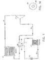
FIG.1 is a schematic diagram of one embodiment of a vapor compression heat transfer system including an intermediate heat exchanger, used to practice the method of exchanging heat in a vapor compression heat transfer system according to the present invention. -
FIG. 1A is a cross-sectional view of a particular embodiment of an intermediate heat exchanger where the tubes of the heat exchanger are concentric with each other. -
FIG. 2 is a perspective view of a dual-row condenser which can be used with the vapor compression heat transfer system ofFIG. 1 . -
FIG. 3 is a perspective view of a dual-row evaporator used which can be used with the vapor compression heat transfer system ofFIG. 1 . - The present invention provides a method of exchanging heat in a vapor compression heat transfer system. A vapor-compression heat transfer system is a closed loop system which re-uses working fluid in multiple steps producing a cooling effect in one step and a heating effect in a different step. Such a system generally includes an evaporator, a compressor, a condenser and an expansion device, and is known in the art. Reference will be made to
Fig. 1 in describing this method. - With reference to
Fig. 1 , liquid working fluid from acondenser 41 flows through a line to an intermediate heat exchanger, or simply IHX. The intermediate heat exchanger includes afirst tube 30, which contains a relatively hot liquid working fluid, and asecond tube 50, which contains a relatively colder gaseous working fluid. The first tube of the IHX is connected to the outlet line of the condenser. The liquid working fluid then flows through anexpansion device 52 and through aline 62 to anevaporator 42, which is located in the vicinity of a body to cooled. In the evaporator, the working fluid is evaporated, which converts it into a gaseous working fluid, and the vaporization of the working fluid provides cooling. Theexpansion device 52 may be an expansion valve, a capillary tube, an orifice tube or any other device where the working fluid may undergo an abrupt reduction in pressure. The evaporator has an outlet, through which the cold gaseous working fluid flows to thesecond tube 50 of the IHX, wherein the cold gaseous working fluid comes in thermal contact with the hot liquid working fluid in thefirst tube 30 of the IHX, and thus the cold gaseous working fluid is warmed somewhat. The gaseous working fluid flows from the second tube of the IHX through aline 63 to the inlet of acompressor 12. The gas is compressed in the compressor, and the compressed gaseous working fluid is discharged from the compressor and flows to thecondenser 41 through aline 61 wherein the working fluid is condensed, thus giving off heat, and the cycle then repeats. - In an intermediate heat exchanger, the first tube containing the relatively hotter liquid working fluid and the second tube containing the relatively colder gaseous working fluid are in thermal contact, thus allowing transfer of heat from the hot liquid to the cold gas. The means by which the two tubes are in thermal contact may vary. In one embodiment, the first tube has a larger diameter than the second tube, and the second tube is disposed concentrically in the first tube, and a hot liquid in the first tube surrounds a cold gas in the second tube. This embodiment is shown in
FIG. 1A , where the first tube (30a) surrounds the second tube (50a). - Also, in one embodiment, the working fluid in the second tube of the internal heat exchanger may flow in a countercurrent direction to the direction of flow of the working fluid in the first tube, thereby cooling the working fluid in the first tube and heating the working fluid in the second tube.
- Cross-current/counter-current heat exchange is provided in the system of
Fig. 1 by a dual-row condenser or a dual-row evaporator. Such condensers and evaporators are described in detail inU.S. Provisional Patent Application No. 60/875,982, filed December 19, 2006 PCT/US07/25675, filed December 17, 2007 ), and may be designed particularly for working fluids that comprise non-azeotropic or near-azeotropic compositions. Therefore, in accordance with the present invention, there is provided a vapor compression heat transfer system which comprises either a dual-row condenser, or a dual-row evaporator, or both. Such a system is the same as that described above with respect toFIG. 1 , except for the description of the dual-row condenser or the dual-row evaporator. - Reference will be made to
FIG. 2 to describe such a system which includes a dual-row condenser. A dual-row condenser is shown at 41 inFIG. 2 . In this dual-row cross-current/counter-current design, a hot working fluid enters the condenser through a first, or back,row 14, passes through the first row, and exits the condenser through a second, or front,row 13. The first row is connected to an inlet, or collector, 6, so that the working fluid entersfirst row 14 via collector, 6. The first row comprises a first inlet manifold and a plurality of channels, or passes, one of which is shown at 2 inFig. 2 . The working fluid enters the inlet and flows insidefirst pass 2 of the first row. The channels allow the working fluid at a first temperature to flow into the manifold and then through the channels in at least one direction and collect in a second outlet manifold, which is shown at 15 inFig. 2 .In the first, or back, row the working fluid is cooled in a counter current manner by air, which has been heated by the second, orfront row 13 of this dual-row condenser. The working fluid flows fromfirst pass 2 of thefirst row 14, to a second row, 13 which is connected to the first row. The second row comprises a plurality of channels for conducting the working fluid at a second temperature less than the working in the first row. The working fluid flows fromfirst pass 2 of the first row to apass 3 of the second by a conduit, orconnection 7 and by aconduit 16. The working fluid then flows frompass 3 to apass 4 insecond row 13 through a conduit, orconnection 8, which connects the first and second rows. The working fluid then flows frompass 4 to apass 5 through a conduit, orconnection 9. Then the sub-cooled working fluid exits the condenser throughoutlet manifold 15 by a connection, or outlet, 10. Air is circulated in a counter-current manner relative to the working fluid flow, as indicated by thearrow having points FIG. 2 . The design shown inFIG. 2 is generic and can be used for any air-to-refrigerant condenser in stationary applications as well as in mobile applications. - Reference will now be made to
FIG. 3 in describing a vapor compression heat transfer system comprising a dual-row evaporator. A dual-row evaporator is shown at 42 inFIG. 3 . In this dual-row cross-current/counter-current design, the dual-row evaporator includes an inlet, a first, or front,row 17 connected to the inlet, a second second, orback row 18, connected to the first row, and an outlet connected to the back row. In particular, the working fluid enters the evaporator 19 at the lowest temperature through an inlet, or collector, 24 as shown inFIG. 3 . Then the working fluid flows downwards through atank 20 to atank 21 through acollector 25, then fromtank 21 to atank 22 in the back row through acollector 26. The working fluid then flows fromtank 22 to atank 23 through acollector 27, and finally exits the evaporator through an outlet, or collector, 28. Air is circulated in a cross-countercurrent arrangement as indicated by thearrow having points FIG. 3 . - In the embodiments as shown in
FIGS. 1, 1A ,2 and 3 , the connecting lines between the components of the vapor compression heat transfer system, through which the working fluid may flow, may be constructed of any typical conduit material known for such purpose. In one embodiment, metal piping or metal tubing (such as aluminum or copper or copper alloy tubing) may be used to connect the components of the heat transfer system. In another embodiment, hoses, constructed of various materials, such as polymers or elastomers, or combinations of such materials with reinforcing materials such as metal mesh etc, may be used in the system. One example of a hose design for heat transfer systems, in particular for automobile air conditioning systems, is provided inU.S. Provisional Patent Application No. 60/841,713, filed September 1, 2006 PCT/US07/019205 filed August 31, 2007 and published asWO2008-027255A1 on March 6, 2008 ). For the tubes of the IHX, metal piping or tubing provides more efficient transfer of heat from the hot liquid working fluid to the cold gaseous working fluid. - Various types of compressors may be used in the vapor compression heat transfer system of the embodiments of the present invention, including reciprocating, rotary, jet, centrifugal, scroll, screw or axial-flow, depending on the mechanical means to compress the fluid, or as positive-displacement (e.g., reciprocating, scroll or screw) or dynamic (e.g., centrifugal or jet).
- The closed loop vapor compression heat transfer system as described herein may be used in stationary refrigeration, air-conditioning, and heat pumps or mobile air-conditioning and refrigeration systems. Stationary air-conditioning and heat pump applications include window, ductless, ducted, packaged terminal, chillers and light commercial and commercial air-conditioning systems, including packaged rooftop. Refrigeration applications include domestic or home refrigerators and freezers, ice machines, self-contained coolers and freezers, walk-in coolers and freezers and supermarket systems, and transport refrigeration systems.
- Mobile refrigeration or mobile air-conditioning systems refer to any refrigeration or air-conditioning system incorporated into a transportation unit for the road, rail, sea or air. In addition, apparatus, which are meant to provide refrigeration or air-conditioning for a system independent of any moving carrier, known as "intermodal" systems, are included in the present invention. Such intermodal systems include "containers" (combined sea/land transport) as well as "swap bodies" (combined road and rail transport). The present invention is particularly useful for road transport refrigerating or air-conditioning apparatus, such as automobile air-conditioning apparatus or refrigerated road transport equipment.
- The working fluid utilized in the vapor compression heat transfer system comprises HFC-1234yf.
- In some embodiments, the working fluid may further comprise at least one compound selected from hydrofluorocarbons, fluoroethers, hydrocarbons, dimethyl ether (DME), carbon dioxide (CO2), ammonia (NH3), and iodotrifluoromethane (CF3I).
- In some embodiments, the working fluid may further comprise hydrofluorocarbons comprising at least one saturated compound containing carbon, hydrogen, and fluorine. Of particular utility are hydrofluorocarbons having 1 to 7 carbon atoms and having a normal boiling point of from about -90°C to about 80°C. Hydrofluorocarbons are commercial products available from a number of sources or may be prepared by methods known in the art. Representative hydrofluorocarbon compounds include but are not limited to fluoromethane (CH3F, HFC-41), difluoromethane (CH2F2, HFC-32), trifluoromethane (CHF3, HFC-23), pentafluoroethane (CF3CHF2, HFC-125), 1,1,2,2-tetrafluoroethane (CHF2CHF2, HFC-134), 1,1,1,2-tetrafluoroethane (CF3CH2F, HFC-134a), 1,1,1-trifluoroethane (CF3CH3, HFC-143a), 1,1-difluoroethane (CHF2CH3, HFC-152a), fluoroethane (CH3CH2F, HFC-161), 1,1,1,2,2,3,3-heptafluoropropane (CF3CF2CHF2, HFC-227ca), 1,1,1,2,3,3,3-heptafluoropropane (CF3CHFCF3, HFC-227ea), 1,1,2,2,3,3,-hexafluoropropane (CHF2CF2CHF2, HFC-236ca), 1,1,1,2,2,3-hexafluoropropane (CF3CF3CH2F, HFC-236cb), 1,1,1,2,3,3-hexafluoropropane (CF3CHFCHF2, HFC-236ea), 1,1,1,3,3,3-hexafluoropropane (CF3CH2CF3, HFC-236fa), 1,1,2,2,3-pentafluoropropane (CHF2CF2CH2F, HFC-245ca), 1,1,1,2,2-pentafluoropropane (CF3CF2CH3, HFC-245cb), 1,1,2,3,3-pentafluoropropane (CHF2CHFCHF2, HFC-245ea), 1,1,1,2,3-pentafluoropropane (CF3CHFCH2F, HFC-245eb), 1,1,1,3,3-pentafluoropropane (CF3CH2CHF2, HFC-245fa), 1,2,2,3-tetrafluoropropane (CH2FCF2CH2F, HFC-254ca), 1,1,2,2-tetrafluoropropane (CHF2CF2CH3, HFC-254cb), 1,1,2,3-tetrafluoropropane (CHF2CHFCH2F, HFC-254ea), 1,1,1,2-tetrafluoropropane (CF3CHFCH3, HFC-254eb), 1,1,3,3-tetrafluoropropane (CHF2CH2CHF2, HFC-254fa), 1,1,1,3-tetrafluoropropane (CF3CH2CH2F, HFC-254fb), 1,1,1-trifluoropropane (CF3CH2CH3, HFC-263fb), 2,2-difluoropropane (CH3CF2CH3, HFC-272ca), 1,2-difluoropropane (CH2FCHFCH3, HFC-272ea), 1,3-difluoropropane (CH2FCH2CH2F, HFC-272fa), 1,1-difluoropropane (CHF2CH2CH3, HFC-272fb), 2-fluoropropane (CH3CHFCH3, HFC-281ea), 1-fluoropropane (CH2FCH2CH3, HFC-281fa), 1,1,2,2,3,3,4,4-octafluorobutane (CHF2CF2CF2CHF2, HFC-338pcc), 1,1,1,2,2,4,4,4-octafluorobutane (CF3CH2CF2CF3, HFC-338mf), 1,1,1,3,3-pentafluorobutane (CF3CH2CHF2, HFC-365mfc), 1,1,1,2,3,4,4,5,5,5-decafluoropentane (CF3CHFCHFCF2CF3, HFC-43-10mee), and 1,1,1,2,2,3,4,5,5,6,6,7,7,7 -tetradecafluoroheptane (CF3CF2CHFCHFCF2CF2CF3, HFC-63-14mee).
- In some embodiments, working fluids may further comprise fluoroethers comprising at least one compound having carbon, fluorine, oxygen and optionally hydrogen, chlorine, bromine or iodine. Fluoroethers are commercially available or may be produced by methods known in the art. Representative fluoroethers include but are not limited to nonafluoromethoxybutane (C4F9OCH3, any or all possible isomers or mixtures thereof); nonafluoroethoxybutane (C4F9OC2H5, any or all possible isomers or mixtures thereof); 2-difluoromethoxy-1,1,1,2-tetrafluoroethane (HFOC-236eaEβγ, or CHF2OCHFCF3); 1,1-difluoro-2-methoxyethane (HFOC-272fbEβγ,CH3OCH2CHF2); 1,1,1,3,3,3-hexafluoro-2-(fluoromethoxy)propane (HFOC-347mmzEβγ, or CH2FOCH(CF3)2); 1,1,1,3,3,3-hexafluoro-2-methoxypropane (HFOC-356mmzEβγ, or CH3OCH(CH3)2); 1,1,1,2,2-pentafluoro-3-methoxypropane (HFOC-365mcEγδ, or CF3CF2CH2OCH3); 2-ethoxy-1,1,1,2,3,3,3-heptafluoropropane (HFOC-467mmyEβγ, or CH3CH2OCF(CF3)2; and mixtures thereof.
- In some embodiments, working fluids may further comprise hydrocarbons comprising compounds having only carbon and hydrogen. Of particular utility are compounds having 3 to 7 carbon atoms. Hydrocarbons are commercially available through numerous chemical suppliers. Representative hydrocarbons include but are not limited to propane, n-butane, isobutane, cyclobutane, n-pentane, 2-methylbutane, 2,2-dimethylpropane, cyclopentane, n-hexane, 2-methylpentane, 2,2-dimethylbutane, 2,3-dimethylbutane, 3-methylpentane, cyclohexane, n-heptane, and cycloheptane.
- In some embodiments, the working fluid may comprise hydrocarbons containing heteroatoms, such as dimethylether (DME, CH3OCH3). DME is commercially available.
- In some embodiments, working fluids may further comprise carbon dioxide (CO2), which is commercially available from various sources or may be prepared by methods known in the art.
- In some embodiments, working fluids may further comprise ammonia (NH3), which is commercially available from various sources or may be prepared by methods known in the art.
- In some embodiments, the working fluid further comprises at least one compound selected from hydrofluorocarbons, fluoroethers, hydrocarbons, dimethyl ether (DME), carbon dioxide (CO2), ammonia (NH3), and iodotrifluoromethane (CF3I).
- In yet another embodiment, the working fluid further comprises at least one compound from the group consisting of HFC-134a, HFC-32, HFC-125, HFC-152a, and CF3I.
- Automobile air conditioning systems with and without an intermediate heat exchanger were tested to determine if an improvement is seen with the IHX. The working fluid was a blend of 95% by weight HFC-1225ye and 5% by weight of HFC-32. Each system had a condenser, evaporator, compressor and a thermal expansion device. The ambient air temperature was 30 °C at the evaporator and the condenser inlets. Tests were performed for 2 compressor speeds, 1000 and 2000 rpm, and for 3 vehicle speeds: 25, 30, and 36 km/h. The volumetric flow rate of air on the evaporator was 380 m3/h.
- The cooling capacity for the system with an IHX shows an increase of 4 to 7% as compared to the system with no IHX. The COP also showed an increase of 2.5 to 4% for the system with the IHX as compared to a system with no IHX.
- Cooling performance is calculated for HFC-134a and HFC-1234yf both with and without an IHX. The conditions used are as follows:
Condenser temperature 55 ° C Evaporator temperature 5 ° C Superheat (absolute) 15 ° C TABLE 5 Test Subcool, ° C COP Capacity kJ/m3 Compressor work, kJ/kg HFC-134a, without IHX 0 4.74 2250.86 29.6 HFC-134a, with IHX 5.0 5.02 2381.34 29.6 HFC-134a, % increase with IHX 5.91 5.80 HFC-1234yf, without IHX 0 4.64 2172.43 24.37 HFC-1234yf with IHX 5.8 5.00 2335.38 24.37 HFC-1234yf, % increase with IHX 7.76 7.50 - The data above demonstrate an unexpected level of improvement in energy efficiency (COP) and cooling capacity for the fluoroolefin (HFC-1234yf) with the IHX, as compared to that gained by HFC-134a with the IHX. In particular, COP was increased by 7.67% and cooling capacity increased by 7.50%.
- It should be noted that the subcooling difference arises from the differences in molecular weight, liquid density and liquid heat capacity for HFC-1234yf as compared to HFC-134a. Based on these parameters it was estimated that there would be a difference in subcoolingachieved with the different compounds. When the HFC-134a subcool was set to 5 ° C, the corresponding subcooling for HFC-1234yf was calculated to be 5.8 ° C.
Claims (5)
- A method for exchanging heat in a vapor compression heat transfer system having a working fluid circulating therethrough, comprising the steps of:(a) circulating a working fluid comprising a fluoroolefin to an inlet of a first tube of an internal heat exchanger (30), through the internal heat exchanger and to an outlet thereof;(b) circulating the working fluid from the outlet of the first tube of the internal heat exchanger to an inlet of an evaporator (42), through the evaporator to evaporate the working fluid, thereby convert it into a gaseous working fluid, and through an outlet of the evaporator;(c) circulating the working fluid from the outlet of the evaporator to an inlet of a second tube of the internal heat exchanger (50) to transfer heat from the liquid working fluid from the condenser (41) to the gaseous working fluid from the evaporator, through the internal heat exchanger, and to an outlet of the second tube;(d) circulating the working fluid from the outlet of the second tube of the internal heat exchanger to an inlet of compressor (12), through the compressor to compress the gaseous working fluid, and to an outlet of the compressor;(e) circulating the working fluid from the outlet of the compressor to an inlet of a condenser (41) and through the condenser to condense the compressed gaseous working fluid into a liquid, and to an outlet of the condenser;(f) circulating the working fluid from the outlet of the condenser to an inlet of the first tube of the internal heat exchanger (30) to transfer heat from the liquid from the condenser to the gas from the evaporator, and to an outlet of the first tube; and(g) circulating the working fluid from the outlet of the first tube of the internal heat exchanger back to the evaporator (42);characterized in that the working fluid comprises HFC-1234yf,
and wherein the condensing step comprises:(i) circulating the working fluid to a back row (14) of a dual- row condenser (41), where the back row receives the working fluid at a first temperature, and(ii) circulating the working fluid to a front row (13) of the dual- row condenser, wherethe front row receives the working fluid at a second temperature, where the second temperature is less than the first temperature, so that air which travels across the front row and the back row is preheated, whereby the temperature of the air is greater when it reaches the back row than when it reaches the front row; and /orwherein the evaporating step comprises:(i) passing the working fluid through an inlet of a dual-row evaporator (42) having a first row and a second row,(ii) circulating the working fluid in the first row (17) J Z in a direction perpendicular to the flow of fluid through the inlet of the evaporator, and(iii)circulating the working fluid in the second row (18) in a direction generally counter to the direction of the flow of the working fluid through the inlet. - The method of claim 1, where the working fluid in the second tube of the internal heat exchanger (50) flows in a countercurrent direction to the direction of flow of the working fluid in the first tube of the internal heat exchanger (30), thereby cooling the working fluid in the first tube and heating the working fluid in the second tube.
- The method of claim 1, where the first tube of the internal heat exchanger (30) has a larger diameter than the second tube of the internal heat exchanger (50), and the second tube is disposed concentrically in the first tube, and a hot liquid in the first tube surrounds a cool gas in the second tube.
- The method of claim 1, wherein the working fluid further comprises at least one compound selected from hydrofluorocarbons, fluoroethers, hydrocarbons, dimethyl ether (DME), carbon dioxide (CO2), ammonia (NH3), and iodotrifluoromethane (CF3I).
- A heat transfer system comprising a working fluid, an internal heat exchanger, an evaporator, a compressor and a condenser, wherein:the internal heat exchanger has a first tube (30) having an inlet and an outlet and a second tube (50) having an inlet and an outlet;the evaporator(42) has an inlet and an outlet wherein the inlet of the evaporator is connected to the outlet of the first tube of the internal heat exchanger and the outlet of the evaporator is connected to the inlet of the second tube of the internal heat exchanger;the compressor (12) has an inlet and an outlet wherein the inlet of the compressor is connected to the outlet of the second tube of the internal heat exchanger and the outlet of the compressor is connected to the condenser;the condenser (41) has an inlet and an outlet wherein the inlet of the condenser is connected to the outlet of the compressor and the outlet of the condenser is connected to the inlet of the first tube of the internal heat exchanger;characterized in that the working fluid comprises HFC-1234yf, and whereinthe condenser is a dual-row condenser having: (i) an inlet, (ii) a first row (14) connected to the inlet, the first row comprising a first inlet manifold and a plurality of channels for allowing a working fluid at a first temperature to flow into the manifold and then through the channels in at least one direction and collect in a second outlet manifold, (iii) a second row (13) connected to the first row, the second row comprising a plurality of channels for conducting a working fluid at a second temperature less than the working fluid in the first row, and (iv) a conduit connecting the first row to the second row;and/or the evaporator is a dual-row evaporator for evaporating a working fluid, the evaporator having: (i) an inlet, (ii) a front row (17) connected to the inlet; (iii) a back row (18) connected to the front row, and (iv) an outlet connected to the back row.
Priority Applications (2)
| Application Number | Priority Date | Filing Date | Title |
|---|---|---|---|
| EP24158471.3A EP4349694A2 (en) | 2007-01-31 | 2008-05-09 | A vapor compression heat transfer system |
| EP22209806.3A EP4160127B1 (en) | 2007-01-31 | 2008-05-09 | A vapor compression heat transfer system |
Applications Claiming Priority (5)
| Application Number | Priority Date | Filing Date | Title |
|---|---|---|---|
| US92882607P | 2007-05-11 | 2007-05-11 | |
| US98856207P | 2007-11-16 | 2007-11-16 | |
| PCT/US2007/025675 WO2008085314A2 (en) | 2006-12-19 | 2007-12-17 | Dual row heat exchanger and automobile bumper incorporating the same |
| PCT/US2008/006043 WO2008140809A2 (en) | 2007-05-11 | 2008-05-09 | Method for exchanging heat in a vapor compression heat transfer system and a vapor compression heat transfer system comprising an intermediate heat exchanger with a dual-row evaporator or condenser |
| EP08767666.4A EP2145150B8 (en) | 2007-05-11 | 2008-05-09 | Method for exchanging heat in a vapor compression heat transfer system and a vapor compression heat transfer system comprising an intermediate heat exchanger with a dual-row evaporator or condenser |
Related Parent Applications (2)
| Application Number | Title | Priority Date | Filing Date |
|---|---|---|---|
| EP08767666.4A Division-Into EP2145150B8 (en) | 2007-01-31 | 2008-05-09 | Method for exchanging heat in a vapor compression heat transfer system and a vapor compression heat transfer system comprising an intermediate heat exchanger with a dual-row evaporator or condenser |
| EP08767666.4A Division EP2145150B8 (en) | 2007-01-31 | 2008-05-09 | Method for exchanging heat in a vapor compression heat transfer system and a vapor compression heat transfer system comprising an intermediate heat exchanger with a dual-row evaporator or condenser |
Related Child Applications (2)
| Application Number | Title | Priority Date | Filing Date |
|---|---|---|---|
| EP24158471.3A Division EP4349694A2 (en) | 2007-01-31 | 2008-05-09 | A vapor compression heat transfer system |
| EP22209806.3A Division EP4160127B1 (en) | 2007-01-31 | 2008-05-09 | A vapor compression heat transfer system |
Publications (2)
| Publication Number | Publication Date |
|---|---|
| EP3091320A1 EP3091320A1 (en) | 2016-11-09 |
| EP3091320B1 true EP3091320B1 (en) | 2022-11-30 |
Family
ID=39870623
Family Applications (4)
| Application Number | Title | Priority Date | Filing Date |
|---|---|---|---|
| EP16164723.5A Active EP3091320B1 (en) | 2007-01-31 | 2008-05-09 | A vapor compression heat transfer system |
| EP22209806.3A Active EP4160127B1 (en) | 2007-01-31 | 2008-05-09 | A vapor compression heat transfer system |
| EP08767666.4A Revoked EP2145150B8 (en) | 2007-01-31 | 2008-05-09 | Method for exchanging heat in a vapor compression heat transfer system and a vapor compression heat transfer system comprising an intermediate heat exchanger with a dual-row evaporator or condenser |
| EP24158471.3A Pending EP4349694A2 (en) | 2007-01-31 | 2008-05-09 | A vapor compression heat transfer system |
Family Applications After (3)
| Application Number | Title | Priority Date | Filing Date |
|---|---|---|---|
| EP22209806.3A Active EP4160127B1 (en) | 2007-01-31 | 2008-05-09 | A vapor compression heat transfer system |
| EP08767666.4A Revoked EP2145150B8 (en) | 2007-01-31 | 2008-05-09 | Method for exchanging heat in a vapor compression heat transfer system and a vapor compression heat transfer system comprising an intermediate heat exchanger with a dual-row evaporator or condenser |
| EP24158471.3A Pending EP4349694A2 (en) | 2007-01-31 | 2008-05-09 | A vapor compression heat transfer system |
Country Status (11)
| Country | Link |
|---|---|
| US (5) | US20090120619A1 (en) |
| EP (4) | EP3091320B1 (en) |
| JP (1) | JP2010526982A (en) |
| KR (1) | KR101513319B1 (en) |
| CN (2) | CN101680691A (en) |
| AR (1) | AR066522A1 (en) |
| BR (1) | BRPI0810282A2 (en) |
| CA (3) | CA3002834C (en) |
| ES (2) | ES2935119T3 (en) |
| MX (1) | MX345550B (en) |
| WO (1) | WO2008140809A2 (en) |
Families Citing this family (62)
| Publication number | Priority date | Publication date | Assignee | Title |
|---|---|---|---|---|
| US7700004B2 (en) * | 2005-11-01 | 2010-04-20 | E.I. Du Pont De Nemours And Company | Solvent compositions comprising unsaturated fluorinated hydrocarbons |
| DE102006004870A1 (en) * | 2006-02-02 | 2007-08-16 | Siltronic Ag | Semiconductor layer structure and method for producing a semiconductor layer structure |
| EP2530140B1 (en) | 2006-02-28 | 2017-09-27 | The Chemours Company FC, LLC | Azeotropic compositions comprising fluorinated compounds for cleaning applications |
| US8974688B2 (en) * | 2009-07-29 | 2015-03-10 | Honeywell International Inc. | Compositions and methods for refrigeration |
| EP3091320B1 (en) | 2007-05-11 | 2022-11-30 | The Chemours Company FC, LLC | A vapor compression heat transfer system |
| US7641808B2 (en) | 2007-08-23 | 2010-01-05 | E.I. Du Pont De Nemours And Company | Azeotropic compositions comprising fluorinated olefins for cleaning applications |
| US8333901B2 (en) | 2007-10-12 | 2012-12-18 | Mexichem Amanco Holding S.A. De C.V. | Heat transfer compositions |
| US8628681B2 (en) | 2007-10-12 | 2014-01-14 | Mexichem Amanco Holding S.A. De C.V. | Heat transfer compositions |
| US8512591B2 (en) | 2007-10-12 | 2013-08-20 | Mexichem Amanco Holding S.A. De C.V. | Heat transfer compositions |
| GB201002625D0 (en) | 2010-02-16 | 2010-03-31 | Ineos Fluor Holdings Ltd | Heat transfer compositions |
| JP2009257652A (en) | 2008-02-29 | 2009-11-05 | Daikin Ind Ltd | Refrigerating apparatus |
| FR2936806B1 (en) | 2008-10-08 | 2012-08-31 | Arkema France | REFRIGERANT FLUID |
| FR2942237B1 (en) * | 2009-02-13 | 2013-01-04 | Arkema France | METHOD FOR HEATING AND / OR AIR CONDITIONING A VEHICLE |
| CA2752263A1 (en) * | 2009-03-06 | 2010-09-10 | Solvay Fluor Gmbh | Use of unsaturated hydrofluorocarbons |
| JP5386201B2 (en) * | 2009-03-12 | 2014-01-15 | 三菱重工業株式会社 | Heat pump equipment |
| JP2010255906A (en) * | 2009-04-23 | 2010-11-11 | Sanden Corp | Refrigerating cycle |
| GB0915004D0 (en) * | 2009-08-28 | 2009-09-30 | Ineos Fluor Holdings Ltd | Heat transfer composition |
| US9074115B2 (en) * | 2009-08-28 | 2015-07-07 | Mexichem Amanco Holding S.A. De C.V. | Heat transfer compositions |
| FR2950066B1 (en) | 2009-09-11 | 2011-10-28 | Arkema France | LOW AND MEDIUM TEMPERATURE REFRIGERATION |
| FR2950070B1 (en) | 2009-09-11 | 2011-10-28 | Arkema France | TERNARY COMPOSITIONS FOR HIGH CAPACITY REFRIGERATION |
| FR2950065B1 (en) * | 2009-09-11 | 2012-02-03 | Arkema France | BINARY REFRIGERANT FLUID |
| FR2950069B1 (en) * | 2009-09-11 | 2011-11-25 | Arkema France | USE OF TERNARY COMPOSITIONS |
| FR2950068B1 (en) | 2009-09-11 | 2012-05-18 | Arkema France | HEAT TRANSFER METHOD |
| US10035938B2 (en) | 2009-09-11 | 2018-07-31 | Arkema France | Heat transfer fluid replacing R-134a |
| FR2950071B1 (en) * | 2009-09-11 | 2012-02-03 | Arkema France | TERNARY COMPOSITIONS FOR LOW CAPACITY REFRIGERATION |
| WO2011034904A1 (en) * | 2009-09-16 | 2011-03-24 | E. I. Du Pont De Nemours And Company | Chiller apparatus containing trans-1,1,1,4,4,4-hexafluoro-2-butene and methods of producing cooling therein |
| EP2591296A2 (en) * | 2009-11-03 | 2013-05-15 | E. I. du Pont de Nemours and Company | Cascade refrigeration system with fluoroolefin refrigerant |
| CN102712838A (en) | 2009-12-21 | 2012-10-03 | 纳幕尔杜邦公司 | Compositions comprising tetrafluoropropene and difluoromethane and uses thereof |
| GB201002622D0 (en) | 2010-02-16 | 2010-03-31 | Ineos Fluor Holdings Ltd | Heat transfer compositions |
| GB201002619D0 (en) * | 2010-02-16 | 2010-03-31 | Ineos Fluor Holdings Ltd | Heat transfer compositions |
| FR2957083B1 (en) * | 2010-03-02 | 2015-12-11 | Arkema France | HEAT TRANSFER FLUID FOR CENTRIFUGAL COMPRESSOR |
| KR20130051943A (en) | 2010-04-16 | 2013-05-21 | 이 아이 듀폰 디 네모아 앤드 캄파니 | Composition comprising 2,3,3,3-tetrafluoropropene and 1,1,1,2-tetrafluoroethane, chillers containing same and methods of producing cooling therein |
| FR2959999B1 (en) | 2010-05-11 | 2012-07-20 | Arkema France | HEAT TRANSFER FLUIDS AND THEIR USE IN COUNTER-CURRENT HEAT EXCHANGERS |
| FR2959997B1 (en) | 2010-05-11 | 2012-06-08 | Arkema France | HEAT TRANSFER FLUIDS AND THEIR USE IN COUNTER-CURRENT HEAT EXCHANGERS |
| CN102939350A (en) | 2010-05-20 | 2013-02-20 | 墨西哥化学阿玛科股份有限公司 | Heat transfer compositions |
| PL2571952T3 (en) | 2010-05-20 | 2016-01-29 | Mexichem Fluor Sa De Cv | Heat transfer compositions |
| GB2481443B (en) | 2010-06-25 | 2012-10-17 | Mexichem Amanco Holding Sa | Heat transfer compositions |
| FR2964977B1 (en) | 2010-09-20 | 2013-11-01 | Arkema France | COMPOSITION BASED ON 3,3,3-TETRAFLUOROPROPENE |
| WO2012053157A1 (en) * | 2010-10-22 | 2012-04-26 | 株式会社ヴァレオジャパン | Refrigeration cycle and condenser with supercooling unit |
| US20120119136A1 (en) * | 2010-11-12 | 2012-05-17 | Honeywell International Inc. | Low gwp heat transfer compositions |
| FR2976289B1 (en) * | 2011-06-07 | 2013-05-24 | Arkema France | BINARY COMPOSITIONS OF 1,3,3,3-TETRAFLUOROPROPENE AND AMMONIA |
| US20130104575A1 (en) * | 2011-11-02 | 2013-05-02 | E I Du Pont De Nemours And Company | Use of compositions comprising 1,1,1,2,3-pentafluoropropane and optionally z-1,1,1,4,4,4-hexafluoro-2-butene in high temperature heat pumps |
| US20130333402A1 (en) * | 2012-06-18 | 2013-12-19 | GM Global Technology Operations LLC | Climate control systems for motor vehicles and methods of operating the same |
| US20140116083A1 (en) * | 2012-10-29 | 2014-05-01 | Myungjin Chung | Refrigerator |
| EP2970735A4 (en) * | 2013-03-15 | 2016-11-23 | Honeywell Int Inc | Heat transfer compositions and methods |
| CN105473955B (en) | 2013-10-25 | 2017-12-08 | 三菱重工制冷空调系统株式会社 | Coolant circulating device, refrigerant circulation method and sour suppressing method |
| JP6381890B2 (en) * | 2013-10-25 | 2018-08-29 | 三菱重工サーマルシステムズ株式会社 | Refrigerant circulation device, refrigerant circulation method, and isomerization suppression method |
| EP3572758B1 (en) | 2014-02-21 | 2023-04-05 | Rolls-Royce Corporation | Microchannel heat exchangers for gas turbine intercooling and condensing |
| US10330364B2 (en) | 2014-06-26 | 2019-06-25 | Hudson Technologies, Inc. | System and method for retrofitting a refrigeration system from HCFC to HFC refrigerant |
| US20170333941A1 (en) * | 2014-10-28 | 2017-11-23 | President And Fellows Of Harvard College | High energy efficiency phase change device using convex surface features |
| CN105820799A (en) * | 2015-01-05 | 2016-08-03 | 浙江省化工研究院有限公司 | Environment-friendly type refrigeration composition containing HFO-1234ze(E) |
| CN107072106A (en) * | 2016-12-28 | 2017-08-18 | 浙江海洋大学 | Unmanned boat circuit system fire prevention heat sink and fire prevention cool-down method |
| WO2019039521A1 (en) * | 2017-08-25 | 2019-02-28 | Agc株式会社 | Solvent composition, cleaning method, method for producing coated substrate, and heat transfer medium |
| WO2019056855A1 (en) * | 2017-09-20 | 2019-03-28 | 杭州三花家电热管理系统有限公司 | Heat exchange assembly, heat exchange system, and indoor heating system |
| WO2019109000A1 (en) * | 2017-11-30 | 2019-06-06 | Honeywell International Inc. | Heat transfer compositions, methods, and systems |
| US11384970B2 (en) * | 2017-12-25 | 2022-07-12 | Mitsubishi Electric Corporation | Heat exchanger and refrigeration cycle apparatus |
| CN110343509B (en) * | 2018-04-02 | 2021-09-14 | 江西天宇化工有限公司 | Non-combustible mixed refrigerant capable of reducing greenhouse effect and application thereof |
| CN110343510B (en) | 2018-04-02 | 2021-06-04 | 江西天宇化工有限公司 | Non-flammable mixed refrigerant with low-temperature chamber effect and application thereof |
| CN109945292B (en) * | 2019-03-18 | 2021-05-25 | 山东大学 | Double-heat-source two-stage compression heat pump hot water system with auxiliary compressor and method |
| JP2022084964A (en) * | 2019-04-03 | 2022-06-08 | ダイキン工業株式会社 | Refrigerant cycle device |
| ES2912000T3 (en) * | 2019-05-21 | 2022-05-24 | Carrier Corp | Refrigeration appliance and its use |
| WO2023069574A1 (en) * | 2021-10-21 | 2023-04-27 | The Chemours Company Fc, Llc | Compositions comprising 2,3,3,3-tetrafluoropropene |
Citations (2)
| Publication number | Priority date | Publication date | Assignee | Title |
|---|---|---|---|---|
| US20040244411A1 (en) * | 2003-05-27 | 2004-12-09 | Nobuo Ichimura | Air-conditioner |
| US20070100175A1 (en) * | 2005-11-01 | 2007-05-03 | Miller Ralph N | Azeotrope compositions comprising 2,3,3,3-tetrafluoropropene and hydrogen fluoride and uses thereof |
Family Cites Families (59)
| Publication number | Priority date | Publication date | Assignee | Title |
|---|---|---|---|---|
| US1507560A (en) | 1921-10-05 | 1924-09-09 | Island | |
| GB230612A (en) | 1924-02-21 | 1925-03-19 | Thomas Edgar Wood | Improvements in and relating to heat transmission apparatus |
| US2120764A (en) * | 1936-09-25 | 1938-06-14 | York Ice Machinery Corp | Refrigeration |
| FR1346189A (en) | 1963-02-01 | 1963-12-13 | Gevaert Photo Prod Nv | Industrial manufacture of ketene |
| GB1084795A (en) | 1963-09-13 | 1967-09-27 | Joseph Kaye & Company Inc | Apparatus for compressing refrigerant vapour |
| GB1027195A (en) | 1963-11-07 | 1966-04-27 | Metallurg Engineers Ltd | Improvements in heat exchangers |
| US3877242A (en) * | 1973-10-11 | 1975-04-15 | Int Refrigeration Engineers | Harvest control unit for an ice-making machine |
| DE2535490C2 (en) | 1975-08-08 | 1982-09-16 | Linde Ag, 6200 Wiesbaden | Refrigeration unit |
| GB1595616A (en) | 1977-01-21 | 1981-08-12 | Hitachi Ltd | Air conditioning system |
| JPS55133167U (en) * | 1979-03-13 | 1980-09-20 | ||
| US4316366A (en) * | 1980-04-21 | 1982-02-23 | Carrier Corporation | Method and apparatus for integrating components of a refrigeration system |
| JPS62255762A (en) | 1986-04-30 | 1987-11-07 | 株式会社日立製作所 | Air conditioner |
| FR2614686A1 (en) | 1987-04-28 | 1988-11-04 | Puicervert Luc | Heat exchanger |
| JPH03279763A (en) * | 1990-03-27 | 1991-12-10 | Showa Alum Corp | Multiple heat exchanger |
| US5529116A (en) | 1989-08-23 | 1996-06-25 | Showa Aluminum Corporation | Duplex heat exchanger |
| JP3030036B2 (en) | 1989-08-23 | 2000-04-10 | 昭和アルミニウム株式会社 | Double heat exchanger |
| JPH05170135A (en) * | 1991-12-18 | 1993-07-09 | Mazda Motor Corp | Front body structure for automobile |
| EP0734368B1 (en) | 1993-12-14 | 2001-08-29 | E.I. Du Pont De Nemours And Company | Process for perhalofluorinated butanes |
| CN1135341C (en) * | 1994-05-30 | 2004-01-21 | 三菱电机株式会社 | Refrigerating circulating system and refrigerating air conditioning device |
| JPH1019418A (en) * | 1996-07-03 | 1998-01-23 | Toshiba Corp | Refrigerator with deep freezer |
| JPH1199964A (en) | 1997-09-29 | 1999-04-13 | Aisin Seiki Co Ltd | Vehicle front end module structure |
| DE19813673B4 (en) * | 1998-03-27 | 2004-01-29 | Daimlerchrysler Ag | Method and device for heating and cooling a useful space of a motor vehicle |
| US6327866B1 (en) | 1998-12-30 | 2001-12-11 | Praxair Technology, Inc. | Food freezing method using a multicomponent refrigerant |
| US6176102B1 (en) * | 1998-12-30 | 2001-01-23 | Praxair Technology, Inc. | Method for providing refrigeration |
| JP2001121941A (en) | 1999-10-28 | 2001-05-08 | Denso Corp | On-vehicle mounting structure of heat exchanger |
| JP2001263831A (en) * | 2000-03-24 | 2001-09-26 | Mitsubishi Electric Corp | Refrigerating cycle system |
| KR100426640B1 (en) * | 2000-09-25 | 2004-04-08 | 주식회사 템피아 | Refrigeration cycle |
| JP2003021432A (en) | 2001-07-09 | 2003-01-24 | Zexel Valeo Climate Control Corp | Condenser |
| US6748759B2 (en) * | 2001-08-02 | 2004-06-15 | Ho-Hsin Wu | High efficiency heat exchanger |
| EP1452814A4 (en) * | 2001-11-08 | 2008-09-10 | Zexel Valeo Climate Contr Corp | Heat exchanger and tube for heat exchanger |
| JP2004011959A (en) * | 2002-06-04 | 2004-01-15 | Sanyo Electric Co Ltd | Supercritical refrigerant cycle equipment |
| EP2277942A3 (en) * | 2002-10-25 | 2014-07-09 | Honeywell International, Incorporated. | Compositions containing fluorine substituted olefins |
| US20040089839A1 (en) * | 2002-10-25 | 2004-05-13 | Honeywell International, Inc. | Fluorinated alkene refrigerant compositions |
| KR100496376B1 (en) * | 2003-03-31 | 2005-06-22 | 한명범 | Improvement system of energy efficiency for use in a refrigeration cycle |
| JP4124136B2 (en) * | 2003-04-21 | 2008-07-23 | 株式会社デンソー | Refrigerant evaporator |
| JP2005037054A (en) * | 2003-07-15 | 2005-02-10 | Sanyo Electric Co Ltd | Heat exchanger for refrigerant cycle device |
| US7592494B2 (en) * | 2003-07-25 | 2009-09-22 | Honeywell International Inc. | Process for the manufacture of 1,3,3,3-tetrafluoropropene |
| JP2005083741A (en) * | 2003-09-05 | 2005-03-31 | Lg Electronics Inc | Air conditioner having heat exchanger and refrigerant switching means |
| GB2405688A (en) | 2003-09-05 | 2005-03-09 | Applied Design & Eng Ltd | Refrigerator |
| US7276177B2 (en) * | 2004-01-14 | 2007-10-02 | E.I. Dupont De Nemours And Company | Hydrofluorocarbon refrigerant compositions and uses thereof |
| DE602005011594D1 (en) * | 2004-04-16 | 2009-01-22 | Honeywell Int Inc | AZEOTROPY TRIFLUOROODMETHANE COMPOSITIONS |
| US7605117B2 (en) * | 2004-04-16 | 2009-10-20 | Honeywell International Inc. | Methods of replacing refrigerant |
| US7629306B2 (en) | 2004-04-29 | 2009-12-08 | Honeywell International Inc. | Compositions comprising tetrafluoropropene and carbon dioxide |
| US7028490B2 (en) * | 2004-05-28 | 2006-04-18 | Ut-Batelle, Llc | Water-heating dehumidifier |
| JP2006183889A (en) * | 2004-12-27 | 2006-07-13 | Nissan Motor Light Truck Co Ltd | Heat pump device |
| US20060243945A1 (en) * | 2005-03-04 | 2006-11-02 | Minor Barbara H | Compositions comprising a fluoroolefin |
| US7569170B2 (en) | 2005-03-04 | 2009-08-04 | E.I. Du Pont De Nemours And Company | Compositions comprising a fluoroolefin |
| US20060243944A1 (en) * | 2005-03-04 | 2006-11-02 | Minor Barbara H | Compositions comprising a fluoroolefin |
| GB0507953D0 (en) * | 2005-04-21 | 2005-05-25 | Thermal Energy Systems Ltd | Heat pump |
| CN1710356A (en) * | 2005-06-21 | 2005-12-21 | 上海本家空调系统有限公司 | Heat-recovery energy-storage type water source heat pump |
| TWI657070B (en) * | 2005-06-24 | 2019-04-21 | 美商哈尼威爾國際公司 | Compositions containing fluorine substituted olefins and uses thereof |
| JP2007032949A (en) * | 2005-07-28 | 2007-02-08 | Showa Denko Kk | Heat exchanger |
| JP4661449B2 (en) * | 2005-08-17 | 2011-03-30 | 株式会社デンソー | Ejector refrigeration cycle |
| JP4840681B2 (en) * | 2005-09-16 | 2011-12-21 | 株式会社ヴァレオジャパン | Heat exchanger |
| US7708903B2 (en) | 2005-11-01 | 2010-05-04 | E.I. Du Pont De Nemours And Company | Compositions comprising fluoroolefins and uses thereof |
| US7617766B2 (en) | 2006-08-25 | 2009-11-17 | Sunbeam Products, Inc. | Baby food maker |
| EP2118229A2 (en) | 2006-09-01 | 2009-11-18 | E.I. Du Pont De Nemours And Company | Method for circulating selected heat transfer fluids through a closed loop cycle |
| WO2008085314A2 (en) | 2006-12-19 | 2008-07-17 | E. I. Du Pont De Nemours And Company | Dual row heat exchanger and automobile bumper incorporating the same |
| EP3091320B1 (en) | 2007-05-11 | 2022-11-30 | The Chemours Company FC, LLC | A vapor compression heat transfer system |
-
2008
- 2008-05-09 EP EP16164723.5A patent/EP3091320B1/en active Active
- 2008-05-09 CN CN200880015513A patent/CN101680691A/en active Pending
- 2008-05-09 BR BRPI0810282A patent/BRPI0810282A2/en not_active IP Right Cessation
- 2008-05-09 CA CA3002834A patent/CA3002834C/en active Active
- 2008-05-09 CA CA2944695A patent/CA2944695C/en active Active
- 2008-05-09 KR KR1020097025754A patent/KR101513319B1/en active IP Right Grant
- 2008-05-09 EP EP22209806.3A patent/EP4160127B1/en active Active
- 2008-05-09 WO PCT/US2008/006043 patent/WO2008140809A2/en active Application Filing
- 2008-05-09 EP EP08767666.4A patent/EP2145150B8/en not_active Revoked
- 2008-05-09 MX MX2009012100A patent/MX345550B/en active IP Right Grant
- 2008-05-09 JP JP2010507484A patent/JP2010526982A/en active Pending
- 2008-05-09 ES ES16164723T patent/ES2935119T3/en active Active
- 2008-05-09 CA CA2682312A patent/CA2682312C/en active Active
- 2008-05-09 AR ARP080101986A patent/AR066522A1/en not_active Application Discontinuation
- 2008-05-09 ES ES08767666.4T patent/ES2575130T3/en active Active
- 2008-05-09 CN CN201510800415.1A patent/CN105333653A/en active Pending
- 2008-05-09 EP EP24158471.3A patent/EP4349694A2/en active Pending
- 2008-05-12 US US12/119,023 patent/US20090120619A1/en not_active Abandoned
-
2011
- 2011-08-11 US US13/207,557 patent/US20110290447A1/en not_active Abandoned
-
2018
- 2018-03-29 US US15/939,644 patent/US11624534B2/en active Active
-
2022
- 2022-12-19 US US18/084,201 patent/US11867436B2/en active Active
-
2023
- 2023-11-17 US US18/512,520 patent/US20240125524A1/en active Pending
Patent Citations (2)
| Publication number | Priority date | Publication date | Assignee | Title |
|---|---|---|---|---|
| US20040244411A1 (en) * | 2003-05-27 | 2004-12-09 | Nobuo Ichimura | Air-conditioner |
| US20070100175A1 (en) * | 2005-11-01 | 2007-05-03 | Miller Ralph N | Azeotrope compositions comprising 2,3,3,3-tetrafluoropropene and hydrogen fluoride and uses thereof |
Also Published As
| Publication number | Publication date |
|---|---|
| CN101680691A (en) | 2010-03-24 |
| CA2944695C (en) | 2018-06-12 |
| US20180231281A1 (en) | 2018-08-16 |
| WO2008140809A2 (en) | 2008-11-20 |
| MX345550B (en) | 2017-02-03 |
| MX2009012100A (en) | 2009-11-23 |
| US20240125524A1 (en) | 2024-04-18 |
| CN105333653A (en) | 2016-02-17 |
| US20230235930A1 (en) | 2023-07-27 |
| ES2575130T3 (en) | 2016-06-24 |
| CA2944695A1 (en) | 2008-11-20 |
| AR066522A1 (en) | 2009-08-26 |
| CA3002834C (en) | 2020-04-07 |
| CA2682312A1 (en) | 2008-11-20 |
| EP2145150B8 (en) | 2016-08-10 |
| US11624534B2 (en) | 2023-04-11 |
| BRPI0810282A2 (en) | 2017-09-26 |
| JP2010526982A (en) | 2010-08-05 |
| US11867436B2 (en) | 2024-01-09 |
| KR101513319B1 (en) | 2015-04-17 |
| US20110290447A1 (en) | 2011-12-01 |
| EP4160127B1 (en) | 2024-02-28 |
| CA2682312C (en) | 2016-11-22 |
| EP2145150A2 (en) | 2010-01-20 |
| CA3002834A1 (en) | 2008-11-20 |
| WO2008140809A3 (en) | 2009-04-30 |
| EP4349694A2 (en) | 2024-04-10 |
| ES2935119T3 (en) | 2023-03-01 |
| KR20100029761A (en) | 2010-03-17 |
| EP2145150B1 (en) | 2016-04-13 |
| US20090120619A1 (en) | 2009-05-14 |
| EP4160127A1 (en) | 2023-04-05 |
| EP3091320A1 (en) | 2016-11-09 |
Similar Documents
| Publication | Publication Date | Title |
|---|---|---|
| EP3091320B1 (en) | A vapor compression heat transfer system | |
| JP5423089B2 (en) | Refrigeration equipment | |
| CN102686957B (en) | Cascade refrigeration system with fluoroolefin refrigerant | |
| US20100012302A1 (en) | Dual row heat exchanger and automobile bumper incorporating the same | |
| US20040123608A1 (en) | Non-azeotropic refrigerant mixture, refrigerating cycle and refrigerating device | |
| JP6418284B1 (en) | Composition containing refrigerant, use thereof, refrigeration method using the same, and refrigerator including the same | |
| CN108700344A (en) | Heat exchange unit | |
| US20220243106A1 (en) | Heat transfer compositions, methods, and systems |
Legal Events
| Date | Code | Title | Description |
|---|---|---|---|
| PUAI | Public reference made under article 153(3) epc to a published international application that has entered the european phase |
Free format text: ORIGINAL CODE: 0009012 |
|
| AC | Divisional application: reference to earlier application |
Ref document number: 2145150 Country of ref document: EP Kind code of ref document: P |
|
| AK | Designated contracting states |
Kind code of ref document: A1 Designated state(s): AT BE BG CH CY CZ DE DK EE ES FI FR GB GR HR HU IE IS IT LI LT LU LV MC MT NL NO PL PT RO SE SI SK TR |
|
| STAA | Information on the status of an ep patent application or granted ep patent |
Free format text: STATUS: THE APPLICATION HAS BEEN PUBLISHED |
|
| STAA | Information on the status of an ep patent application or granted ep patent |
Free format text: STATUS: REQUEST FOR EXAMINATION WAS MADE |
|
| 17P | Request for examination filed |
Effective date: 20170731 |
|
| RBV | Designated contracting states (corrected) |
Designated state(s): AT BE BG CH CY CZ DE DK EE ES FI FR GB GR HR HU IE IS IT LI LT LU LV MC MT NL NO PL PT RO SE SI SK TR |
|
| STAA | Information on the status of an ep patent application or granted ep patent |
Free format text: STATUS: EXAMINATION IS IN PROGRESS |
|
| 17Q | First examination report despatched |
Effective date: 20190306 |
|
| STAA | Information on the status of an ep patent application or granted ep patent |
Free format text: STATUS: EXAMINATION IS IN PROGRESS |
|
| RIC1 | Information provided on ipc code assigned before grant |
Ipc: F28D 21/00 20060101ALN20220425BHEP Ipc: F28D 1/04 20060101ALI20220425BHEP Ipc: F25B 40/00 20060101ALI20220425BHEP Ipc: B62D 25/00 20060101ALI20220425BHEP Ipc: F28D 1/053 20060101AFI20220425BHEP |
|
| RIC1 | Information provided on ipc code assigned before grant |
Ipc: F28D 21/00 20060101ALN20220511BHEP Ipc: F28D 1/04 20060101ALI20220511BHEP Ipc: F25B 40/00 20060101ALI20220511BHEP Ipc: B62D 25/00 20060101ALI20220511BHEP Ipc: F28D 1/053 20060101AFI20220511BHEP |
|
| GRAP | Despatch of communication of intention to grant a patent |
Free format text: ORIGINAL CODE: EPIDOSNIGR1 |
|
| STAA | Information on the status of an ep patent application or granted ep patent |
Free format text: STATUS: GRANT OF PATENT IS INTENDED |
|
| INTG | Intention to grant announced |
Effective date: 20220620 |
|
| GRAS | Grant fee paid |
Free format text: ORIGINAL CODE: EPIDOSNIGR3 |
|
| GRAA | (expected) grant |
Free format text: ORIGINAL CODE: 0009210 |
|
| STAA | Information on the status of an ep patent application or granted ep patent |
Free format text: STATUS: THE PATENT HAS BEEN GRANTED |
|
| AC | Divisional application: reference to earlier application |
Ref document number: 2145150 Country of ref document: EP Kind code of ref document: P |
|
| AK | Designated contracting states |
Kind code of ref document: B1 Designated state(s): AT BE BG CH CY CZ DE DK EE ES FI FR GB GR HR HU IE IS IT LI LT LU LV MC MT NL NO PL PT RO SE SI SK TR |
|
| REG | Reference to a national code |
Ref country code: CH Ref legal event code: EP Ref country code: GB Ref legal event code: FG4D |
|
| REG | Reference to a national code |
Ref country code: AT Ref legal event code: REF Ref document number: 1534969 Country of ref document: AT Kind code of ref document: T Effective date: 20221215 |
|
| REG | Reference to a national code |
Ref country code: IE Ref legal event code: FG4D |
|
| REG | Reference to a national code |
Ref country code: DE Ref legal event code: R096 Ref document number: 602008064671 Country of ref document: DE |
|
| REG | Reference to a national code |
Ref country code: ES Ref legal event code: FG2A Ref document number: 2935119 Country of ref document: ES Kind code of ref document: T3 Effective date: 20230301 |
|
| REG | Reference to a national code |
Ref country code: LT Ref legal event code: MG9D |
|
| REG | Reference to a national code |
Ref country code: NL Ref legal event code: MP Effective date: 20221130 |
|
| PG25 | Lapsed in a contracting state [announced via postgrant information from national office to epo] |
Ref country code: SE Free format text: LAPSE BECAUSE OF FAILURE TO SUBMIT A TRANSLATION OF THE DESCRIPTION OR TO PAY THE FEE WITHIN THE PRESCRIBED TIME-LIMIT Effective date: 20221130 Ref country code: PT Free format text: LAPSE BECAUSE OF FAILURE TO SUBMIT A TRANSLATION OF THE DESCRIPTION OR TO PAY THE FEE WITHIN THE PRESCRIBED TIME-LIMIT Effective date: 20230331 Ref country code: NO Free format text: LAPSE BECAUSE OF FAILURE TO SUBMIT A TRANSLATION OF THE DESCRIPTION OR TO PAY THE FEE WITHIN THE PRESCRIBED TIME-LIMIT Effective date: 20230228 Ref country code: LT Free format text: LAPSE BECAUSE OF FAILURE TO SUBMIT A TRANSLATION OF THE DESCRIPTION OR TO PAY THE FEE WITHIN THE PRESCRIBED TIME-LIMIT Effective date: 20221130 Ref country code: FI Free format text: LAPSE BECAUSE OF FAILURE TO SUBMIT A TRANSLATION OF THE DESCRIPTION OR TO PAY THE FEE WITHIN THE PRESCRIBED TIME-LIMIT Effective date: 20221130 |
|
| REG | Reference to a national code |
Ref country code: AT Ref legal event code: MK05 Ref document number: 1534969 Country of ref document: AT Kind code of ref document: T Effective date: 20221130 |
|
| PG25 | Lapsed in a contracting state [announced via postgrant information from national office to epo] |
Ref country code: PL Free format text: LAPSE BECAUSE OF FAILURE TO SUBMIT A TRANSLATION OF THE DESCRIPTION OR TO PAY THE FEE WITHIN THE PRESCRIBED TIME-LIMIT Effective date: 20221130 Ref country code: LV Free format text: LAPSE BECAUSE OF FAILURE TO SUBMIT A TRANSLATION OF THE DESCRIPTION OR TO PAY THE FEE WITHIN THE PRESCRIBED TIME-LIMIT Effective date: 20221130 Ref country code: IS Free format text: LAPSE BECAUSE OF FAILURE TO SUBMIT A TRANSLATION OF THE DESCRIPTION OR TO PAY THE FEE WITHIN THE PRESCRIBED TIME-LIMIT Effective date: 20230330 Ref country code: HR Free format text: LAPSE BECAUSE OF FAILURE TO SUBMIT A TRANSLATION OF THE DESCRIPTION OR TO PAY THE FEE WITHIN THE PRESCRIBED TIME-LIMIT Effective date: 20221130 Ref country code: GR Free format text: LAPSE BECAUSE OF FAILURE TO SUBMIT A TRANSLATION OF THE DESCRIPTION OR TO PAY THE FEE WITHIN THE PRESCRIBED TIME-LIMIT Effective date: 20230301 |
|
| P01 | Opt-out of the competence of the unified patent court (upc) registered |
Effective date: 20230516 |
|
| PG25 | Lapsed in a contracting state [announced via postgrant information from national office to epo] |
Ref country code: NL Free format text: LAPSE BECAUSE OF FAILURE TO SUBMIT A TRANSLATION OF THE DESCRIPTION OR TO PAY THE FEE WITHIN THE PRESCRIBED TIME-LIMIT Effective date: 20221130 |
|
| PG25 | Lapsed in a contracting state [announced via postgrant information from national office to epo] |
Ref country code: RO Free format text: LAPSE BECAUSE OF FAILURE TO SUBMIT A TRANSLATION OF THE DESCRIPTION OR TO PAY THE FEE WITHIN THE PRESCRIBED TIME-LIMIT Effective date: 20221130 Ref country code: EE Free format text: LAPSE BECAUSE OF FAILURE TO SUBMIT A TRANSLATION OF THE DESCRIPTION OR TO PAY THE FEE WITHIN THE PRESCRIBED TIME-LIMIT Effective date: 20221130 Ref country code: DK Free format text: LAPSE BECAUSE OF FAILURE TO SUBMIT A TRANSLATION OF THE DESCRIPTION OR TO PAY THE FEE WITHIN THE PRESCRIBED TIME-LIMIT Effective date: 20221130 Ref country code: CZ Free format text: LAPSE BECAUSE OF FAILURE TO SUBMIT A TRANSLATION OF THE DESCRIPTION OR TO PAY THE FEE WITHIN THE PRESCRIBED TIME-LIMIT Effective date: 20221130 Ref country code: AT Free format text: LAPSE BECAUSE OF FAILURE TO SUBMIT A TRANSLATION OF THE DESCRIPTION OR TO PAY THE FEE WITHIN THE PRESCRIBED TIME-LIMIT Effective date: 20221130 |
|
| PGFP | Annual fee paid to national office [announced via postgrant information from national office to epo] |
Ref country code: IT Payment date: 20230420 Year of fee payment: 16 Ref country code: FR Payment date: 20230420 Year of fee payment: 16 Ref country code: ES Payment date: 20230601 Year of fee payment: 16 Ref country code: DE Payment date: 20230419 Year of fee payment: 16 |
|
| PG25 | Lapsed in a contracting state [announced via postgrant information from national office to epo] |
Ref country code: SK Free format text: LAPSE BECAUSE OF FAILURE TO SUBMIT A TRANSLATION OF THE DESCRIPTION OR TO PAY THE FEE WITHIN THE PRESCRIBED TIME-LIMIT Effective date: 20221130 |
|
| REG | Reference to a national code |
Ref country code: DE Ref legal event code: R097 Ref document number: 602008064671 Country of ref document: DE |
|
| PLBE | No opposition filed within time limit |
Free format text: ORIGINAL CODE: 0009261 |
|
| STAA | Information on the status of an ep patent application or granted ep patent |
Free format text: STATUS: NO OPPOSITION FILED WITHIN TIME LIMIT |
|
| PGFP | Annual fee paid to national office [announced via postgrant information from national office to epo] |
Ref country code: GB Payment date: 20230420 Year of fee payment: 16 |
|
| 26N | No opposition filed |
Effective date: 20230831 |
|
| PG25 | Lapsed in a contracting state [announced via postgrant information from national office to epo] |
Ref country code: SI Free format text: LAPSE BECAUSE OF FAILURE TO SUBMIT A TRANSLATION OF THE DESCRIPTION OR TO PAY THE FEE WITHIN THE PRESCRIBED TIME-LIMIT Effective date: 20221130 |
|
| REG | Reference to a national code |
Ref country code: CH Ref legal event code: PL |
|
| PG25 | Lapsed in a contracting state [announced via postgrant information from national office to epo] |
Ref country code: MC Free format text: LAPSE BECAUSE OF FAILURE TO SUBMIT A TRANSLATION OF THE DESCRIPTION OR TO PAY THE FEE WITHIN THE PRESCRIBED TIME-LIMIT Effective date: 20221130 |
|
| REG | Reference to a national code |
Ref country code: BE Ref legal event code: MM Effective date: 20230531 |
|
| PG25 | Lapsed in a contracting state [announced via postgrant information from national office to epo] |
Ref country code: MC Free format text: LAPSE BECAUSE OF FAILURE TO SUBMIT A TRANSLATION OF THE DESCRIPTION OR TO PAY THE FEE WITHIN THE PRESCRIBED TIME-LIMIT Effective date: 20221130 Ref country code: LU Free format text: LAPSE BECAUSE OF NON-PAYMENT OF DUE FEES Effective date: 20230509 Ref country code: LI Free format text: LAPSE BECAUSE OF NON-PAYMENT OF DUE FEES Effective date: 20230531 Ref country code: CH Free format text: LAPSE BECAUSE OF NON-PAYMENT OF DUE FEES Effective date: 20230531 |
|
| REG | Reference to a national code |
Ref country code: IE Ref legal event code: MM4A |
|
| PG25 | Lapsed in a contracting state [announced via postgrant information from national office to epo] |
Ref country code: IE Free format text: LAPSE BECAUSE OF NON-PAYMENT OF DUE FEES Effective date: 20230509 |