WO2007111465A1 - Edging process of lens using transparent coating layer for protecting lens - Google Patents
Edging process of lens using transparent coating layer for protecting lens Download PDFInfo
- Publication number
- WO2007111465A1 WO2007111465A1 PCT/KR2007/001491 KR2007001491W WO2007111465A1 WO 2007111465 A1 WO2007111465 A1 WO 2007111465A1 KR 2007001491 W KR2007001491 W KR 2007001491W WO 2007111465 A1 WO2007111465 A1 WO 2007111465A1
- Authority
- WO
- WIPO (PCT)
- Prior art keywords
- lens
- coating layer
- transparent coating
- fluorine
- layer
- Prior art date
Links
Classifications
-
- B—PERFORMING OPERATIONS; TRANSPORTING
- B29—WORKING OF PLASTICS; WORKING OF SUBSTANCES IN A PLASTIC STATE IN GENERAL
- B29D—PRODUCING PARTICULAR ARTICLES FROM PLASTICS OR FROM SUBSTANCES IN A PLASTIC STATE
- B29D11/00—Producing optical elements, e.g. lenses or prisms
- B29D11/00865—Applying coatings; tinting; colouring
-
- G—PHYSICS
- G02—OPTICS
- G02B—OPTICAL ELEMENTS, SYSTEMS OR APPARATUS
- G02B1/00—Optical elements characterised by the material of which they are made; Optical coatings for optical elements
- G02B1/10—Optical coatings produced by application to, or surface treatment of, optical elements
- G02B1/14—Protective coatings, e.g. hard coatings
-
- B—PERFORMING OPERATIONS; TRANSPORTING
- B24—GRINDING; POLISHING
- B24B—MACHINES, DEVICES, OR PROCESSES FOR GRINDING OR POLISHING; DRESSING OR CONDITIONING OF ABRADING SURFACES; FEEDING OF GRINDING, POLISHING, OR LAPPING AGENTS
- B24B13/00—Machines or devices designed for grinding or polishing optical surfaces on lenses or surfaces of similar shape on other work; Accessories therefor
- B24B13/005—Blocking means, chucks or the like; Alignment devices
-
- B—PERFORMING OPERATIONS; TRANSPORTING
- B24—GRINDING; POLISHING
- B24B—MACHINES, DEVICES, OR PROCESSES FOR GRINDING OR POLISHING; DRESSING OR CONDITIONING OF ABRADING SURFACES; FEEDING OF GRINDING, POLISHING, OR LAPPING AGENTS
- B24B9/00—Machines or devices designed for grinding edges or bevels on work or for removing burrs; Accessories therefor
- B24B9/02—Machines or devices designed for grinding edges or bevels on work or for removing burrs; Accessories therefor characterised by a special design with respect to properties of materials specific to articles to be ground
- B24B9/06—Machines or devices designed for grinding edges or bevels on work or for removing burrs; Accessories therefor characterised by a special design with respect to properties of materials specific to articles to be ground of non-metallic inorganic material, e.g. stone, ceramics, porcelain
- B24B9/08—Machines or devices designed for grinding edges or bevels on work or for removing burrs; Accessories therefor characterised by a special design with respect to properties of materials specific to articles to be ground of non-metallic inorganic material, e.g. stone, ceramics, porcelain of glass
- B24B9/14—Machines or devices designed for grinding edges or bevels on work or for removing burrs; Accessories therefor characterised by a special design with respect to properties of materials specific to articles to be ground of non-metallic inorganic material, e.g. stone, ceramics, porcelain of glass of optical work, e.g. lenses, prisms
- B24B9/146—Accessories, e.g. lens mounting devices
-
- B—PERFORMING OPERATIONS; TRANSPORTING
- B29—WORKING OF PLASTICS; WORKING OF SUBSTANCES IN A PLASTIC STATE IN GENERAL
- B29D—PRODUCING PARTICULAR ARTICLES FROM PLASTICS OR FROM SUBSTANCES IN A PLASTIC STATE
- B29D11/00—Producing optical elements, e.g. lenses or prisms
- B29D11/00932—Combined cutting and grinding thereof
-
- C—CHEMISTRY; METALLURGY
- C09—DYES; PAINTS; POLISHES; NATURAL RESINS; ADHESIVES; COMPOSITIONS NOT OTHERWISE PROVIDED FOR; APPLICATIONS OF MATERIALS NOT OTHERWISE PROVIDED FOR
- C09D—COATING COMPOSITIONS, e.g. PAINTS, VARNISHES OR LACQUERS; FILLING PASTES; CHEMICAL PAINT OR INK REMOVERS; INKS; CORRECTING FLUIDS; WOODSTAINS; PASTES OR SOLIDS FOR COLOURING OR PRINTING; USE OF MATERIALS THEREFOR
- C09D127/00—Coating compositions based on homopolymers or copolymers of compounds having one or more unsaturated aliphatic radicals, each having only one carbon-to-carbon double bond, and at least one being terminated by a halogen; Coating compositions based on derivatives of such polymers
- C09D127/02—Coating compositions based on homopolymers or copolymers of compounds having one or more unsaturated aliphatic radicals, each having only one carbon-to-carbon double bond, and at least one being terminated by a halogen; Coating compositions based on derivatives of such polymers not modified by chemical after-treatment
- C09D127/12—Coating compositions based on homopolymers or copolymers of compounds having one or more unsaturated aliphatic radicals, each having only one carbon-to-carbon double bond, and at least one being terminated by a halogen; Coating compositions based on derivatives of such polymers not modified by chemical after-treatment containing fluorine atoms
-
- G—PHYSICS
- G02—OPTICS
- G02B—OPTICAL ELEMENTS, SYSTEMS OR APPARATUS
- G02B1/00—Optical elements characterised by the material of which they are made; Optical coatings for optical elements
- G02B1/10—Optical coatings produced by application to, or surface treatment of, optical elements
- G02B1/18—Coatings for keeping optical surfaces clean, e.g. hydrophobic or photo-catalytic films
-
- C—CHEMISTRY; METALLURGY
- C08—ORGANIC MACROMOLECULAR COMPOUNDS; THEIR PREPARATION OR CHEMICAL WORKING-UP; COMPOSITIONS BASED THEREON
- C08K—Use of inorganic or non-macromolecular organic substances as compounding ingredients
- C08K5/00—Use of organic ingredients
- C08K5/54—Silicon-containing compounds
- C08K5/5406—Silicon-containing compounds containing elements other than oxygen or nitrogen
-
- G—PHYSICS
- G02—OPTICS
- G02B—OPTICAL ELEMENTS, SYSTEMS OR APPARATUS
- G02B1/00—Optical elements characterised by the material of which they are made; Optical coatings for optical elements
- G02B1/10—Optical coatings produced by application to, or surface treatment of, optical elements
- G02B1/11—Anti-reflection coatings
- G02B1/113—Anti-reflection coatings using inorganic layer materials only
Definitions
- the present invention relates to a process for edging a lens using a lens-protective transparent coating layer having a low surface energy.
- optical lenses or optical parts have various functional coating layers on the surface thereof.
- a high, medium or low refractive inorganic oxide such as SiO 2 , ZrO 2 , Al 2 O 3 and TiO 2 may be multi- coated on the surface of an optical lens or parts to form an anti-reflective layer, reducing the light reflectance, or a layer capable of selectively absorbing/reflecting light having certain wavelength may be formed to impart various optical properties to the optical lens or parts.
- ITO indium tin oxide
- Such an optical design has been also used as a means for coloring an article under a vacuum condition.
- the deposition of an inorganic oxide on a lens under a vacuum condition has a disadvantage in that the lens is easily contaminated by various contaminants such as chemicals and brine which are difficult to remove. Further, there is the problem that the contaminants incorporated into the inside of the inorganic oxide layer may change the designed optical properties of the lens.
- the lens coated with such a fluorine-containing or perfluoropolyether-containing organosilane compound has a low surface energy and a low surface friction coefficient, and accordingly, it does not easily adhere to other substances.
- the fluorine- or perfluoropolyether-containing organosilane compound when the fluorine- or perfluoropolyether-containing organosilane compound is coated on an inorganic oxide layer, the organosilane compound reacts with the inorganic oxide to produce a fluorine-containing film having a high strength and a low surface frictional coefficient.
- the lens In order to edge a lens having such a high strength film on its surface, the lens is required to be fixed, e.g., by using an adhesive tape, and even if such an adhesive is used, off-centring of the lens may occur during the edging procedure.
- Japanese Patent Application Publication No. 2004-122238 discloses the use of a protective film made of vinyl acetate on the surface of a water- or oil-repellent lens to ameliorate the lens off-centring problem that occurs during edging. But this method still requires the use of an adhesive tape or pad for elaborate edging, and suffers from low chemical resistance of the protective film.
- WO 03/057641 and WO 04/110946 have suggested a method of depositing a metal fluoride under a vacuum condition and optionally an organic layer for increasing the surface energy on the surface of a water-repellent lens.
- this method has disadvantages in that a further chemical treatment step for removing the deposited metal fluoride layer is required; the rate of deposition and the thickness of the deposited metal fluoride layer cannot be easily controlled, and defective lenses cannot be checked in advance because the metal fluoride deposition is carried out immediately after the deposition of an anti-reflective layer.
- ⁇ p water-repellent surface, which does not generate lens off-centring phenomena even when a separate adhesive tape is not used and can be easily removed in a simple manner.
- a process of edging a lens comprising forming a lens-protective transparent coating layer on the surface of the lens, edging the coated lens, and removing the transparent coating layer from the edged lens, wherein the transparent coating layer has a surface energy of less than 15 mJ/m 2 .
- the lens-protective transparent coating layer according to the present invention is characterized by having a surface energy of less than 15 mJ/m and comprises a fluorine-containing elastomer.
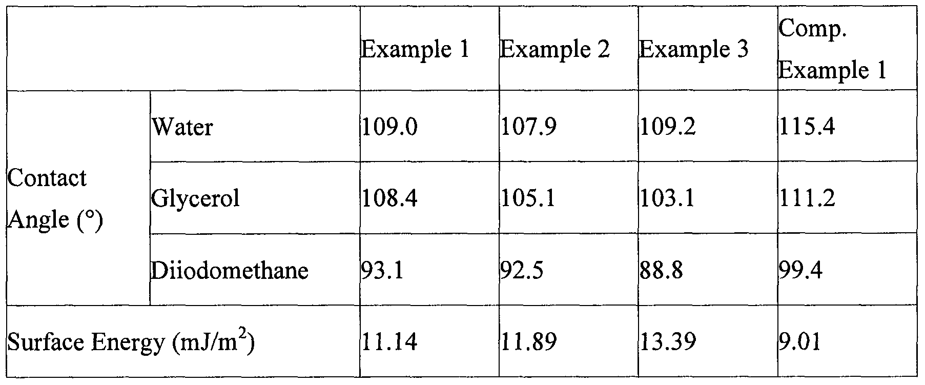
- the surface energy of the transparent coating layer ranges from 11 to 14 mJ/m 2 .
- the fluorine-containing elastomer used in the present invention has a high stickiness and simultaneously a high elasticity, and thus, when it is coated on the surface of a lens, it imparts to the lens a good resistance against rotational torque and a good adhesion to the lens, facilitating the lens edging process without using an adhesive tape, and at the same time preventing the contamination of the lens caused by contaminants or chemicals during handling while protecting the lens from damage caused by lens flakes generated during the edging procedure.
- the transparent coating layer comprising the fluorine-containing elastomer provides the advantages that it can be easily removed simply by hands, without using a chemical, after the completion of the edging process, and it makes possible to determine the exact diopter of lens owing to its high transparency.
- the fluorine-containing elastomer may be prepared by homopolymerizing or copolymerizing at least one monomer selected from the group consisting of chlorotrifluoroethylene, hexafluoropropylene, hexafluoroacetone, 1-hydropentafluoropropylene, perfluorovinyl ether, perf ⁇ uoromethylvinyl ether, trifluoroethylene, tetrafluoroethylene, and vinylidene fluoride.
- at least one comonomer selected from ethylene and propylene may be used.
- the fluorine-containing elastomer may be prepared by the methods disclosed in U.S. Patent Nos. 4,758,618; 4,591,616; 3,136,745; 6,294,627; and 4,418,186, and representative examples of commercially available fluorine- containing elastomer include DAIELTM(Daikin), DYNEONTM (3M), TECNOFLONTM (Solvay Solexis), VITONTM (DuPont) and AFLASTM (Asahi Glass).
- the transparent coating layer according to the present invention may further comprise a fluorine-containing organosilane compound in order to enhance the strength of the coating layer.
- the fluorine-containing organosilane compound used with the fluorine-containing elastomer functions to impart a low surface energy to the transparent coating layer, thus preventing the attachment of contaminants, and it provides good chemical and scratch resistances.
- fluorine-containing organosilane compound examples include an organosilane compound having fluorine-substituted alkyl groups represented by any one of formulas (1) to (4), and an organosilane compound having a perfluoropolyether group represented by formula (5), not limited thereto.
- R 1 is a hydrolyzable group
- R 2 is hydrogen or C 1-4 alkyl
- R 2 ' is C 1-4 alkyl
- R f 1 is a monovalent or divalent polyfluoropolyether group
- Q is an organic divalent bridging group; i, j, k, m and n are each independently an integer in the range of 0 to 13; m' is an integer in the range of 1 to 13; n' is an integer in the range of 0 to 3; p is an integer in the range of 0 to 3;
- I is 1 or 2; and x is O or l.
- the hydrolyzable group R 1 may be halogen, C 1-4 alkoxy, acyloxy, acyl and polyoxyalkylene such as polyoxyethylene (see U.S. Patent No. 5,274,159). Specific examples of the hydrolyzable group R 1 are methoxy, ethoxy, propoxy, chlorine and acetoxy.
- R f 1 is stable and inert, preferably saturated nonpolar fluoroaliphatic group.
- the fluoroaliphatic group may be a straight, branched or cyclic group, or a combination thereof, and it may contain at least one heterogeneous atom such as oxygen, 2- or 6- valent sulfur, or nitrogen.
- the fluoroaliphatic group may be completely fluorinated, although it may contain at most one hydrogen or chlorine substituent in every two carbon atoms.
- Suitable fluoroaliphatic group may contain 3 to 18 carbon atoms, preferably 3 to 14 carbon atoms, and more preferably 4 to 10 carbon atoms, and preferably about 40 to about 80 % by weight, and more preferably about 50 to about 79 % by weight of fluorine atoms.
- the end part of the fluoroaliphatic group may be a perfluorinated group having at least 7 fluorine atoms, e.g., CF 3 CF 2 CF 2 -, (CF 3 ) 2 CF-, and F 5 SCF 2 -.
- the preferred fluoroaliphatic group is completely or substantially fluorinated, and may include a perfluorinated aliphatic radical represented by C q F 2q+1 - where q is in the range of 3 to 18, preferably 4 to 10.
- R f 1 is a divalent polyfluoropoly ether group.
- the poly fluoropoly ether group may be a straight, branched or cyclic group, or a combination thereof, and it may be saturated or unsaturated, and preferably perfluorinated wherein all of C-H bonds are substituted with C-F bonds.
- the polyfluoropoly ether group may include a perfluorinated repeating unit selected from the group consisting of -(C q F 2q >, -(C q F 2q O)-, -(CF(Z))-, -(CF(Z)O)-, -(CF(Z)C q F 2q O)-, - (C q F 2q CF(Z)O)- and -(CF 2 CF(Z)O)- (where q is in the range of 3 to 18, preferably 4 to 10, and Z is a straight, branched or cyclic group, preferably an optionally oxygen-substituted perfluoroalkyl or perfluoroalkoxy group having about 1 to about 9 carbon atoms and 0 to about 4 oxygen atoms), and a combination thereof.
- Representative examples of the polyfluoropolyether group having the polymeric moiety of the perfluorinated repeating unit are disclosed in U.S. Patent No. 5,306,
- the divalent polyfluoropolyether group has preferably an average structure of -CF 2 O(CF 2 O) 1 -(C 2 F 4 O) 5 CF 2 - (wherein r and s are in the range of 0 to 50 in average, provided that both r and s are not 0), - CF(CF 3 )O(CF(CF 3 )CF 2 O) 1 CF(CF 3 )-, -CF 2 O(C 2 F 4 O) 1 CF 2 - and (CF 2 ) 3 O(C 4 F 8 O) t (CF 2 ) 3 - (wherein t is in the range of 3 to 50 in average).
- -CF 2 O(CF 2 O) 8 C 2 F 4 O) 1 CF 2 -
- CF(CF 3 )O(CF(CF 3 )CF 2 OXCF(CF 3 )- and -CF 2 O(C 2 F 4 O) 1 CF 2 - are more preferred.
- the divalent bridging group Q may be saturated or unsaturated straight, branched or cyclic group.
- Q may comprise a heterogeneous atom such as oxygen, nitrogen or sulphur, or a functional group such as carbonyl, amido, urethanylene or sulfonamindo.
- the divalent bridging group Q may be a non-fluorinated organic group, e.g., hydrocarbon, preferably a straight chain hydrocarbon, optionally comprising a heterogeneous atom or functional group, preferably at least one functional group.
- Q include -C(O)NH(CH 2 ) 3 -, -CH 2 O(CH 2 ) 3 -, - CH 2 OC(O)N(R)(CH 2 )S- (wherein, R is H or a lower alkyl) and -(C 8 H 211 )- (wherein, a is in the range of about 2 to about 6), preferably -C(O)NH(CH 2 ) 3 -.
- the fluorine-containing organosilane compound suitable for the present invention typically has a number average molecular weight of greater than about 200, preferably from about 1,000 to 10,000.
- fluorinated polyethersilane compounds represented by XCF 2 O(CF 2 O) f (C 2 F 4 O) 8 CF 2 X, XCF(CF 3 )O(CF(CF 3 )CF 2 O) g CF(CF 3 )X, XCF 2 O(C 2 F 4 O) 6 CF 2 X and X(CF 2 ) 3 O(C 4 F 8 O) g (CF 2 ) 3 X, wherein -X is -Q-SiY 3 .
- X K ⁇ , Q is an organic divalent bridging group, Y is a hydrolyzable group, R 1 is a Ci -4 alkyl group, and x is 0 or 1.
- Q comprises nitrogen atom. More preferably, in the compound, at least one X per molecule is C(O)NH(CH 2 ) 3 Si(OR) 3 wherein R is methyl, ethyl, polyethyleneoxy or a combination thereof.
- f and g may have various values, preferably f is between about 1 and about 50 and g is between about 4 and about 40.
- the lens-protective transparent coating layer according to the present invention may be formed by applying a composition for forming the transparent coating layer to the surface of the lens and drying the applied composition.
- the composition for forming the transparent coating layer may be obtained by dissolving a fluorine-containing elastomer in a solvent to a concentration of 1 to 70 % by weight, preferably 10 to 40 % by weight of a solid content.
- concentration of the elastomer is less than 1 % by weight, the transparent coating layer obtained has insufficient stickiness and elasticity, and when the concentration of the elastomer exceeds 70% by weight, the composition is unevenly coated.
- the transparent coating layer forming composition may comprise the above-mentioned fluorine-containing organosilane compound in an amount of 0.001 to 70 % by weight, preferably 0.001 to 30 % by weight based on the elastomer.
- the solvent used in the composition may be preferably at least one selected from the group consisting of water, perfluorohexane, perfluoroheptane, perfluorononane, perfluoromethylpentane, perfluorocyclohexane, perfluorodimethylcyclohexane, perfluorotoluene, hexafluoropropene oxide, trifluoroacetic anhydride, ethyl trifluoroacetate, octafluoropentanol, 2,2-bistrifluoromethylpropanol, pentafluoropropanol, hexadecafluorononanol, perfluoro-2-butanol, isopropyl alcohol, butanol, ethylene glycol, diacetone alcohol, 2-ethoxyethanol, 2-methoxyethanol, 2- butoxyethanol, hexane, heptane, cyclohexane, acetylacetone,
- the transparent coating layer forming composition may comprise a conventional additive well known in the art, such as surfactants and dyes, in amount not affecting the effect of the invention.
- the present invention comprises the lens coated with the transparent coating layer forming composition as a temporary protective layer within the scope thereof.
- the lens to which the transparent coating layer applied may be any one which can be processed by an edging process, and its representative examples may include glasses or camera lenses.
- the transparent coating layer-forming composition according to the present invention may be coated on the most outer layer of at least one functional layers formed on a lens, e.g., an inorganic oxide layer (anti- reflective layer), water-repellant layer and/or oil-repellant layer, preferably on water-repellant and/or oil-repellant layer.
- a lens e.g., an inorganic oxide layer (anti- reflective layer), water-repellant layer and/or oil-repellant layer, preferably on water-repellant and/or oil-repellant layer.
- the inorganic oxide layer as the anti-reflective layer may be at least one vacuum-deposited ceramic layer known in the art, and its representative examples may include SiO 2 , ZrO 2 , Al 2 O 3 , and TiO 2 .
- the water-repellant layer or oil-repellant layer to be formed on the surface of the inorganic oxide layer may comprise a fluorine- or perfluoropolyether-containing organosilane compound, and it has hydrophobic or oleophobic characteristics, respectively, which can reduce the surface energy of the glass.
- the fluorine- or perfluoropolyether-containing organosilane compound is well known in the art, e.g., Japanese Patent Application Publication Nos. 1986-130902, 1983-172246, 1983-122979,
- the transparent coating layer-forming composition may be applied in a suitable known method selected from a dip- coating, spray-coating, spin-coating, flow-coating, and roll-coating method, preferably a dip coating method.
- the transparent coating layer-forming composition may be dried at a temperature of 30-70 ° C , preferably 50-60 "C . If the temperature is lower than 30 ° C , the curing time is too long, and if the temperature exceeds 70 ° C, cracks generates on the anti-reflective layer.
- the curing time is preferably in the range of 1-15 minutes. If the curing time is shorter than 1 minute, the curing is incomplete, and if the curing time exceeds 15 minutes, the quality of lens deteriorates.
- the transparent coating layer may have a thickness of 0.1-100 ⁇ m, preferably 0.1 ⁇ 1 O ⁇ m. When the thickness is less than 0.1 ⁇ m, the coating layer is incompletely formed, and when the thickness exceeds lOO ⁇ m, the curing time is too long, thus lowering the productivity.
- the lens having the inventive transparent coating layer as a temporary protective layer may be edged using a conventional edging apparatus. In the edging process, the inventive transparent coating layer can prevent lens off- centring phenomena due to its inherent elasticity and appropriate affinity to the surface of the lens. Further, the inventive transparent coating layer makes it possible to measure the diopter of lens exactly owing to its transparency; and it is manually removable without any etching or chemical treatment.
- Plastic lens having anti-reflective layer, water-repellant layer, and oil-repellant layer coated on the surface thereof
- a hard coating layer was formed using a silicon-based hard coating agent (MEXMER TE0801, a product of Gaematech).
- MEXMER TE0801 a silicon-based hard coating agent
- the hard coating layer was formed using a dipping method at a withdrawing speed of 15 cm/min, drying the resulting coating layer at room temperature for 1 minute, and curing at 80 °C for 2 minutes and then at 120 ° C in a curing oven for 1.5 hours.
- anti-reflective layers comprised of silicone dioxide, zirconia and indium tin oxide (ITO) were formed by an e- beam evaporation method.
- the hard coating layer/anti-reflective layer-coated lens thus obtained and a stainless steel filter (a mesh size of 80-100 microns, 18 ⁇ ⁇ 3mm) impregnated with 2 ml of OPTOOL DSX (a product of Daikin) were placed in a vacuum deposition apparatus where a water-repellant layer and oil-repellant layer were deposited on the anti-reflective layer by a thermal evaporation method.
- Example 1 Formation of Transparent Coating layer 1
- a 10 wt% solution of DyneonTM THV220A (as a fluorine group-containing elastomer; a copolymer of vinylidene fluoride, tetrafluoroethylene and hexafluoropropene, 3M) dissolved in methyl ethyl ketone was coated as a protective layer for the lens using a dipping method at a withdrawing speed of 15 cm/min, and the coated lens was dried at 50 ° C for 5 minutes to form a lens-protective transparent coating layer having a thickness of 1.3 ⁇ m on the lens.
- DyneonTM THV220A as a fluorine group-containing elastomer; a copolymer of vinylidene fluoride, tetrafluoroethylene and hexafluoropropene, 3M
- Example 2 Formation of Transparent Coating layer 2
- the procedure of Example 1 was repeated except for using 50 wt% aqueous dispersion of DyneonTM THV340C (a copolymer of vinylidene fluoride, tetrafluoroethylene and hexafluoropropene, 3M) instead of the DyneonTM THV220A solution to form a lens-protective transparent coating layer having a thickness of 50 ⁇ m on the lens.
- DyneonTM THV340C a copolymer of vinylidene fluoride, tetrafluoroethylene and hexafluoropropene, 3M
- Example 3 Formation of Transparent Coating layer 3
- the procedure of Example 1 was repeated except for using a 20 wt% solution of VitonTM A (a copolymer of vinylidene fluoride and hexafluoropropene, DuPont) dissolved in methyl ethyl ketone instead of the D DyynneeoonnTM TTHHVV222200AA ssoolluuttiioonn ttoo ffoorrmm aa lleemns-protective transparent coating layer having a thickness of 18 ⁇ m on the lens.
- VitonTM A a copolymer of vinylidene fluoride and hexafluoropropene, DuPont
- reaction solution was cooled to room temperature, and distilled at 50 ° C under a pressure of 10 "1 mmHg to remove the residual solvent and water completely, to obtain 9g of the desired product, which was added to 500 g of methyl ethyl ketone, and thereto was added 50 g of DyneonTM THV220A (a copolymer of vinylidene fluoride, tetrafluoroethylene and hexafluoropropene, 3M) as a fluorine group-containing elastomer.
- DyneonTM THV220A a copolymer of vinylidene fluoride, tetrafluoroethylene and hexafluoropropene, 3M
- the resulting mixture was stirred for 1 hour to dissolve the components in the solvent completely, and then coated on the surface of the plastic lens obtained in Preparation, and thereafter, a 10 wt% solution of dissolved in methyl ethyl ketone was coated thereon as a protective layer for the lens using a dipping method at a withdrawing speed of 15 cm/min.
- the coated lens was dried at 50 ° C for 10 minutes to form a lens-protective transparent coating layer having a thickness of 1.5 ⁇ m on the lens.
- Example 5 Formation of Transparent Coating layer 5 The procedure of Example 4 was repeated except for using SIT8175
- Example 6 Formation of Transparent Coating layer 6 10 g of SIT8175 (tridecafluoro- 1 , 1 ,2,2-tetrahydrooctyl triethoxysilane,
- the resulting coating solution was coated on the surface of the plastic lens obtained in Preparation using a dipping method at a withdrawing speed of 15 cm/min, and the coated lens was dried at 50 0 C for 10 minutes to form a lens-protective transparent coating layer having a thickness of 2.0 ⁇ m on the lens.
- the lenses having the transparent coating layer for the protection thereof according to the present invention (Examples 1 to 6), the plastic lens before the formation of the transparent coating layer according to Preparation (Comparative Example 1), and the plastic lens to which a silicon-based adhesive film is attached (Comparative Example 2) were evaluated for various properties as described below, and the evaluation results are represented in Table 1.
- the light transmittances of the lens before and after coating with the transparent coating layer-forming composition according to the present invention at the visible light wavelength were determined using an apparatus for measuring the light transmittance (Haze Guide Plus, BYK Guidener).
- the diopters of the lens before and after coating with the transparent coating layer-forming composition according to the present invention were measured with a dioptometer (CLM3100P, Huvitz), to observe the change of lens diopter values depending on the formation of the transparent coating layer.
- the axis of the lens was defined as astigmatism-correction axis, and for a lens for non-astigmatism, the lens axis was defined as the optical central line, and a frame having a high aspect ratio was used as a base frame.
- ALE5000 they were mounted on the base frame to observe the off-centring degree of the astigmatism-correction axis or the angle of the optical central line to the horizontal line passing through the optical axis of the base frame, with a lensmeter.
- the lens after peeled the transparent coating layer therefrom by hands was tested with a contact angle tester (KSV Instrument CAM 100) to measure the change of the contact angle of the lens to water.
- the contact angles of the lenses to water, glycerol or diiodomethane were measured with a contact angle tester (DSAlOO, Kruss).
- the surface energy of the lens was determined by Owens-Wendt method using a drop shape analysis program (see “Estimation of the surface force energy of polymers” Owens D. K., et al., J. Appl. Polym. ScL 13, 1741-1747 (1969)).
Abstract
Description

Claims
Priority Applications (5)
| Application Number | Priority Date | Filing Date | Title |
|---|---|---|---|
| US12/092,697 US9134461B2 (en) | 2006-03-27 | 2007-03-27 | Edging process of lens using transparent coating layer for protecting lens |
| EP07745664.8A EP1999220B1 (en) | 2006-03-27 | 2007-03-27 | Edging process of lens using transparent coating layer for protecting lens |
| CA2647510A CA2647510C (en) | 2006-03-27 | 2007-03-27 | Edging process of lens using transparent coating layer for protecting lens |
| AU2007230045A AU2007230045B8 (en) | 2006-03-27 | 2007-03-27 | Edging process of lens using transparent coating layer for protecting lens |
| CN2007800193854A CN101454411B (en) | 2006-03-27 | 2007-03-27 | Edging process of lens using transparent coating layer for protecting lens |
Applications Claiming Priority (4)
| Application Number | Priority Date | Filing Date | Title |
|---|---|---|---|
| KR1020060027609A KR100687574B1 (en) | 2006-03-27 | 2006-03-27 | A transparent coating agent for blocking of lens and a edging process of lens using the same |
| KR10-2006-0027609 | 2006-03-27 | ||
| KR1020060065727A KR100689110B1 (en) | 2006-07-13 | 2006-07-13 | A composition for lens coating having a low surface energy and a coating process and a edging process of lens using the same |
| KR10-2006-0065727 | 2006-07-13 |
Publications (1)
| Publication Number | Publication Date |
|---|---|
| WO2007111465A1 true WO2007111465A1 (en) | 2007-10-04 |
Family
ID=38541351
Family Applications (1)
| Application Number | Title | Priority Date | Filing Date |
|---|---|---|---|
| PCT/KR2007/001491 WO2007111465A1 (en) | 2006-03-27 | 2007-03-27 | Edging process of lens using transparent coating layer for protecting lens |
Country Status (5)
| Country | Link |
|---|---|
| US (1) | US9134461B2 (en) |
| EP (1) | EP1999220B1 (en) |
| AU (1) | AU2007230045B8 (en) |
| CA (1) | CA2647510C (en) |
| WO (1) | WO2007111465A1 (en) |
Cited By (4)
| Publication number | Priority date | Publication date | Assignee | Title |
|---|---|---|---|---|
| WO2009156054A1 (en) * | 2008-06-26 | 2009-12-30 | Satisloh Ag | Method for manufacturing spectacle lenses according to a prescription |
| US8013064B2 (en) * | 2007-04-16 | 2011-09-06 | 3M Innovative Properties Company | Perfluoroelastomer composition and sealing material |
| RU2570884C1 (en) * | 2014-07-02 | 2015-12-10 | Федеральное государственное бюджетное учреждение науки Институт металлоорганической химии им. Г.А. Разуваева Российской академии наук | Composition for obtaining protective coatings with low refraction indexes |
| WO2023204026A1 (en) * | 2022-04-19 | 2023-10-26 | 信越化学工業株式会社 | Method for producing water- and oil-repellent article, and method for improving water and oil removability in water- and oil-repellent article |
Families Citing this family (5)
| Publication number | Priority date | Publication date | Assignee | Title |
|---|---|---|---|---|
| JP2013509610A (en) * | 2009-10-29 | 2013-03-14 | エルジー・ケム・リミテッド | Substrate having low reflection and high contact angle and method of manufacturing the same |
| US20130109795A1 (en) * | 2011-10-28 | 2013-05-02 | E. I. Du Pont De Nemours And Company | Fluoroelastomer composites having modified melt rheology |
| JP6286644B2 (en) * | 2014-05-30 | 2018-03-07 | 東海光学株式会社 | Coating agent for slippage prevention |
| EP3542956A1 (en) * | 2018-03-23 | 2019-09-25 | Carl Zeiss Vision International GmbH | Method for manufacturing spectacle lenses according to a prescription |
| WO2022071446A1 (en) * | 2020-09-30 | 2022-04-07 | 日油株式会社 | Resin composition for water-repellent lens protective films, and method for protecting water-repellent lens |
Citations (5)
| Publication number | Priority date | Publication date | Assignee | Title |
|---|---|---|---|---|
| JP2001122238A (en) * | 1999-10-28 | 2001-05-08 | Goyo Paper Working Co Ltd | Paper container and paper container manufacturing method |
| JP2004061866A (en) * | 2002-07-29 | 2004-02-26 | Seiko Epson Corp | Method for manufacturing stainproof spectacle lens |
| JP2004157147A (en) * | 2002-09-13 | 2004-06-03 | Seiko Epson Corp | Manufacture method for stainproof spectacle lens |
| WO2004111705A1 (en) * | 2003-06-10 | 2004-12-23 | Seiko Epson Corporation | Stainproof eyeglass lens and method for production thereof |
| KR20050017748A (en) * | 2003-08-08 | 2005-02-23 | 남상욱 | Lens having protection film that prevents moving of axis and damage of surface from the lens cutting, and method and coating solution thereof |
Family Cites Families (17)
| Publication number | Priority date | Publication date | Assignee | Title |
|---|---|---|---|---|
| US3136745A (en) | 1961-06-23 | 1964-06-09 | Du Pont | Elastomeric copolymers of vinylidene fluoride and perfluoroalkyl perfluorovinyl ethers |
| JPS57109810A (en) | 1980-12-26 | 1982-07-08 | Asahi Glass Co Ltd | Copolymer giving fluorine-containing elastomer with cold and alcohol resistance |
| JPS6157908A (en) | 1984-08-30 | 1986-03-25 | Seizo Miyata | Optical resin composition |
| JPS6286044A (en) | 1985-10-11 | 1987-04-20 | Asahi Glass Co Ltd | Vulcanizable composition |
| FR2751641B1 (en) * | 1996-07-26 | 1998-09-11 | Inst Francais Du Petrole | ISOALKANE/N-ALKANE SEPARATION PROCESS BY GAS PHASE ADSORPTION USING PRESSURE MODULATION AND FOUR ADSORBERS |
| JP4733798B2 (en) | 1998-01-31 | 2011-07-27 | 凸版印刷株式会社 | Antifouling agent, method for forming antifouling layer, optical member, antireflection optical member, optical functional member, and display device |
| US6294627B1 (en) | 1998-08-31 | 2001-09-25 | Dyneon Llc | Low temperature fluorocarbon elastomers |
| FR2824821B1 (en) | 2001-05-17 | 2003-08-29 | Essilor Int | PROCESS FOR THE PREPARATION OF A GLASS SUITABLE FOR OVERFLOWING, GLASS THUS OBTAINED AND METHOD FOR OVERFLOWING SUCH A GLASS |
| FR2834712B1 (en) | 2002-01-14 | 2004-12-17 | Essilor Int | PROCESS FOR TREATING OPHTHALMIC GLASS |
| JP2004226942A (en) | 2002-03-18 | 2004-08-12 | Hoya Corp | Optical member, method of manufacturing optical member, and method of manufacturing thin film |
| JP3750632B2 (en) | 2002-06-11 | 2006-03-01 | ダイキン工業株式会社 | A remote management system for equipment with a test run tool |
| JP3715601B2 (en) | 2002-08-05 | 2005-11-09 | ソーラオプティカルジャパン株式会社 | Axis misalignment prevention kit for use in eyeglass lens processing and eyeglass lens processing method using the same |
| FR2856056B1 (en) | 2003-06-13 | 2009-07-03 | Essilor Int | PROCESS FOR TREATING A GLASS FOR DEPTH. |
| DE102004044441B3 (en) * | 2004-09-14 | 2006-06-01 | Rodenstock Gmbh | Improvement of the grinding and stamping behavior of spectacle lenses with hydrophobic coating |
| US20070141358A1 (en) * | 2005-12-19 | 2007-06-21 | Essilor International Compagnie Generale D'optique | Method for improving the edging of an optical article by providing a temporary layer of an organic material |
| EP2057008B1 (en) | 2006-08-09 | 2016-03-02 | Innovation Chemical Technologies, Ltd. | Nano structured phased hydrophobic layers on substrates |
| FR2907915B1 (en) | 2006-10-31 | 2009-01-23 | Essilor Int | OPTICAL ARTICLE COMPRISING ANTI-SOIL COATING |
-
2007
- 2007-03-27 CA CA2647510A patent/CA2647510C/en not_active Expired - Fee Related
- 2007-03-27 WO PCT/KR2007/001491 patent/WO2007111465A1/en active Application Filing
- 2007-03-27 AU AU2007230045A patent/AU2007230045B8/en not_active Ceased
- 2007-03-27 EP EP07745664.8A patent/EP1999220B1/en active Active
- 2007-03-27 US US12/092,697 patent/US9134461B2/en active Active
Patent Citations (5)
| Publication number | Priority date | Publication date | Assignee | Title |
|---|---|---|---|---|
| JP2001122238A (en) * | 1999-10-28 | 2001-05-08 | Goyo Paper Working Co Ltd | Paper container and paper container manufacturing method |
| JP2004061866A (en) * | 2002-07-29 | 2004-02-26 | Seiko Epson Corp | Method for manufacturing stainproof spectacle lens |
| JP2004157147A (en) * | 2002-09-13 | 2004-06-03 | Seiko Epson Corp | Manufacture method for stainproof spectacle lens |
| WO2004111705A1 (en) * | 2003-06-10 | 2004-12-23 | Seiko Epson Corporation | Stainproof eyeglass lens and method for production thereof |
| KR20050017748A (en) * | 2003-08-08 | 2005-02-23 | 남상욱 | Lens having protection film that prevents moving of axis and damage of surface from the lens cutting, and method and coating solution thereof |
Cited By (5)
| Publication number | Priority date | Publication date | Assignee | Title |
|---|---|---|---|---|
| US8013064B2 (en) * | 2007-04-16 | 2011-09-06 | 3M Innovative Properties Company | Perfluoroelastomer composition and sealing material |
| WO2009156054A1 (en) * | 2008-06-26 | 2009-12-30 | Satisloh Ag | Method for manufacturing spectacle lenses according to a prescription |
| EP2138271A1 (en) * | 2008-06-26 | 2009-12-30 | Satisloh AG | Method for manufacturing spectacle lenses according to a prescription |
| RU2570884C1 (en) * | 2014-07-02 | 2015-12-10 | Федеральное государственное бюджетное учреждение науки Институт металлоорганической химии им. Г.А. Разуваева Российской академии наук | Composition for obtaining protective coatings with low refraction indexes |
| WO2023204026A1 (en) * | 2022-04-19 | 2023-10-26 | 信越化学工業株式会社 | Method for producing water- and oil-repellent article, and method for improving water and oil removability in water- and oil-repellent article |
Also Published As
| Publication number | Publication date |
|---|---|
| EP1999220A1 (en) | 2008-12-10 |
| AU2007230045B8 (en) | 2013-02-14 |
| CA2647510A1 (en) | 2007-10-04 |
| US9134461B2 (en) | 2015-09-15 |
| EP1999220B1 (en) | 2019-02-13 |
| AU2007230045A1 (en) | 2007-10-04 |
| CA2647510C (en) | 2015-05-12 |
| AU2007230045A8 (en) | 2013-02-21 |
| AU2007230045B2 (en) | 2013-01-10 |
| EP1999220A4 (en) | 2017-02-22 |
| US20080292787A1 (en) | 2008-11-27 |
Similar Documents
| Publication | Publication Date | Title |
|---|---|---|
| CA2647510C (en) | Edging process of lens using transparent coating layer for protecting lens | |
| KR100940086B1 (en) | Per-fluoro polyether compound, antifouling coating composition and film containing same | |
| EP1300433B1 (en) | Perfluoropolyether-modified silane, surface treating agent, and antireflection filter | |
| US11624858B2 (en) | Antireflective member and method of manufacture therefor | |
| US6958191B2 (en) | Lens with stain resistant surface layer | |
| EP2617775B1 (en) | Fluorinated hybrid compositions | |
| EP2617776B1 (en) | Articles containing fluorinated hybrid compositions | |
| JP2004145283A (en) | Lens with stainproof surface layer | |
| CN101454411B (en) | Edging process of lens using transparent coating layer for protecting lens | |
| US20220259454A1 (en) | Film and substrate having surface covered with same | |
| WO2011011653A2 (en) | Method of preparing fluorinated hybrid compositions | |
| EP1828324B1 (en) | Fluoropolymer coatings containing telomers | |
| JP4420476B2 (en) | Composition for surface modification film, surface modification film, filter for display device, display device and method for producing filter for display device | |
| KR100689110B1 (en) | A composition for lens coating having a low surface energy and a coating process and a edging process of lens using the same | |
| JPH11209685A (en) | Coating composition for optical article | |
| JP2009109611A (en) | Plastic spectacle lens with protective coat film | |
| JP2009109612A (en) | Method of forming protective coat film | |
| JP4396232B2 (en) | Method for producing antifouling optical article | |
| JP5624933B2 (en) | X-ray performance evaluation method and use thereof | |
| JP2004051849A (en) | Low-refractive-index coating agent and optical article |
Legal Events
| Date | Code | Title | Description |
|---|---|---|---|
| WWE | Wipo information: entry into national phase |
Ref document number: 200780019385.4 Country of ref document: CN |
|
| 121 | Ep: the epo has been informed by wipo that ep was designated in this application |
Ref document number: 07745664 Country of ref document: EP Kind code of ref document: A1 |
|
| WWE | Wipo information: entry into national phase |
Ref document number: 12092697 Country of ref document: US |
|
| WWE | Wipo information: entry into national phase |
Ref document number: 2647510 Country of ref document: CA Ref document number: 2007745664 Country of ref document: EP |
|
| WWE | Wipo information: entry into national phase |
Ref document number: 8127/DELNP/2008 Country of ref document: IN |
|
| WWE | Wipo information: entry into national phase |
Ref document number: 2007230045 Country of ref document: AU |
|
| NENP | Non-entry into the national phase |
Ref country code: DE |
|
| ENP | Entry into the national phase |
Ref document number: 2007230045 Country of ref document: AU Date of ref document: 20070327 Kind code of ref document: A |