WO2006088296A1 - Retardation film having a homeotropic alignment liquid crystal film and method for preparing the same - Google Patents
Retardation film having a homeotropic alignment liquid crystal film and method for preparing the same Download PDFInfo
- Publication number
- WO2006088296A1 WO2006088296A1 PCT/KR2006/000455 KR2006000455W WO2006088296A1 WO 2006088296 A1 WO2006088296 A1 WO 2006088296A1 KR 2006000455 W KR2006000455 W KR 2006000455W WO 2006088296 A1 WO2006088296 A1 WO 2006088296A1
- Authority
- WO
- WIPO (PCT)
- Prior art keywords
- liquid crystal
- film
- retardation film
- polarizing
- homeotropic alignment
- Prior art date
- Legal status (The legal status is an assumption and is not a legal conclusion. Google has not performed a legal analysis and makes no representation as to the accuracy of the status listed.)
- Ceased
Links
Classifications
-
- G—PHYSICS
- G02—OPTICS
- G02F—OPTICAL DEVICES OR ARRANGEMENTS FOR THE CONTROL OF LIGHT BY MODIFICATION OF THE OPTICAL PROPERTIES OF THE MEDIA OF THE ELEMENTS INVOLVED THEREIN; NON-LINEAR OPTICS; FREQUENCY-CHANGING OF LIGHT; OPTICAL LOGIC ELEMENTS; OPTICAL ANALOGUE/DIGITAL CONVERTERS
- G02F1/00—Devices or arrangements for the control of the intensity, colour, phase, polarisation or direction of light arriving from an independent light source, e.g. switching, gating or modulating; Non-linear optics
- G02F1/01—Devices or arrangements for the control of the intensity, colour, phase, polarisation or direction of light arriving from an independent light source, e.g. switching, gating or modulating; Non-linear optics for the control of the intensity, phase, polarisation or colour
- G02F1/13—Devices or arrangements for the control of the intensity, colour, phase, polarisation or direction of light arriving from an independent light source, e.g. switching, gating or modulating; Non-linear optics for the control of the intensity, phase, polarisation or colour based on liquid crystals, e.g. single liquid crystal display cells
- G02F1/133—Constructional arrangements; Operation of liquid crystal cells; Circuit arrangements
- G02F1/1333—Constructional arrangements; Manufacturing methods
- G02F1/1335—Structural association of cells with optical devices, e.g. polarisers or reflectors
-
- G—PHYSICS
- G02—OPTICS
- G02F—OPTICAL DEVICES OR ARRANGEMENTS FOR THE CONTROL OF LIGHT BY MODIFICATION OF THE OPTICAL PROPERTIES OF THE MEDIA OF THE ELEMENTS INVOLVED THEREIN; NON-LINEAR OPTICS; FREQUENCY-CHANGING OF LIGHT; OPTICAL LOGIC ELEMENTS; OPTICAL ANALOGUE/DIGITAL CONVERTERS
- G02F1/00—Devices or arrangements for the control of the intensity, colour, phase, polarisation or direction of light arriving from an independent light source, e.g. switching, gating or modulating; Non-linear optics
- G02F1/01—Devices or arrangements for the control of the intensity, colour, phase, polarisation or direction of light arriving from an independent light source, e.g. switching, gating or modulating; Non-linear optics for the control of the intensity, phase, polarisation or colour
- G02F1/13—Devices or arrangements for the control of the intensity, colour, phase, polarisation or direction of light arriving from an independent light source, e.g. switching, gating or modulating; Non-linear optics for the control of the intensity, phase, polarisation or colour based on liquid crystals, e.g. single liquid crystal display cells
- G02F1/133—Constructional arrangements; Operation of liquid crystal cells; Circuit arrangements
- G02F1/1333—Constructional arrangements; Manufacturing methods
- G02F1/1335—Structural association of cells with optical devices, e.g. polarisers or reflectors
- G02F1/13363—Birefringent elements, e.g. for optical compensation
-
- C—CHEMISTRY; METALLURGY
- C09—DYES; PAINTS; POLISHES; NATURAL RESINS; ADHESIVES; COMPOSITIONS NOT OTHERWISE PROVIDED FOR; APPLICATIONS OF MATERIALS NOT OTHERWISE PROVIDED FOR
- C09K—MATERIALS FOR MISCELLANEOUS APPLICATIONS, NOT PROVIDED FOR ELSEWHERE
- C09K19/00—Liquid crystal materials
- C09K19/04—Liquid crystal materials characterised by the chemical structure of the liquid crystal components, e.g. by a specific unit
- C09K19/06—Non-steroidal liquid crystal compounds
- C09K19/08—Non-steroidal liquid crystal compounds containing at least two non-condensed rings
- C09K19/30—Non-steroidal liquid crystal compounds containing at least two non-condensed rings containing saturated or unsaturated non-aromatic rings, e.g. cyclohexane rings
- C09K19/3098—Unsaturated non-aromatic rings, e.g. cyclohexene rings
-
- G—PHYSICS
- G02—OPTICS
- G02B—OPTICAL ELEMENTS, SYSTEMS OR APPARATUS
- G02B5/00—Optical elements other than lenses
- G02B5/30—Polarising elements
- G02B5/3016—Polarising elements involving passive liquid crystal elements
-
- C—CHEMISTRY; METALLURGY
- C09—DYES; PAINTS; POLISHES; NATURAL RESINS; ADHESIVES; COMPOSITIONS NOT OTHERWISE PROVIDED FOR; APPLICATIONS OF MATERIALS NOT OTHERWISE PROVIDED FOR
- C09K—MATERIALS FOR MISCELLANEOUS APPLICATIONS, NOT PROVIDED FOR ELSEWHERE
- C09K19/00—Liquid crystal materials
- C09K19/04—Liquid crystal materials characterised by the chemical structure of the liquid crystal components, e.g. by a specific unit
- C09K2019/0444—Liquid crystal materials characterised by the chemical structure of the liquid crystal components, e.g. by a specific unit characterized by a linking chain between rings or ring systems, a bridging chain between extensive mesogenic moieties or an end chain group
- C09K2019/0448—Liquid crystal materials characterised by the chemical structure of the liquid crystal components, e.g. by a specific unit characterized by a linking chain between rings or ring systems, a bridging chain between extensive mesogenic moieties or an end chain group the end chain group being a polymerizable end group, e.g. -Sp-P or acrylate
-
- C—CHEMISTRY; METALLURGY
- C09—DYES; PAINTS; POLISHES; NATURAL RESINS; ADHESIVES; COMPOSITIONS NOT OTHERWISE PROVIDED FOR; APPLICATIONS OF MATERIALS NOT OTHERWISE PROVIDED FOR
- C09K—MATERIALS FOR MISCELLANEOUS APPLICATIONS, NOT PROVIDED FOR ELSEWHERE
- C09K2323/00—Functional layers of liquid crystal optical display excluding electroactive liquid crystal layer characterised by chemical composition
-
- C—CHEMISTRY; METALLURGY
- C09—DYES; PAINTS; POLISHES; NATURAL RESINS; ADHESIVES; COMPOSITIONS NOT OTHERWISE PROVIDED FOR; APPLICATIONS OF MATERIALS NOT OTHERWISE PROVIDED FOR
- C09K—MATERIALS FOR MISCELLANEOUS APPLICATIONS, NOT PROVIDED FOR ELSEWHERE
- C09K2323/00—Functional layers of liquid crystal optical display excluding electroactive liquid crystal layer characterised by chemical composition
- C09K2323/02—Alignment layer characterised by chemical composition
-
- C—CHEMISTRY; METALLURGY
- C09—DYES; PAINTS; POLISHES; NATURAL RESINS; ADHESIVES; COMPOSITIONS NOT OTHERWISE PROVIDED FOR; APPLICATIONS OF MATERIALS NOT OTHERWISE PROVIDED FOR
- C09K—MATERIALS FOR MISCELLANEOUS APPLICATIONS, NOT PROVIDED FOR ELSEWHERE
- C09K2323/00—Functional layers of liquid crystal optical display excluding electroactive liquid crystal layer characterised by chemical composition
- C09K2323/03—Viewing layer characterised by chemical composition
- C09K2323/031—Polarizer or dye
-
- G—PHYSICS
- G02—OPTICS
- G02F—OPTICAL DEVICES OR ARRANGEMENTS FOR THE CONTROL OF LIGHT BY MODIFICATION OF THE OPTICAL PROPERTIES OF THE MEDIA OF THE ELEMENTS INVOLVED THEREIN; NON-LINEAR OPTICS; FREQUENCY-CHANGING OF LIGHT; OPTICAL LOGIC ELEMENTS; OPTICAL ANALOGUE/DIGITAL CONVERTERS
- G02F1/00—Devices or arrangements for the control of the intensity, colour, phase, polarisation or direction of light arriving from an independent light source, e.g. switching, gating or modulating; Non-linear optics
- G02F1/01—Devices or arrangements for the control of the intensity, colour, phase, polarisation or direction of light arriving from an independent light source, e.g. switching, gating or modulating; Non-linear optics for the control of the intensity, phase, polarisation or colour
- G02F1/13—Devices or arrangements for the control of the intensity, colour, phase, polarisation or direction of light arriving from an independent light source, e.g. switching, gating or modulating; Non-linear optics for the control of the intensity, phase, polarisation or colour based on liquid crystals, e.g. single liquid crystal display cells
- G02F1/133—Constructional arrangements; Operation of liquid crystal cells; Circuit arrangements
- G02F1/1333—Constructional arrangements; Manufacturing methods
- G02F1/1335—Structural association of cells with optical devices, e.g. polarisers or reflectors
- G02F1/13363—Birefringent elements, e.g. for optical compensation
- G02F1/133633—Birefringent elements, e.g. for optical compensation using mesogenic materials
-
- G—PHYSICS
- G02—OPTICS
- G02F—OPTICAL DEVICES OR ARRANGEMENTS FOR THE CONTROL OF LIGHT BY MODIFICATION OF THE OPTICAL PROPERTIES OF THE MEDIA OF THE ELEMENTS INVOLVED THEREIN; NON-LINEAR OPTICS; FREQUENCY-CHANGING OF LIGHT; OPTICAL LOGIC ELEMENTS; OPTICAL ANALOGUE/DIGITAL CONVERTERS
- G02F1/00—Devices or arrangements for the control of the intensity, colour, phase, polarisation or direction of light arriving from an independent light source, e.g. switching, gating or modulating; Non-linear optics
- G02F1/01—Devices or arrangements for the control of the intensity, colour, phase, polarisation or direction of light arriving from an independent light source, e.g. switching, gating or modulating; Non-linear optics for the control of the intensity, phase, polarisation or colour
- G02F1/13—Devices or arrangements for the control of the intensity, colour, phase, polarisation or direction of light arriving from an independent light source, e.g. switching, gating or modulating; Non-linear optics for the control of the intensity, phase, polarisation or colour based on liquid crystals, e.g. single liquid crystal display cells
- G02F1/133—Constructional arrangements; Operation of liquid crystal cells; Circuit arrangements
- G02F1/1333—Constructional arrangements; Manufacturing methods
- G02F1/1335—Structural association of cells with optical devices, e.g. polarisers or reflectors
- G02F1/13363—Birefringent elements, e.g. for optical compensation
- G02F1/133634—Birefringent elements, e.g. for optical compensation the refractive index Nz perpendicular to the element surface being different from in-plane refractive indices Nx and Ny, e.g. biaxial or with normal optical axis
-
- G—PHYSICS
- G02—OPTICS
- G02F—OPTICAL DEVICES OR ARRANGEMENTS FOR THE CONTROL OF LIGHT BY MODIFICATION OF THE OPTICAL PROPERTIES OF THE MEDIA OF THE ELEMENTS INVOLVED THEREIN; NON-LINEAR OPTICS; FREQUENCY-CHANGING OF LIGHT; OPTICAL LOGIC ELEMENTS; OPTICAL ANALOGUE/DIGITAL CONVERTERS
- G02F1/00—Devices or arrangements for the control of the intensity, colour, phase, polarisation or direction of light arriving from an independent light source, e.g. switching, gating or modulating; Non-linear optics
- G02F1/01—Devices or arrangements for the control of the intensity, colour, phase, polarisation or direction of light arriving from an independent light source, e.g. switching, gating or modulating; Non-linear optics for the control of the intensity, phase, polarisation or colour
- G02F1/13—Devices or arrangements for the control of the intensity, colour, phase, polarisation or direction of light arriving from an independent light source, e.g. switching, gating or modulating; Non-linear optics for the control of the intensity, phase, polarisation or colour based on liquid crystals, e.g. single liquid crystal display cells
- G02F1/133—Constructional arrangements; Operation of liquid crystal cells; Circuit arrangements
- G02F1/1333—Constructional arrangements; Manufacturing methods
- G02F1/1343—Electrodes
- G02F1/134309—Electrodes characterised by their geometrical arrangement
- G02F1/134363—Electrodes characterised by their geometrical arrangement for applying an electric field parallel to the substrate, i.e. in-plane switching [IPS]
-
- G—PHYSICS
- G02—OPTICS
- G02F—OPTICAL DEVICES OR ARRANGEMENTS FOR THE CONTROL OF LIGHT BY MODIFICATION OF THE OPTICAL PROPERTIES OF THE MEDIA OF THE ELEMENTS INVOLVED THEREIN; NON-LINEAR OPTICS; FREQUENCY-CHANGING OF LIGHT; OPTICAL LOGIC ELEMENTS; OPTICAL ANALOGUE/DIGITAL CONVERTERS
- G02F2413/00—Indexing scheme related to G02F1/13363, i.e. to birefringent elements, e.g. for optical compensation, characterised by the number, position, orientation or value of the compensation plates
- G02F2413/02—Number of plates being 2
-
- G—PHYSICS
- G02—OPTICS
- G02F—OPTICAL DEVICES OR ARRANGEMENTS FOR THE CONTROL OF LIGHT BY MODIFICATION OF THE OPTICAL PROPERTIES OF THE MEDIA OF THE ELEMENTS INVOLVED THEREIN; NON-LINEAR OPTICS; FREQUENCY-CHANGING OF LIGHT; OPTICAL LOGIC ELEMENTS; OPTICAL ANALOGUE/DIGITAL CONVERTERS
- G02F2413/00—Indexing scheme related to G02F1/13363, i.e. to birefringent elements, e.g. for optical compensation, characterised by the number, position, orientation or value of the compensation plates
- G02F2413/07—All plates on one side of the LC cell
Definitions
- the present invention relates to a retardation film having a homeotropic alignment liquid crystal film, a polarizing film, an IPS (In-Plane Switching) mode liquid crystal display and a method for preparing the same. More particularly, the present invention relates to a homeotropic alignment liquid crystal film prepared from a liquid crystal mixed solution containing a polymerizable reactive liquid crystal monomer so as to improve a viewing angle characteristic of an ISP mode liquid crystal display and reduce a color shift; a retardation film prepared by integrating an oriented retardation film and a method for preparing the same; a polarizing film having the retardation film located between a polarizing element or plate and a liquid crystal cell and a method for preparing the same; and an IPS mode liquid crystal display having the polarizing film.
- a narrow viewing angle is one of the most vulnerable points of a liquid crystal display having good points in terms of lightweight, thin type, low power consumption and the like.
- the narrow viewing angle means that a completely different image is displayed on a display screen depending on a direction to which a person sees the display screen.
- the reason why an image is differently seen depending on a viewing angle in a liquid crystal display results from the anisotropy of liquid crystal and imperfection of a polarizing plate.
- the viewing angle refers to an angle at which a contrast ratio is usually 10:1 or more. To this end, a dark state being a completely dark state and uniform brightness are required. A variety of attempts for improving a viewing angle of a liquid crystal display have been made considering such requirements.
- Nematic mode is used a method such as a compensation film, DDTN (Dual-Domain TN), MDTN (Multi-Domain TN) or the like.
- VA Vertical Alignment
- a normally black mode in which an initial alignment direction is set to be a vertical direction is used contrary to a TN mode liquid crystal display frequently using a normally white mode so that a complete dark state is achieved due to a dark state by means of two sheets of front and rear polarizing plates, thereby increasing a contrast ratio.
- In IPS (In-Plane Switching) mode a method in that liquid crystal is rotated on a plane when the liquid crystal is horizontally aligned, and two electrodes are driven on one substrate so that light is transmitted or shielded, thereby improving an optical viewing angle.
- IPS In-Plane Switching
- the IPS mode since light quantity is controlled by means of horizontal movement of liquid crystal in the IPS mode so that a viewing angle characteristic becomes considerably better, the IPS mode is being used in a large number of products at present. Contrary to the VA mode, the IPS mode has superior characteristics of a viewing angle and a color shift even in a state where a retardation film is not basically applied.
- U.S. Patent No. 6,115,095 discloses that there are suggested structures where +C-PLATE, which is a positive uniaxial, optical anisotropic film and perpendicular to a plane with respect to an optical axis, is attached, and +A-PLATE, which is a positive uniaxial, optical anisotropic film and parallel to a plane with respect to an optical axis, is attached so that these retardation films are applied to the IPS mode, thereby obtaining more superior characteristics of a viewing angle and a color shift.
- +C-PLATE which is a positive uniaxial, optical anisotropic film and perpendicular to a plane with respect to an optical axis
- a retardation characteristic is controlled through an appropriate method in that a film is made of a polymer is processed to extend, or a refractive index of a thickness direction is controlled so that such a retardation film can be obtained.
- the retardation film may be obtained through a method in that a sheet or two sheets of heat- shrinkable films is adhered to a single surface or double surfaces of a film using an adhesive layer or the like, and a contractile force of the heat-shrinkable film is then added to film by means of heat so that the film is extended or contracted in a longitudinal or lateral direction, or both directions under the contractile force.
- alignment films which are made of various liquid crystal polymers such as a discotic or nematic system, of which alignment layer is supported by a film substrate, or the likes are used as the retardation film.
- Japanese Patent Laid-open Publication No. 2003-149441 discloses a retardation film wherein C-PLATE, which is a homeotropic alignment liquid crystal film formed from a homeotropic alignment liquid crystal composition containing a homeotropic alignment side-chain liquid crystal polymer or a correspondent side-chain liquid crystal polymer, and a photopolymerizable liquid crystal compound, and A- PLATE, which is an oriented film with a function of retardation, are laminated and integrated so that a retardation of a thickness direction can be widely controlled.
- C-PLATE which is a homeotropic alignment liquid crystal film formed from a homeotropic alignment liquid crystal composition containing a homeotropic alignment side-chain liquid crystal polymer or a correspondent side-chain liquid crystal polymer, and a photopolymerizable liquid crystal compound
- A- PLATE which is an oriented film with a function of retardation
- a side-chain liquid crystal polymer which is a liquid crystal polymer for forming a homeotropic alignment liquid crystal film and comprises a monomer unit (a) containing a liquid crystalline fragment side-chain with a positive refractive index anisotropy and a monomer unit (b) containing a non-liquid crystalline fragment side-chain, is used;
- the side-chain liquid crystal polymer has the monomer unit (b) containing a non-liquid crystalline fragment side-chain with a alkyl chain and the like except the monomer unit (a) containing a liquid crystalline fragment side-chain included in an ordinary side- chain liquid crystal polymer; and although a hometropic alignment film is not used, a nematic liquid crystal phase is revealed as a liquid crystal state through an operation of a monomer unit containing the non-liquid crystalline fragment side-chain, e.g., through a heat treatment so that a homeotropic alignment can be shown.
- Paten Laid-open Publication Nos. 2001-166133 and 2000-227520 has a limitation on its extension to a thickness direction, and there is a problem in that a retardation of the thickness direction cannot be widely controlled. Further, the method of contracting a retardation film by adding the contraction force of a heat-shrinkable film to a film has a problem in that the thickness of the retardation film becomes thick in the range of about 50 to IOOD so that requirement of reduction in thickness is not sufficiently met.
- the method of forming a homeotropic alignment liquid crystal film using a side-chain liquid crystal polymer as disclosed in the Japanese Patent Laid-open Publication No. 2003-149441 has problems in that since a glass transition temperature (Tg), which is a heat treatment temperature allowing the homeotropic alignment liquid crystal film to have a liquid crystal phase, is usually in the range of 60 to 300°C, more specifically in the range of 70 to 200°C, there is required a high temperature heat treatment process; that since time consumed in the heat treatment is also in the range of 20 seconds to 30 minutes, it is difficult to apply the method to a high-speed continuous process; that since there is required a cooling operation of air-cooling, water-cooling or the like to fix the alignment of the homeotropic alignment liquid crystal film after the heat treatment has been finished, it is difficult to apply the method to a continuous process; and that a liquid crystal polymer compound containing a liquid crystal polymer has a low solubility of a compatible solvent.
- Tg glass transition temperature
- an object of the present invention is to provide a new retardation film wherein a contrast ratio of an IPS mode liquid crystal display can be more increased, a color shift can be more reduced, and a retardation of a thickness direction can be widely controlled.
- Another object of the present invention is to provide a method for preparing a retardation film, wherein there are not required high temperature heat treatment and cooling processes for a long time so that the method can be applied to a high-speed continuous process.
- a further object of the present invention is to provide a polarizing film wherein the retardation film is attached on one surface of a polarizing element or polarizing plate adjacent to a liquid crystal cell so that the retardation film is located between the polarizing element or polarizing plate, and a method for preparing the same.
- a still further object of the present invention is to provide an IPS mode liquid crystal display including the polarizing film.
- a retardation film wherein an oriented film and a homeotropic alignment liquid crystal film formed from a solution containing a polymerizable reactive liquid crystal monomer are laminated such that they are integrated, and the contrast ratio and color shift characteristic of an IPS liquid crystal display are largely improved by a polarizing film in which the retardation film is laminated between a polarizing element or polarizing plate comprising the polarizing element and a transparent protection film, and a liquid crystal cell.
- the homeotropic alignment liquid crystal film is such a homeotropic alignment liquid crystal film wherein a liquid crystal layer with a homeotropic alignment property is prepared by coating, drying and UV light radiating a polymerizable liquid crystal mixed solution containing a surfactant and a reactive liquid crystal monomer on a surface of an oriented retardation film of which surface is treated to be hydrophilic, so that there is needed no additional alignment film.
- the reactive liquid crystal monomer is a reactor combined with neighboring liquid crystal monomers by means of light or heat and may use one or more of those selected from the group having an acrylate group attached thereto.
- a material of the oriented retardation film is one or more of those selected from the group consisting of triacetyl cellulose, polyethylene terephtalate, polymethyl methacrylate, polycarbonate, polyethylene and cycloolefin polymer such as norbornene derivatives, polyvinyl alcohol, diacetyl cellulose, polyether sulfone, it is not limited thereto.
- a method for preparing a retardation film comprising a step of preparing a retardation film in which a homeotropic alignment liquid crystal film is formed by coating, drying and UV light radiating a polymerizable liquid crystal mixed solution containing a surfactant and a reactive liquid crystal monomer on a surface of an oriented retardation film of which surface is treated to be hydrophilic, so that the oriented retardation film and the homeotropic alignment liquid crystal film are integrated.
- a method for preparing a retardation film comprising the steps of: preparing a homeotropic alignment liquid crystal film by coating, drying and UV light radiating a solution containing a surfactant and a polymerizable reactive liquid crystal monomer on a plastic substrate of which surface is treated to be hydrophilic; and attaching an oriented retardation film on the homeotropic alignment liquid crystal film using an adhesive such that they are integrated.
- FIG. 1 is a view showing a shift curve of a retardation value depending on a viewing angle of a homeotropic alignment liquid crystal film obtained through Embodiment 1.
- FIG. 2 is an exploded perspective view showing a sectional structure of a first preferred embodiment in which a retardation film according to the present invention is arranged between a polarizing plate and a liquid crystal cell.
- FIG. 3 is an exploded perspective view showing a structure in which a retardation film is not arranged between a polarizing plate and a liquid crystal cell.
- FIG. 4 is an exploded perspective view showing a structure in which only an oriented retardation film is arranged between a polarizing plate and a liquid crystal cell.
- FIG. 5 is a graph showing a contrast ratio when an incident angle is shifted to 80 degrees at an azimuth angle of 45 degrees with respect to each structure of FIGS. 2 to 4.
- FIG. 6 is a view showing an azimuth angle ( ⁇ ) and a polar angle ( ⁇ ) in a spherical coordination system.
- FIG. 7 is a graph shown a color shift characteristic of a preferred embodiment according to the present invention.
- FIG. 8 is a graph showing a color shift characteristic of a liquid crystal display with a structure of FIG. 3.
- FIG. 9 is a graph showing a color shift characteristic of a liquid crystal display with a structure of FIG. 4.
- FIG. 10 is a view showing a structure after polymerizing a reactive liquid crystal monomer of Chemical Formula 1 or Chemical Formula 2.
- FIG. 11 is a view showing a structure after polymerizing a reactive liquid crystal monomer of Chemical Formula 3.
- FIG. 12 is a view a shift curve of a retardation value depending on a viewing angle of a homeotropic alignment liquid crystal film obtained through Comparative Example. Best Mode for Carrying Out the Invention
- a retardation film provided by the present invention can be obtained by first fabricating a homeotropic alignment liquid crystal film from a liquid crystal mixed solution containing a polymerizable reactive liquid crystal monomer and then laminating an oriented retardation film on the homeotropic alignment liquid crystal film such that they are integrated.
- the content of a solid made of the liquid crystal contained in the liquid crystal mixed solution and a photoinitiator is different depending on a thickness of a liquid crystal layer and a coating method, it is not specifically limited thereto but is preferably composed of 10 to 50 wt% in the total liquid crystal mixed solution.
- the photoinitiator is preferably composed of 3 to 10 wt% of the total solid of 100 wt%.
- a liquid phase surfactant of 0.3 to 3 wt% is added with the total solid as reference, and a glass substrate being a typical hydrophilic substrate or a plastic substrate of which surface is treated to be hydrophilic is used as a substrate on which the liquid crystal mixed solution is coated.
- the surfactant is classified into a fluorocarbon-based surfactant and a silicon-based surfactant.
- Novec product name
- FC4430 and Novec FC4432 produced by 3M in U.S.A.
- Zonyl produced by Dupont in U.S.A., or the like is used as the fluorocarbon- based surfactant
- BYK product name produced by BYK-Chemie is used as the silicon-based surfactant.
- the content of the surfactant is preferably 0.3 to 3.0 wt% with the total mass of the solid contained in the total solution by reference. This is because there is caused a problem in that in case of below 0.3 wt%, the state of a liquid crystal alignment is inferior, and in case of over 3.0 wt%, the state of a liquid crystal alignment is inferior, besides, the spreading property of a solution is increased so that its coating property is considerably degraded.
- such a surfactant allows a terminal group with its hydrophilic group to move and adhere to the surface of a glass substrate or a plastic substrate treated to be hydrophilic, and makes a liquid crystal layer obtained through coating, drying and UV radiating processes of a liquid crystal mixed solution to be homeotropically aligned. Accordingly, the liquid crystal layer is homeotropically aligned without forming an additional alignment film.
- the polymerizable reactive liquid crystal monomer is polymerized with neighboring liquid crystal monomers by means of light or heat and then formed as a liquid crystal polymer.
- a liquid crystal polymer Preferably, one or more of those selected from the acrylate group attached thereto are used as a reactor which causes a polymerization reaction with the reactive liquid crystal monomer.
- the liquid crystal polymer includes the reactive liquid crystal monomer of the following Chemical Formula 3 and may include at least one or more of the reactive liquid crystal monomers of the following Chemical Formulas 1 and 2.
- the liquid crystal polymer includes the compound of the Chemical Formula 3, besides, may selectively include the compound of the Chemical Formula 1 or 2.
- a reactive liquid crystal solution is prepared by mixing the Chemical Formula 3 and the Chemical Formula 1 or 2, the range of Tg, which is a glass transition temperatu re of a homeotropic alignment liquid crystal film, becomes wide so that a stable structure can be maintained from an external thermal factor.
- the photoinitiator is classified into a free radical photoinitiator and a cationic pho- topolymerization initiator depending on a kind of material initiating a polymerization reaction.
- Irgacure product name 907, Irgacure 651, Irgacure 184 or the like, produced by Ciba-Geigy in Switzerland is used as the free radical photoinitiator, and UVI (product name) 6974 or the like, produced by Union Carbide in U.S. A. is used as the cationic photopolymerization initiator.
- a solvent has superior melting and coating properties with the reactive liquid crystal monomer and does not corrode machine, it is not specifically limited to a kind of the solvent forming the reactive liquid crystal solution together with the aforementioned surfactant, reactive liquid crystal monomer and photoinitiator.
- the solubility of a compatible solvent is more improved as compared with a liquid crystal polymer compound if the reactive liquid crystal monomer is used.
- the superior solubility means that solvent molecules can easily permeate between solute molecules, and thus it can be easily seen that the solubility of the liquid crystal monomer with a short molecular length is superior to that of the liquid crystal polymer compound with a long molecular length.
- halogenated hydrocarbons such as chloroform, tetra- chloroethane, trichloroethylene, tetrachloroethylene and chlorobenzene
- aromatic hydrocarbons such as benzene, toluene, xylene, methoxybenzene and 1,2-dimethoxybenzene
- ketones such as acetone, methyl ethyl ketone, cyclohexanone and cyclopentanone
- alcohols such as isopropyl alcohol, n-butanol
- cellosolves such as methyl cellosolve, ethyl cellosolve, butyl cellosolve; or the likes
- solvent it is not limited thereto but may be used in the form of a single or mixed compound.
- a corona discharge treatment or an alkali treatment may be used in the hydrophilic treatment.
- the alkali treatment is a process of dipping the plastic substrate into an alkali aqueous solution for several tens seconds to several minutes, then cleansing it with water and evaporating its moisture in a dry oven.
- a NaOH aqueous solution may be a preferred example for a treating material suitable for the alkali treatment of the plastic substrate.
- Films of triacetyl cellulose, polyethylene terephtalate, polymethyl methacrylate, polycarbonate, polyethylene and cycloolefin polymer such as norbornene derivatives, polyvinyl alcohol, diacetyl cellulose, polyether sulfone and the like may be examples for the plastic substrate on which the homeotropic alignment of a liquid crystal mixed solution containing a surfactant is possible after the corona discharge treatment has been executed. Since the plastic substrates are products frequently used in the industry, they can be easily obtained from various manufacturers, and they are not limited thereto.
- a specific plastic substrate such as a cellulose derivative film, inter alia, a triacetyl cellulose film is dipped into an alkali solution to process and then coated with a liquid crystal mixed solution containing a surfactant according to the present invention so that the plastic substrate of which surface has a hydrophilic group through the alkali treatment can obtain a homeotropic alignment liquid crystal layer.
- a liquid crystal mixed solution containing a surfactant according to the present invention so that the plastic substrate of which surface has a hydrophilic group through the alkali treatment can obtain a homeotropic alignment liquid crystal layer.
- an acetate group of the triacetyl cellulose film is hydrolyzed into an alcohol group in the alkali solution.
- a method for coating the liquid crystal mixed solution on the glass substrate or the plastic substrate is not specifically limited, a method for coating in a uniform thickness is preferable.
- a method of spin coating, wire bar coating, micro gravure coating, gravure coating, dip coating, spray coating or the like is used as the coating method.
- the thickness of a liquid crystal layer coated on the substrate is different depending on a retardation required to obtain, i.e., ⁇ n(birefringence) *d(thickness of liquid crystal layer), it is preferred that the thickness of the liquid crystal layer be generally about 0.1 to 10D.
- the coating method is a method in that a solvent can be almost removed, and the coated liquid crystal layer does not drop or severely flow
- a method for removing a solvent from a liquid crystal mixed solution coated at a predetermined concentration on a substrate is not specifically limited thereto, but a method of dry at room temperature, dry in a dry oven, dry on a heating plate by means of heating, dry using ultraviolet light or the like may be typically used.
- a method of curing liquid crystal is largely classified into curing by light and by heat, and the reactive liquid crystal monomer used in the present invention, which is a photoreactive liquid crystal monomer, is a material fixed by ultraviolet radiation.
- the polymerizing process is performed under presence of a pho- toinitiator absorbing a wavelength of an ultraviolet region, and the ultraviolet radiation may be performed in the atmosphere or under nitrogen atmosphere so as to increase a reactive efficiency by shielding oxygen.
- An ultraviolet radiator uses a middle or high-pressure mercury ultraviolet lamp with a typical illuminance of about more than 100D/D or a metal halide lamp, and a cold mirror or other cooling devices may be installed between the substrate and the ultraviolet lamp such that the surface temperature of the liquid crystal layer becomes within the temperature range of liquid crystal.
- the homeotropic alignment liquid crystal film of the present invention which is prepared through the aforementioned method, uses a reactive liquid crystal monomer instead of a side-chain liquid crystal polymer so as to form the liquid crystal layer, the state of the UV-cured liquid crystal polymer is of a network structure, and a high temperature heat treatment process by a high glass transition temperature (Tg) is required for the homeotropic alignment liquid crystal film using the side-chain liquid crystal polymer.
- Tg glass transition temperature
- the liquid crystal layer is polymerized and cured by ultraviolet radiation after the solvent has been evaporated, a high temperature heat treatment process is not required for the liquid crystal mixed solution containing the reactive liquid crystal monomer according to the present invention.
- the homeotropically aligned liquid crystal layer does not generate a retardation when the homeotropic alignment liquid crystal film according to the present invention is located between the orthogonal polarizing plates and viewed from a vertical incident direction with respect to a film surface, light transmission is not generated so that it is seen as black. Further, since the retardation is generated if the homeotropic alignment liquid crystal film is viewed while inclining an incident angle, light transmission is generated so that it is seen bright.
- the quantitative retardation value in the direction inclined at a specific angle from the vertical incident angle can be measured using KOBRA-21ADH (produced by Oji Scientific Instruments in Japan), which is an automatic birefringence measuring device.
- one or more of those selected from the group consisting of triacetyl cellulose, polyethylene terephtalate, polymethyl methacrylate, polycarbonate, polyethylene and cycloolefin polymer such as norbornene derivatives, polyvinyl alcohol, diacetyl cellulose, polyether sulfone are used as an oriented retardation film which is laminated on the homeotropic alignment liquid crystal film prepared through the aforementioned method and integrated with the retardation film according to the present invention.
- an oriented retardation film of which in-plane refractive index R defined by the following Math Figure 1 has a range of 50 to 300 is preferably used. More preferably, a retardation film oriented in the direction perpendicular to the arrangement direction of liquid crystal molecules in a liquid crystal cell, of which Rin has a range of 100 to 200D, is used.
- n is a refractive index from a direction in which the refractive index is the largest on a plane
- n is a refractive index from a direction perpendicular to the y direction of n , in which the refractive index is the smallest on the plane
- d is a thickness of the film
- the oriented retardation film described above is joined with the homeotropic alignment liquid crystal film by an adhesive, or a plastic substrate treated to be hydrophilic so as to obtain the homeotropic alignment liquid crystal film is the oriented retardation film, the oriented retardation film used as a substrate and the homeotropic alignment liquid crystal film formed thereon are integrated as a single retardation film without any additional process.
- the adhesive used in the adhesion of the oriented retardation film and the homeotropic alignment liquid crystal film is not specifically limited but may appropriately select to use an acryl-based polymer, a silicon-based polymer, polyester, polyurethane, polyamide, polyether, or a fluorine or rubber based polymer, which are referred to as a base polymer.
- an adhesive such as the acryl-based adhesive with superior properties in terms of optical transparency, appropriate wetting, cohesion, adhesion, weather-resistance, thermal resistance or the like may be preferably used.
- the retardation film having the homeotropic alignment liquid crystal film and the oriented retardation film laminated and integrated therein is combined with a polarizing plate so that a polarizing film is finally obtained.
- the polarizing plate comprises a polarizing element obtained by absorbing dichromatic iodine to a hydrophilic polymer film such as a polyvinyl alcohol-based film and then uniaxially orienting it, and a transparent protection film attached on both sides of the polarizing element using an adhesive agent so as to protect the polarizing element.
- a material of the transparent protection film generally uses triacetyl cellulose, it is not specifically limited thereto but may use polyethylene terephtalate, polymethyl methacrylate, polycarbonate, polyethylene and cycloolefin polymer such as norbornene derivatives, polyvinyl alcohol, diacetyl cellulose, polyether sulfone or the like as the same case as the aforementioned oriented retardation film.
- the oriented retardation film contained in the retardation film having the homeotropic alignment liquid crystal film and the oriented retardation film integrated therein may be also used as the transparent protection film of the polarizing element.
- An IPS mode liquid crystal display includes the polarizing film so that a contrast ratio is increased, and a viewing angle and a color shift characteristic become better.
- the retardation film having the homeotropic alignment liquid crystal film and the oriented retardation film integrated therein according to the present invention is arranged between the polarizing plate and the liquid crystal cell of the IPS mode liquid crystal display, and it can be seen that a viewing angle is improved, and the a color shift is decreased as compared with comparative examples.
- a solid mixed in a ratio of a 40 wt% compound of the Chemical Formula 1, a 27 wt% compound of the Chemical Formula 2, a 27 wt% compound of the Chemical Formula 3 and 6.0 wt% Irgacure 907 (produced by Ciba-Geigy) is melted in a mixed solvent of 70 wt% toluene and 30 wt% cyclohexanone to be 25 wt% concentration of the solid, so that a reactive liquid crystal solution is prepared.
- liquid crystal solution is coated on the film using a wire bar coater (No. 4), and the film is left at a temperature of 50°C in a dry oven for two minutes and then cured once at a speed of 3 m/min. using a high- pressure mercury lamp of 80W/cm.
- a liquid crystal film generated in this manner is transparent and the thickness thereof is l.OD.
- a retardation (R ) value of a thickness th direction is 110D.
- a general polarizing plate 10 containing no retardation film contained between a liquid crystal cell 2 and the general polarizing plate 10 attached beneath the liquid crystal cell 2 is used to compare an effect of the hemeotropic alignment liquid crystal film 7 and the retardation film 8 prepared therewith according to the present invention with those of the Comparative Examples 2 and 3, which will be described later. Further, what the retardation film 8 is attached beneath the polarizing plate 1 so that they are integrated is referred to as a polarizing film 9.
- the oriented direction 6 of the oriented retardation film 5 is perpendicular to the alignment direction 4 of liquid crystal molecules in the liquid crystal cell 2, and the in-plane retardation value R in of the oriented retardation film 5, which is a retardation value on a plane, is calculated by means of the following Math Figure 1.
- the retardation value Rth of a thickness direction of the homeotropic alignment liquid crystal film 7, which is a retardation value of a thickness direction, is calculated by means of the following Math Figure 2. [86] [Math Figure 1]
- n is a refractive index from a direction in which the refractive index is the largest on a plane
- n is a refractive index from a direction perpendicular to the y direction of n , in which the refractive index is the smallest on the plane
- d is a thickness of the film.
- n o is calculated as (n x +n y )/2, and n e is n z .
- HDDA Hydrophilicity Determination Agent
- 35 wt% PETA Pentaerythritol Triacrylate
- 5.0 wt% Irgacure 907 produced by Ciba-Geigy in Switzerland
- IPA Isopropyl Alcohol
- 30 wt% toluene such that a concentration of the solid becomes 10%
- Novec product name, produced by 3M in U.S. A.
- FC4430 which is a fluorocarbon-based surfactant, is added to be 2.0 wt% as compared with the 100 wt% total solid contained in the total solution so that an alignment film solution is prepared.
- the alignment film solution is coated on the film using a wire bar coater (No. 5), and the film is left at a temperature of 50°C in a dry oven for two minutes and then cured once at a speed of 3 m/min. using a high-pressure mercury lamp of 80W/cm.
- the generated alignment film is transparent and the thickness thereof is 0.7D.
- a liquid crystal film with a thickness of 1.0D is prepared on the alignment film using a reactive liquid crystal solution having only FC4430, which is a surfactant, removed from the same reactive liquid crystal solution as the Embodiment 1 by means of the same coating and photocuring operation as the Embodiment 1, and a retardation of the liquid crystal film is measured in the same manner as the Embodiment 1.
- polarizing plates 1 and 10 are respectively attached on and beneath a liquid crystal cell 2, and arranged such that any retardation films are not contained between the polarizing plates 1 and 10 attached on and beneath the liquid crystal cell in order to compare the effect of the Embodiment 1 having a retardation film in which a homeotropic alignment liquid crystal film and an oriented retardation film are in- tegratedly laminated.
- the orientation directions 3 and 30 of the polarizing plates 1 and 10 are perpendicular to each other, and the alignment direction 4 of liquid crystal molecules in the liquid crystal cell 2 is the same as that of the polarizing plate 10 attached beneath the liquid crystal cell 2.
- the orientation direction 6 of the oriented retardation film 5 is perpendicular to the arrangement direction of liquid crystal molecules in the liquid crystal cell 2, and the Rin of the oriented retardation film 5, which is a retardation value on a plane, is calculated by means of the following Math Figure 1.
- n is a refractive index from a direction in which the refractive index is the largest on a plane
- n is a refractive index from a direction perpendicular to the y direction of n , in which the refractive index is the smallest on the plane
- d is a thickness of the film
- the most frequently used method among those for estimating a viewing angle characteristic is the measurement of a contrast ratio
- the contrast ratio is a value dividing transmittance of a white state by that of a black state. As the value is increased, an image is distinct, and a visibility degree is high. Since a liquid crystal display has a characteristic in that a contrast ratio is shifted depending on a viewing angle, the viewing angle characteristic can be quantified through a shift degree of the contrast ratio depending on an incident angle. In a case where the contrast ratio is generally observed while shifting the incident angle with an azimuth angle in which light is leaked the most in a black state as reference, it is easy to compare a relative viewing angle characteristic.
- [HO] FlG. 6 is a view showing an azimuth angle ( ⁇ ) and a polar angle ( ⁇
- the azimuth angle refers to a counterclockwise rotation angle from the +X axis when observing from the direction of the +Z axis, and the polar angle ( ⁇
- the polar angle refers to an angle inclined from the direction of the +Z axis perpendicular to a plane to an XY plane. Since the polar angle is also referred to as an incident angle depending on a case, the incident angle means the polar angle hereinbelow.
- Table 1 shows a contrast ratio measured by the 20°for each polarizing film structure in FlG. 5.
- each color shift characteristic is measured while shifting the azimuth angle by the l°from 0°to 360°in a state where an incident angel for estimating the color shifting characteristic is fixed as 75°.
- the measured values are x and y used in the xy chromaticity diagram established by CIE (International Illumination Committee) in 1964, and the measuring equipment is EZ contrast 160R (product name) produced by Eldim in France, which is used in the Embodiment 1.
- FIG. 7 shows a color shift characteristic of the structure of FIG. 2, i.e., a liquid crystal display having the polarizing film 9, on which the retardation film 8 having the homeotropic alignment liquid crystal film 7 and the oriented retardation film 5 laminated on the general polarizing plate 1 is further laminated, attached therein. Further, it can be seen that the color shift is of the smallest quantity when the polarizing film 9 having the retardation film 8 of FIG. 2 laminated thereon is used.
- FIG. 8 shows a color shift characteristic of the structure of FIG. 3, i.e., a liquid crystal display having the general polarizing plate 1 attached therein
- FIG. 9 shows a color shift characteristic of the structure of FIG. 4, i.e., a liquid crystal display in which the polarizing film 11 having only the oriented retardation film attached on the general polarizing plate 1 attached therein.
- a homeotropic alignment liquid crystal film providing a retardation of the thickness direction of a retardation film according to the present invention is not required for high-temperature heat treatment and cooling processes of a long time period contrary to a conventional preparing method using a side-chain liquid crystal polymer, so that it can be applied to a high-speed continuous process, thereby reducing a processing time and improving productivity.
Landscapes
- Physics & Mathematics (AREA)
- Chemical & Material Sciences (AREA)
- Crystallography & Structural Chemistry (AREA)
- Nonlinear Science (AREA)
- Optics & Photonics (AREA)
- General Physics & Mathematics (AREA)
- Mathematical Physics (AREA)
- Engineering & Computer Science (AREA)
- Materials Engineering (AREA)
- Organic Chemistry (AREA)
- Polarising Elements (AREA)
- Liquid Crystal (AREA)
- Addition Polymer Or Copolymer, Post-Treatments, Or Chemical Modifications (AREA)
Abstract
The present invention relates to a retardation film having a homeotropic alignment liquid crystal film, a polarizing film, an IPS (In-Plane Switching) mode liquid crystal display and a method for preparing the same. More particularly, the present invention relates to a homeotropic alignment liquid crystal film prepared from a liquid crystal mixed solution containing a poly-merizable reactive liquid crystal monomer so as to improve a viewing angle characteristic of an ISP mode liquid crystal display and reduce a color shift; a retardation film prepared by integrating an oriented retardation film and a method for preparing the same; a polarizing film having the retardation film located between a polarizing element or plate and a liquid crystal cell and a method for preparing the same; and an IPS mode liquid crystal display having the polarizing film. There is an advantage in that since a homeotropic alignment liquid crystal film with a retardation of a thickness direction is prepared using a liquid crystal mixed solution containing a reactive liquid crystal monomer, a retardation film according to the present invention is not required for high-temperature heat treatment and cooling processes so that it can be applied to a high-speed continuous process. Further, there is an advantage in that a retardation film having an oriented retardation film integrated with the homeotropic alignment liquid crystal film is arranged between a polarizing element or polarizing plate of an IPS mod liquid crystal display and a liquid crystal cell so that a contrast ratio can be increased up to about 1520%, and a color shift characteristic can be also improved.
Description
Description
RETARDATION FILM HAVING A HOMEOTROPIC ALIGNMENT LIQUID CRYSTAL FILM AND METHOD FOR
PREPARING THE SAME
Technical Field
[1] The present invention relates to a retardation film having a homeotropic alignment liquid crystal film, a polarizing film, an IPS (In-Plane Switching) mode liquid crystal display and a method for preparing the same. More particularly, the present invention relates to a homeotropic alignment liquid crystal film prepared from a liquid crystal mixed solution containing a polymerizable reactive liquid crystal monomer so as to improve a viewing angle characteristic of an ISP mode liquid crystal display and reduce a color shift; a retardation film prepared by integrating an oriented retardation film and a method for preparing the same; a polarizing film having the retardation film located between a polarizing element or plate and a liquid crystal cell and a method for preparing the same; and an IPS mode liquid crystal display having the polarizing film. Background Art
[2] In general, a narrow viewing angle is one of the most vulnerable points of a liquid crystal display having good points in terms of lightweight, thin type, low power consumption and the like. The narrow viewing angle means that a completely different image is displayed on a display screen depending on a direction to which a person sees the display screen. As such, the reason why an image is differently seen depending on a viewing angle in a liquid crystal display results from the anisotropy of liquid crystal and imperfection of a polarizing plate.
[3] The viewing angle refers to an angle at which a contrast ratio is usually 10:1 or more. To this end, a dark state being a completely dark state and uniform brightness are required. A variety of attempts for improving a viewing angle of a liquid crystal display have been made considering such requirements.
[4] As an example of methods for improving an optical viewing angle, in TN (Twisted
Nematic) mode is used a method such as a compensation film, DDTN (Dual-Domain TN), MDTN (Multi-Domain TN) or the like. In VA (Vertical Alignment) mode, for example, is used an advantage in that a normally black mode in which an initial alignment direction is set to be a vertical direction is used contrary to a TN mode liquid crystal display frequently using a normally white mode so that a complete dark state is achieved due to a dark state by means of two sheets of front and rear polarizing plates, thereby increasing a contrast ratio. In IPS (In-Plane Switching) mode is used a method in that liquid crystal is rotated on a plane when the liquid crystal is horizontally
aligned, and two electrodes are driven on one substrate so that light is transmitted or shielded, thereby improving an optical viewing angle.
[5] In particular, since light quantity is controlled by means of horizontal movement of liquid crystal in the IPS mode so that a viewing angle characteristic becomes considerably better, the IPS mode is being used in a large number of products at present. Contrary to the VA mode, the IPS mode has superior characteristics of a viewing angle and a color shift even in a state where a retardation film is not basically applied.
[6] Further, U.S. Patent No. 6,115,095 discloses that there are suggested structures where +C-PLATE, which is a positive uniaxial, optical anisotropic film and perpendicular to a plane with respect to an optical axis, is attached, and +A-PLATE, which is a positive uniaxial, optical anisotropic film and parallel to a plane with respect to an optical axis, is attached so that these retardation films are applied to the IPS mode, thereby obtaining more superior characteristics of a viewing angle and a color shift.
[7] As disclosed in Japanese Patent Laid-open Publication No. 2001-166133, a retardation characteristic is controlled through an appropriate method in that a film is made of a polymer is processed to extend, or a refractive index of a thickness direction is controlled so that such a retardation film can be obtained. In particular, the retardation film may be obtained through a method in that a sheet or two sheets of heat- shrinkable films is adhered to a single surface or double surfaces of a film using an adhesive layer or the like, and a contractile force of the heat-shrinkable film is then added to film by means of heat so that the film is extended or contracted in a longitudinal or lateral direction, or both directions under the contractile force.
[8] Further, Japanese Patent Laid-open Publication No. 2000-227520 discloses that assuming that main refractive indexes within a plane be n and n , a refractive index of x y a thickness direction be n z , and n x >n y , a retardation plate comprises a combination of more than two kinds of retardation films with refractive indexes different from one another, the retardation films each having a refractive index characteristic of n = n > x y n , n > n > n , n >n = n , n > n > n , n = n > n , n > n > n or n > n = n . In z x y z x y z x z y x z y z x y z x y addition, alignment films which are made of various liquid crystal polymers such as a discotic or nematic system, of which alignment layer is supported by a film substrate, or the likes are used as the retardation film.
[9] Further, Japanese Patent Laid-open Publication No. 2003-149441 discloses a retardation film wherein C-PLATE, which is a homeotropic alignment liquid crystal film formed from a homeotropic alignment liquid crystal composition containing a homeotropic alignment side-chain liquid crystal polymer or a correspondent side-chain liquid crystal polymer, and a photopolymerizable liquid crystal compound, and A- PLATE, which is an oriented film with a function of retardation, are laminated and
integrated so that a retardation of a thickness direction can be widely controlled.
[10] In this Japanese Patent Laid-open Publication No. 2003-149441, a side-chain liquid crystal polymer, which is a liquid crystal polymer for forming a homeotropic alignment liquid crystal film and comprises a monomer unit (a) containing a liquid crystalline fragment side-chain with a positive refractive index anisotropy and a monomer unit (b) containing a non-liquid crystalline fragment side-chain, is used; the side-chain liquid crystal polymer has the monomer unit (b) containing a non-liquid crystalline fragment side-chain with a alkyl chain and the like except the monomer unit (a) containing a liquid crystalline fragment side-chain included in an ordinary side- chain liquid crystal polymer; and although a hometropic alignment film is not used, a nematic liquid crystal phase is revealed as a liquid crystal state through an operation of a monomer unit containing the non-liquid crystalline fragment side-chain, e.g., through a heat treatment so that a homeotropic alignment can be shown. Disclosure of Invention Technical Problem
[11] However, a retardation film obtained through the methods disclosed in the Japanese
Paten Laid-open Publication Nos. 2001-166133 and 2000-227520 has a limitation on its extension to a thickness direction, and there is a problem in that a retardation of the thickness direction cannot be widely controlled. Further, the method of contracting a retardation film by adding the contraction force of a heat-shrinkable film to a film has a problem in that the thickness of the retardation film becomes thick in the range of about 50 to IOOD so that requirement of reduction in thickness is not sufficiently met.
[12] Further, the method of forming a homeotropic alignment liquid crystal film using a side-chain liquid crystal polymer as disclosed in the Japanese Patent Laid-open Publication No. 2003-149441 has problems in that since a glass transition temperature (Tg), which is a heat treatment temperature allowing the homeotropic alignment liquid crystal film to have a liquid crystal phase, is usually in the range of 60 to 300°C, more specifically in the range of 70 to 200°C, there is required a high temperature heat treatment process; that since time consumed in the heat treatment is also in the range of 20 seconds to 30 minutes, it is difficult to apply the method to a high-speed continuous process; that since there is required a cooling operation of air-cooling, water-cooling or the like to fix the alignment of the homeotropic alignment liquid crystal film after the heat treatment has been finished, it is difficult to apply the method to a continuous process; and that a liquid crystal polymer compound containing a liquid crystal polymer has a low solubility of a compatible solvent. Technical Solution
[13] The present invention is conceived to solve the aforementioned problems. Ac-
cordingly, an object of the present invention is to provide a new retardation film wherein a contrast ratio of an IPS mode liquid crystal display can be more increased, a color shift can be more reduced, and a retardation of a thickness direction can be widely controlled.
[14] Another object of the present invention is to provide a method for preparing a retardation film, wherein there are not required high temperature heat treatment and cooling processes for a long time so that the method can be applied to a high-speed continuous process.
[15] A further object of the present invention is to provide a polarizing film wherein the retardation film is attached on one surface of a polarizing element or polarizing plate adjacent to a liquid crystal cell so that the retardation film is located between the polarizing element or polarizing plate, and a method for preparing the same.
[16] A still further object of the present invention is to provide an IPS mode liquid crystal display including the polarizing film.
[17] In order to achieve these and other objects of the invention, there is provided a retardation film wherein an oriented film and a homeotropic alignment liquid crystal film formed from a solution containing a polymerizable reactive liquid crystal monomer are laminated such that they are integrated, and the contrast ratio and color shift characteristic of an IPS liquid crystal display are largely improved by a polarizing film in which the retardation film is laminated between a polarizing element or polarizing plate comprising the polarizing element and a transparent protection film, and a liquid crystal cell.
[18] The homeotropic alignment liquid crystal film is such a homeotropic alignment liquid crystal film wherein a liquid crystal layer with a homeotropic alignment property is prepared by coating, drying and UV light radiating a polymerizable liquid crystal mixed solution containing a surfactant and a reactive liquid crystal monomer on a surface of an oriented retardation film of which surface is treated to be hydrophilic, so that there is needed no additional alignment film. Further, the reactive liquid crystal monomer is a reactor combined with neighboring liquid crystal monomers by means of light or heat and may use one or more of those selected from the group having an acrylate group attached thereto.
[19] Additionally, although a material of the oriented retardation film is one or more of those selected from the group consisting of triacetyl cellulose, polyethylene terephtalate, polymethyl methacrylate, polycarbonate, polyethylene and cycloolefin polymer such as norbornene derivatives, polyvinyl alcohol, diacetyl cellulose, polyether sulfone, it is not limited thereto.
[20] Further, according to another aspect of the present invention for achieving the object, there is provided a method for preparing a retardation film, comprising a step of
preparing a retardation film in which a homeotropic alignment liquid crystal film is formed by coating, drying and UV light radiating a polymerizable liquid crystal mixed solution containing a surfactant and a reactive liquid crystal monomer on a surface of an oriented retardation film of which surface is treated to be hydrophilic, so that the oriented retardation film and the homeotropic alignment liquid crystal film are integrated.
[21] Furthermore, according to a further aspect of the present invention for achieving the object, there is provided a method for preparing a retardation film, comprising the steps of: preparing a homeotropic alignment liquid crystal film by coating, drying and UV light radiating a solution containing a surfactant and a polymerizable reactive liquid crystal monomer on a plastic substrate of which surface is treated to be hydrophilic; and attaching an oriented retardation film on the homeotropic alignment liquid crystal film using an adhesive such that they are integrated. Brief Description of the Drawings
[22] FIG. 1 is a view showing a shift curve of a retardation value depending on a viewing angle of a homeotropic alignment liquid crystal film obtained through Embodiment 1.
[23] FIG. 2 is an exploded perspective view showing a sectional structure of a first preferred embodiment in which a retardation film according to the present invention is arranged between a polarizing plate and a liquid crystal cell.
[24] FIG. 3 is an exploded perspective view showing a structure in which a retardation film is not arranged between a polarizing plate and a liquid crystal cell.
[25] FIG. 4 is an exploded perspective view showing a structure in which only an oriented retardation film is arranged between a polarizing plate and a liquid crystal cell.
[26] FIG. 5 is a graph showing a contrast ratio when an incident angle is shifted to 80 degrees at an azimuth angle of 45 degrees with respect to each structure of FIGS. 2 to 4.
[27] FIG. 6 is a view showing an azimuth angle (Φ) and a polar angle (Θ) in a spherical coordination system.
[28] FIG. 7 is a graph shown a color shift characteristic of a preferred embodiment according to the present invention.
[29] FIG. 8 is a graph showing a color shift characteristic of a liquid crystal display with a structure of FIG. 3.
[30] FIG. 9 is a graph showing a color shift characteristic of a liquid crystal display with a structure of FIG. 4.
[31] FIG. 10 is a view showing a structure after polymerizing a reactive liquid crystal
monomer of Chemical Formula 1 or Chemical Formula 2.
[32] FIG. 11 is a view showing a structure after polymerizing a reactive liquid crystal monomer of Chemical Formula 3.
[33] FIG. 12 is a view a shift curve of a retardation value depending on a viewing angle of a homeotropic alignment liquid crystal film obtained through Comparative Example. Best Mode for Carrying Out the Invention
[34] Hereinafter, the present invention will be described more fully with reference to the accompanying drawings.
[35] A retardation film provided by the present invention can be obtained by first fabricating a homeotropic alignment liquid crystal film from a liquid crystal mixed solution containing a polymerizable reactive liquid crystal monomer and then laminating an oriented retardation film on the homeotropic alignment liquid crystal film such that they are integrated.
[36] At this time, although the content of a solid made of the liquid crystal contained in the liquid crystal mixed solution and a photoinitiator is different depending on a thickness of a liquid crystal layer and a coating method, it is not specifically limited thereto but is preferably composed of 10 to 50 wt% in the total liquid crystal mixed solution.
[37] Further, the photoinitiator is preferably composed of 3 to 10 wt% of the total solid of 100 wt%.
[38] In general, a liquid phase surfactant of 0.3 to 3 wt% is added with the total solid as reference, and a glass substrate being a typical hydrophilic substrate or a plastic substrate of which surface is treated to be hydrophilic is used as a substrate on which the liquid crystal mixed solution is coated.
[39] The surfactant is classified into a fluorocarbon-based surfactant and a silicon-based surfactant. Novec (product name) FC4430 and Novec FC4432, produced by 3M in U.S.A., Zonyl produced by Dupont in U.S.A., or the like is used as the fluorocarbon- based surfactant, and BYK (product name) produced by BYK-Chemie is used as the silicon-based surfactant.
[40] As described above, the content of the surfactant is preferably 0.3 to 3.0 wt% with the total mass of the solid contained in the total solution by reference. This is because there is caused a problem in that in case of below 0.3 wt%, the state of a liquid crystal alignment is inferior, and in case of over 3.0 wt%, the state of a liquid crystal alignment is inferior, besides, the spreading property of a solution is increased so that its coating property is considerably degraded.
[41] Further, such a surfactant allows a terminal group with its hydrophilic group to
move and adhere to the surface of a glass substrate or a plastic substrate treated to be hydrophilic, and makes a liquid crystal layer obtained through coating, drying and UV radiating processes of a liquid crystal mixed solution to be homeotropically aligned. Accordingly, the liquid crystal layer is homeotropically aligned without forming an additional alignment film.
[42] The polymerizable reactive liquid crystal monomer is polymerized with neighboring liquid crystal monomers by means of light or heat and then formed as a liquid crystal polymer. Preferably, one or more of those selected from the acrylate group attached thereto are used as a reactor which causes a polymerization reaction with the reactive liquid crystal monomer. More preferably, the liquid crystal polymer includes the reactive liquid crystal monomer of the following Chemical Formula 3 and may include at least one or more of the reactive liquid crystal monomers of the following Chemical Formulas 1 and 2.
[43] ChemistryFigure 1
CH2=C

[44] ChemistryFigure 2
CH2=CHCOO(CH2)6O
 [45] ChemistryFigure 3

[46] To have a network structure, the liquid crystal polymer includes the compound of the Chemical Formula 3, besides, may selectively include the compound of the Chemical Formula 1 or 2.
[47] If a reactive liquid crystal solution is prepared by mixing the Chemical Formula 3 and the Chemical Formula 1 or 2, the range of Tg, which is a glass transition temperatu re of a homeotropic alignment liquid crystal film, becomes wide so that a stable structure can be maintained from an external thermal factor.
[48] The photoinitiator is classified into a free radical photoinitiator and a cationic pho- topolymerization initiator depending on a kind of material initiating a polymerization reaction. Irgacure (product name) 907, Irgacure 651, Irgacure 184 or the like, produced by Ciba-Geigy in Switzerland is used as the free radical photoinitiator, and UVI (product name) 6974 or the like, produced by Union Carbide in U.S. A. is used as the cationic photopolymerization initiator.
[49] If a solvent has superior melting and coating properties with the reactive liquid crystal monomer and does not corrode machine, it is not specifically limited to a kind of the solvent forming the reactive liquid crystal solution together with the aforementioned surfactant, reactive liquid crystal monomer and photoinitiator. In particular, it can be seen that the solubility of a compatible solvent is more improved as compared with a liquid crystal polymer compound if the reactive liquid crystal monomer is used. Microscopically, the superior solubility means that solvent molecules can easily permeate between solute molecules, and thus it can be easily seen that the solubility of the liquid crystal monomer with a short molecular length is superior to that of the liquid crystal polymer compound with a long molecular length.
[50] For example, although halogenated hydrocarbons such as chloroform, tetra- chloroethane, trichloroethylene, tetrachloroethylene and chlorobenzene; aromatic hydrocarbons such as benzene, toluene, xylene, methoxybenzene and 1,2-dimethoxybenzene; ketones such as acetone, methyl ethyl ketone, cyclohexanone and cyclopentanone; alcohols such as isopropyl alcohol, n-butanol; cellosolves such as methyl cellosolve, ethyl cellosolve, butyl cellosolve; or the likes are used as the solvent, it is not limited thereto but may be used in the form of a single or mixed compound.
[51] Next, a hydrophilic treatment for causing a surface of a plastic substrate to have a hydrophilic group and the plastic substrate suitable therefor in the present invention will be described below.
[52] A corona discharge treatment or an alkali treatment may be used in the hydrophilic treatment. In the corona discharge treatment, if a high voltage is applied to an electrode while a substrate and the electrode are being spaced apart at a certain interval, air existing between the substrate and the electrode is ionized so that particles of the ionized air changes the surface property of the plastic substrate, thereby generating a alcohol (OH) group, ketone (C=O) group or the like. The alkali treatment is a process of dipping the plastic substrate into an alkali aqueous solution for several tens seconds to several minutes, then cleansing it with water and evaporating its moisture in a dry oven. A NaOH aqueous solution may be a preferred example for a treating material suitable for the alkali treatment of the plastic substrate.
[53] Films of triacetyl cellulose, polyethylene terephtalate, polymethyl methacrylate, polycarbonate, polyethylene and cycloolefin polymer such as norbornene derivatives, polyvinyl alcohol, diacetyl cellulose, polyether sulfone and the like may be examples for the plastic substrate on which the homeotropic alignment of a liquid crystal mixed solution containing a surfactant is possible after the corona discharge treatment has been executed. Since the plastic substrates are products frequently used in the industry, they can be easily obtained from various manufacturers, and they are not limited
thereto.
[54] Further, a specific plastic substrate such as a cellulose derivative film, inter alia, a triacetyl cellulose film is dipped into an alkali solution to process and then coated with a liquid crystal mixed solution containing a surfactant according to the present invention so that the plastic substrate of which surface has a hydrophilic group through the alkali treatment can obtain a homeotropic alignment liquid crystal layer. This is because an acetate group of the triacetyl cellulose film is hydrolyzed into an alcohol group in the alkali solution.
[55] A detailed preparing process for forming the homeotropic alignment liquid crystal film by coating the liquid crystal mixed solution containing the surfactant and the reactive liquid crystal monomer on the plastic substrate or the glass substrate with its surface passing through the hydrophilic treatment such as the corona discharge or alkali treatment as described above will be described as follows.
[56] First, although a method for coating the liquid crystal mixed solution on the glass substrate or the plastic substrate is not specifically limited, a method for coating in a uniform thickness is preferable. A method of spin coating, wire bar coating, micro gravure coating, gravure coating, dip coating, spray coating or the like is used as the coating method.
[57] Although the thickness of a liquid crystal layer coated on the substrate is different depending on a retardation required to obtain, i.e., Δn(birefringence) *d(thickness of liquid crystal layer), it is preferred that the thickness of the liquid crystal layer be generally about 0.1 to 10D.
[58] If the coating method is a method in that a solvent can be almost removed, and the coated liquid crystal layer does not drop or severely flow, a method for removing a solvent from a liquid crystal mixed solution coated at a predetermined concentration on a substrate is not specifically limited thereto, but a method of dry at room temperature, dry in a dry oven, dry on a heating plate by means of heating, dry using ultraviolet light or the like may be typically used.
[59] After the solvent has been evaporated, there is needed a process of curing the homeotropic alignment liquid crystal layer by means of polymerization. A method of curing liquid crystal is largely classified into curing by light and by heat, and the reactive liquid crystal monomer used in the present invention, which is a photoreactive liquid crystal monomer, is a material fixed by ultraviolet radiation.
[60] At this time, the polymerizing process is performed under presence of a pho- toinitiator absorbing a wavelength of an ultraviolet region, and the ultraviolet radiation may be performed in the atmosphere or under nitrogen atmosphere so as to increase a reactive efficiency by shielding oxygen.
[61] An ultraviolet radiator uses a middle or high-pressure mercury ultraviolet lamp with
a typical illuminance of about more than 100D/D or a metal halide lamp, and a cold mirror or other cooling devices may be installed between the substrate and the ultraviolet lamp such that the surface temperature of the liquid crystal layer becomes within the temperature range of liquid crystal.
[62] Since the homeotropic alignment liquid crystal film of the present invention, which is prepared through the aforementioned method, uses a reactive liquid crystal monomer instead of a side-chain liquid crystal polymer so as to form the liquid crystal layer, the state of the UV-cured liquid crystal polymer is of a network structure, and a high temperature heat treatment process by a high glass transition temperature (Tg) is required for the homeotropic alignment liquid crystal film using the side-chain liquid crystal polymer. On the other hand, since the liquid crystal layer is polymerized and cured by ultraviolet radiation after the solvent has been evaporated, a high temperature heat treatment process is not required for the liquid crystal mixed solution containing the reactive liquid crystal monomer according to the present invention.
[63] There are various methods of measuring the presence of homeotropic alignment of the homeotropic alignment liquid crystal film obtained through the method and a quantitative retardation value. The presence of homeotropic alignment of the homeotropic alignment liquid crystal film can be identified with the unaided eye or a polarization microscope between orthogonal polarizing plates.
[64] That is, since the homeotropically aligned liquid crystal layer does not generate a retardation when the homeotropic alignment liquid crystal film according to the present invention is located between the orthogonal polarizing plates and viewed from a vertical incident direction with respect to a film surface, light transmission is not generated so that it is seen as black. Further, since the retardation is generated if the homeotropic alignment liquid crystal film is viewed while inclining an incident angle, light transmission is generated so that it is seen bright.
[65] At this time, the quantitative retardation value in the direction inclined at a specific angle from the vertical incident angle can be measured using KOBRA-21ADH (produced by Oji Scientific Instruments in Japan), which is an automatic birefringence measuring device.
[66] Preferably, one or more of those selected from the group consisting of triacetyl cellulose, polyethylene terephtalate, polymethyl methacrylate, polycarbonate, polyethylene and cycloolefin polymer such as norbornene derivatives, polyvinyl alcohol, diacetyl cellulose, polyether sulfone are used as an oriented retardation film which is laminated on the homeotropic alignment liquid crystal film prepared through the aforementioned method and integrated with the retardation film according to the present invention. Further, an oriented retardation film of which in-plane refractive index R defined by the following Math Figure 1 has a range of 50 to 300 is preferably
used. More preferably, a retardation film oriented in the direction perpendicular to the arrangement direction of liquid crystal molecules in a liquid crystal cell, of which Rin has a range of 100 to 200D, is used. [67] MathFigure 1

[68] wherein n is a refractive index from a direction in which the refractive index is the largest on a plane, n is a refractive index from a direction perpendicular to the y direction of n , in which the refractive index is the smallest on the plane, and d is a thickness of the film.
[69] In a case where the oriented retardation film described above is joined with the homeotropic alignment liquid crystal film by an adhesive, or a plastic substrate treated to be hydrophilic so as to obtain the homeotropic alignment liquid crystal film is the oriented retardation film, the oriented retardation film used as a substrate and the homeotropic alignment liquid crystal film formed thereon are integrated as a single retardation film without any additional process.
[70] The adhesive used in the adhesion of the oriented retardation film and the homeotropic alignment liquid crystal film is not specifically limited but may appropriately select to use an acryl-based polymer, a silicon-based polymer, polyester, polyurethane, polyamide, polyether, or a fluorine or rubber based polymer, which are referred to as a base polymer. In particular, an adhesive such as the acryl-based adhesive with superior properties in terms of optical transparency, appropriate wetting, cohesion, adhesion, weather-resistance, thermal resistance or the like may be preferably used.
[71] The retardation film having the homeotropic alignment liquid crystal film and the oriented retardation film laminated and integrated therein is combined with a polarizing plate so that a polarizing film is finally obtained. The polarizing plate comprises a polarizing element obtained by absorbing dichromatic iodine to a hydrophilic polymer film such as a polyvinyl alcohol-based film and then uniaxially orienting it, and a transparent protection film attached on both sides of the polarizing element using an adhesive agent so as to protect the polarizing element.
[72] Although a material of the transparent protection film generally uses triacetyl cellulose, it is not specifically limited thereto but may use polyethylene terephtalate, polymethyl methacrylate, polycarbonate, polyethylene and cycloolefin polymer such as norbornene derivatives, polyvinyl alcohol, diacetyl cellulose, polyether sulfone or the like as the same case as the aforementioned oriented retardation film. Thus, the oriented retardation film contained in the retardation film having the homeotropic
alignment liquid crystal film and the oriented retardation film integrated therein may be also used as the transparent protection film of the polarizing element.
[73] An IPS mode liquid crystal display includes the polarizing film so that a contrast ratio is increased, and a viewing angle and a color shift characteristic become better.
[74] In the following embodiment, the retardation film having the homeotropic alignment liquid crystal film and the oriented retardation film integrated therein according to the present invention is arranged between the polarizing plate and the liquid crystal cell of the IPS mode liquid crystal display, and it can be seen that a viewing angle is improved, and the a color shift is decreased as compared with comparative examples.
[75] Embodiment 1
[76] In a liquid crystal monomer contained in a polymerizable photoreactive liquid crystal monomer mixed compound used in the embodiment of the present invention, a solid mixed in a ratio of a 40 wt% compound of the Chemical Formula 1, a 27 wt% compound of the Chemical Formula 2, a 27 wt% compound of the Chemical Formula 3 and 6.0 wt% Irgacure 907 (produced by Ciba-Geigy) is melted in a mixed solvent of 70 wt% toluene and 30 wt% cyclohexanone to be 25 wt% concentration of the solid, so that a reactive liquid crystal solution is prepared.
[77] Novec (product name, produced by 3M in U.S.A.) FC4430, which is a flu- orocarbon-based surfactant, is added to be 1.0 wt% as compared with the 100 wt% total solid contained in the total solution.
[78] After a corona discharge treatment has been executed on a triacetyl cellulose film
(product name: 80UZ produced by Fuji in Japan), the liquid crystal solution is coated on the film using a wire bar coater (No. 4), and the film is left at a temperature of 50°C in a dry oven for two minutes and then cured once at a speed of 3 m/min. using a high- pressure mercury lamp of 80W/cm. A liquid crystal film generated in this manner is transparent and the thickness thereof is l.OD.
[79] Since an acrylate group being a reactor generating a polymerization reaction is attached to one end of a part of compounds corresponding to the Chemical Formulas 1 and 2 in the structure of a liquid crystal polymer of the generated liquid crystal film, a part of polymers finally generated by the Chemical Formulas 1 and 2 has a side-chain form as shown in FIG. 10. However, since an acrylate group is attached to both sides of a compound of the Chemical Formula 3, the finally generated polymer has a network structure as shown in FIG. 11. Further, the side-chain form by the compounds of the Chemical Formulas 1 and 2, and the network structure by the compounds of the Chemical Formula 3 are mixed so that the liquid crystal polymer entirely has a network structure as shown in FIG. 11
[80] In order to examine an optical property of the liquid crystal film, only a liquid
crystal film layer is exfoliated on the triacetyl cellulose film using a glass substrate having an adhesive coated thereon, and a retardation of the liquid crystal film layer depending on a viewing angle is measured using KOBRA-21 ADH (product name, produced by Oji Scientific Instruments in Japan), which is an automatic birefringence measuring device. The result is shown in FlG. 1.
[81] According to FlG. 1, since there is no retardation in a vertical direction of the film, the retardation is increased as the viewing angle becomes large, and values of the negative (-) directional and positive (+) directional viewing angles are symmetric to each other, it can be seen that liquid crystal molecules of the liquid crystal film are aligned in a vertical direction with respect to a surface of the film.
[82] Further, assuming that an in-plain mean refractive index be n , a refractive index of a thickness direction be n , and a thickness of the liquid crystal film be d from a retardation value depending on a viewing angle, a retardation (R ) value of a thickness th direction, calculated by the following Math Figure 2, is 110D.
[83] In FlG. 2, after a retardation film 8 in which a homeotropic alignment liquid crystal film 7 prepared through the aforementioned method and a Zeonor (product name, produced by Zeon in Japan) oriented retardation film 5 are integratedly laminated has been prepared, the retardation film 8 are located between a polarizing plate 1 (product name: ST-CLR, produced by LG Chem, Ltd in Korea) and a liquid crystal cell 2 of an IPS (In Plane Switching) mode liquid crystal display, and it is intended to identify a degree of improvement of a viewing angle property.
[84] Here, a general polarizing plate 10 containing no retardation film contained between a liquid crystal cell 2 and the general polarizing plate 10 attached beneath the liquid crystal cell 2 is used to compare an effect of the hemeotropic alignment liquid crystal film 7 and the retardation film 8 prepared therewith according to the present invention with those of the Comparative Examples 2 and 3, which will be described later. Further, what the retardation film 8 is attached beneath the polarizing plate 1 so that they are integrated is referred to as a polarizing film 9.
[85] At this time, the oriented direction 6 of the oriented retardation film 5 is perpendicular to the alignment direction 4 of liquid crystal molecules in the liquid crystal cell 2, and the in-plane retardation value R in of the oriented retardation film 5, which is a retardation value on a plane, is calculated by means of the following Math Figure 1.
At this time, the retardation value Rth of a thickness direction of the homeotropic alignment liquid crystal film 7, which is a retardation value of a thickness direction, is calculated by means of the following Math Figure 2. [86] [Math Figure 1]
[87]
R1n = ^ 1 d = ψx - n )• d
[88] wherein n is a refractive index from a direction in which the refractive index is the largest on a plane, n is a refractive index from a direction perpendicular to the y direction of n , in which the refractive index is the smallest on the plane, and d is a thickness of the film. [89] MathFigure 2
Rth = An* d = (nβ - no)* d
[90] wherein n o is calculated as (n x +n y )/2, and n e is n z .
[91] Comparative Example 1
[92] After a solid mixed in a ratio of 30 wt% HEA (Hydroxyethyl acrylate), 30 wt%
HDDA (Hexanediol Diacrylate), 35 wt% PETA (Pentaerythritol Triacrylate) and 5.0 wt% Irgacure 907 (produced by Ciba-Geigy in Switzerland) is melted in a mixed solvent of 70 wt% IPA (Isopropyl Alcohol) and 30 wt% toluene such that a concentration of the solid becomes 10%, Novec (product name, produced by 3M in U.S. A.) FC4430, which is a fluorocarbon-based surfactant, is added to be 2.0 wt% as compared with the 100 wt% total solid contained in the total solution so that an alignment film solution is prepared.
[93] The alignment film solution is coated on the film using a wire bar coater (No. 5), and the film is left at a temperature of 50°C in a dry oven for two minutes and then cured once at a speed of 3 m/min. using a high-pressure mercury lamp of 80W/cm. The generated alignment film is transparent and the thickness thereof is 0.7D.
[94] A liquid crystal film with a thickness of 1.0D is prepared on the alignment film using a reactive liquid crystal solution having only FC4430, which is a surfactant, removed from the same reactive liquid crystal solution as the Embodiment 1 by means of the same coating and photocuring operation as the Embodiment 1, and a retardation of the liquid crystal film is measured in the same manner as the Embodiment 1.
[95] According to the Comparative Example 1, a shift of retardation values depending on a viewing angle is shown in FIG. 12, and a retardation (R ) of a thickness direction is 103D.
[96] In the Comparative Example 1 like the Embodiment 1, since the retardation is increased as the viewing angle becomes large, and values of the negative (-) directional and positive (+) directional viewing angles are symmetric to each other, it can be seen that liquid crystal molecules of the liquid crystal film are also aligned in a vertical direction with respect to a surface of the film.
[97] Further, since the retardation (R th ) value of a thickness direction in the Comparative
Example 1 has little difference from that of the Embodiment 1, it can be seen that there is no difference of alignment degrees therebetween.
[98]
[99] Comparative Example 2
[100] In FIG. 3, polarizing plates 1 and 10 are respectively attached on and beneath a liquid crystal cell 2, and arranged such that any retardation films are not contained between the polarizing plates 1 and 10 attached on and beneath the liquid crystal cell in order to compare the effect of the Embodiment 1 having a retardation film in which a homeotropic alignment liquid crystal film and an oriented retardation film are in- tegratedly laminated.
[101] At this time, the orientation directions 3 and 30 of the polarizing plates 1 and 10 are perpendicular to each other, and the alignment direction 4 of liquid crystal molecules in the liquid crystal cell 2 is the same as that of the polarizing plate 10 attached beneath the liquid crystal cell 2.
[102] Comparative Example 3
[103] In FIG. 4, after only a Zeonor (product name, produced by Zeon in Japan) oriented retardation film 5, of which R in =120D, is joined with a general polarizing plate 1 using an adhesive so that a polarizing film 11 is prepared, the polarizing film 11 is attached on a liquid crystal cell 2.
[104] At this time, the orientation direction 6 of the oriented retardation film 5 is perpendicular to the arrangement direction of liquid crystal molecules in the liquid crystal cell 2, and the Rin of the oriented retardation film 5, which is a retardation value on a plane, is calculated by means of the following Math Figure 1.
[105] [Math Figure 1]
[106]

[107] wherein n is a refractive index from a direction in which the refractive index is the largest on a plane, n is a refractive index from a direction perpendicular to the y direction of n , in which the refractive index is the smallest on the plane, and d is a thickness of the film.
[108] In order to estimate viewing angle characteristics of the liquid crystal cells attached to the polarizing films 9 and 11 of the Embodiment 1 and the Comparative Example 3, and the polarizing plate 1 of the Comparative Example 2, a contrast ratio measured using EZ contrast 160R (product name) produced by Eldim in France is shown in FIG. 5.
[109] For reference, the most frequently used method among those for estimating a
viewing angle characteristic is the measurement of a contrast ratio, and the contrast ratio is a value dividing transmittance of a white state by that of a black state. As the value is increased, an image is distinct, and a visibility degree is high. Since a liquid crystal display has a characteristic in that a contrast ratio is shifted depending on a viewing angle, the viewing angle characteristic can be quantified through a shift degree of the contrast ratio depending on an incident angle. In a case where the contrast ratio is generally observed while shifting the incident angle with an azimuth angle in which light is leaked the most in a black state as reference, it is easy to compare a relative viewing angle characteristic.
[HO] FlG. 6 is a view showing an azimuth angle (Φ) and a polar angle ( Θ
) in a spherical coordination system. The azimuth angle refers to a counterclockwise rotation angle from the +X axis when observing from the direction of the +Z axis, and the polar angle ( Θ
) refers to an angle inclined from the direction of the +Z axis perpendicular to a plane to an XY plane. Since the polar angle is also referred to as an incident angle depending on a case, the incident angle means the polar angle hereinbelow.
[111] Thus, in case of an IPS mode LCD, since the orientation axis or absorption axis of a polarizing plate is respectively an azimuth angle of 0°or 90°(in a case where a right horizontal direction is defined as 0°when observing the LCD from the front), a contrast ratio observed while an incident angle is being shifted from 0°to 80°at an azimuth angle of 45°is shown in FlG. 5.
[112] Further, the following Table 1 shows a contrast ratio measured by the 20°for each polarizing film structure in FlG. 5.
[113] Table 1

[114] Through FlG. 5 and Table 1, it can be seen that the contrast ratio of the polarizing film 9 containing both of the oriented retardation film 5 and the homeotropic alignment liquid crystal film 7 of FlG. 2 is increased by about 1,520% as compared with the general polarizing plate 1 of F1G.3, and also increased by about 260% as compared
with the polarizing film 11 of FlG. 4.
[115] Next, color shift characteristics of the liquid crystal displays of the Embodiment 1 with the structure of FIG. 2 and the Comparative Examples 2 and 3 with structures of FIGS. 3 and 4 will be compared.
[116] In general, since the color shift of an liquid crystal display shows a larger shifting width when continuously measuring the entire azimuth angles of 0°to 360°at a fixed incident angle of over 70°as compared with when fixing the azimuth angle and shifting the incident angle, each color shift characteristic is measured while shifting the azimuth angle by the l°from 0°to 360°in a state where an incident angel for estimating the color shifting characteristic is fixed as 75°.
[117] At this time, the measured values are x and y used in the xy chromaticity diagram established by CIE (International Illumination Committee) in 1964, and the measuring equipment is EZ contrast 160R (product name) produced by Eldim in France, which is used in the Embodiment 1.
[118] FIG. 7 shows a color shift characteristic of the structure of FIG. 2, i.e., a liquid crystal display having the polarizing film 9, on which the retardation film 8 having the homeotropic alignment liquid crystal film 7 and the oriented retardation film 5 laminated on the general polarizing plate 1 is further laminated, attached therein. Further, it can be seen that the color shift is of the smallest quantity when the polarizing film 9 having the retardation film 8 of FIG. 2 laminated thereon is used.
[119] FIG. 8 shows a color shift characteristic of the structure of FIG. 3, i.e., a liquid crystal display having the general polarizing plate 1 attached therein, and FIG. 9 shows a color shift characteristic of the structure of FIG. 4, i.e., a liquid crystal display in which the polarizing film 11 having only the oriented retardation film attached on the general polarizing plate 1 attached therein.
[120] In the following Table 2, values of the maximum x and y, and the minimum x and y in each of the FIGS. 7, 8 and 9 are obtained, and Δx and Δy, each of which is a difference of the maximum and the minimum values, are then calculated. At this time, as the Δvalue becomes small, a degree of the color shifts at the entire azimuth angles becomes small. That is, the color shift characteristic is superior.
[121] Table 2

[122] As a result of the Table 2, the compensation structure of FlG. 2 is decreased by 46.4% in Δx and 39.9% in Δy as compared with that of FlG. 3. Further, it can be seen that the compensation structure of FlG. 2 is decreased by 43.6% in Δx and 35.7% in Δy as compared with that of FlG. 4 so that the color shift is more decreased.
[123] Although the present invention has been described in detail in connection with the specific embodiments, it will be readily understood by those skilled in the art that various modifications and changes can be made thereto within the technical spirit and scope of the present invention. It is also apparent that the modifications and changes fall within the scope of the present invention defined by the appended claims. Industrial Applicability
[124] There is an advantage in that if a retardation film according to the present invention is arranged between a polarizing element or polarizing plate, and a liquid crystal cell, the contrast ratio of an liquid crystal display is can be increased up to about 1520%, and a color shift can be also decreased so that viewing angle and color shift characteristics can be improved.
[125] Further, there is an advantage in that a homeotropic alignment liquid crystal film providing a retardation of the thickness direction of a retardation film according to the present invention is not required for high-temperature heat treatment and cooling processes of a long time period contrary to a conventional preparing method using a side-chain liquid crystal polymer, so that it can be applied to a high-speed continuous process, thereby reducing a processing time and improving productivity.
[126]
Claims
[1] A retardation film wherein an oriented film and a homeotropic alignment liquid crystal film formed from a solution containing a polymerizable reactive liquid crystal monomer are laminated such that they are integrated.
[2] The retardation film as claimed in claim 1, wherein the solution containing the polymerizable reactive liquid crystal monomer contains a reactive liquid crystal monomer of the following Chemical Formula 3 and at least one or more of reactive liquid crystal monomers of the following Chemical Formulas 1 and 2. [Chemistry Figure 1]
CH2=CHCOO(CH2)6O 
[Chemistry Figure 2]
CH2=CHCOO(CH2)6O 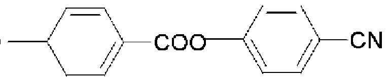 [Chemistry Figure 3]

[3] The retardation film as claimed in claim 1, wherein a material of the oriented retardation film is one or more of those selected from the group consisting of triacetyl cellulose, polyethylene terephtalate, polymethyl methacrylate, polycarbonate, polyethylene and cycloolefin polymer such as norbornene derivatives, polyvinyl alcohol, diacetyl cellulose, polyether sulfone.
[4] A polarizing film wherein the retardation film of any one of claims 1 to 3 is attached on a polarizing plate and located between the polarizing plate and a liquid crystal cell.
[5] A polarizing film wherein the retardation film of any one of claims 1 to 3 is directly attached on one side of a polarizing element adjacent to a liquid crystal cell and located between the polarizing element and the liquid crystal cell.
[6] An IPS mode liquid crystal display including the polarizing film of claim 4.
[7] An IPS mode liquid crystal display including the polarizing film of claim 4.
[8] A method for preparing a retardation film, comprising a step of preparing a retardation film in which a homeotropic alignment liquid crystal film is formed by coating, drying and UV light radiating a polymerizable liquid crystal mixed solution containing a surfactant and a reactive liquid crystal monomer on a surface of an oriented retardation film of which surface is treated to be hy- drophilic, so that the oriented retardation film and the homeotropic alignment liquid crystal film are integrated.
[9] A method for preparing a retardation film, comprising the steps of: preparing a homeotropic alignment liquid crystal film by coating, drying and UV light radiating a solution containing a surfactant and a polymerizable reactive liquid crystal monomer on a plastic substrate of which surface is treated to be hy- drophilic; and attaching an oriented retardation film on the homeotropic alignment liquid crystal film using an adhesive such that they are integrated.
[10] A method for preparing a polarizing film, comprising a step of attaching a retardation film prepared through a method of claim 8 or 9 on one surface of a liquid crystal cell adjacent to a polarizing element or polarizing plate.
Priority Applications (1)
| Application Number | Priority Date | Filing Date | Title |
|---|---|---|---|
| JP2007503848A JP2007522533A (en) | 2005-02-16 | 2006-02-08 | Retardation film including vertically aligned liquid crystal film and method for producing the same |
Applications Claiming Priority (2)
| Application Number | Priority Date | Filing Date | Title |
|---|---|---|---|
| KR10-2005-0012815 | 2005-02-16 | ||
| KR20050012815 | 2005-02-16 |
Publications (1)
| Publication Number | Publication Date |
|---|---|
| WO2006088296A1 true WO2006088296A1 (en) | 2006-08-24 |
Family
ID=36815971
Family Applications (1)
| Application Number | Title | Priority Date | Filing Date |
|---|---|---|---|
| PCT/KR2006/000455 Ceased WO2006088296A1 (en) | 2005-02-16 | 2006-02-08 | Retardation film having a homeotropic alignment liquid crystal film and method for preparing the same |
Country Status (6)
| Country | Link |
|---|---|
| US (1) | US7807235B2 (en) |
| JP (1) | JP2007522533A (en) |
| KR (1) | KR100732325B1 (en) |
| CN (1) | CN100424565C (en) |
| TW (1) | TWI356246B (en) |
| WO (1) | WO2006088296A1 (en) |
Cited By (1)
| Publication number | Priority date | Publication date | Assignee | Title |
|---|---|---|---|---|
| JP2008076984A (en) * | 2006-09-25 | 2008-04-03 | Seiko Epson Corp | Optical characteristic evaluation apparatus and liquid crystal device manufacturing method |
Families Citing this family (37)
| Publication number | Priority date | Publication date | Assignee | Title |
|---|---|---|---|---|
| JP4720634B2 (en) * | 2006-06-13 | 2011-07-13 | ソニー株式会社 | Polymerizable liquid crystal composition, optical element, method for producing optical element, and liquid crystal display device |
| JP4915523B2 (en) * | 2006-06-29 | 2012-04-11 | Jnc株式会社 | Polymerizable liquid crystal composition |
| WO2008052376A1 (en) * | 2006-11-03 | 2008-05-08 | Rolic Ag | Birefringent layer of c-plate and o-plate type |
| JP5002276B2 (en) * | 2007-01-30 | 2012-08-15 | 富士フイルム株式会社 | Liquid crystal display |
| JP5206066B2 (en) * | 2007-03-28 | 2013-06-12 | Jnc株式会社 | Polymerizable liquid crystal composition |
| US20090147192A1 (en) * | 2007-12-05 | 2009-06-11 | Sony Corporation | Liquid crystal display device and a method of manufacturing the same |
| JP5124027B2 (en) * | 2008-01-18 | 2013-01-23 | エルジー・ケム・リミテッド | Optical film, method for producing the same, and liquid crystal display device including the same |
| JP5454084B2 (en) * | 2008-12-16 | 2014-03-26 | Jnc株式会社 | Polymerizable liquid crystal composition and homeotropic alignment liquid crystal film |
| KR101056683B1 (en) * | 2009-01-19 | 2011-08-12 | 주식회사 엘지화학 | Optical film, manufacturing method thereof, and liquid crystal display device comprising the same |
| KR101155575B1 (en) * | 2010-05-12 | 2012-06-19 | 경희대학교 산학협력단 | A manufacturing method of optical film having planar oriented cholesteric liquid crystal layer |
| KR20120005711A (en) * | 2010-07-09 | 2012-01-17 | 동우 화인켐 주식회사 | Polarized glasses |
| JP6029246B2 (en) * | 2011-11-17 | 2016-11-24 | エルジー・ケム・リミテッド | Optical element and stereoscopic image display apparatus including the same |
| CN102634348B (en) * | 2012-03-21 | 2014-06-25 | 广东东邦科技有限公司 | Mixed liquid crystal solution, liquid crystal visual angle enlarging film, preparation method of liquid crystal visual angle enlarging film and liquid crystal display device |
| JP2014028916A (en) | 2012-06-27 | 2014-02-13 | Jnc Corp | Polymerizable liquid crystal composition |
| KR101966726B1 (en) * | 2012-09-05 | 2019-04-08 | 엘지디스플레이 주식회사 | Image display device |
| KR101337005B1 (en) * | 2013-03-29 | 2013-12-04 | 제일모직주식회사 | Protective film for polarizing plate, polarizing plate comprising the same and liquid crystal display comprising the same |
| JP6107441B2 (en) * | 2013-06-06 | 2017-04-05 | Jnc株式会社 | Liquid crystal compound, liquid crystal composition and polymer thereof |
| KR102040796B1 (en) * | 2013-07-17 | 2019-11-05 | 동우 화인켐 주식회사 | A retardation film and display device comprising the same |
| KR102040797B1 (en) * | 2013-07-31 | 2019-11-05 | 동우 화인켐 주식회사 | A retardation film and display device comprising the same |
| TWI574088B (en) | 2013-10-01 | 2017-03-11 | Lg化學股份有限公司 | Optical film,complex polarizing plate and liquid crystal display |
| KR102103497B1 (en) | 2013-11-12 | 2020-04-23 | 삼성전자주식회사 | Retardation film and optical film and display device |
| KR102103498B1 (en) | 2013-11-12 | 2020-04-23 | 삼성전자주식회사 | Retardation film and optical film and display device |
| JP6199716B2 (en) * | 2013-12-02 | 2017-09-20 | 富士フイルム株式会社 | Retardation film and liquid crystal display device |
| KR102407519B1 (en) * | 2013-12-05 | 2022-06-13 | 스미또모 가가꾸 가부시키가이샤 | Optical anisotropic film |
| JP6223215B2 (en) * | 2014-01-31 | 2017-11-01 | 日東電工株式会社 | Method for producing photoresponsive cross-linked liquid crystal polymer film and photoresponsive cross-linked liquid crystal polymer film obtained by the production method |
| JP6648438B2 (en) | 2014-08-27 | 2020-02-14 | Jnc株式会社 | Liquid crystal compound, liquid crystal composition and polymer thereof |
| KR102422667B1 (en) * | 2014-12-26 | 2022-07-18 | 삼성전자주식회사 | Composition for optical film and films and display device |
| KR20160106513A (en) | 2015-03-02 | 2016-09-12 | 제이엔씨 주식회사 | Polymerizable liquid crystal composition and optically anisotropic film |
| KR20160118131A (en) | 2015-04-01 | 2016-10-11 | 제이엔씨 주식회사 | Production method for optical compensation film |
| US10526539B2 (en) | 2015-06-17 | 2020-01-07 | Jnc Corporation | Polymerizable liquid crystal composition and optical anisotropical body thereof |
| JP6733328B2 (en) | 2015-06-17 | 2020-07-29 | Jnc株式会社 | Polymerizable liquid crystal composition and optically anisotropic substance |
| KR20170074178A (en) | 2015-12-21 | 2017-06-29 | 제이엔씨 주식회사 | Polymerizable liquid crystal compound, composition, liquid crystal polymerized film-kinds thereof and use thereof |
| WO2018047707A1 (en) * | 2016-09-06 | 2018-03-15 | 学校法人慶應義塾 | Method for measuring ultraviolet protection effect or infrared protection effect of aqueous composition containing ultraviolet absorbing agent or infrared blocking agent, and apparatus for preparing measurement sample |
| JP6937169B2 (en) * | 2017-06-09 | 2021-09-22 | 日東電工株式会社 | Polarizing plate with retardation layer and image display device |
| KR102383293B1 (en) * | 2018-01-25 | 2022-04-05 | 주식회사 엘지화학 | Multi-layer liquid crystal film, polarizing plate and method for manufacturing of polarizing plate |
| TWI791853B (en) * | 2018-07-03 | 2023-02-11 | 日商Dic股份有限公司 | Substrate and liquid crystal display element |
| TWI814843B (en) * | 2018-07-03 | 2023-09-11 | 日商Dic股份有限公司 | Manufacturing method of liquid crystal display element |
Citations (4)
| Publication number | Priority date | Publication date | Assignee | Title |
|---|---|---|---|---|
| JP2000227520A (en) * | 1999-02-08 | 2000-08-15 | Nitto Denko Corp | Phase difference plate, laminated polarizing plate and liquid crystal display |
| JP2002174725A (en) * | 2000-12-06 | 2002-06-21 | Nitto Denko Corp | Method for producing homeotropically aligned liquid crystal film and homeotropically aligned liquid crystal film |
| JP2002296424A (en) * | 2000-12-18 | 2002-10-09 | Nippon Kayaku Co Ltd | Optical film, polarizing film and method for improving visibility angle of polarizing film |
| JP2003149441A (en) * | 2001-11-15 | 2003-05-21 | Nitto Denko Corp | Retardation plate, method for producing the same, and optical film |
Family Cites Families (16)
| Publication number | Priority date | Publication date | Assignee | Title |
|---|---|---|---|---|
| JPH06148429A (en) * | 1992-11-04 | 1994-05-27 | Sumitomo Chem Co Ltd | Production of composite phase difference film |
| DE69405620T2 (en) * | 1993-03-25 | 1998-04-23 | Sumitomo Chemical Co | Optical anisotropic material, method of manufacture, retardation plate and liquid crystal display using it |
| JP3284002B2 (en) * | 1993-11-22 | 2002-05-20 | 富士写真フイルム株式会社 | Elliptical polarizing plate and liquid crystal display device using the same |
| JP3204182B2 (en) | 1997-10-24 | 2001-09-04 | 日本電気株式会社 | In-plane switching LCD |
| JP3810969B2 (en) | 1999-12-06 | 2006-08-16 | 日東電工株式会社 | Optical compensation polarizing plate and manufacturing method of liquid crystal display device |
| KR100378529B1 (en) | 2000-11-09 | 2003-03-31 | 엘지전선 주식회사 | Fabrication of Quarter-wave Films Using a Liquid Crystal and Application to the CLC Polarizer |
| KR100883004B1 (en) * | 2000-11-23 | 2009-02-12 | 메르크 파텐트 게엠베하 | Homeotropic alignment floor |
| US6885423B2 (en) * | 2000-12-06 | 2005-04-26 | Nitto Denko Corporation | Method for manufacturing homeotropic alignment liquid crystal film |
| CA2678208A1 (en) * | 2000-12-18 | 2002-06-27 | Nippon Kayaku Kabushiki Kaisha | Optical film and polarizing film using the same, and method for improving view angle of the polarizing film |
| CN100394225C (en) * | 2000-12-18 | 2008-06-11 | 日本化药株式会社 | Optical film, polarizing film using same, and method for improving viewing angle of polarizing film |
| JP2003121642A (en) | 2001-10-10 | 2003-04-23 | Nitto Denko Corp | Wide viewing angle polarizer and liquid crystal display |
| JP2004029062A (en) * | 2002-06-21 | 2004-01-29 | Nippon Kayaku Co Ltd | Liquid crystal composition and liquid crystal phase difference film using the same |
| KR20050108351A (en) * | 2003-02-12 | 2005-11-16 | 니폰 가야꾸 가부시끼가이샤 | Substrate for vertical alignment and process for producing vertically aligned liquid crystal retardation film |
| JP2004287416A (en) * | 2003-03-06 | 2004-10-14 | Nitto Denko Corp | Method for producing tilted oriented film, tilted oriented film, and image display device using the same |
| JP2005070096A (en) | 2003-08-25 | 2005-03-17 | Sumitomo Chemical Co Ltd | Retardation plate integrated polarizing plate, manufacturing method thereof, and liquid crystal display device |
| CN101010269B (en) * | 2004-12-11 | 2011-12-07 | Lg化学株式会社 | A homeotropic alignment liquid crystal film without alignment layer and method for preparing the same |
-
2006
- 2006-01-20 KR KR1020060006398A patent/KR100732325B1/en not_active Expired - Lifetime
- 2006-02-08 WO PCT/KR2006/000455 patent/WO2006088296A1/en not_active Ceased
- 2006-02-08 CN CNB2006800000679A patent/CN100424565C/en not_active Expired - Lifetime
- 2006-02-08 JP JP2007503848A patent/JP2007522533A/en active Pending
- 2006-02-14 US US11/353,226 patent/US7807235B2/en active Active
- 2006-02-14 TW TW095104962A patent/TWI356246B/en not_active IP Right Cessation
Patent Citations (4)
| Publication number | Priority date | Publication date | Assignee | Title |
|---|---|---|---|---|
| JP2000227520A (en) * | 1999-02-08 | 2000-08-15 | Nitto Denko Corp | Phase difference plate, laminated polarizing plate and liquid crystal display |
| JP2002174725A (en) * | 2000-12-06 | 2002-06-21 | Nitto Denko Corp | Method for producing homeotropically aligned liquid crystal film and homeotropically aligned liquid crystal film |
| JP2002296424A (en) * | 2000-12-18 | 2002-10-09 | Nippon Kayaku Co Ltd | Optical film, polarizing film and method for improving visibility angle of polarizing film |
| JP2003149441A (en) * | 2001-11-15 | 2003-05-21 | Nitto Denko Corp | Retardation plate, method for producing the same, and optical film |
Cited By (1)
| Publication number | Priority date | Publication date | Assignee | Title |
|---|---|---|---|---|
| JP2008076984A (en) * | 2006-09-25 | 2008-04-03 | Seiko Epson Corp | Optical characteristic evaluation apparatus and liquid crystal device manufacturing method |
Also Published As
| Publication number | Publication date |
|---|---|
| TW200632477A (en) | 2006-09-16 |
| TWI356246B (en) | 2012-01-11 |
| CN1942813A (en) | 2007-04-04 |
| JP2007522533A (en) | 2007-08-09 |
| CN100424565C (en) | 2008-10-08 |
| KR100732325B1 (en) | 2007-06-25 |
| KR20060092048A (en) | 2006-08-22 |
| US7807235B2 (en) | 2010-10-05 |
| US20060182900A1 (en) | 2006-08-17 |
Similar Documents
| Publication | Publication Date | Title |
|---|---|---|
| US7807235B2 (en) | Retardation film having a homeotropic alignment liquid crystal film | |
| US7283188B2 (en) | Compensator comprising a positive and negative birefringent retardation film | |
| JP5154945B2 (en) | Homeotropic alignment liquid crystal film which does not require alignment film and method for producing the same | |
| US8134666B2 (en) | Liquid crystal display device | |
| US20060103796A1 (en) | Elliptically polarizing plate and image display apparatus using the same | |
| US7169447B2 (en) | Achromatic quarter wave film | |
| WO2008059721A1 (en) | Elliptic polarizing plate and vertically aligned liquid crystal display using the same | |
| CA2678208A1 (en) | Optical film and polarizing film using the same, and method for improving view angle of the polarizing film | |
| WO2006085454A1 (en) | Homeotropically oriented liquid-crystal film, optical film comprising the same, and image display | |
| US20060203158A1 (en) | Compensated lcd of the ips mode | |
| WO2005116741A1 (en) | Liquid crystal display | |
| WO2009028429A1 (en) | Elliptically polarizing plate, method for producing the same, and liquid crystal display device using the same | |
| JP4388023B2 (en) | Polarizing plate with optical compensation layer, liquid crystal panel using polarizing plate with optical compensation layer, liquid crystal display device, and image display device | |
| JP2009288440A (en) | Retardation film, method for manufacturing retardation film, polarizing plate, and liquid crystal display | |
| WO2008105218A1 (en) | Elliptical polarizing plate for vertically aligned liquid crystal display and vertically aligned liquid crystal display using the same | |
| US20070064177A1 (en) | Liquid crystal display device | |
| JP2007072213A (en) | Viewing angle compensation plate for vertical alignment type liquid crystal display device and vertical alignment type liquid crystal display device using the same | |
| EP1363156A2 (en) | Optical compensator for a liquid crystal display employing a positive and a negative birefringent retardation film | |
| WO2025022978A1 (en) | Viewing angle control system and image display device | |
| JP2007286331A (en) | Optical compensation sheet, and polarizing plate and liquid crystal display device using the same | |
| WO2024135354A1 (en) | Laminate, liquid crystal display device, and in-vehicle display | |
| JP2007286235A (en) | Liquid crystal panel and liquid crystal display device |
Legal Events
| Date | Code | Title | Description |
|---|---|---|---|
| WWE | Wipo information: entry into national phase |
Ref document number: 2007503848 Country of ref document: JP |
|
| WWE | Wipo information: entry into national phase |
Ref document number: 200680000067.9 Country of ref document: CN |
|
| 121 | Ep: the epo has been informed by wipo that ep was designated in this application | ||
| NENP | Non-entry into the national phase |
Ref country code: DE |
|
| 122 | Ep: pct application non-entry in european phase |
Ref document number: 06715907 Country of ref document: EP Kind code of ref document: A1 |