WO2006043363A1 - Oxygen-permeable film, oxygen-permeable sheet and electric cell comprising the same - Google Patents
Oxygen-permeable film, oxygen-permeable sheet and electric cell comprising the same Download PDFInfo
- Publication number
- WO2006043363A1 WO2006043363A1 PCT/JP2005/014578 JP2005014578W WO2006043363A1 WO 2006043363 A1 WO2006043363 A1 WO 2006043363A1 JP 2005014578 W JP2005014578 W JP 2005014578W WO 2006043363 A1 WO2006043363 A1 WO 2006043363A1
- Authority
- WO
- WIPO (PCT)
- Prior art keywords
- oxygen
- particles
- membrane
- air
- polytetrafluoroethylene
- Prior art date
Links
Classifications
-
- H—ELECTRICITY
- H01—ELECTRIC ELEMENTS
- H01M—PROCESSES OR MEANS, e.g. BATTERIES, FOR THE DIRECT CONVERSION OF CHEMICAL ENERGY INTO ELECTRICAL ENERGY
- H01M50/00—Constructional details or processes of manufacture of the non-active parts of electrochemical cells other than fuel cells, e.g. hybrid cells
- H01M50/40—Separators; Membranes; Diaphragms; Spacing elements inside cells
- H01M50/489—Separators, membranes, diaphragms or spacing elements inside the cells, characterised by their physical properties, e.g. swelling degree, hydrophilicity or shut down properties
-
- H—ELECTRICITY
- H01—ELECTRIC ELEMENTS
- H01M—PROCESSES OR MEANS, e.g. BATTERIES, FOR THE DIRECT CONVERSION OF CHEMICAL ENERGY INTO ELECTRICAL ENERGY
- H01M4/00—Electrodes
- H01M4/86—Inert electrodes with catalytic activity, e.g. for fuel cells
- H01M4/8605—Porous electrodes
-
- H—ELECTRICITY
- H01—ELECTRIC ELEMENTS
- H01M—PROCESSES OR MEANS, e.g. BATTERIES, FOR THE DIRECT CONVERSION OF CHEMICAL ENERGY INTO ELECTRICAL ENERGY
- H01M12/00—Hybrid cells; Manufacture thereof
- H01M12/04—Hybrid cells; Manufacture thereof composed of a half-cell of the fuel-cell type and of a half-cell of the primary-cell type
- H01M12/06—Hybrid cells; Manufacture thereof composed of a half-cell of the fuel-cell type and of a half-cell of the primary-cell type with one metallic and one gaseous electrode
-
- H—ELECTRICITY
- H01—ELECTRIC ELEMENTS
- H01M—PROCESSES OR MEANS, e.g. BATTERIES, FOR THE DIRECT CONVERSION OF CHEMICAL ENERGY INTO ELECTRICAL ENERGY
- H01M50/00—Constructional details or processes of manufacture of the non-active parts of electrochemical cells other than fuel cells, e.g. hybrid cells
- H01M50/40—Separators; Membranes; Diaphragms; Spacing elements inside cells
- H01M50/409—Separators, membranes or diaphragms characterised by the material
- H01M50/411—Organic material
- H01M50/414—Synthetic resins, e.g. thermoplastics or thermosetting resins
- H01M50/426—Fluorocarbon polymers
-
- H—ELECTRICITY
- H01—ELECTRIC ELEMENTS
- H01M—PROCESSES OR MEANS, e.g. BATTERIES, FOR THE DIRECT CONVERSION OF CHEMICAL ENERGY INTO ELECTRICAL ENERGY
- H01M50/00—Constructional details or processes of manufacture of the non-active parts of electrochemical cells other than fuel cells, e.g. hybrid cells
- H01M50/40—Separators; Membranes; Diaphragms; Spacing elements inside cells
- H01M50/409—Separators, membranes or diaphragms characterised by the material
- H01M50/431—Inorganic material
-
- H—ELECTRICITY
- H01—ELECTRIC ELEMENTS
- H01M—PROCESSES OR MEANS, e.g. BATTERIES, FOR THE DIRECT CONVERSION OF CHEMICAL ENERGY INTO ELECTRICAL ENERGY
- H01M50/00—Constructional details or processes of manufacture of the non-active parts of electrochemical cells other than fuel cells, e.g. hybrid cells
- H01M50/40—Separators; Membranes; Diaphragms; Spacing elements inside cells
- H01M50/409—Separators, membranes or diaphragms characterised by the material
- H01M50/443—Particulate material
-
- H—ELECTRICITY
- H01—ELECTRIC ELEMENTS
- H01M—PROCESSES OR MEANS, e.g. BATTERIES, FOR THE DIRECT CONVERSION OF CHEMICAL ENERGY INTO ELECTRICAL ENERGY
- H01M50/00—Constructional details or processes of manufacture of the non-active parts of electrochemical cells other than fuel cells, e.g. hybrid cells
- H01M50/40—Separators; Membranes; Diaphragms; Spacing elements inside cells
- H01M50/409—Separators, membranes or diaphragms characterised by the material
- H01M50/449—Separators, membranes or diaphragms characterised by the material having a layered structure
- H01M50/457—Separators, membranes or diaphragms characterised by the material having a layered structure comprising three or more layers
-
- H—ELECTRICITY
- H01—ELECTRIC ELEMENTS
- H01M—PROCESSES OR MEANS, e.g. BATTERIES, FOR THE DIRECT CONVERSION OF CHEMICAL ENERGY INTO ELECTRICAL ENERGY
- H01M50/00—Constructional details or processes of manufacture of the non-active parts of electrochemical cells other than fuel cells, e.g. hybrid cells
- H01M50/40—Separators; Membranes; Diaphragms; Spacing elements inside cells
- H01M50/463—Separators, membranes or diaphragms characterised by their shape
-
- H—ELECTRICITY
- H01—ELECTRIC ELEMENTS
- H01M—PROCESSES OR MEANS, e.g. BATTERIES, FOR THE DIRECT CONVERSION OF CHEMICAL ENERGY INTO ELECTRICAL ENERGY
- H01M50/00—Constructional details or processes of manufacture of the non-active parts of electrochemical cells other than fuel cells, e.g. hybrid cells
- H01M50/40—Separators; Membranes; Diaphragms; Spacing elements inside cells
- H01M50/489—Separators, membranes, diaphragms or spacing elements inside the cells, characterised by their physical properties, e.g. swelling degree, hydrophilicity or shut down properties
- H01M50/491—Porosity
-
- H—ELECTRICITY
- H01—ELECTRIC ELEMENTS
- H01M—PROCESSES OR MEANS, e.g. BATTERIES, FOR THE DIRECT CONVERSION OF CHEMICAL ENERGY INTO ELECTRICAL ENERGY
- H01M8/00—Fuel cells; Manufacture thereof
- H01M8/02—Details
- H01M8/0202—Collectors; Separators, e.g. bipolar separators; Interconnectors
- H01M8/023—Porous and characterised by the material
- H01M8/0232—Metals or alloys
-
- H—ELECTRICITY
- H01—ELECTRIC ELEMENTS
- H01M—PROCESSES OR MEANS, e.g. BATTERIES, FOR THE DIRECT CONVERSION OF CHEMICAL ENERGY INTO ELECTRICAL ENERGY
- H01M8/00—Fuel cells; Manufacture thereof
- H01M8/02—Details
- H01M8/0202—Collectors; Separators, e.g. bipolar separators; Interconnectors
- H01M8/023—Porous and characterised by the material
- H01M8/0239—Organic resins; Organic polymers
-
- H—ELECTRICITY
- H01—ELECTRIC ELEMENTS
- H01M—PROCESSES OR MEANS, e.g. BATTERIES, FOR THE DIRECT CONVERSION OF CHEMICAL ENERGY INTO ELECTRICAL ENERGY
- H01M8/00—Fuel cells; Manufacture thereof
- H01M8/02—Details
- H01M8/0202—Collectors; Separators, e.g. bipolar separators; Interconnectors
- H01M8/023—Porous and characterised by the material
- H01M8/0241—Composites
- H01M8/0245—Composites in the form of layered or coated products
-
- H—ELECTRICITY
- H01—ELECTRIC ELEMENTS
- H01M—PROCESSES OR MEANS, e.g. BATTERIES, FOR THE DIRECT CONVERSION OF CHEMICAL ENERGY INTO ELECTRICAL ENERGY
- H01M8/00—Fuel cells; Manufacture thereof
- H01M8/02—Details
- H01M8/0202—Collectors; Separators, e.g. bipolar separators; Interconnectors
- H01M8/0247—Collectors; Separators, e.g. bipolar separators; Interconnectors characterised by the form
-
- H—ELECTRICITY
- H01—ELECTRIC ELEMENTS
- H01M—PROCESSES OR MEANS, e.g. BATTERIES, FOR THE DIRECT CONVERSION OF CHEMICAL ENERGY INTO ELECTRICAL ENERGY
- H01M8/00—Fuel cells; Manufacture thereof
- H01M8/04—Auxiliary arrangements, e.g. for control of pressure or for circulation of fluids
- H01M8/04082—Arrangements for control of reactant parameters, e.g. pressure or concentration
- H01M8/04089—Arrangements for control of reactant parameters, e.g. pressure or concentration of gaseous reactants
- H01M8/04119—Arrangements for control of reactant parameters, e.g. pressure or concentration of gaseous reactants with simultaneous supply or evacuation of electrolyte; Humidifying or dehumidifying
- H01M8/04156—Arrangements for control of reactant parameters, e.g. pressure or concentration of gaseous reactants with simultaneous supply or evacuation of electrolyte; Humidifying or dehumidifying with product water removal
- H01M8/04171—Arrangements for control of reactant parameters, e.g. pressure or concentration of gaseous reactants with simultaneous supply or evacuation of electrolyte; Humidifying or dehumidifying with product water removal using adsorbents, wicks or hydrophilic material
-
- H—ELECTRICITY
- H01—ELECTRIC ELEMENTS
- H01M—PROCESSES OR MEANS, e.g. BATTERIES, FOR THE DIRECT CONVERSION OF CHEMICAL ENERGY INTO ELECTRICAL ENERGY
- H01M8/00—Fuel cells; Manufacture thereof
- H01M8/10—Fuel cells with solid electrolytes
-
- Y—GENERAL TAGGING OF NEW TECHNOLOGICAL DEVELOPMENTS; GENERAL TAGGING OF CROSS-SECTIONAL TECHNOLOGIES SPANNING OVER SEVERAL SECTIONS OF THE IPC; TECHNICAL SUBJECTS COVERED BY FORMER USPC CROSS-REFERENCE ART COLLECTIONS [XRACs] AND DIGESTS
- Y02—TECHNOLOGIES OR APPLICATIONS FOR MITIGATION OR ADAPTATION AGAINST CLIMATE CHANGE
- Y02E—REDUCTION OF GREENHOUSE GAS [GHG] EMISSIONS, RELATED TO ENERGY GENERATION, TRANSMISSION OR DISTRIBUTION
- Y02E60/00—Enabling technologies; Technologies with a potential or indirect contribution to GHG emissions mitigation
- Y02E60/10—Energy storage using batteries
-
- Y—GENERAL TAGGING OF NEW TECHNOLOGICAL DEVELOPMENTS; GENERAL TAGGING OF CROSS-SECTIONAL TECHNOLOGIES SPANNING OVER SEVERAL SECTIONS OF THE IPC; TECHNICAL SUBJECTS COVERED BY FORMER USPC CROSS-REFERENCE ART COLLECTIONS [XRACs] AND DIGESTS
- Y02—TECHNOLOGIES OR APPLICATIONS FOR MITIGATION OR ADAPTATION AGAINST CLIMATE CHANGE
- Y02E—REDUCTION OF GREENHOUSE GAS [GHG] EMISSIONS, RELATED TO ENERGY GENERATION, TRANSMISSION OR DISTRIBUTION
- Y02E60/00—Enabling technologies; Technologies with a potential or indirect contribution to GHG emissions mitigation
- Y02E60/30—Hydrogen technology
- Y02E60/50—Fuel cells
-
- Y—GENERAL TAGGING OF NEW TECHNOLOGICAL DEVELOPMENTS; GENERAL TAGGING OF CROSS-SECTIONAL TECHNOLOGIES SPANNING OVER SEVERAL SECTIONS OF THE IPC; TECHNICAL SUBJECTS COVERED BY FORMER USPC CROSS-REFERENCE ART COLLECTIONS [XRACs] AND DIGESTS
- Y10—TECHNICAL SUBJECTS COVERED BY FORMER USPC
- Y10T—TECHNICAL SUBJECTS COVERED BY FORMER US CLASSIFICATION
- Y10T428/00—Stock material or miscellaneous articles
- Y10T428/24—Structurally defined web or sheet [e.g., overall dimension, etc.]
- Y10T428/24273—Structurally defined web or sheet [e.g., overall dimension, etc.] including aperture
- Y10T428/24322—Composite web or sheet
- Y10T428/24331—Composite web or sheet including nonapertured component
-
- Y—GENERAL TAGGING OF NEW TECHNOLOGICAL DEVELOPMENTS; GENERAL TAGGING OF CROSS-SECTIONAL TECHNOLOGIES SPANNING OVER SEVERAL SECTIONS OF THE IPC; TECHNICAL SUBJECTS COVERED BY FORMER USPC CROSS-REFERENCE ART COLLECTIONS [XRACs] AND DIGESTS
- Y10—TECHNICAL SUBJECTS COVERED BY FORMER USPC
- Y10T—TECHNICAL SUBJECTS COVERED BY FORMER US CLASSIFICATION
- Y10T428/00—Stock material or miscellaneous articles
- Y10T428/249921—Web or sheet containing structurally defined element or component
- Y10T428/249953—Composite having voids in a component [e.g., porous, cellular, etc.]
- Y10T428/249981—Plural void-containing components
-
- Y—GENERAL TAGGING OF NEW TECHNOLOGICAL DEVELOPMENTS; GENERAL TAGGING OF CROSS-SECTIONAL TECHNOLOGIES SPANNING OVER SEVERAL SECTIONS OF THE IPC; TECHNICAL SUBJECTS COVERED BY FORMER USPC CROSS-REFERENCE ART COLLECTIONS [XRACs] AND DIGESTS
- Y10—TECHNICAL SUBJECTS COVERED BY FORMER USPC
- Y10T—TECHNICAL SUBJECTS COVERED BY FORMER US CLASSIFICATION
- Y10T428/00—Stock material or miscellaneous articles
- Y10T428/25—Web or sheet containing structurally defined element or component and including a second component containing structurally defined particles
- Y10T428/254—Polymeric or resinous material
-
- Y—GENERAL TAGGING OF NEW TECHNOLOGICAL DEVELOPMENTS; GENERAL TAGGING OF CROSS-SECTIONAL TECHNOLOGIES SPANNING OVER SEVERAL SECTIONS OF THE IPC; TECHNICAL SUBJECTS COVERED BY FORMER USPC CROSS-REFERENCE ART COLLECTIONS [XRACs] AND DIGESTS
- Y10—TECHNICAL SUBJECTS COVERED BY FORMER USPC
- Y10T—TECHNICAL SUBJECTS COVERED BY FORMER US CLASSIFICATION
- Y10T442/00—Fabric [woven, knitted, or nonwoven textile or cloth, etc.]
- Y10T442/10—Scrim [e.g., open net or mesh, gauze, loose or open weave or knit, etc.]
-
- Y—GENERAL TAGGING OF NEW TECHNOLOGICAL DEVELOPMENTS; GENERAL TAGGING OF CROSS-SECTIONAL TECHNOLOGIES SPANNING OVER SEVERAL SECTIONS OF THE IPC; TECHNICAL SUBJECTS COVERED BY FORMER USPC CROSS-REFERENCE ART COLLECTIONS [XRACs] AND DIGESTS
- Y10—TECHNICAL SUBJECTS COVERED BY FORMER USPC
- Y10T—TECHNICAL SUBJECTS COVERED BY FORMER US CLASSIFICATION
- Y10T442/00—Fabric [woven, knitted, or nonwoven textile or cloth, etc.]
- Y10T442/60—Nonwoven fabric [i.e., nonwoven strand or fiber material]
Definitions
- the present invention relates generally to an oxygen permeable membrane, and more particularly, to a membrane that selectively permeates oxygen while suppressing permeation of water vapor.
- the oxygen permeable membrane is applied to, for example, an air (oxygen) intake mechanism of an air cell or fuel cell which takes in oxygen in the atmosphere.
- the present invention relates to an air purification membrane for removing atmospheric water vapor.
- Patent Document 2 an air battery has been proposed in which a plurality of transmission holes of 300 ⁇ m or less for passing air through a uniform film or the like are provided as a selective transmission film that suppresses the transmission of water vapor.
- Non-patent Document 1 PTFE (polytetrafluoroethylene) particles to the surface of the antenna using a binder as a low snowfall material
- Patent Document 1 Japanese Patent Application Laid-Open No. 59-75582
- Patent Document 2 Japanese Patent Application Laid-Open No. 6-44954
- Non-Patent Document 1 Super-hydrophilic ⁇ Super-water-repellent technology, published by Japan Technical Information Association, p. 155- 163 Disclosure of the invention
- the present inventors have obtained the following findings. That is, when the gas permeable membrane is made of predetermined particles and the super water repellent state (the contact angle with water is 120 ° C. or more), the air permeates the gas permeable membrane. However, we found that water vapor permeation was suppressed.
- molecules other than water vapor in the air such as oxygen and nitrogen, do not receive a large repulsive force even when they collide with the membrane surface or the inner wall of the pore, so they can diffuse (pass) through the pore. .
- the present invention proposes an oxygen permeable membrane composed of an aggregate of water repellent particles.
- the oxygen-permeable membrane of the present invention has an antenna surface as proposed by Non-Patent Document 1 Unlike the composite of the binder and the PTFE particles, which is applied without any gap on the surface, it is permeable to oxygen.
- the oxygen permeable membrane of the present invention is composed entirely or almost entirely of water repellent particle cages, the membrane surface and the inner wall of pores in the membrane have a large number of irregularities. By such unevenness, the water repellency of the film is enhanced, and a super water repellent state in which the contact angle with water is 120 ° or more is realized. Therefore, when the air passes through the oxygen permeable membrane of the present invention, the permeation of water vapor is suppressed.
- the oxygen-permeable membrane of the present invention is produced by bonding particles having an average particle diameter of 0.01 to 50 ⁇ m and having water repellency by various methods.
- an aggregate of particles fused and integrated by heating or the like can be used as an oxygen permeable membrane.
- the physical properties of the film can be controlled by changing the type of particles constituting the film, the particle size, the bonding method between particles, and the like.
- fluorine resin For particles having water repellency, it is desirable to use a fluorine resin.
- fluorine resin As fluorine resin
- At least one selected from the group consisting of polytetrafluoroethylene, polyvinyl fluoride and polyvinylidene fluoride is also preferred.
- Oxygen permeable membrane of the present invention has a specific surface area of 0. lm 2 / g or more is desirably not more than 500m 2 / g. Further, the thickness of the oxygen permeable membrane is not particularly limited, but, for example, 0.1 ⁇ m or more 1
- the present invention also comprises an oxygen-permeable sheet comprising the above-mentioned oxygen-permeable membrane and a porous substrate supporting the membrane, and the above-mentioned oxygen-permeable membrane and a pair of porous substrates sandwiching the membrane. It relates to an oxygen permeable sheet having a three-layer structure.
- the Gurley number of the oxygen-permeable sheet is preferably from 0.5 seconds to 50000 seconds.
- At least a group force consisting of polyethylene, polypropylene, polytetrafluoroethylene, vinylon, polytetrafluoroethylene (PPS), polybutylene terephthalate (PBT) and nylon is also selected.
- PPS polytetrafluoroethylene
- PBT polybutylene terephthalate
- the porous substrate desirably has a form of mesh, non-woven fabric or microporous film.
- metal can also be used as the material of the porous substrate. Ie perforated metal A foil or metal mesh can also be used.
- the aggregate of particles having water repellency preferably has pores with a diameter of 0.5 ⁇ m or less.
- integrated pore volume SI in the range of diameter 0. Ol ⁇ m- O 5 m, diameter 0.
- the ratio of accumulated pore volume 32 in the range of 111 to 110 111: 31732 is not less than 0.01,
- the ratio is 0.8 or less, and more preferably 0.02 or more and 0.75 or less. Furthermore, in the oxygen permeable membrane of the present invention having pores having a diameter of 0.5 m or less, the pore porosity is preferably 20% to 90%.
- the present invention further relates to an air battery comprising a positive electrode, a negative electrode and an electrolyte, and having an air intake mechanism for supplying air to the positive electrode, wherein the air intake mechanism comprises the above-mentioned oxygen permeable membrane or oxygen permeable sheet
- An air battery comprising the
- the present invention relates to a fuel cell comprising an air intake mechanism for supplying air to a force sword, which further includes a force source, an anode, and an electrolyte, and the air intake mechanism is any of the above oxygen permeable membranes or oxygen.
- the present invention relates to a fuel cell having a permeable sheet.
- PTFE polytetrafluoroethylene
- an oxygen-permeable membrane which is composed of aggregates of water repellent particles and has an average particle diameter of 0.01 to 50 ⁇ m, can suppress the transmission of water vapor from the air, and therefore it is more dry. Air can be obtained.
- an oxygen permeable membrane By applying such an oxygen permeable membrane to the air intake hole of an air cell or a fuel cell, it is possible to introduce a relatively large amount of oxygen into the cell while suppressing the penetration of water vapor into the cell. Therefore, in the air battery, good high-rate discharge characteristics can be obtained even after storage in the open state.
- fuel cells it is possible to suppress water blockage with a force-sword, and it is possible to expand the allowable operating range.
- the oxygen permeable membrane of the present invention when the oxygen permeable membrane of the present invention is applied to an element or device other than a battery, intrusion of water vapor in the air into the element or device is suppressed. Therefore, the function to prevent the adverse effect of water vapor can be imparted to the element or device. For example, indoors other than water vapor In an apparatus for exchanging air with external air, indoor humidity can be maintained by exchanging indoor air with external air through the oxygen permeable membrane of the present invention.
- the present invention is also applicable to the food related field.
- the oxygen-permeable sheet of the present invention it is possible to suppress the entry of moisture in the air into the food during storage, and it is possible to improve the preservation.
- FIG. 1 is a front view of a cross section of a part of a coin-type air battery provided with an oxygen permeable sheet.
- Fig. 2A is a front view of a cross section of a part of an AA-type air zinc battery provided with an oxygen permeable sheet.
- FIG. 2B is a partially enlarged view of FIG. 2A.
- FIG. 3 A pore size distribution diagram showing the relationship between the pore diameter of the oxygen permeable membrane and the log differential pore volume.
- FIG. 4 is a pore size distribution diagram showing the relationship between the pore diameter of the oxygen permeable membrane and the cumulative pore volume.
- the oxygen-permeable membrane of the present invention contains an aggregate of water-repellent particles, and the average particle diameter of the particles is 0.01 to 50 / ⁇ . A large number of irregularities are formed on the surface of the film and the inner wall of the pores in the film due to the particle shape, and the film is in a state of having super water repellency. Also, the inside of the oxygen permeable membrane is occupied by particles in which parts of the surface are bonded together by fusion or via a binder. Therefore, the inside of the oxygen permeable membrane has a fractal structure and has many voids.
- a film having a contact angle with water of 120 ° or more is defined as having super water repellency.
- the oxygen-permeable membrane of the present invention When the oxygen-permeable membrane of the present invention is disposed, for example, in the air intake path of an air cell or a fuel cell, only water vapor contained in the air is removed when the air passes through the membrane. Dry air is introduced into the battery interior. Therefore, oxygen introduction can be promoted relatively.
- the average particle diameter of the water-repellent particles is larger than 50 m, the unevenness of the film surface and the inner wall of the pores in the film is reduced, so that the effect of repelling water vapor can not be obtained sufficiently.
- the average particle size of the water repellent particles is smaller than 0.01 ⁇ m, the pore diameter in the membrane becomes considerably small, and at the same time it has the effect of suppressing the permeation of water vapor, the permeation of oxygen is also delayed. I will. Therefore, it becomes difficult to obtain the necessary amount of oxygen quickly.
- the average particle diameter of the water repellent particles constituting the oxygen permeable membrane is limited to 0.011 to 50111.
- the contact angle between the membrane and water is desirably 140 ° or more.
- the oxygen-permeable membrane of the present invention may be in a state in which its constituent particles are bound together by a binder, but it is preferable to fuse the particles together by heat treatment etc. without using a binder. .
- the membrane strength becomes strong, and the water vapor permeation suppressing effect can be maintained for a longer time.
- the oxygen-permeable membrane in a state of being bound by a binder may be further heat-treated to fuse the particles together.
- a binder for example, a silicone-based resin is preferred as the noinda, but a fluorine-based resin such as poly (vinyl fluoride) can also be used.
- the amount of the binder depends on the particle diameter of the water repellent particles, etc., and can not be generally specified and is not particularly limited. For example, 2 to 20 parts by weight is used per 100 parts by weight of water repellent particles. It is possible to
- the fluorine resin may, for example, be polytetrafluoroethylene (PTFE), polyethylene trifluoride, ethylene polyfluoride, polybiphenylidene, dichlorodifluoroethylene, polytrichloroethylene, fluoroethylene Propylene copolymer, Perfno Leoroa norekilbi-Nore e tenore polymer, -Furono Leoroanorekil binnore Estenole polymer, ethylene tetrafluoro ethylene copolymer, etc.
- PTFE polytetrafluoroethylene
- polyethylene trifluoride ethylene polyfluoride
- polybiphenylidene dichlorodifluoroethylene
- dichlorodifluoroethylene polytrichloroethylene
- fluoroethylene Propylene copolymer Perfno Leoroa norekilbi-Nore e tenore polymer
- polytetrafluoroethylene, polyvinyl fluoride and polyvinylidene fluoride are particularly preferable because they are particularly excellent in water repellency.
- Polyolefins such as polyethylene and polypropylene, polychlorinated burls, polychlorinated vinylidenes, polyethylene terephthalate, polystyrene and the like can be used as particles having water repellency.
- the specific surface area of the oxygen permeable film of the present invention 0. lm 2 / g or more and 500 meters 2 / g or less.
- the specific surface area exceeds 500 m 2 Zg, the water vapor permeation suppressing effect is enhanced, but the pore diameter in the membrane becomes smaller as a force. Therefore, the permeation rate of oxygen also decreases, which may make it difficult to obtain the required amount of oxygen quickly.
- the specific surface area is smaller than 0.1 lm 2 / g, the oxygen permeation rate will be faster but the water vapor permeation inhibitory effect will be smaller.
- the specific surface area of the membrane is set to lm 2 / g or more and 100 m 2 / g or less.
- the thickness of the oxygen permeable membrane of the present invention is preferably 0.1 m or more and 1000 ⁇ m or less. If the thickness of the membrane is more than 1000 m, the distance through which the gas passes through the membrane will be long, and the effect of suppressing water vapor permeation will be enhanced, but it may be difficult to obtain the necessary amount of oxygen quickly. Conversely, if the thickness of the membrane is less than 0.:Lm, the passage of oxygen will be good, but it will tend to be difficult to form a uniform membrane. If the film becomes uneven, the density difference of water-repellent particles in the film will occur, and the degree of unevenness formed on the film surface and the inner wall of the pores will also be uneven. As a result, the water vapor permeation suppressing effect may be reduced. It is particularly preferable to set the thickness of the membrane to 5 m or more and 500 m or less from the viewpoint of obtaining a uniform membrane having a high oxygen transmission rate.
- the oxygen-permeable membrane of the present invention can also be used by being supported on a porous base material serving as a support or sandwiched between a pair of porous base materials.
- a combination of a support and an oxygen permeable membrane is referred to as an oxygen permeable sheet.
- the oxygen-permeable sheet having a three-layer structure in which the oxygen-permeable membrane is held between a pair of porous substrates, the oxygen-permeable membrane is prevented from being damaged, so the water vapor permeation suppressing effect can be sustained for a long time.
- the porous substrate is not particularly limited as long as it has the ability to pass gas and can support an oxygen permeable membrane. However, it is desirable to use one having an oxygen permeation rate faster than that of the oxygen permeable membrane of the present invention so that the movement of oxygen passing through the oxygen permeable membrane is not unnecessarily restricted.
- the material of the porous substrate is, for example, polytetrafluoroethylene (PTFE), polypropylene (PP), polyethylene (PE), vinylon, polytetrafluoroethylene (PPS), polyethylene terephthalate (PBT) , Vinylon, nylon and the like.
- PTFE polytetrafluoroethylene
- PP polypropylene
- PE polyethylene
- PPS polytetrafluoroethylene
- PBT polyethylene terephthalate
- Vinylon nylon and the like.
- the porous substrate desirably has a form of mesh or non-woven fabric.
- the porous substrate may also have the form of a microporous membrane.
- a microporous film for example, a porous resin sheet or a film obtained by drawing the same, a porous resin sheet containing fine particles such as silica, or a resin sheet containing fine particles can be used as a solvent or the like. And the like, and the like.
- a metal base such as a perforated metal foil or metal mesh can also be used as the porous base.
- the film strength can be controlled relatively easily by the thickness of the substrate, the degree of perforation, the porosity and the like.
- the Gurley number of the oxygen permeable membrane of the present invention and the oxygen permeable sheet formed of a porous substrate is preferably 0.5 seconds or more and 50000 seconds or less.
- the Gurley number is larger than 50000 seconds, the water vapor permeation suppressing effect is increased, but it may be difficult to obtain the necessary amount of oxygen quickly.
- the Gurley number is made smaller than 0.5 second, it is necessary to make the thickness of the film thin and thin, and the water vapor permeation suppressing effect in the film tends to be uneven. From the viewpoint of obtaining a uniform film having a high oxygen transmission rate, it is particularly preferable to set the Gurley number of the film to 10 seconds or more and 20000 seconds or less.
- the aggregate of particles having water repellency preferably has pores having a diameter of 0.5 ⁇ m or less.
- the presence of the minute pores further improves the effect of suppressing the permeation of water vapor.
- the size of the pore size of the oxygen permeable membrane can be controlled by changing the size of the water repellent particle and the ratio of the water repellent particle to the non-water particle. In particular, by changing the ratio of the particles having water repellency to the binder, those skilled in the art can easily make the size of the pore diameter. Can be controlled.
- the porosity of the oxygen-permeable membrane made of an aggregate of water-repellent particles having pores with a diameter of 0.5 ⁇ m or less is 20% to 90%. If the pore porosity is less than 20%, for example, in the cell air intake mechanism, a sufficient air diffusion path from the atmosphere to the inside of the cell can not be secured. As a result, when the battery is discharged at a high rate, it may be difficult to rapidly take in the necessary amount of oxygen, and sufficient discharge characteristics may not be obtained. From the viewpoint of high rate discharge of the battery, the porosity of the pores is preferably 20% or more.
- all the pores preferably have a diameter of 0.5 ⁇ m or less, but all the pores need to have a diameter of 0.5 m or less There is no. Even if the air passing through the membrane passes through a pore of 0.5 m or less in diameter, it is possible to obtain a considerable water vapor permeation suppression effect.
- the porosity is greater than 90%, although the battery's rate characteristics and water vapor transmission suppression effect will be good, the proportion of products in which maintenance of the membrane strength is difficult may decrease to about 10%. . Therefore, the porosity of 90% or less is preferable.
- the presence of micropores in the diameter range of 0.01 ⁇ m to 0.5 ⁇ m further improves the effect of suppressing the permeation of water vapor.
- S1ZS2 When S1ZS2 is less than or equal to 0.01, the ratio of the presence of micropores is small, so the effect of suppressing the permeation of water vapor may be insufficient. When S1ZS2 becomes larger than 0.8, the proportion of micropores increases, so the porosity of the entire oxygen permeable membrane may be reduced and oxygen permeation may be inhibited. Alternatively, the adhesion between particles having water repellency may be reduced, and the particles may be easily peeled off.
- the strength of the oxygen-permeable membrane which is reduced only by the effect of suppressing the permeation of water vapor, is also reduced. Therefore, it is preferable that pores with a diameter of 10 m or more do not exist.
- the oxygen-permeable membrane have many pores having a diameter of 0.1 ⁇ m or less at which the effect of Knudsen diffusion can be expected.
- L m to the integrated pore volume 32 in the range of the diameter 0. 01 111 to 111: 337 S2 is 0. It is more preferable that it is not less than 01 and not more than 0.7 and not more than 0.20 and not more than 0.7.
- the method for measuring the pore size distribution and pore porosity of the oxygen permeable membrane may be, but is not limited to, mercury penetration, nitrogen adsorption, porosimetry, and the like. Since the principle of the measurement method is different, the results of pore size distribution obtained may be different even with the same oxygen permeable membrane. However, the ratio of cumulative pore volume, ie, the ratio of the sum of pore volumes in a predetermined diameter range, hardly changes even if the measurement method is different.
- a pore size distribution including pores of various forms including through holes and non-through holes can be obtained. That is, since the unevenness of the membrane surface also affects the pore size distribution, the distribution may occur in the pore area larger than: L m.
- the largest peak of the pore size distribution appears at about the same pore diameter.
- the maximum peak may appear at a position slightly larger than that of the nitrogen adsorption method because mercury may extend the pore size of the oxygen permeable membrane.
- Porosimetry is a method for evaluating the penetration pore diameter of porous materials based on the bubble point method (ASTM F316-86, JIS K3832). In this way, the distribution of the neck diameter at the narrowest point in the penetrating pores, ie at the neck, is obtained.
- the permeation rate of fluids such as gas and gas varies with the size of the neck diameter of the through hole. The smaller the neck diameter, the more the fluid permeation rate will decrease. Therefore, the neck diameter of the through hole is the most important factor in determining the gas and liquid permeability.
- the pore diameter is expanded by the pressure of mercury at the stage of injecting mercury.
- porosimetry since there is a possibility of injecting liquid other than gas or mercury, porosimetry is less likely to deform the pore diameter. Therefore, when the pore distribution of the same film produced by the same method is measured, the width of the distribution of the pore distribution obtained by porosimetry is smaller than that of the pore distribution obtained by mercury porosimetry. There is a tendency for the width of the peak to narrow as it narrows.
- the absolute value of the volume can not be measured. Therefore, it is preferable to estimate the porosity of the oxygen permeable membrane by a mercury porosimeter and a nitrogen adsorption method.
- the amount of pores having a pore diameter of 10 nm or more in the oxygen permeable membrane is measured by a mercury porosimeter.
- the amount of pores having a pore diameter of 1 nm or less is measured using a nitrogen adsorption method. Then, the ratio of the sum of the pore volume to the membrane volume (apparent volume) is defined as the pore porosity.
- the oxygen permeable membrane or the oxygen permeable sheet of the present invention When the oxygen permeable membrane or the oxygen permeable sheet of the present invention is disposed between the air intake hole of the air battery and the positive electrode, the intrusion of water vapor into the battery is suppressed when air is taken into the battery. Be done. Therefore, even after the battery is stored in the opened state, excellent discharge characteristics can be obtained.
- the oxygen permeable membrane or the oxygen permeable sheet of the present invention is disposed in the air supply path to the fuel cell force sword, when air is taken into the fuel cell, the water vapor force electrode Invasion is suppressed and water occlusion (flooding) with force swords is suppressed. Therefore, the allowable operating range of the fuel cell is expanded.
- Particles having a predetermined water repellency, a binder, n-heptane, and toluene are mixed, and the resulting composition is placed in a spray can together with a propellant (a liquid gas) for spraying to become a support. It was jetted onto various porous substrates. The coated film formed on the substrate was dried at 80 ° C. in the air for 1 hour to form an oxygen permeable membrane. The thickness of the oxygen permeable membrane was controlled by the spray time.
- Particles having water repellency, a binder, n-heptane, and toluene are mixed, and a thinner (a mixed solvent that also has isooctane and normal octane power) is added as a diluent for viscosity adjustment to obtain a composition.
- a thinner a mixed solvent that also has isooctane and normal octane power
- the obtained composition was coated on various porous substrates as a support to a required film thickness using a coating machine such as a doctor blade.
- the coated film formed on the substrate was dried, for example, at 80 ° C. in the air for 1 hour to form an oxygen permeable membrane.
- Particles having predetermined water repellency, a binder, n-heptane, and toluene are mixed, and the resulting yarn is placed in a spray can for airless spray, and pressure is applied to the yarn itself. Compressed. Then, without using air pressure, only the composition was jetted with a nozzle force in a state in which the composition did not contain air, and was jetted onto various porous substrates as a support. The coating film formed on the substrate was dried at 80 ° C. in the air for 1 hour to form an oxygen permeable membrane. The thickness of the oxygen permeable membrane was controlled by controlling the number of times of spraying by repeating spraying intermittently. In the airless spray method, accuracy can be improved by adjusting the thickness of the coating film by the number of sprays rather than the spray time.
- A4 particle assembly vinyl fluoride 0.5 15 150 700 1 0
- B1 particles are partially fused to each other polytetrafluoroethylene 0.2 30 150 600 160
- B2 particles are partially fused to each other polytetrafluoroethylene 0.5 10 150 810 160
- B4 particles are partially fused together Vinylidene fluoride 4 0.5 150 880 130
- B7 Particles are partially fused to each other Polytetrafluoroethylene 400 0.02 150 1000 160
- D8 particles are partially fused to each other Polytetrafluoroethylene 10 0.1 150 810 160
- D1 1 Particles are partially fused to each other Polytetrafluoroethylene and vinyl fluoride 300 0.02 150 890 140
- D1 2 Particles are partially fused to each other 400 0.015 150 880 150
- D1 5 Particles are partially fused to each other Polytetrafluoroethylene 700 0.009 150 1000 160
- F2 particles are partially fused to each other Poly (polyfluorofluoroethylene) 4 0.2 1 1 160
- F1 0 Particles are partially fused to each other Poly (poly) fluorofluoroethylene 12 0.3 32 8000 160
- F1 1 Particles are partially fused to each other Polytetrafluoroethylene 10 0.2 70 10000 160
- a set of 110 particles polytetrafluoroethylene 53 0.8 120 570 160
- an oxygen permeable sheet was produced in the following manner.
- An oxygen-permeable membrane composed of water-repellent particles (average particle diameter: 0.009 ⁇ m to 70 ⁇ m) shown in Table 1A was applied on a porous substrate having different Gurley numbers by the above-mentioned predetermined film forming method. It formed.
- a porous membrane As a porous substrate, a porous membrane (Japan Goretex Co., Ltd. product number: GF52) having a Gurley number of 500 seconds and having polytetrafluoroethylene force was used. As particles having water repellency, particles (particles A1) of polytetrafluoroethylene with an average particle diameter of 70 ⁇ m were used.
- An oxygen-permeable sheet was produced according to film forming method 1 (spray method). The contents of the spray can were sprayed onto the porous substrate for 2 seconds at a distance of about 30 cm from the porous substrate.
- composition of the contents filled in the spray can is n-heptane power Owt%, toluene 5wt%, liquefied gas (LPG) 35wt%, particle A1 10wt%, silicone resin as binder (dimethyl poly (dimethylpolyether) Siloxane) is 10 wt. / c ⁇ was done.
- a porous membrane manufactured by Asahi Kasei Co., Ltd.
- As particles having water repellency particles having an average particle diameter of 70 m and having polytetrafluoroethylene force (particle A2) are used.
- An oxygen-permeable sheet was produced by the film forming method 2 (coating method).
- the composition used for coating was 63 wt% of n-heptane, 8 wt% of toluene, 16 wt% of particles A 2, and 13 wt% of silicone resin as a binder.
- This composition is diluted with 2 times its weight of thinner (iso-octane 98% or more and less than 2% normal octane) and then, using a doctor blade, it is porous so that the thickness of the coating will be 10 / zm. It was coated on a substrate.
- oxygen-permeable sheets A3 to A9 were produced according to film-forming method 1 (spray method) according to oxygen-permeable sheet A1.
- A3 A porous membrane made of polypropylene
- A4 Porous membrane with vinylon force
- A5 Porous membrane made of polyphenylene sulfide
- A6 Porous film made of polybutylene terephthalate
- A7 Porous film that becomes nylon force
- A8 Porous membrane which also has polytetrafluoroethylene force
- A9 Porous membrane that also has polytetrafluoroethylene force
- Oxygen-permeable sheets A10 to A15 were produced by the film forming method 2 (coating method) according to the oxygen-permeable sheet A2 using the water-repellent particles and the porous base material described in Table 1A.
- the weight ratio of water repellent particles is polytetrafluoroethylene
- A10 Porous membrane made of polyethylene
- A12 Porous membrane that also has vinylon force
- A13 Porous membrane which also has polyphenylene sulfide force
- A14 Porous membrane made of polybutylene terephthalate
- A15 Porous film that is made of nylon
- the durability of the water vapor permeation suppressing effect is enhanced, and the oxygen permeability is enhanced.
- the surface of the film that forms the aggregate of particles and the inner wall of the pores in the film become uneven, and the water repellency of the film decreases.
- the temperature of the fanil is 250 ° C. to 310 ° C. when using polytetrafluoroethylene as particles having water repellency, and when using other resins, the melting point of each resin is 10%.
- Oxygen permeable sheets C1 to C7 were produced by (spray method).
- Porous membrane which also has the power of polytetrafluoroethylene
- C6 Porous membrane made of polybutylene terephthalate
- oxygen permeable membranes having different specific surface areas were produced.
- the specific surface area of the oxygen permeable membrane was controlled by changing the film forming method while changing the average particle diameter of the water repellent particles.
- Oxygen permeable sheets Dl, D3 to D7, and D13 to D14 were produced by the film forming method 1 (spray method) according to the oxygen permeable sheet A1 using the water repellent particles described in Table 1C.
- Oxygen-permeable sheets D2, D8 to D12, and D15 were produced by the film forming method 1 (spray method) according to the oxygen-permeable sheet B1 (Example 2) using the water-repellent particles described in Table 1C.
- D1 Porous membrane which also has polytetrafluoroethylene force
- D2 Porous membrane which also has polytetrafluoroethylene force
- D3 A porous membrane made of polypropylene
- D5 A porous membrane made of polyphenylene sulfide
- D6 Porous film made of polybutylene terephthalate
- D8 Porous membrane which also has polytetrafluoroethylene force
- D9 Porous membrane which also has polytetrafluoroethylene force
- D10 Porous membrane which also has polytetrafluoroethylene force
- Dl 1 Porous membrane that also has polytetrafluoroethylene force
- D12 Porous membrane which also has polytetrafluoroethylene force
- D15 A porous membrane which also has the power of polytetrafluoroethylene
- the thickness of the oxygen permeable membrane can be changed by changing the film forming method while changing the average particle diameter of the water repellent particles (uniformly made of polytetrafluoroethylene) in the range of 0.30 ⁇ m to 0.5 ⁇ m. It controlled.
- E2 Porous membrane which also has polytetrafluoroethylene force
- E3 Porous membrane made of polyethylene
- E4 Porous membrane that also has polypropylene power
- E7 Porous membrane made of polybutylene terephthalate
- E12 Porous membrane which also has polytetrafluoroethylene force
- An oxygen-permeable membrane was produced by (coating method). After that, another porous substrate is placed on the formed oxygen permeable membrane to form a three-layered oxygen permeable sheet Fl, F3 to F5, F7 to F9, F12 to 1
- an annealing treatment was applied for about 10 minutes in the air.
- an oxygen permeable membrane was formed in which particles in point contact with each other were fused. That Thereafter, another porous substrate was placed on the formed oxygen-permeable membrane to obtain a three-layered oxygen-permeable sheet F2, F6, or F10 to F11.
- the temperature of the amineole was set to 250 ° C to 310 ° C.
- F1 Porous membrane (also for support) that also has polytetrafluoroethylene force, porous membrane that is for polytetrafluoroethylene force (for protection)
- F2 A porous membrane also having polyethylene strength (for carrying), a porous membrane also having polyethylene strength (for protection)
- F3 A porous membrane also having polypropylene strength (for carrying), a porous membrane also having polypropylene strength (for protection)
- F4 polytetrafluoroethylene Porous membrane (for loading), porous membrane for polyethylene (for protection)
- F5 A porous membrane that can also be used as a polytetrafluoroethylene (for support), a porous membrane that can be used to use polytetrafluoroethylene (for protection)
- F6 Porous membrane (also for support) that also has polytetrafluoroethylene force, porous membrane that is for polytetrafluoroethylene force (for protection)
- F7 A porous membrane with a vinylon force (for loading), a porous membrane with a vinylon force (for protection)
- F8 A porous membrane (also for supporting) which also has a polyphenylene sulfide force, a porous membrane which is for forming a polytetrafluoroethylene force (for protection)
- F9 Porous film made of polybutylene terephthalate (for loading), porous film made of polybutylene terephthalate (for protection)
- F10 A porous membrane that also provides nylon force (for loading), a porous membrane that also provides nylon force (for protection)
- F11 A porous film made of polyphenylene sulfide (for carrying), a porous film which also has nylon force (for protection)
- F12 Porous film of polybutylene terephthalate (for loading), porous film of nylon force (for protection)
- F13 A porous membrane with a vinylon force (for loading), a porous membrane with a nylon force (for protection)
- Oxygen permeable sheets G1 to G3 and G5 to G9 were produced by (spray method).
- an annealing treatment was applied for about 10 minutes in the atmosphere.
- an oxygen-permeable sheet G4 having an oxygen-permeable membrane in which particles in point contact with each other were in a fused state was obtained.
- the temperature of the vinyl was set to 250 ° C. to 310 ° C. because polytetrafluoroethylene was used as particles having water repellency.
- An oxygen permeable membrane was formed by (spray method). Then, on the formed oxygen permeable membrane
- an annealing treatment was applied for about 10 minutes in the atmosphere.
- an oxygen permeable membrane was formed in which particles in point contact with each other were fused.
- another porous substrate was placed on the formed oxygen-permeable membrane to obtain an oxygen-permeable sheet G13 having a three-layer structure.
- the temperature of the amineole was set to 250 ° C to 310 ° C.
- G1 Porous membrane which also has polyethylene strength
- G2 A porous membrane made of polypropylene
- G4 Non-woven fabric that also has polytetrafluoroethylene strength
- G5 Non-woven fabric made of vinylon
- G6 mesh made of polyphenylene sulfide
- G7 Mesh made of polybutylene terephthalate
- G8 Non-woven fabric made of nylon
- G10 A porous membrane that can also be used as a polytetrafluoroethylene (for support), a porous membrane that is used for polytetrafluoroethylene (for protection)
- G11 Porous film (for carrying) which is also polyethylene strength, non-woven fabric which is also for polyethylene power (for protection)
- G12 porous film which is also working for polypropylene (for carrying), non-woven fabric which is also working for polypropylene (for protection)
- G13 Porous membrane (for loading) that also has polytetrafluoroethylene force, mesh (for protection) that also has nylon force
- G14 Non-woven fabric (for carrying) that also has polyphenylene sulfide power, mesh (for protection) that also has nylon power
- G15 Non-woven fabric made of polybutylene terephthalate (for carrying), mesh with nylon force (for protection)
- G16 Porous membrane (for loading) that also has vinylon force, non-woven fabric that also has vinylon force (for protection)
- G17 Porous membrane (for loading) which also has polytetrafluoroethylene force, mesh (for protection) which also has nylon force
- Oxygen permeable sheets H1 to H4 and H6 to H7 were produced by the film forming method 1 (spray method) according to the oxygen permeable sheet A1 using the water-repellent particles described in Table 1F.
- Porous copper foil perforated copper foil, manufactured by Kushibe Seisakusho Co., Ltd., thickness 18 m, hole diameter ⁇ 0.3 mm, pitch (distance between holes) 0.44 mm, porosity 50%
- H2 Copper mesh foil, Kushibe Seisakusho Co., Ltd., braided copper wire with a diameter of ⁇ 0.2 mm in a grid shape, hole diameter 75 75
- H3 SUS (stainless steel) mesh foil having the same form as H2
- H4 Porous nickel foil having the same form as H1
- H5 Porous aluminum foil having the same form as H1
- H6 Aluminum mesh foil having the same form as H2
- H7 Brass mesh foil having the same form as H2
- a porous membrane As a porous substrate, a porous membrane (Japan Goretex Co., Ltd. product number: GF41) which also has polytetrafluoroethylene having a Gurley number force of 50 seconds was used.
- the water-repellent particles particles II having an average particle diameter of 1 ⁇ m and also having polytetrafluoroethylene force were used.
- An oxygen-permeable sheet II was produced by the film forming method 3 (airless spray method). The contents of the spray can were sprayed from a position about 50 cm away from the porous substrate onto the porous substrate with a length of 30 cm over about 1 second. The number of sprays was 3 times.
- composition of the contents filled in the spray can was n-heptane power O wt%, toluene 10 wt%, particles II 10 wt%, silicone resin (dimethylpolysiloxane) as noinda 4 wt%.
- the cumulative Yinada winding volume in the range of diameter 0.01.0-0.5 / zm
- the ratio of S1 to the integrated pore volume S2 in the range of 0.01 to 10 m in diameter: S1ZS2 was controlled to 0.01.
- Film forming method 3 airless spray one type according to the oxygen-permeable sheet II except that particles having an average particle diameter of 0.8 m and particles 17 having a particle diameter of 0.8 m were used as the water repellent particles. Then, an oxygen permeable sheet 17 was produced.
- the specific surface area is determined by using a nitrogen adsorption method using
- the average particle diameter of water-repellent particles which is a raw material of the oxygen permeable membrane, was determined using a laser particle size distribution measurement method.
- a laser diffraction scattering particle size distribution measuring device manufactured by HORIBA Ltd. was used.
- the median diameter of the measurement sample is taken as the average particle diameter.
- Table 1A LG.
- the thickness of the oxygen permeable membrane can be determined by cross-sectional observation with a micrometer or scanning electron microscope Asked.
- the “film thickness” described in Table 1A to LF does not include the thickness of the porous substrate supporting the film. The results are shown in Tables 1A to 1G.
- the Gurley number of the entire oxygen permeable sheet was measured using an Oken type air permeability tester manufactured by Asahi Seiki Co., Ltd.
- the air pressure was 2.5 kgf Z cm 2
- the test piece of the oxygen-permeable sheet used for the measurement was ⁇ 2 cm in size.
- the results are shown in Tables 1A to 1G.
- the contact angle between the oxygen permeable membrane and water is the dynamic contact angle system “ZR” manufactured by Kyowa Interface Science Co., Ltd.
- the measurement is performed on an oxygen-permeable sheet, which is a combination of a porous substrate and an oxygen-permeable membrane, as necessary, and the pore size distribution of the porous substrate is subtracted to make the oxygen-permeable membrane thin. The pore size distribution was obtained.
- FIG. 4 A representative example of the measurement results of the pore size distribution is shown in FIG. In addition, a representative example of the measurement results of integrated pore volume is shown in FIG.
- S1 is the integrated pore volume of pores with a diameter of 0.10-0.5 m
- S2 is the integrated pore volume of pores with a diameter of 0.01-10 / ⁇
- S3 is a diameter of 0.
- the air battery includes a negative electrode case 11, a negative electrode 12 filled with zinc, a ring-shaped insulating gasket 13 disposed on the periphery of the negative electrode case, a separator 14 interposed between the positive electrode and the negative electrode, and a separator
- An air electrode (positive electrode) 15 facing the surface, a water-repellent film 16 fixed to the other surface of the air electrode, an oxygen-permeable sheet 17 facing the water-repellent film, an oxygen-permeable sheet A case 18 and a seal paper 111 fixed to the outer bottom surface of the positive electrode case are provided.
- An air diffusion chamber 19 is provided between the water repellent film 16 and the inner bottom surface of the positive electrode case 18 to which the oxygen permeable sheet 17 is fixed.
- An air intake hole 110 is provided at the bottom of the positive electrode case 18. The water repellent film 16 serves to prevent leakage of the electrolytic solution to the outside of the battery and to supply oxygen to the air electrode 15.
- the air intake hole 110 is sealed by the seal sheet 111, and when the battery is used, the seal sheet 111 is peeled off. This is to block the entry of air into the battery and to prevent the battery from deteriorating due to self-discharge.
- the oxygen permeable sheet 17 always seals the air intake hole 110.
- the air electrode 15 one obtained by pressure bonding a catalyst comprising metal oxide, graphite, activated carbon and a fluorine-based binder as main components to a net-like current collector was used.
- the air electrode 15 was produced in the following manner. First, 25 kg of water was added to a mixture containing 1.5 kg of carbon black, 4.5 kg of activated carbon, 6 kg of manganese oxide, and 0.88 kg of fluorine resin powder, and after kneading, the mixture was extruded into a flat band-like sheet. The sheet after molding was drawn between two rolling rollers heated to about 60 ° C. to obtain a sheet of 0.6 mm in thickness.
- this sheet was crimped to one side of the current collector.
- a 40 mesh sheet made of stainless steel wire having a wire diameter of about 0.15 mm and coated with nickel was used as the current collector.
- Dl a dispersion containing 60 wt% of PTF E
- a PTFE porous film (Gurley number is 500 seconds) manufactured by Japan Gotex Co., Ltd. was applied by pressure onto the surface coated with D1 to obtain an air electrode 15.
- Negative electrode 12 was produced in the following manner.
- a zinc alloy powder containing Al, Bi and In synthesized by the atomizing method was used as zinc constituting the negative electrode.
- the negative electrode 12 was prepared by adding 1.3 g of this zinc powder to the negative electrode case 11 and adding 400 ⁇ l of a 34 wt% aqueous potassium hydroxide aqueous solution containing 3 wt% of zinc oxide.
- ZnO may be dissolved to suppress zinc self-discharge.
- the amount of dissolved ZnO may be appropriately adjusted within the range of saturation to each alkali concentration.
- an organic anticorrosive may be dissolved in the electrolytic solution in order to suppress the generation of hydrogen gas. Any organic corrosion inhibitor may be used so long as it suppresses hydrogen generation. Examples thereof include fluoroalkyl polyoxyethylene (Surflon # S-161 (trade name)) manufactured by Asahi Glass Co., Ltd., and the like.
- the electrolytic solution may be gelled by adding a gelling agent.
- Any gelling agent may be used as long as it can gel the alkaline electrolyte.
- sodium polyacrylate having various degrees of polymerization, crosslinking degree or molecular weight, carboxymethylcellulose, polybutyl alcohol, polyethylene oxide, polyacrylic acid, sodium polyacrylate, chitosan gel and the like are used.
- FIG. 2A is a partial cross-sectional view of a zinc-air battery.
- FIG. 2B is a partially enlarged view of FIG. 2A and shows a cross section of the three-layered air electrode 24 composed of the catalyst layer 21, the current collector 22 and the gas diffusion layer 23.
- This air zinc battery comprises a separator 25 in contact with the inner surface of the air electrode, a gelled zinc negative electrode 26 filled in the inner surface, an oxygen permeable sheet 27 in contact with the outer surface of the air electrode, and a positive electrode with the oxygen permeable sheet fixed to the inner surface.
- Can 28, resin tube 219 for covering the outer surface of positive electrode can, hermetic seal 211 to be removed before using the battery, paper 212, metal cap 213, 214 for holding exposed part of current collector of air electrode Organic sealing agent 215 applied to the inside at 1 mm from the opening end of the positive electrode can, a resin sealing member 216 for sealing the opening of the positive electrode can, a negative electrode terminal cap 217 integrated with the resin sealing material and a negative electrode terminal cap And a nail-shaped negative current collector 218 connected thereto.
- An air intake hole 210 is provided in the side of the positive electrode can 28 and the resin tube 219.
- the cap 213 is spot-welded to the bottom of the positive electrode can 28.
- the separator 25 is obtained by laminating cellophane to a vinylon non-woven fabric.
- the air intake hole 210 is sealed by the hermetic seal 211, and when the battery is in use, the hermetic seal 211 is peeled off.
- the oxygen permeable sheet 27 always seals the air intake hole 210.
- the air electrode 24 was produced in the following manner.
- the sheets of the pair of catalyst layers 21 were pressure-bonded to both sides of the current collector 22.
- a sheet of 40 mesh equivalent made of a stainless steel wire having a wire diameter of about 0.15 mm and subjected to nickel plating was used as the current collector 22.
- the obtained flat plate comprising the catalyst layer 21 and the current collector 22 was curved in a cylindrical shape. Thereafter, the catalyst layer 21 is partially removed to expose the current collector 22 and connection with the positive electrode can Part.
- the gelled zinc negative electrode 26 was produced in the following manner.
- the zinc constituting the negative electrode may be a single substance or a zinc alloy containing various metals other than zinc.
- the zinc alloy powder used for the air battery is synthesized from a raw material mixture containing a predetermined amount of a predetermined element using an atomizing method, and is classified.
- a zinc alloy an alloy comprising Zn and A1, an alloy comprising at least one selected from Zn, A1 and further including a group force comprising Bi, In, Ca, Sn and Pb, etc. are preferred.
- the content of elements other than Zn in the zinc alloy is 20 to 5000 ppm.
- Zinc or a zinc alloy may be used in any form, for example, in the form of powder, porous material, plate or the like.
- the porous body is produced, for example, by forming a zinc alloy powder in the form of a pellet and firing at a range of 350 to 500 ° C. in a reducing atmosphere to produce and to simultaneously perform forming and firing using a hot press.
- flat pellets are produced for coin batteries, and cylindrical pellets are produced for cylindrical batteries.
- the plate-like zinc alloy is a massive alloy in the form of a plate using a roll press or the like.
- the thickness of the plate is arbitrary because it is adjusted according to the battery case.
- the surface of the plate may be smooth, perforated or uneven.
- each battery With the air vents of the batteries open and communicating the open air with the air electrode, each battery is It was stored in a thermostatic chamber with a relative humidity of 60% for 10 days. After that, discharge was performed at each current, and the discharge capacity Cl (mAh) of the battery was determined.
- the discharge capacity (P (%)) of the battery was determined by substituting the obtained discharge capacity C1 and the theoretical capacity C2 (mAh) calculated from the weight of zinc contained in each battery into the following equation (1). The results are shown in Tables 2-9. It can be said that the larger the P value, the more excellent the discharge characteristics.
- the oxygen-permeable sheet of the present invention when the oxygen-permeable sheet of the present invention is disposed in the flow path for supplying air to the fuel cell's force sword, the dried air can be sent to the inside of the fuel cell, thereby suppressing the flooding phenomenon. Power generation characteristics can be improved. Therefore, assuming that air taken from the outside air passes through the oxygen-permeable sheet and is supplied to the fuel cell's force sword, the air dew point difference T (° C) value is defined as follows. The higher the T value, the better the performance of the oxygen permeable sheet.
- T (° C) (dew point of air before passing through the oxygen permeable sheet (° C)) (Dew point of air after passing through the oxygen permeable sheet (in))
- the air taken in from the outside air was passed through a predetermined oxygen permeable sheet, and the dew point before and after passing was determined, and the T value was determined from the above equation.
- the results are shown in Table 2: LO.
- the dew point before passing the oxygen-permeable sheet of air taken in from outside air was unified at 0 ° C.
- Example 7 The results of Example 7 are shown in Table 8, [Table 8]. In a cylindrical air cell In a coin air cell
- Table 2 shows the evaluation results of the air battery and the evaluation results of the water vapor permeation suppression ability.
- the discharge efficiency P (%) when the coin-type air battery is discharged at a discharge current of 100 mA is 56% or more, and the cylindrical air battery is discharged.
- the discharge efficiency P (%) is 56% or more when discharged at a current of 1 A, and the dew point difference T (° C) is 13 ° C or more, which is superior to Comparative Examples 1 to 4 (A16 to A19).
- the P value is 65% or more in all and the T value is 17 ° C. or more in all. , Was even better.
- the P value is 70% or more and the T value is 20 ° C. or more.
- the oxygen-permeable membrane which is an aggregate of water repellent particles and the average particle diameter of the particles is 0.01 to 50 ⁇ m
- the battery characteristics etc. showed good results.
- the contact angle of an oxygen permeable film and water was 120 degrees or more
- membrane and water was 110 degrees or less. Therefore, it is understood that the contact angle between the water-repellent particle assembly and water is desirably 120 ° or more.
- the P value was 70% or more and the T value was 20 ° C. or more.
- Table 3 shows the evaluation results of the air battery and the evaluation results of the water vapor permeation suppression ability.
- the discharge efficiency P (%) when the coin-type air battery is discharged at a discharge current of 100 mA is 58% or more, and the cylindrical air battery is discharged
- the discharge efficiency P (%) was 57% or more and the dew point difference T (° C.) was 13 ° C. or more when discharged with stream 1A, which was superior to Comparative Examples 5 to 8 (A16 to A19).
- the P values of Comparative Examples 5 to 8 were as low as 15% or less for all the batteries, and the T value was 0 ° C. From the above, it was found that an oxygen permeable membrane in which an aggregate of water repellent particles having an average particle diameter of 0.1 to 50 m is integrated by fusion is excellent in water vapor permeation suppressing ability.
- Table 4 shows the evaluation results of the air battery and the evaluation results of the water vapor permeation suppression ability.
- the discharge efficiency P (%) is 42% or more when the coin-type air battery is discharged at a discharge current of 102 mA, and the cylindrical air battery is discharged.
- the discharge efficiency P (%) when discharged at a current of 1.02 A is 41% or more
- the dew point difference T (° C.) is 10 ° C. or more
- Comparative Examples 9 to 12 (8 to 8). It was excellent too.
- the P values of Comparative Examples 9 to 12 were as low as 13% or less in all the batteries, and the T value was 0 ° C.
- fluorine resin is more effective than silicone resin as the water repellent particles constituting the oxygen permeable membrane. Further, as the fluorine resin, polytetrafluoroethylene, polyvinyl fluoride, poly (vinyl fluoride) and the like have been preferred.
- Table 5 shows the evaluation results of the air battery and the evaluation results of the water vapor permeation suppression ability.
- the discharge efficiency P (%) when the coin-type air battery is discharged at a discharge current of 105 mA is 55% or more, and the cylindrical air battery is discharged.
- the discharge efficiency P (%) when discharged at a current of 1. 05 A is 54% or more, the dew point difference T (° C.) is 12 ° C. or more, and Comparative Examples 13 to 16 (8 to 8). It was excellent too.
- the P value was 63% or more, and the T value was 17 ° C. or more, which was further favorable.
- the P value is around 55% and the T value is 12.
- the P value is about 70% and the T value is 20 ° C. or more, which is a particularly good result.
- the specific surface area of the oxygen permeable membrane of the present invention 0. lm 2 / g or more, when: 500 meters 2 / g, it may improve the water vapor permeation inhibiting effect ChikaraTsuta.
- the water vapor permeation suppressing effect was further improved when the specific surface area was at least 1 m 2 Zg and not more than 100 m 2 Zg.
- Table 6 shows the evaluation results of the air battery and the evaluation results of the water vapor permeation suppression ability.
- the discharge efficiency P (%) is 55% or more when the coin-type air battery is discharged at a discharge current of 107 mA, and the cylindrical air battery is discharged.
- the discharge efficiency P (%) when discharged at a current of 1. 07 A is 54% or more, the dew point difference T (° C.) is 12 ° C. or more, and Comparative Examples 17 to 20 (8 to 16). It was excellent too.
- the P value was 63% or more, and the T value was 17 ° C or more, which was further favorable.
- the thickness of the oxygen permeable membrane of the present invention is 0.1 ⁇ m or more and 1000 ⁇ m or less, the water vapor permeation suppressing effect is improved.
- the thickness was 5 ⁇ m or more and 500 m or less, it was found that the water vapor permeation suppressing effect was further improved.
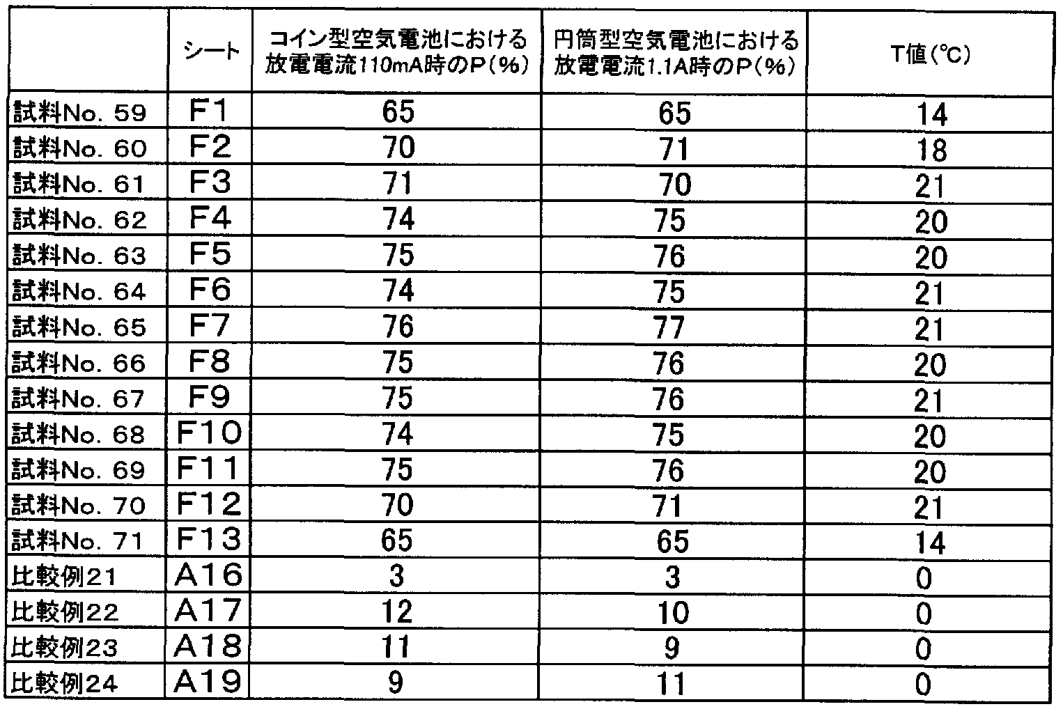
- Table 7 shows the evaluation results of the air battery and the evaluation results of the water vapor permeation suppression ability.
- the discharge efficiency P (%) is 65% or more when the coin-type air battery is discharged at a discharge current of 110 mA, and the cylindrical air battery is discharged.
- the discharge efficiency P (%) when discharged at a current of 1 A is 65% or more
- the dew point difference T (° C.) is 14 ° C. or more
- the excellent effect is obtained when the air passes through the membrane and water repellency It is because particles having the particle size can be prevented from peeling off gradually and the reduction of the water repellent effect can be prevented.
- Table 8 shows the evaluation results of the air battery and the evaluation results of the water vapor permeation suppression ability.
- the discharge efficiency P (%) is 55% or more when the coin-type air battery is discharged at a discharge current of 112 mA, and the cylindrical air battery is discharged.
- the discharge efficiency P (%) when discharged at a current of 1. 12 A is 55% or more
- the dew point difference T (° C.) is 14 ° C. or more
- sample Nos. 72, 73, 81 using a porous resin membrane as a porous base material and sample Nos. 74-80 and No. 82-88 using a mesh or non-woven fabric as a porous base material. It is at the same level as the above and is good. Therefore, the form of the porous substrate in the oxygen permeable sheet may be a mesh, a non-woven fabric or the like.
- polyethylene, polypropylene, polytet, etc. can be used as the porous substrate.
- Lafluoroethylene, vinylon, polytetrafluoroethylene (PPS), polybutylene terephthalate (PBT), nylon, etc. were preferably used.
- Table 9 shows the evaluation results of the air battery and the evaluation results of the water vapor permeation suppression ability.
- the discharge efficiency P (%) is 64% or more when the coin-type air battery is discharged at a discharge current of 115 mA, and the cylindrical air battery is discharged.
- the discharge efficiency P (%) is 65% or more and the dew point difference T (° C.) is 14 ° C. or more when discharged at a current of 1. 15 A, and Comparative Examples 29 to 32 (8 to 8). It was excellent too.
- a porous base made of metal When a porous base made of metal is used as a support for an oxygen permeable membrane, particles having water repellency can be firmly fixed to the metal part of the base, and the water vapor permeation suppressing effect is more effective. It is considered to be sustainable.
- metals in addition to the metals shown in Table 1B, all metals that can be processed into a porous state, such as iron and titanium, can be used.
- the Gurley number of the oxygen-permeable sheet of the samples No. 47 to 56 (E3 to E12) showing better characteristics is 0.5 seconds or more and 50000 seconds or less.
- transmission sheet of sample No. 49-53 (E5-E9) which showed the further more favorable characteristic is 10 second or more and 20000 second or less.
- the coverage number of sample Nos. 62 to 70 (E4 to E12) showing better characteristics is 10 seconds to 20000 seconds. It is.
- Table 10 shows the evaluation results of the air battery and the evaluation results of the water vapor permeation suppression ability.
- the sample numbers 102 to 107 also showed high values of P value and T value. Therefore, the ratio of the integrated pore volume S3 in the range of diameter 0.10 to 0.1 m to the integrated pore volume S2 in the range of diameter 0.010 to 10 / ⁇ : S3ZS2 is 0.10 or more It can be said that there is an effect.
- S3ZS2 is 1, cracking and peeling occurred in the layer of particles having water repellency because the amount of the binder was small. Cracks and peeling were not observed in samples No. 102 to 106. Therefore, S3ZS2 is preferably not less than 0.11 and not more than 0.7.
- S3ZS2 is preferably 0.2 or more and 0.7 or less is preferable.
- the S1ZS2 value and the S3ZS2 value are identical to each other, for example, sample No. 96 and sample No. 102, and sample No. 97 and sample No. 104, it is compared with sample No. 102 and sample No. 102.
- No. 104 is higher in P value and T value. Therefore, by increasing the proportion of pores with smaller diameter, the effect of suppressing the permeation of water vapor can be further enhanced.
- Table 10 shows the pore porosity of Sample Nos. 96 to 107.
- the discharge efficiency P (%) at the same time showed a value of 60% or less.
- the porosity of the oxygen permeable membrane is preferably 20% or more.
- the porosity of the oxygen permeable membrane is preferably 20 to 90%.
- the oxygen permeable membrane of the present invention can be developed in various applications because of its high ability to suppress the permeation of water vapor. For example, the following applications may be mentioned.
- Air Force A purification device that removes moisture and produces dry air and oxygen.
Abstract
Description


Claims
Priority Applications (2)
| Application Number | Priority Date | Filing Date | Title |
|---|---|---|---|
| US11/577,733 US9184449B2 (en) | 2004-10-21 | 2005-08-09 | Oxygen permeable film, oxygen permeable sheet, and cell including these |
| EP05770368A EP1785184B1 (en) | 2004-10-21 | 2005-08-09 | Oxygen-permeable film, oxygen-permeable sheet and electric cell comprising the same |
Applications Claiming Priority (4)
| Application Number | Priority Date | Filing Date | Title |
|---|---|---|---|
| JP2004307150 | 2004-10-21 | ||
| JP2004-307150 | 2004-10-21 | ||
| JP2005110458A JP5006522B2 (en) | 2004-10-21 | 2005-04-07 | Oxygen permeable membrane, oxygen permeable sheet, and battery including these |
| JP2005-110458 | 2005-04-07 |
Publications (1)
| Publication Number | Publication Date |
|---|---|
| WO2006043363A1 true WO2006043363A1 (en) | 2006-04-27 |
Family
ID=36202787
Family Applications (1)
| Application Number | Title | Priority Date | Filing Date |
|---|---|---|---|
| PCT/JP2005/014578 WO2006043363A1 (en) | 2004-10-21 | 2005-08-09 | Oxygen-permeable film, oxygen-permeable sheet and electric cell comprising the same |
Country Status (5)
| Country | Link |
|---|---|
| US (1) | US9184449B2 (en) |
| EP (1) | EP1785184B1 (en) |
| JP (1) | JP5006522B2 (en) |
| KR (1) | KR100855839B1 (en) |
| WO (1) | WO2006043363A1 (en) |
Cited By (5)
| Publication number | Priority date | Publication date | Assignee | Title |
|---|---|---|---|---|
| EP2067814A1 (en) * | 2006-08-09 | 2009-06-10 | Sumitomo Electric Fine Polymer, Inc. | Fluororesin membrane, fluororesin composite, porous fluororesin composite, processes for production of them, and separation membrane element |
| US20110003213A1 (en) * | 2009-06-30 | 2011-01-06 | Revolt Technology Ltd. | Metal-air battery with siloxane material |
| JP2011243364A (en) * | 2010-05-17 | 2011-12-01 | Nippon Telegr & Teleph Corp <Ntt> | Zinc air cell and manufacturing method of zinc air cell |
| US9421499B2 (en) | 2012-01-27 | 2016-08-23 | Sumitomo Electric Fine Polymer, Inc. | Microporous modified-polytetrafluoroethylene membrane, porous-modified-polytetrafluoroethylene-membrane composite and production process thereof, and separation membrane element |
| WO2021020571A1 (en) * | 2019-07-31 | 2021-02-04 | 東レ株式会社 | Separation film |
Families Citing this family (22)
| Publication number | Priority date | Publication date | Assignee | Title |
|---|---|---|---|---|
| JP5130627B2 (en) * | 2006-01-17 | 2013-01-30 | パナソニック株式会社 | Fuel cell power generator |
| JP2008041521A (en) * | 2006-08-09 | 2008-02-21 | Matsushita Electric Ind Co Ltd | Air battery |
| JP2008071579A (en) * | 2006-09-13 | 2008-03-27 | Matsushita Electric Ind Co Ltd | Air battery |
| JP5259146B2 (en) * | 2007-09-12 | 2013-08-07 | 株式会社東芝 | Fuel cell and fuel cell system |
| WO2011001287A2 (en) * | 2009-06-30 | 2011-01-06 | Revolt Technology Ltd. | Metal-air battery with siloxane material |
| WO2011013005A1 (en) * | 2009-07-31 | 2011-02-03 | Revolt Technology Ltd. | Metal-air battery with ion exchange material |
| JP2011096492A (en) * | 2009-10-29 | 2011-05-12 | Sony Corp | Lithium air battery |
| JP5721329B2 (en) | 2010-01-18 | 2015-05-20 | 住友化学株式会社 | Air battery, air battery stack |
| EP2583348B1 (en) | 2010-06-15 | 2016-12-14 | Fluidic, Inc. | Metal-air cell with tuned hydrophobicity |
| JP5535824B2 (en) * | 2010-08-18 | 2014-07-02 | 三菱重工業株式会社 | Aeration apparatus and seawater flue gas desulfurization apparatus equipped with the aeration apparatus |
| FR2967591B1 (en) * | 2010-11-22 | 2015-04-24 | Arkema France | PVDF MEMBRANES WITH SUPERHYDROPHOBIC SURFACE |
| US9059483B2 (en) * | 2011-07-06 | 2015-06-16 | Ngk Insulators, Ltd. | Selective oxygen-permeable substrate, positive electrode for metal-air battery, metal-air battery, and selective oxygen-permeable membrane |
| JP6020896B2 (en) * | 2011-09-15 | 2016-11-02 | 日産自動車株式会社 | Assembled battery |
| DE102011121018A1 (en) * | 2011-12-13 | 2013-06-13 | Sartorius Stedim Biotech Gmbh | Hydrophobic or oleophobic microporous polymer membrane with structurally induced Abperl effect |
| KR102019806B1 (en) * | 2012-01-16 | 2019-09-09 | 도레이 카부시키가이샤 | Composite semipermeable membrane and method for manufacturing same |
| DE102012204170A1 (en) * | 2012-03-16 | 2013-09-19 | Siemens Aktiengesellschaft | Memory structure of an electrical energy storage cell |
| JP6237233B2 (en) * | 2012-06-27 | 2017-11-29 | 東レ株式会社 | Composite semipermeable membrane and composite semipermeable membrane element |
| US9276301B2 (en) | 2012-12-07 | 2016-03-01 | Samsung Electronics Co., Ltd. | Polymeric compound, oxygen permeable membrane, and electrochemical device |
| US9343786B2 (en) | 2012-12-10 | 2016-05-17 | Samsung Electronics Co., Ltd. | Electrochemical device |
| JP2014120339A (en) * | 2012-12-17 | 2014-06-30 | Showa Denko Packaging Co Ltd | Sheath material for air secondary battery, manufacturing method of sheath material for air secondary battery and air secondary battery |
| JP6259815B2 (en) * | 2013-03-29 | 2018-01-10 | 日立造船株式会社 | Metal air battery |
| JP2020108881A (en) * | 2018-12-28 | 2020-07-16 | 日東電工株式会社 | Filter medium, filter pleat pack, and filter unit |
Citations (8)
| Publication number | Priority date | Publication date | Assignee | Title |
|---|---|---|---|---|
| JPS58225575A (en) * | 1982-06-24 | 1983-12-27 | Toshiba Corp | Air electrode and its production method |
| JPS63116725A (en) * | 1986-11-05 | 1988-05-21 | Daikin Ind Ltd | Gas separating membrane |
| JPS6483503A (en) * | 1987-09-28 | 1989-03-29 | Shirakawa Seisakusho Kk | Oxygen concentrating device |
| JPH04312771A (en) * | 1991-04-11 | 1992-11-04 | Toshiba Battery Co Ltd | Air battery |
| EP0621236A1 (en) | 1992-11-06 | 1994-10-26 | Daikin Industries, Limited | Carbon fluoride particles, process for producing the same, and use thereof |
| JPH0714565A (en) | 1993-06-24 | 1995-01-17 | Nitto Denko Corp | Battery |
| JPH07130405A (en) | 1993-10-28 | 1995-05-19 | Matsushita Electric Ind Co Ltd | Manufacture of button-shaped air-depolarized cell and porous polyolefine film |
| JP2001079369A (en) * | 1999-09-10 | 2001-03-27 | Nitto Denko Corp | Fluorocarbon resin composite material and organic electroluminescence element using the same |
Family Cites Families (21)
| Publication number | Priority date | Publication date | Assignee | Title |
|---|---|---|---|---|
| US4468360A (en) * | 1981-12-21 | 1984-08-28 | Olin Corporation | Preparing porous diaphragms for electrolytic cells having non-uniform hydrophobicity |
| JPS5975582A (en) | 1982-10-21 | 1984-04-28 | Matsushita Electric Ind Co Ltd | Air cell |
| US4650730A (en) * | 1985-05-16 | 1987-03-17 | W. R. Grace & Co. | Battery separator |
| JPH026832A (en) * | 1988-06-24 | 1990-01-11 | Daikin Ind Ltd | Porous hollow fiber of polytetrafluoroethylene and production thereof |
| JPH0245913A (en) * | 1988-08-05 | 1990-02-15 | Mitsubishi Electric Corp | Semiconductor manufacturing device |
| US5624627A (en) * | 1991-12-27 | 1997-04-29 | Mitsui Petrochemical Industries, Ltd. | Process for preparing surface-modified biaxially oriented film of high molecular weight polyethylene |
| JPH0644954A (en) | 1992-05-07 | 1994-02-18 | Nitto Denko Corp | Battery and selective permeation film used therefor |
| US5712062A (en) * | 1992-11-06 | 1998-01-27 | Daikin Industries, Ltd. | Carbon fluoride particles, preparation process and uses of the same |
| JP2780903B2 (en) * | 1993-02-26 | 1998-07-30 | 日本電信電話株式会社 | A material excellent in water repellency, corrosion resistance, snow resistance, weather resistance and lubricity and a method for producing the same |
| JP3266969B2 (en) * | 1993-03-11 | 2002-03-18 | ダイキン工業株式会社 | Manufacturing method of fluororesin sintered body |
| US5563004A (en) * | 1995-03-21 | 1996-10-08 | Aer Energy Resources, Inc. | Rechargeable metal-air electrochemical cell with hydrogen recombination and end-of-charge indicator |
| EP1139470A1 (en) | 1998-11-16 | 2001-10-04 | Toray Industries, Inc. | Porous conductive sheet and method for producing the same |
| US6632557B1 (en) * | 1999-10-26 | 2003-10-14 | The Gillette Company | Cathodes for metal air electrochemical cells |
| KR200180458Y1 (en) * | 1999-12-09 | 2000-05-01 | 신현배 | Headrest of car including kneader |
| JP2002343369A (en) * | 2001-05-15 | 2002-11-29 | Aisin Seiki Co Ltd | Manufacturing method of electrode for fuel cell, and fuel cell |
| JP3946549B2 (en) * | 2002-03-08 | 2007-07-18 | 日本バイリーン株式会社 | Water-repellent particle-carrying fiber, water-repellent particle-carrying fiber sheet, method for producing the same, and garment using the same |
| US6921606B2 (en) * | 2002-04-16 | 2005-07-26 | Gore Enterprise Holdings, Inc. | Composite films for electrochemical devices |
| AU2003231512A1 (en) * | 2002-04-30 | 2003-11-17 | Daikin Industries, Ltd. | Surface treating composition excellent in water repellency and water sliding property |
| CN1303708C (en) | 2002-07-31 | 2007-03-07 | 曹喜峰 | Air electride |
| US20040241537A1 (en) * | 2003-03-28 | 2004-12-02 | Tetsuo Okuyama | Air battery |
| JP4031740B2 (en) * | 2003-07-15 | 2008-01-09 | 日東電工株式会社 | Fuel cell separator and fuel cell using the same |
-
2005
- 2005-04-07 JP JP2005110458A patent/JP5006522B2/en not_active Expired - Fee Related
- 2005-08-09 US US11/577,733 patent/US9184449B2/en not_active Expired - Fee Related
- 2005-08-09 EP EP05770368A patent/EP1785184B1/en not_active Expired - Fee Related
- 2005-08-09 WO PCT/JP2005/014578 patent/WO2006043363A1/en active Application Filing
- 2005-08-09 KR KR1020077006125A patent/KR100855839B1/en not_active IP Right Cessation
Patent Citations (8)
| Publication number | Priority date | Publication date | Assignee | Title |
|---|---|---|---|---|
| JPS58225575A (en) * | 1982-06-24 | 1983-12-27 | Toshiba Corp | Air electrode and its production method |
| JPS63116725A (en) * | 1986-11-05 | 1988-05-21 | Daikin Ind Ltd | Gas separating membrane |
| JPS6483503A (en) * | 1987-09-28 | 1989-03-29 | Shirakawa Seisakusho Kk | Oxygen concentrating device |
| JPH04312771A (en) * | 1991-04-11 | 1992-11-04 | Toshiba Battery Co Ltd | Air battery |
| EP0621236A1 (en) | 1992-11-06 | 1994-10-26 | Daikin Industries, Limited | Carbon fluoride particles, process for producing the same, and use thereof |
| JPH0714565A (en) | 1993-06-24 | 1995-01-17 | Nitto Denko Corp | Battery |
| JPH07130405A (en) | 1993-10-28 | 1995-05-19 | Matsushita Electric Ind Co Ltd | Manufacture of button-shaped air-depolarized cell and porous polyolefine film |
| JP2001079369A (en) * | 1999-09-10 | 2001-03-27 | Nitto Denko Corp | Fluorocarbon resin composite material and organic electroluminescence element using the same |
Non-Patent Citations (2)
| Title |
|---|
| "Super water-repellency and super water-repellent technology", TECHNICAL INFORMATION INSTITUTE CO. LTD., pages: 155 - 163 |
| See also references of EP1785184A4 |
Cited By (11)
| Publication number | Priority date | Publication date | Assignee | Title |
|---|---|---|---|---|
| EP2067814A1 (en) * | 2006-08-09 | 2009-06-10 | Sumitomo Electric Fine Polymer, Inc. | Fluororesin membrane, fluororesin composite, porous fluororesin composite, processes for production of them, and separation membrane element |
| CN101501113A (en) * | 2006-08-09 | 2009-08-05 | 住友电工超效能高分子股份有限公司 | Fluororesin membrane, fluororesin composite, porous fluororesin composite, processes for production of them, and separation membrane element |
| US20100203310A1 (en) * | 2006-08-09 | 2010-08-12 | Sumitomo Electric Fine Polymer, Inc. | Fluororesin thin film, fluororesin composite, porous fluororesin composite, manufacturing methods thereof, and seperation membrane element |
| EP2067814A4 (en) * | 2006-08-09 | 2012-09-12 | Sumitomo Elec Fine Polymer Inc | Fluororesin membrane, fluororesin composite, porous fluororesin composite, processes for production of them, and separation membrane element |
| US9463420B2 (en) | 2006-08-09 | 2016-10-11 | Sumitomo Electric Fine Polymer, Inc. | Manufacturing methods for a porous fluororesin composite |
| US20110003213A1 (en) * | 2009-06-30 | 2011-01-06 | Revolt Technology Ltd. | Metal-air battery with siloxane material |
| JP2011243364A (en) * | 2010-05-17 | 2011-12-01 | Nippon Telegr & Teleph Corp <Ntt> | Zinc air cell and manufacturing method of zinc air cell |
| US9421499B2 (en) | 2012-01-27 | 2016-08-23 | Sumitomo Electric Fine Polymer, Inc. | Microporous modified-polytetrafluoroethylene membrane, porous-modified-polytetrafluoroethylene-membrane composite and production process thereof, and separation membrane element |
| WO2021020571A1 (en) * | 2019-07-31 | 2021-02-04 | 東レ株式会社 | Separation film |
| JPWO2021020571A1 (en) * | 2019-07-31 | 2021-09-13 | 東レ株式会社 | Separation membrane |
| US11617991B2 (en) | 2019-07-31 | 2023-04-04 | Toray Industries, Inc. | Separation film |
Also Published As
| Publication number | Publication date |
|---|---|
| US9184449B2 (en) | 2015-11-10 |
| JP5006522B2 (en) | 2012-08-22 |
| EP1785184A4 (en) | 2010-02-24 |
| JP2006142275A (en) | 2006-06-08 |
| EP1785184A1 (en) | 2007-05-16 |
| KR20070047828A (en) | 2007-05-07 |
| KR100855839B1 (en) | 2008-09-01 |
| US20090202876A1 (en) | 2009-08-13 |
| EP1785184B1 (en) | 2013-01-09 |
Similar Documents
| Publication | Publication Date | Title |
|---|---|---|
| WO2006043363A1 (en) | Oxygen-permeable film, oxygen-permeable sheet and electric cell comprising the same | |
| CN107256939B (en) | Laminated porous film and nonaqueous electrolyte secondary battery | |
| JP6153992B2 (en) | Nonaqueous electrolyte secondary battery separator | |
| CA1194925A (en) | Oxygen gas permselective membrane | |
| CN100562353C (en) | Oxygen-permeable film, oxygen see through sheet and comprise their battery | |
| WO2017033993A1 (en) | Cell separator and method for manufacturing same | |
| KR101965915B1 (en) | Separator and method for producing same | |
| FR2488051A1 (en) | CIPO - Patent | |
| WO2005119830A1 (en) | Exterior cladding thin-film for alkali battery and thin air battery utilizing the same | |
| JP4777615B2 (en) | Electrochemical equipment alignment film | |
| KR102345166B1 (en) | Porous laminate film and non-aqueous electrolyte secondary battery | |
| WO2018056307A1 (en) | Air cell and patch | |
| JP6250551B2 (en) | Method for producing functional porous body | |
| WO2018105301A1 (en) | Gas diffusion electrode and production method therefor | |
| JP2007141745A (en) | Air battery | |
| JP2018037310A (en) | Separator for nonaqueous electrolyte secondary battery | |
| JP2008071579A (en) | Air battery | |
| JP3886845B2 (en) | Porous membrane for temperature / humidity exchanger and method for producing the same | |
| JP2023129131A (en) | Separator for non-aqueous electrolyte secondary battery, member for non-aqueous electrolyte secondary battery, and non-aqueous electrolyte secondary battery | |
| JP2023129128A (en) | Separator for non-aqueous electrolyte secondary battery, member for non-aqueous electrolyte secondary battery, and non-aqueous electrolyte secondary battery | |
| JP2023129130A (en) | Separator for non-aqueous electrolyte secondary battery, member for non-aqueous electrolyte secondary battery, and non-aqueous electrolyte secondary battery | |
| JPH03297055A (en) | Battery | |
| JPS58225575A (en) | Air electrode and its production method | |
| JPS5946102A (en) | Composite membrane selectively permeable for gaseous oxygen | |
| JPS5994382A (en) | Air battery |
Legal Events
| Date | Code | Title | Description |
|---|---|---|---|
| AK | Designated states |
Kind code of ref document: A1 Designated state(s): AE AG AL AM AT AU AZ BA BB BG BR BW BY BZ CA CH CN CO CR CU CZ DE DK DM DZ EC EE EG ES FI GB GD GE GH GM HR HU ID IL IN IS KE KG KM KP KR KZ LC LK LR LS LT LU LV MA MD MG MK MN MW MX MZ NA NG NI NO NZ OM PG PH PL PT RO RU SC SD SE SG SK SL SM SY TJ TM TN TR TT TZ UA UG US UZ VC VN YU ZA ZM ZW |
|
| AL | Designated countries for regional patents |
Kind code of ref document: A1 Designated state(s): BW GH GM KE LS MW MZ NA SD SL SZ TZ UG ZM ZW AM AZ BY KG KZ MD RU TJ TM AT BE BG CH CY CZ DE DK EE ES FI FR GB GR HU IE IS IT LT LU LV MC NL PL PT RO SE SI SK TR BF BJ CF CG CI CM GA GN GQ GW ML MR NE SN TD TG |
|
| 121 | Ep: the epo has been informed by wipo that ep was designated in this application | ||
| WWE | Wipo information: entry into national phase |
Ref document number: 2005770368 Country of ref document: EP |
|
| WWE | Wipo information: entry into national phase |
Ref document number: 200580026856.5 Country of ref document: CN |
|
| WWE | Wipo information: entry into national phase |
Ref document number: 1020077006125 Country of ref document: KR |
|
| WWE | Wipo information: entry into national phase |
Ref document number: 11577733 Country of ref document: US |
|
| NENP | Non-entry into the national phase |
Ref country code: DE |
|
| WWP | Wipo information: published in national office |
Ref document number: 2005770368 Country of ref document: EP |