US9998024B2 - Power conversion apparatus - Google Patents
Power conversion apparatus Download PDFInfo
- Publication number
- US9998024B2 US9998024B2 US15/027,000 US201415027000A US9998024B2 US 9998024 B2 US9998024 B2 US 9998024B2 US 201415027000 A US201415027000 A US 201415027000A US 9998024 B2 US9998024 B2 US 9998024B2
- Authority
- US
- United States
- Prior art keywords
- power
- power conversion
- conversion apparatus
- functional modules
- heat
- Prior art date
- Legal status (The legal status is an assumption and is not a legal conclusion. Google has not performed a legal analysis and makes no representation as to the accuracy of the status listed.)
- Active
Links
Images


Classifications
-
- H—ELECTRICITY
- H02—GENERATION; CONVERSION OR DISTRIBUTION OF ELECTRIC POWER
- H02M—APPARATUS FOR CONVERSION BETWEEN AC AND AC, BETWEEN AC AND DC, OR BETWEEN DC AND DC, AND FOR USE WITH MAINS OR SIMILAR POWER SUPPLY SYSTEMS; CONVERSION OF DC OR AC INPUT POWER INTO SURGE OUTPUT POWER; CONTROL OR REGULATION THEREOF
- H02M7/00—Conversion of ac power input into dc power output; Conversion of dc power input into ac power output
- H02M7/02—Conversion of ac power input into dc power output without possibility of reversal
- H02M7/04—Conversion of ac power input into dc power output without possibility of reversal by static converters
-
- B—PERFORMING OPERATIONS; TRANSPORTING
- B60—VEHICLES IN GENERAL
- B60L—PROPULSION OF ELECTRICALLY-PROPELLED VEHICLES; SUPPLYING ELECTRIC POWER FOR AUXILIARY EQUIPMENT OF ELECTRICALLY-PROPELLED VEHICLES; ELECTRODYNAMIC BRAKE SYSTEMS FOR VEHICLES IN GENERAL; MAGNETIC SUSPENSION OR LEVITATION FOR VEHICLES; MONITORING OPERATING VARIABLES OF ELECTRICALLY-PROPELLED VEHICLES; ELECTRIC SAFETY DEVICES FOR ELECTRICALLY-PROPELLED VEHICLES
- B60L9/00—Electric propulsion with power supply external to the vehicle
- B60L9/16—Electric propulsion with power supply external to the vehicle using ac induction motors
- B60L9/30—Electric propulsion with power supply external to the vehicle using ac induction motors fed from different kinds of power-supply lines
-
- B—PERFORMING OPERATIONS; TRANSPORTING
- B61—RAILWAYS
- B61D—BODY DETAILS OR KINDS OF RAILWAY VEHICLES
- B61D27/00—Heating, cooling, ventilating, or air-conditioning
-
- H—ELECTRICITY
- H02—GENERATION; CONVERSION OR DISTRIBUTION OF ELECTRIC POWER
- H02M—APPARATUS FOR CONVERSION BETWEEN AC AND AC, BETWEEN AC AND DC, OR BETWEEN DC AND DC, AND FOR USE WITH MAINS OR SIMILAR POWER SUPPLY SYSTEMS; CONVERSION OF DC OR AC INPUT POWER INTO SURGE OUTPUT POWER; CONTROL OR REGULATION THEREOF
- H02M3/00—Conversion of dc power input into dc power output
- H02M3/02—Conversion of dc power input into dc power output without intermediate conversion into ac
- H02M3/04—Conversion of dc power input into dc power output without intermediate conversion into ac by static converters
-
- H—ELECTRICITY
- H02—GENERATION; CONVERSION OR DISTRIBUTION OF ELECTRIC POWER
- H02M—APPARATUS FOR CONVERSION BETWEEN AC AND AC, BETWEEN AC AND DC, OR BETWEEN DC AND DC, AND FOR USE WITH MAINS OR SIMILAR POWER SUPPLY SYSTEMS; CONVERSION OF DC OR AC INPUT POWER INTO SURGE OUTPUT POWER; CONTROL OR REGULATION THEREOF
- H02M7/00—Conversion of ac power input into dc power output; Conversion of dc power input into ac power output
- H02M7/003—Constructional details, e.g. physical layout, assembly, wiring or busbar connections
-
- H—ELECTRICITY
- H02—GENERATION; CONVERSION OR DISTRIBUTION OF ELECTRIC POWER
- H02M—APPARATUS FOR CONVERSION BETWEEN AC AND AC, BETWEEN AC AND DC, OR BETWEEN DC AND DC, AND FOR USE WITH MAINS OR SIMILAR POWER SUPPLY SYSTEMS; CONVERSION OF DC OR AC INPUT POWER INTO SURGE OUTPUT POWER; CONTROL OR REGULATION THEREOF
- H02M7/00—Conversion of ac power input into dc power output; Conversion of dc power input into ac power output
- H02M7/42—Conversion of dc power input into ac power output without possibility of reversal
- H02M7/44—Conversion of dc power input into ac power output without possibility of reversal by static converters
-
- H—ELECTRICITY
- H05—ELECTRIC TECHNIQUES NOT OTHERWISE PROVIDED FOR
- H05K—PRINTED CIRCUITS; CASINGS OR CONSTRUCTIONAL DETAILS OF ELECTRIC APPARATUS; MANUFACTURE OF ASSEMBLAGES OF ELECTRICAL COMPONENTS
- H05K7/00—Constructional details common to different types of electric apparatus
- H05K7/20—Modifications to facilitate cooling, ventilating, or heating
- H05K7/2089—Modifications to facilitate cooling, ventilating, or heating for power electronics, e.g. for inverters for controlling motor
- H05K7/20909—Forced ventilation, e.g. on heat dissipaters coupled to components
-
- B—PERFORMING OPERATIONS; TRANSPORTING
- B60—VEHICLES IN GENERAL
- B60L—PROPULSION OF ELECTRICALLY-PROPELLED VEHICLES; SUPPLYING ELECTRIC POWER FOR AUXILIARY EQUIPMENT OF ELECTRICALLY-PROPELLED VEHICLES; ELECTRODYNAMIC BRAKE SYSTEMS FOR VEHICLES IN GENERAL; MAGNETIC SUSPENSION OR LEVITATION FOR VEHICLES; MONITORING OPERATING VARIABLES OF ELECTRICALLY-PROPELLED VEHICLES; ELECTRIC SAFETY DEVICES FOR ELECTRICALLY-PROPELLED VEHICLES
- B60L2200/00—Type of vehicles
- B60L2200/26—Rail vehicles
Definitions
- the present invention relates to a power conversion apparatus that performs power conversion by using semiconductor components.
- An existing power conversion apparatus provided in a railway vehicle includes a heat generating section having various semiconductor units, and a heat radiating section cooling the heat generating section.
- the heat generating section and the heat radiating section are configured to be able to be separated, and thus the power conversion apparatus in which workability of assembly and maintainability are improved has been proposed (see Patent Literature 1, for example).
- Patent Literature 1 Japanese Unexamined Patent Application Publication No. 2003-235112 (paragraph [0012])
- a power conversion apparatus used in a railway vehicle is required to be design to adapt to a plurality of different power sources in different regions that are derived from a difference between a direct current and an alternating current, or a difference between a single-phase alternating current and a three-phase alternating current, for example.
- the power conversion apparatus disclosed in Patent Literature 1 has a structure in which semiconductor components are mounted on one substrate so that a necessary power conversion characteristic is satisfied. Hence, the entire power conversion apparatus has to be reassembled.
- the present invention has been made to solve the above-described problem, and an object thereof is to provide a power conversion apparatus that enables shared use of semiconductor components to be made and a reduction in reliability to be prevented.
- a power conversion apparatus is a power conversion apparatus providing a supply to an air-conditioning apparatus provided in a railway vehicle, and includes a power converter including a functional module in which a power conversion unit constituted by a semiconductor component and configured to convert power is mounted.
- the power converter includes any one or more of a functional module in which a rectifier unit rectifying an externally supplied alternating-current voltage and an inverter unit converting a direct-current voltage into alternating-current power are combined, a functional module in which a converter unit converting an alternating-current voltage into a direct-current voltage and an inverter unit converting a direct-current voltage converted by the converter unit into alternating-current power are combined, and a functional module in which an inverter unit converting a direct-current voltage into alternating-current power is provided.
- the functional module has a cooler cooling the semiconductor component.
- the power conversion apparatus of the present invention when the power converter is constituted by a combination of functional modules so that necessary capacity is provided, shared use of semiconductor components is promoted, and thus a reduction in reliability due to an increase in the number of semiconductor components can be prevented.
- FIG. 1 illustrates an example of an arrangement configuration of functional modules 7 in Embodiment 1 of the present invention.
- FIG. 2 illustrates an example of a functional configuration of a power conversion apparatus 2 in Embodiment 1 of the present invention.
- FIG. 3A illustrates an example of a power converter constituted by three functional modules 7 _ 1 to 7 _ 3 .
- FIG. 3B illustrates an example of the power converter constituted by the three functional modules 7 _ 1 to 7 _ 3 .
- FIG. 3C includes graphs illustrating a situation in which power is converted in the power converter 5 illustrated in FIGS. 3A and 3B .
- FIG. 4A illustrates an example of the power converter constituted by two functional modules 7 _ 1 and 7 _ 2 .
- FIG. 4B illustrates an example of the power converter constituted by the two functional modules 7 _ 1 and 7 _ 2 .
- FIG. 4C includes graphs illustrating a situation in which power is converted in the power converter 5 illustrated in FIGS. 4A and 4B .
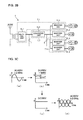
- FIG. 5A illustrates an example of the power converter constituted by one functional module 7 _ 1 .
- FIG. 5B illustrates an example of the power converter constituted by the one functional module 7 _ 1 .
- FIG. 5C includes graphs illustrating a situation in which power is converted in the power converter 5 illustrated in FIGS. 5A and 5B .
- FIG. 6 illustrates an example of an arrangement configuration of various power conversion units in a case where a functionally-modularized form is not established.
- FIG. 7 illustrates an example of an arrangement configuration of various power conversion units in the case where a functionally-modularized form is established in Embodiment 1 of the present invention.
- FIG. 8 illustrates an example of the configuration of distribution of heat generation in the case where a functionally-modularized form is not established.
- FIG. 9 illustrates an example of the configuration of distribution of heat generation in the case where a functionally-modularized form is established in Embodiment 1 of the present invention.
- FIG. 10 illustrates an example of the configuration of temperature distribution in the case where a functionally-modularized form is not established.
- FIG. 11 illustrates an example of the configuration of temperature distribution in the case where a functionally-modularized form is established in Embodiment 1 of the present invention.
- FIG. 12 illustrates an example of a location relationship between functional modules 7 and the cooler 6 in Embodiment 2 of the present invention.
- FIG. 13 illustrates an example of a railway vehicle 51 in which the power conversion apparatus 2 is installed in Embodiment 3 of the present invention.
- Embodiments of the present invention will be described in detail below with reference to the drawings. Note that, in Embodiments 1 to 4, elements not specifically described are common to Embodiments 1 to 4, and the same functions and configurations will be described using the same reference numerals.
- FIG. 1 illustrates an example of an arrangement configuration of functional modules in a power conversion apparatus in Embodiment 1 of the present invention.
- FIG. 2 illustrates an example of a functional configuration of the power conversion apparatus in Embodiment 1 of the present invention.
- a power conversion apparatus 2 includes a cooling fan unit 21 , a capacitor unit 4 , and a power converter 5 .
- the cooling fan unit 21 includes a plurality of cooling fans 23 .
- the power converter 5 is accommodated in an accommodating section 50 , and a closed chamber 8 and an open chamber 9 are accommodated in the accommodating section 50 .
- the closed chamber 8 is an enclosed space that is closed off from the outside.
- the open chamber 9 is a space with an opening that communicates with outside air.
- a cooler 6 is disposed in the open chamber 9 .
- the power converter 5 is disposed in the closed chamber 8 , protection against dust and protection against water are achieved, and thus, in particular, iron dust or other dust is prevented from entering into a functional module because of a railway vehicle and resulting in deterioration of the functional module.
- the power converter 5 includes a functional module 7 _ 1 , a functional module 7 _ 2 , and a functional module 7 _ 3 .
- each functional module one or more power conversion units configured to convert power are formed, the one or more power conversion units are each constituted by a semiconductor component.
- the functional module 7 _ 1 to the functional module 7 _ 3 are each provided on the capacitor unit 4 in such a manner as to be demountable from the capacitor unit 4 .
- the functional module 7 _ 3 can be replaced with a fourth functional module 7 _ 4 having another power conversion characteristic when necessary.
- the number and shapes of functional modules are not limited to particular number and shapes, and it is only necessary that the number be one or more.
- the functional module 7 _ 1 includes a rectifier unit 15 _ 1 that rectifies an externally supplied alternating-current voltage, and an inverter unit 11 _ 1 that converts a direct-current voltage converted by the rectifier unit 15 _ 1 into alternating-current power.
- the rectifier unit 15 _ 1 converts single-phase or three-phase alternating-current power into a direct-current voltage.
- the inverter unit 11 _ 1 converts the direct-current voltage converted by the rectifier unit 15 _ 1 into predetermined three-phase alternating-current power.
- the functional module 7 _ 2 includes a converter unit 13 _ 2 that converts an externally supplied varying input voltage into a stable direct-current voltage, and an inverter unit 11 _ 2 that converts the direct-current voltage converted by the converter unit into alternating-current power.
- the converter unit 13 _ 2 converts a varying input voltage into a stable direct-current voltage.
- the inverter unit 11 _ 2 converts the direct-current voltage converted by the converter unit 13 _ 2 into predetermined three-phase alternating-current power.
- the functional module 7 _ 3 includes a plurality of inverter units 11 _ 3 and 11 _ 4 that each convert a direct-current voltage into alternating-current power.
- the inverter unit 11 _ 3 and the inverter unit 11 _ 4 each convert a direct-current voltage into predetermined three-phase alternating-current power.
- a functional module 7 _ 3 in which two inverter units 11 _ 3 and 11 _ 4 are used is illustrated, a functional module can be constituted by arranging three inverter units as long as the functional module is nearly uniform with the other functional modules in the amount of heat generated and the size.
- a functional module can be constituted by one inverter unit if the capacity of the inverter unit is large, the functional module is constituted by typically a plurality of, preferably two inverter units.
- the converter unit 13 _ 2 and the inverter units 11 _ 1 to 11 _ 3 are constituted by an IGBT (Insulated Gate Bipolar Transistor) with which a diode is connected in anti-parallel, a MOSFET (Metal Oxide Semiconductor Field Effect Transistor) in which a diode is disposed between a source and a drain, or a mechanical switch, for example.
- IGBT Insulated Gate Bipolar Transistor
- MOSFET Metal Oxide Semiconductor Field Effect Transistor
- the converter unit 13 _ 2 and the inverter units 11 _ 1 to 11 _ 3 may be constituted by, for example, SiC.
- a plurality of functional modules 7 _ 1 to 7 _ 3 can each be formed and separated as an independent module, and are demountable.
- the functional modules 7 _ 1 to 7 _ 3 are each fastened to the capacitor unit 4 by using, for example, screws, and demounting can be performed for each of the functional modules 7 _ 1 to 7 _ 3 for maintenance or replacement.
- maintenance, inspections, and replacement for example, can be carried out for each of the functional modules 7 _ 1 to 7 _ 3 even in the case of a breakdown of a device, and thus shared use of structural components can be made, and also maintenance costs can be reduced.
- each of the functional modules 7 _ 1 to 7 _ 3 the sizes of power conversion units are designed. For example, in each of the functional modules 7 _ 1 to 7 _ 3 , by providing a large power conversion unit and a small power conversion unit, the amounts of heat generated from the respective power conversion units are distributed for each of the functional modules 7 _ 1 to 7 _ 3 , thus resulting in a situation in which the amount of heat generated per each of the functional modules 7 _ 1 to 7 _ 3 is spread.
- various power conversion units constituting the inverter units 11 _ 1 to 11 _ 4 are arranged on the basis of the arrangement and number thereof in which the amounts of heat generated are distributed.
- distribution of heat generation with less unevenness is achieved, and thus temperature distribution is balanced.
- the levels of cooling air necessary for the respective functional modules 7 _ 1 to 7 _ 3 may be equal.
- the cooling fans 23 of the same specifications can cool the respective functional modules 7 _ 1 to 7 _ 3 .
- the power conversion units are arranged so that the length of a conductor line providing a connection between power conversion units is reduced and the number of bends is reduced.
- a wiring structure W that reduces wiring losses is achieved.
- the inverter units 11 _ 1 to the inverter unit 11 _ 4 are arranged so that the wiring structure is straight wiring.
- conductors connecting semiconductor components are provided at locations facing each other.
- the power conversion apparatus 2 enables assembly work of the power conversion units to be simplified and also a reduction in wiring inductance.
- the power converter 5 of the power conversion apparatus 2 As described above, in the power converter 5 of the power conversion apparatus 2 , structural components are separated into the plurality of functional modules 7 _ 1 to 7 _ 3 , and thus the power converter 5 is constituted by a combination of the plurality of functional modules 7 _ 1 to 7 _ 3 .
- the power converter 5 enables the structural components to be separated into the plurality of functional modules 7 _ 1 to 7 _ 3 even in the case of a breakdown of a device, and thus maintenance, inspections, and replacement, for example, can be carried out for each of the functional modules 7 _ 1 to 7 _ 3 .
- the power conversion apparatus 2 enables shared use of the structural components and also a reduction in maintenance costs.
- the sharable functional modules 7 _ 1 to 7 _ 3 can be shared even in the case of any power source. As a result, a reduction in reliability due to an increase in the number of semiconductor components can be prevented.
- electricity is supplied to a railway vehicle from an overhead line via a pantograph.
- Examples of power supplied to the power conversion apparatus 2 from the overhead line include various types, such as DC 600 V, DC 750 V, DC 1500 V, AC 20 kV, and AC 25 kV, from region to region.
- the power converter 5 has to have a power conversion characteristic that matches the type of power supplied from the overhead line.
- a different type of power converter 5 has to be produced for each of requirements varying between, for example, regions where a railway vehicle runs, resulting in an increase in costs and also taking time and effort in maintenance.
- the power converter 5 is constituted by at least one of the functional modules 7 _ 1 to 7 _ 3 selected from among three functional modules 7 _ 1 to 7 _ 3 in response to input power.
- FIGS. 3A and 3B each illustrate an example of the power converter constituted by three functional modules 7 _ 1 to 7 _ 3
- FIGS. 4A and 4B each illustrate an example of the power converter constituted by two functional modules 7 _ 1 and 7 _ 2
- FIGS. 5A and 5B each illustrate an example of the power converter constituted by one functional module 7 _ 1 .
- the power converter 5 illustrated in FIGS. 3A and 3B is constituted by a combination of three functional modules 7 _ 1 to 7 _ 3 , converts an alternating-current voltage of 25 kV, and supplies power to compressors CPs, an outdoor air-sending device CF, an indoor air-sending device EF, and the capacitor unit 4 .
- FIG. 3C includes graphs illustrating a situation in which power is converted in the power converter 5 illustrated in FIGS. 3A and 3B .
- the rectifier unit 15 _ 1 of the functional module 7 _ 1 rectifies externally input single-phase alternating-current power (see FIG. 3C (a)) into direct-current power (see FIG. 3C (b)), and outputs the direct-current power to the capacitor unit 4 that stores direct-current power, and the converter unit 13 _ 2 of the functional module 7 _ 2 .
- the converter unit 13 _ 2 of the functional module 7 _ 2 converts the voltage rectified in the rectifier unit 15 _ 1 into a stable direct-current voltage (see FIG. 3C (c)).
- the direct-current voltage stabilized in the converter unit 13 _ 2 is converted into an alternating-current voltage in each of the inverter units 11 _ 1 to 11 _ 3 of the functional modules 7 _ 1 to 7 _ 3 (see FIG. 3C (d)), and loads, such as the compressors CPs, the outdoor air-sending device CF, and the indoor air-sending device EF, are actuated.
- the power converter 5 illustrated in FIGS. 4A and 4B is constituted by a combination of two functional modules 7 _ 1 and 7 _ 2 , converts a direct-current voltage of 600 V, and provides a supply to a compressor CP, the outdoor air-sending device CF, the indoor air-sending device EF, and the capacitor unit 4 .
- FIG. 4C includes graphs illustrating a situation in which power is converted in the power converter 5 illustrated in FIGS. 4A and 4B .
- the rectifier unit 15 _ 1 of the functional module 7 _ 1 rectifies externally input direct-current power (see FIG. 4C (a)), and outputs the rectified power to the capacitor unit 4 that stores direct-current power, and the converter unit 13 _ 2 of the functional module 7 _ 2 .
- the converter unit 13 _ 2 of the functional module 7 _ 2 converts the voltage rectified in the rectifier unit 15 _ 1 into a stable direct-current voltage (see FIG. 40( b ) ).
- the direct-current voltage stabilized in the converter unit 13 _ 2 is converted into an alternating-current voltage in each of the inverter units 11 _ 1 and 11 _ 2 of the respective functional module 7 _ 1 and 7 _ 2 (see FIG. 4C (c)), and loads, such as the compressor CP, the outdoor air-sending device CF, and the indoor air-sending device EF, are actuated.
- the power converter 5 illustrated in FIGS. 5A and 5B is constituted by one functional module 7 _ 1 , and an alternating-current voltage converted from a direct-current voltage of 1500 V via a static inverter SIV is input to the power converter 5 . Then, the power converter 5 converts the input voltage, and supplies power to compressors CPs, the outdoor air-sending device CF, the indoor air-sending device EF, and the capacitor unit 4 . Furthermore, FIG. 5C includes graphs illustrating a situation in which power is converted in the power converter 5 illustrated in FIGS. 5A and 5B .
- the rectifier unit 15 _ 1 of the functional module 7 _ 1 rectifies alternating-current power input from the static inverter SIV (see FIG. 50( a ) ), and outputs the rectified power to the capacitor unit 4 that stores direct-current power, and the inverter unit 11 _ 1 of the functional module 7 _ 1 (see FIG. 5C (b)).
- the direct-current voltage rectified in the rectifier unit 15 _ 1 is converted into an alternating-current voltage in the inverter unit 11 _ 1 of the functional module 7 _ 1 (see FIG. 5C (c)), and loads, such as the compressors CPs, the outdoor air-sending device CF, and the indoor air-sending device EF, are actuated.
- the power converter 5 can be constituted by varying combinations of the functional modules 7 _ 1 to 7 _ 3 so that each combination matches the type of power supplied from the overhead line.
- the sharable functional modules 7 _ 1 to 7 _ 3 are shared even in the case of any power source, and thus a reduction in reliability due to an increase in the number of semiconductor components can be prevented.
- the functional modules 7 _ 1 to 7 _ 3 have the cooler 6 configured to transfer heat generated from semiconductor components.
- the cooler 6 is constituted by, for example, a heat sink, and includes, as illustrated in FIG. 12 , a heat receiving section (base plate) 43 that is in contact with semiconductor components of the functional modules 7 _ 1 to 7 _ 3 , and a heat radiating section (heat radiating fins) 41 that is formed integrally with the heat receiving section and transfers heat conducted from the heat receiving section.
- the cooler 6 may be provided for each of the functional modules 7 _ 1 to 7 _ 3 , or one cooler 6 may be provided for a combination of the functional modules 7 _ 1 to 7 _ 3 as a whole.
- the power conversion apparatus 2 there are achieved the number and arrangement configuration of power conversion units in which the amounts of heat generated in the respective functional modules 7 _ 1 to 7 _ 3 are spread so that they are balanced, thus enabling simplification of the configuration of the cooler 6 .
- FIG. 6 illustrates an example of a power conversion apparatus in a case where a functionally-modularized form is not established.
- FIG. 7 illustrates an example of the power conversion apparatus in Embodiment 1 of the present invention.
- a power conversion apparatus 1 illustrated in FIG. 6 includes semiconductor components configured to convert power necessary for all railway vehicles.
- the power conversion apparatus 2 illustrated in FIG. 7 is constituted by, for example, a combination of two functional modules 7 _ 1 and 7 _ 2 , and thereby converts power necessary for all railway vehicles.
- the inverter unit 11 _ 1 , the inverter unit 11 _ 2 , the converter unit 13 _ 2 , and the rectifier unit 15 _ 1 are mounted on the heat receiving section 43 .
- the inverter unit 11 _ 1 , the inverter unit 11 _ 2 , the converter unit 13 _ 2 , and the rectifier unit 15 _ 1 are arranged in such a manner as to leave a certain distance between each other in view of radiation characteristics of heat from each semiconductor component.
- the power conversion apparatus 2 in the case where a functionally-modularized form is established is constituted by a combination of the functional module 7 _ 1 and the functional module 7 _ 2 .
- the inverter unit 11 _ 3 other than the inverter unit 11 _ 1 having the highest capacity among a plurality of inverter units 11 _ 1 to 11 _ 3 is selected and constitutes the functional module 7 _ 1 . Furthermore, since the amount of heat generated in the rectifier unit 15 _ 1 is not very large, the inverter unit 11 _ 1 having the highest capacity among the plurality of inverter units 11 _ 1 to 11 _ 3 is selected and can constitute the functional module 7 _ 2 . Although the case where there are two inverter units is illustrated in FIG.
- FIG. 8 illustrates an example of the configuration of distribution of heat generation in the case where a functionally-modularized form is not established in Embodiment 1 of the present invention.
- FIG. 9 illustrates an example of the configuration of distribution of heat generation in the case where a functionally-modularized form is established in Embodiment 1 of the present invention.
- a region in which the amount of heat generated is high is smaller in size than a region in which the amount of heat generated is zero.
- a region in which the amount of heat generated is high is larger in size than a region in which the amount of heat generated is zero.
- the amount of heat generated on an inverter unit 11 _ 1 side is 5 to 10 W/cm 2
- the range of the amount of heat generated on an inverter unit 11 _ 2 side is 5 to 10 W/cm 2
- the ranges of the amount of heat generated on a converter unit 13 _ 2 side are 15 to 20 W/cm 2 , 10 to 15 W/cm 2 , and 5 to 10 W/cm 2 in the order from the center to the periphery
- the ranges of the amount of heat generated on a rectifier unit 15 _ 1 side are 15 to 20 W/cm 2 on a left center side and a right center side, 10 to 15 W/cm 2 on the periphery of the regions of 15 to 20 W/cm 2 , and 5 to 10 W/cm 2 on the periphery of the region of 10 to 15 W/cm 2 .
- the range of the amount of heat generated on an inverter unit 11 _ 2 side is 5 to 10 W/cm 2
- the ranges of the amount of heat generated on a converter unit 13 _ 2 side are 15 to 20 W/cm 2 , 10 to 15 W/cm 2 , and 5 to 10 W/cm 2 in the order from the center to the periphery.
- the ranges of the amount of heat generated on an inverter unit 11 _ 1 side are 10 to 15 W/cm 2 and 5 to 10 W/cm 2 in the order from the center to the periphery
- the ranges of the amount of heat generated on a rectifier unit 15 _ 1 side are 15 to 20 W/cm 2 , 10 to 15 W/cm 2 , and 5 to 10 W/cm 2 in the order from the center to the periphery.
- FIG. 10 illustrates an example of the configuration of temperature distribution in the case where a functionally-modularized form is not established.
- FIG. 11 illustrates an example of the configuration of temperature distribution in the case where a functionally-modularized form is established in Embodiment 1 of the present invention.
- temperature tendencies are not nearly equal, whereas, as illustrated in FIG. 11 , in the power conversion apparatus 2 in the case where a functionally-modularized form is established, temperature tendencies are nearly equal.
- the temperature range of the region containing the inverter unit 11 _ 1 , the inverter unit 11 _ 2 , part of the rectifier unit 15 _ 1 , and part of the converter unit 13 _ 2 is 150 to 200 degrees C.
- the temperature range of the region containing part of the rectifier unit 15 _ 1 and part of the converter unit 13 _ 2 is 200 to 250 degrees C. That is, in this case, temperature tendencies are not equal.
- the temperature range of the region containing no power conversion units is 100 to 150 degrees C.
- the temperature range of the region containing the inverter unit 11 _ 2 is 0 to 100 degrees C.
- the temperature ranges of the region containing the converter unit 13 _ 2 are 100 to 200 degrees C. and 0 to 100 degrees C., that is, the temperature ranges from 100 to 200 degrees C. to 0 to 100 degrees C.
- the temperature ranges of the region containing the inverter unit 11 _ 1 are 100 to 200 degrees C. and 0 to 100 degrees C. on a center side, that is, the temperature ranges from 100 to 200 degrees C.
- the temperatures of the region containing the rectifier unit 15 _ 1 are 100 to 200 degrees C. and 0 to 100 degrees C. on a center side, that is, the temperature ranges from 100 to 200 degrees C. to 0 to 100 degrees C., and the temperatures on the periphery of the center side are 0 to 100 degrees C. That is, in this case, the functional module 7 _ 1 and the functional module 7 _ 2 are nearly equal in all the temperature tendencies in the heat receiving section 43 .
- each of the functional modules 7 _ 1 to 7 _ 3 a plurality of power conversion units are arranged so that the amounts of heat generated are balanced, and thus radiation characteristics of heat and optimization of dimensions are improved. That is, when the arrangement configuration of the power conversion units is designed without increasing the size of a case, radiation characteristics of heat are improved, and when the power converter 5 is implemented on a function-by-function basis for each of the functional modules 7 _ 1 to 7 _ 3 , shared use of components can be made, and thus optimization of dimensions is improved.
- the cooler 6 can efficiently conduct and transfer heat, and the size of the cooler 6 can be reduced. Furthermore, as for electricity, the size of a snubber circuit and the number of snubber circuits can be reduced, and a reduction in size and weight of the power conversion apparatus 2 can be achieved.
- the power conversion apparatus 2 With the above description, in the power conversion apparatus 2 , with the inverter units 11 _ 1 to 11 _ 4 , and the converter unit 13 _ 2 , power conversion units in which the respective amounts of heat generated are different are alternately provided. As a result, the power conversion apparatus 2 enables the cooler 6 to spread heat generated in power conversion units. For this reason, the power conversion apparatus 2 enables the power conversion units in which the respective amounts of heat generated are different and that are provided for each of the functional modules 7 _ 1 to 7 _ 3 to be efficiently cooled. Furthermore, the power conversion apparatus 2 enables the size of the cooler 6 to be kept to a minimum necessary because only the cooling fans 23 of the same specifications are necessary. Hence, the power conversion apparatus 2 enables reductions in size and weight of apparatus components to be promoted.
- the cooler 6 can be used effectively, and thus respective cooling mechanisms do not have to be provided, the size of the cooler 6 can be kept to a minimum necessary, and the semiconductor components can be cooled effectively.
- FIG. 12 illustrates an example of a location relationship between the functional modules 7 _ 2 and 7 _ 3 and the cooler 6 in Embodiment 2 of the present invention.
- the power converter 5 in FIG. 12 is constituted by a combination of the functional module 7 _ 2 and the functional module 7 _ 3 .
- the cooler 6 is a heat sink, for example, and includes the heat radiating section 41 and the heat receiving section 43 .
- the heat receiving section 43 is formed of a member having a plane, the above-described functional modules 7 _ 2 and 7 _ 3 are each provided in such a manner as to be in contact with the heat receiving section 43 , and thus heat generated in power conversion units provided in each of the functional modules 7 _ 2 and 7 _ 3 is conducted to the heat radiating section 41 via the heat receiving section 43 .
- the heat radiating section 41 includes a plurality of heat radiating fins 45 .
- the heat radiating fins 45 are formed in the same direction as the cooling fans 23 send air. The heat radiating section 41 transfers, from the heat radiating fins 45 , heat conducted via the heat receiving section 43 .
- the functional module 7 _ 2 and the functional module 7 _ 3 are provided on the heat receiving section 43 .
- a power conversion unit in which the amount of heat generated is small for example, the inverter unit 11 _ 4 is disposed at a position corresponding to a downstream side of the cooler 6
- a power conversion unit in which the amount of heat generated is large for example, the inverter unit 11 _ 3 is disposed at a position corresponding to an upstream side of the cooler 6 .
- a power conversion unit in which the amount of heat generated is small for example, the inverter unit 11 _ 2 is disposed at a position corresponding to the downstream side of the cooler 6
- a power conversion unit in which the amount of heat generated is large for example, the converter unit 13 _ 2 is disposed at a position corresponding to the upstream side of the cooler 6 .
- the cooler 6 is vertically provided, the heat receiving section 43 is provided on a closed chamber side, and the heat radiating section 41 is provided on an open chamber side.
- electrical components such as power conversion units, and a charging section, which is not illustrated, directly.
- a power conversion unit in which the amount of heat generated is small is provided on the downstream side of the cooler 6
- a power conversion unit in which the amount of heat generated is large is provided on the upstream side of the cooler 6
- the cooler 6 is vertically provided, and thus natural convection occurs in the cooler 6 , the amounts of heat generated are also balanced in each of the functional modules 7 _ 2 and 7 _ 3 , and the balance of temperature distribution is kept.
- the heat receiving section 43 is provided at a position being in contact with the closed chamber 8 , and the heat radiating section 41 is provided in the open chamber 9 that communicates with outside air.
- the power conversion apparatus 2 does not cause outside air to come into contact with electrical components, such as power conversion units, and a charging section, which is not illustrated, directly.
- the power conversion apparatus 2 can ensure the reliability of electrical components, such as power conversion units.
- the power conversion apparatus 2 causes the cooler 6 to spread heat generated in power conversion units. Hence, the power conversion apparatus 2 enables a temperature gradient in the heat receiving section 43 to be reduced from a sharp state to a gentle state.
- the heat receiving section 43 of the cooler 6 including power conversion units mounted in the same plane thereof is vertically provided, a power conversion unit in which the amount of heat generated is small is disposed on the downstream side of the cooler 6 , and a power conversion unit in which the amount of heat generated is large is disposed on the upstream side of the cooler 6 .
- the flow of air is formed so that air flows vertically upward.
- the heat receiving section 43 heat is generated with the amount of heat generated being small on the downstream side of the cooler 6 , heat is generated with the amount of heat generated being large on the upstream side of the cooler 6 , and thus temperature tendencies in the heat receiving section 43 are kept nearly equal.
- the cooling fans 23 are actuated, and thus natural convection can be used, and also the same flow of cooling air efficiently cools the power conversion units in which the respective amounts of heat generated are different.
- the heat radiating fins 45 of the heat radiating section 41 are formed in the same direction as the cooling fans 23 send air. For all of these reasons, an entire cooling mechanism is simplified.
- the heat receiving section 43 can be provided at a position being in contact with the closed chamber 8 , and the heat radiating section 41 can be provided in the open chamber 9 that communicates with outside air.
- the power conversion apparatus 2 does not cause outside air to come into contact with electrical components, such as power conversion units, and a charging section, which is not illustrated, directly.
- the power conversion apparatus 2 can ensure the reliability of electrical components, such as power conversion units.
- the power converter 5 may be constituted by, for example, one functional module (see FIGS. 5A to 5C ), or a combination of two or more functional modules (see FIGS. 3A to 3C and FIGS. 4A to 4C ).
- FIG. 13 illustrates an example of the railway vehicle 51 in which the power conversion apparatus 2 is installed in Embodiment 4 of the present invention.
- the railway vehicle 51 includes a pantograph 71 , a transformer 72 , an auxiliary power supply device 73 , an air-conditioning unit 74 , and other devices. Note that power may be supplied to the air-conditioning unit 74 from the auxiliary power supply device 73 via a power supply line 76 , for example.
- the pantograph 71 is in contact with an overhead line 61 , and electricity is therefore supplied to the railway vehicle 51 from the overhead line 61 via the pantograph 71 .
- the overhead line 61 supplies electricity, examples of which include DC 600 V, DC 750 V, DC 1500 V, AC 20 kV, and AC 25 kV, to the railway vehicle 51 . That is, the overhead line 61 is a main circuit that supplies high-voltage electricity, and various circuits or other circuits included in the railway vehicle 51 are auxiliary circuits that operate using low-voltage electricity.
- the auxiliary power supply device 73 reduces high-voltage electricity supplied from the overhead line 61 to low-voltage electricity, and supplies the low-voltage electricity to the auxiliary circuits.
- the railway vehicle 51 runs using a direct-current voltage of DC 1500 V as power via, for example, the pantograph 71 .
- the railway vehicle 51 converts the direct-current voltage into a low-voltage direct-current voltage, for example, a voltage of a DC 600 V class by using the power conversion apparatus 2 .
- the railway vehicle 51 supplies an alternating-current voltage converted by the auxiliary power supply device 73 , for example, a voltage of a single-phase AC 400 V class, to an air-conditioning apparatus 81 .
- the railway vehicle 51 runs using an alternating-current voltage of AC 25 kV as power.
- the railway vehicle 51 converts an alternating-current voltage reduced in voltage by the transformer 72 , for example, a voltage of a single-phase AC 400 V class, into a direct-current voltage, for example, a voltage of a DC 600 V class by using the power conversion apparatus 2 .
- the air-conditioning unit 74 includes, for example, the power conversion apparatus 2 and the air-conditioning apparatus 81 .
- the air-conditioning apparatus 81 includes, for example, heat exchangers 91 , compressors 92 , an outdoor air-sending device 93 , and indoor air-sending devices 94 . They are connected using refrigerant pipes, which are not illustrated, to form a refrigerant circuit, refrigerant circulates in the refrigerant circuit, and thus a refrigeration cycle is formed.
- the power conversion apparatus 2 is constituted by a plurality of functional modules 7 _ 1 to 7 _ 3 , the capacitor unit 4 , the cooling fans 23 , and other elements.
- the plurality of functional modules 7 _ 1 to 7 _ 3 are each allocated for each load included in the air-conditioning apparatus 81 , and each supply alternating-current power of a different frequency so that loads are actuated at respective different rotation speeds.
- power conversion units included in the plurality of functional modules 7 _ 1 to 7 _ 3 are allocated to loads, such as the compressors 92 , the outdoor air-sending device 93 , and the indoor air-sending devices 94 , included in the air-conditioning apparatus 81 .
- a power conversion unit to which a compressor 92 is allocated supplies alternating-current power of a different frequency so that the compressor 92 is actuated at a rotation speed corresponding thereto.
- a power conversion unit to which the outdoor air-sending device 93 is allocated supplies alternating-current power of a different frequency so that the outdoor air-sending device 93 is actuated at a rotation speed corresponding thereto.
- a power conversion unit to which an indoor air-sending device 94 is allocated supplies alternating-current power of a different frequency so that the indoor air-sending device 94 is actuated at a rotation speed corresponding thereto.
- each of the plurality of functional modules 7 _ 1 to 7 _ 3 power conversion units corresponding to different loads are included, and the number and arrangement of power conversion units included in each of the functional modules 7 _ 1 to 7 _ 3 are decided upon so that the amounts of heat generated are distributed for each of the functional modules 7 _ 1 to 7 _ 3 .
- a plurality of power conversion units corresponding to different loads are provided, and also radiation characteristics of heat and optimization of dimensions in the power conversion apparatus 2 are improved. That is, although a different power supply has to be normally prepared for each different load, with one power conversion apparatus 2 , shared use of structural components of a power supply is made.
- the power conversion apparatus 2 supplies alternating-current power of a different frequency for each different load.
- the power conversion apparatus 2 serving as a power supply that actuates a plurality of compressors 92 , the outdoor air-sending device 93 , a plurality of indoor air-sending device 94 , and other devices is made.
- restrictions on the arrangement of devices constituting the air-conditioning apparatus 81 installed in the railway vehicle 51 are eased.
- the arrangement configuration of the outdoor air-sending device 93 , the indoor air-sending devices 94 , and the heat exchangers 91 are designed optimally, and thus necessary cooling capacity and heating capacity can be obtained.
- the power conversion apparatus 2 when the power conversion apparatus 2 is provided in the railway vehicle 51 , shared use of components is promoted, and thus the power conversion apparatus 2 can prevent a reduction in reliability due to an increase in the number of components.
- the plurality of functional modules 7 _ 1 to 7 _ 3 are each allocated for each load included in the air-conditioning apparatus 81 , and each supply alternating-current power of a different frequency for each load.
- the power conversion apparatus 2 enables shared use of structural components of the power conversion apparatus 2 serving as a power supply that actuates, for example, the plurality of compressors 92 , the outdoor air-sending device 93 , the plurality of indoor air-sending device 94 , and other devices.
- Embodiments of the present invention are not limited to Embodiments described above.
- the case where two power conversion units are mounted in each of the functional modules 7 _ 1 to 7 _ 3 is illustrated, one power conversion unit may be mounted, or three or more power conversion units may be mounted.
- a unit for other use such as a microprocessor, may be installed together with a power conversion unit as long as a unit having a function of converting power is installed.
- the cooler 6 performs cooling using an air-cooled method
- any method in which the functional modules 7 _ 1 to 7 _ 3 are cooled for example, a known technique, such as a water-cooled method, can be used.
Landscapes
- Engineering & Computer Science (AREA)
- Power Engineering (AREA)
- Microelectronics & Electronic Packaging (AREA)
- Mechanical Engineering (AREA)
- Physics & Mathematics (AREA)
- Thermal Sciences (AREA)
- Life Sciences & Earth Sciences (AREA)
- Sustainable Development (AREA)
- Sustainable Energy (AREA)
- Transportation (AREA)
- Inverter Devices (AREA)
Applications Claiming Priority (3)
| Application Number | Priority Date | Filing Date | Title |
|---|---|---|---|
| JP2013-250347 | 2013-12-03 | ||
| JP2013250347 | 2013-12-03 | ||
| PCT/JP2014/076472 WO2015083427A1 (ja) | 2013-12-03 | 2014-10-02 | 電力変換装置 |
Publications (2)
| Publication Number | Publication Date |
|---|---|
| US20160241156A1 US20160241156A1 (en) | 2016-08-18 |
| US9998024B2 true US9998024B2 (en) | 2018-06-12 |
Family
ID=53273204
Family Applications (1)
| Application Number | Title | Priority Date | Filing Date |
|---|---|---|---|
| US15/027,000 Active US9998024B2 (en) | 2013-12-03 | 2014-10-02 | Power conversion apparatus |
Country Status (5)
| Country | Link |
|---|---|
| US (1) | US9998024B2 (ja) |
| EP (1) | EP3079253B1 (ja) |
| JP (1) | JP6169187B2 (ja) |
| CN (1) | CN105981281B (ja) |
| WO (1) | WO2015083427A1 (ja) |
Families Citing this family (6)
| Publication number | Priority date | Publication date | Assignee | Title |
|---|---|---|---|---|
| JP6330676B2 (ja) * | 2015-01-30 | 2018-05-30 | 富士電機株式会社 | インバータ装置 |
| KR101720496B1 (ko) * | 2015-08-27 | 2017-04-10 | 엘지전자 주식회사 | 전력변환장치 및 이를 구비하는 공기조화기 |
| US10381147B2 (en) * | 2016-04-29 | 2019-08-13 | Siemens Aktiengesellschaft | Container arrangement for power transformers |
| US10069407B1 (en) * | 2017-03-02 | 2018-09-04 | Hewlett Packard Enterprise Development Lp | Converters to convert input voltages to output voltages |
| JP7072445B2 (ja) * | 2018-06-01 | 2022-05-20 | 三菱電機株式会社 | 電力変換装置、鉄道車両空調装置、及び加温方法 |
| JP6965461B1 (ja) * | 2020-04-23 | 2021-11-10 | 東芝三菱電機産業システム株式会社 | 電力変換装置 |
Citations (23)
| Publication number | Priority date | Publication date | Assignee | Title |
|---|---|---|---|---|
| US4795859A (en) * | 1987-01-14 | 1989-01-03 | Kabushiki Kaisha Toshiba | Control device for electric train |
| JPH0678562A (ja) | 1992-08-25 | 1994-03-18 | Fuji Electric Co Ltd | インバータ装置 |
| JPH11163545A (ja) | 1997-12-01 | 1999-06-18 | Sanyo Denki Co Ltd | ユニット型電気機器制御装置及びモータ制御装置 |
| US20020121811A1 (en) | 2001-03-05 | 2002-09-05 | Takashi Hashimoto | Power conversion device |
| JP2003235112A (ja) | 2001-12-07 | 2003-08-22 | Toshiba Transport Eng Inc | 電力変換装置 |
| US20030161166A1 (en) * | 2002-02-26 | 2003-08-28 | Keio University | System using a power converter |
| JP2004087711A (ja) | 2002-08-26 | 2004-03-18 | Toshiba Corp | 強制風冷式電力変換装置 |
| US20040119439A1 (en) * | 2002-10-17 | 2004-06-24 | Vacon Oyj | Cooling arrangement in frequency converter |
| JP2004201500A (ja) | 2004-03-15 | 2004-07-15 | Toshiba Transport Eng Inc | 電力変換装置 |
| JP2004328838A (ja) | 2003-04-22 | 2004-11-18 | Fuji Electric Systems Co Ltd | 冷却装置および電気鉄道車両用補助電源装置 |
| US20050265002A1 (en) * | 2004-05-27 | 2005-12-01 | John Armstrong | Integrated power modules with a cooling passageway and methods for forming the same |
| US20060273592A1 (en) * | 2005-06-06 | 2006-12-07 | Mitsubishi Denki Kabushiki Kaisha | Power unit |
| WO2007138645A1 (ja) | 2006-05-25 | 2007-12-06 | Mitsubishi Electric Corporation | 車両用補助電源装置 |
| JP2009201213A (ja) | 2008-02-20 | 2009-09-03 | Mitsubishi Electric Corp | 車両用制御装置 |
| WO2010041339A1 (ja) | 2008-10-10 | 2010-04-15 | 三菱電機株式会社 | 車両用制御装置 |
| US20100118569A1 (en) * | 2007-04-27 | 2010-05-13 | Mitsubishi Electric Corporation | Power conversion system |
| US20100134979A1 (en) | 2008-11-28 | 2010-06-03 | Mitsubishi Electric Corporation | Power semiconductor apparatus |
| US20110122669A1 (en) * | 2009-11-17 | 2011-05-26 | Semikron Elektronik Gmbh & Co. Kg | Modularly Constructed Power Converter Arrangement |
| US8345453B2 (en) * | 2007-09-21 | 2013-01-01 | Mitsubishi Electric Corporation | Power conversion apparatus for electric vehicle |
| US8488344B2 (en) * | 2008-02-13 | 2013-07-16 | Mitsubishi Corporation | Electrical power conversion apparatus including a control microprocessor for eliminating or curbing a beat phenomenon |
| JP2013163503A (ja) | 2012-02-13 | 2013-08-22 | Toshiba Corp | 車両用駆動制御装置 |
| US20140028091A1 (en) * | 2011-03-06 | 2014-01-30 | Keiji Yoshimura | Air-conditioner power supply system for multi-system train car |
| US20150062819A1 (en) * | 2013-08-29 | 2015-03-05 | Eaton Corporation | Apparatus and methods using heat pipes for linking electronic assemblies that unequally produce heat |
Family Cites Families (3)
| Publication number | Priority date | Publication date | Assignee | Title |
|---|---|---|---|---|
| CN1707932A (zh) * | 2004-06-08 | 2005-12-14 | 株式会社东芝 | 用于车辆的电源装置 |
| CN101459375B (zh) * | 2009-01-09 | 2011-05-25 | 铁道部运输局 | 牵引变流装置 |
| CN103368413A (zh) * | 2013-07-04 | 2013-10-23 | 株洲南车时代电气股份有限公司 | 一种高集成变流装置 |
-
2014
- 2014-10-02 US US15/027,000 patent/US9998024B2/en active Active
- 2014-10-02 JP JP2015551415A patent/JP6169187B2/ja active Active
- 2014-10-02 WO PCT/JP2014/076472 patent/WO2015083427A1/ja active Application Filing
- 2014-10-02 EP EP14867958.2A patent/EP3079253B1/en active Active
- 2014-10-02 CN CN201480066257.5A patent/CN105981281B/zh active Active
Patent Citations (28)
| Publication number | Priority date | Publication date | Assignee | Title |
|---|---|---|---|---|
| US4795859A (en) * | 1987-01-14 | 1989-01-03 | Kabushiki Kaisha Toshiba | Control device for electric train |
| JPH0678562A (ja) | 1992-08-25 | 1994-03-18 | Fuji Electric Co Ltd | インバータ装置 |
| JPH11163545A (ja) | 1997-12-01 | 1999-06-18 | Sanyo Denki Co Ltd | ユニット型電気機器制御装置及びモータ制御装置 |
| US20020121811A1 (en) | 2001-03-05 | 2002-09-05 | Takashi Hashimoto | Power conversion device |
| JP2003235112A (ja) | 2001-12-07 | 2003-08-22 | Toshiba Transport Eng Inc | 電力変換装置 |
| US20030161166A1 (en) * | 2002-02-26 | 2003-08-28 | Keio University | System using a power converter |
| JP2004087711A (ja) | 2002-08-26 | 2004-03-18 | Toshiba Corp | 強制風冷式電力変換装置 |
| US20040119439A1 (en) * | 2002-10-17 | 2004-06-24 | Vacon Oyj | Cooling arrangement in frequency converter |
| JP2004328838A (ja) | 2003-04-22 | 2004-11-18 | Fuji Electric Systems Co Ltd | 冷却装置および電気鉄道車両用補助電源装置 |
| JP2004201500A (ja) | 2004-03-15 | 2004-07-15 | Toshiba Transport Eng Inc | 電力変換装置 |
| US20050265002A1 (en) * | 2004-05-27 | 2005-12-01 | John Armstrong | Integrated power modules with a cooling passageway and methods for forming the same |
| US20060273592A1 (en) * | 2005-06-06 | 2006-12-07 | Mitsubishi Denki Kabushiki Kaisha | Power unit |
| WO2007138645A1 (ja) | 2006-05-25 | 2007-12-06 | Mitsubishi Electric Corporation | 車両用補助電源装置 |
| US20090101419A1 (en) | 2006-05-25 | 2009-04-23 | Mitsubishi Electric Corporation | Vehicle controller |
| US20100118569A1 (en) * | 2007-04-27 | 2010-05-13 | Mitsubishi Electric Corporation | Power conversion system |
| US8345453B2 (en) * | 2007-09-21 | 2013-01-01 | Mitsubishi Electric Corporation | Power conversion apparatus for electric vehicle |
| US8488344B2 (en) * | 2008-02-13 | 2013-07-16 | Mitsubishi Corporation | Electrical power conversion apparatus including a control microprocessor for eliminating or curbing a beat phenomenon |
| JP2009201213A (ja) | 2008-02-20 | 2009-09-03 | Mitsubishi Electric Corp | 車両用制御装置 |
| JP4519200B2 (ja) | 2008-10-10 | 2010-08-04 | 三菱電機株式会社 | 車両用制御装置 |
| US20110176281A1 (en) | 2008-10-10 | 2011-07-21 | Mitsubishi Electric Corporation | Vehicle control device |
| WO2010041339A1 (ja) | 2008-10-10 | 2010-04-15 | 三菱電機株式会社 | 車両用制御装置 |
| JP2010129867A (ja) | 2008-11-28 | 2010-06-10 | Mitsubishi Electric Corp | 電力用半導体装置 |
| US20100134979A1 (en) | 2008-11-28 | 2010-06-03 | Mitsubishi Electric Corporation | Power semiconductor apparatus |
| US20110122669A1 (en) * | 2009-11-17 | 2011-05-26 | Semikron Elektronik Gmbh & Co. Kg | Modularly Constructed Power Converter Arrangement |
| US20140028091A1 (en) * | 2011-03-06 | 2014-01-30 | Keiji Yoshimura | Air-conditioner power supply system for multi-system train car |
| JP2013163503A (ja) | 2012-02-13 | 2013-08-22 | Toshiba Corp | 車両用駆動制御装置 |
| US20140345492A1 (en) | 2012-02-13 | 2014-11-27 | Kabushiki Kaisha Toshiba | Drive control equipment for a vehicle |
| US20150062819A1 (en) * | 2013-08-29 | 2015-03-05 | Eaton Corporation | Apparatus and methods using heat pipes for linking electronic assemblies that unequally produce heat |
Non-Patent Citations (5)
| Title |
|---|
| International Search Report (PCT/ISA/210) dated Jan. 6, 2015, by the Japanese Patent Office as the International Searching Authority for International Application No. PCT/JP2014/076472. |
| Notice of Reasons for Refusal dated Jan. 12, 2018 by the People's Republic of China State Intellectual Property Office in corresponding Chinese Patent Application No. 201480066257.5 (12 pages). |
| Office Action (Notice of Reason for Rejection) dated Dec. 6, 2016, by the Japanese Patent Office in corresponding Japanese Patent Application No. 2015-551415, and an English Translation of the Office Action. (6 pages). |
| The extended European Search Report dated Aug. 3, 2017, by the European Patent Office in corresponding European Patent Application No. 14867958.2-1804. (8 pages). |
| Written Opinion (PCT/ISA/237) dated Jan. 6, 2015, by the Japanese Patent Office as the International Searching Authority for International Application No. PCT/JP2014/076472. |
Also Published As
| Publication number | Publication date |
|---|---|
| JP6169187B2 (ja) | 2017-07-26 |
| EP3079253A1 (en) | 2016-10-12 |
| JPWO2015083427A1 (ja) | 2017-03-16 |
| EP3079253B1 (en) | 2020-03-25 |
| CN105981281A (zh) | 2016-09-28 |
| US20160241156A1 (en) | 2016-08-18 |
| CN105981281B (zh) | 2018-12-07 |
| EP3079253A4 (en) | 2017-09-06 |
| WO2015083427A1 (ja) | 2015-06-11 |
Similar Documents
| Publication | Publication Date | Title |
|---|---|---|
| US9998024B2 (en) | Power conversion apparatus | |
| EP3468025B1 (en) | Power conversion device | |
| CN101834560B (zh) | 用于电动机控制器的装置 | |
| TWI494048B (zh) | 一種大功率高壓變頻器功率單元 | |
| US8922997B2 (en) | Electric power conversion device | |
| US8174833B2 (en) | Electric power converting apparatus | |
| US10347561B2 (en) | Semiconductor apparatus | |
| BR102016007236A2 (pt) | montagem de conversão de potência refrigerada | |
| US10615715B2 (en) | Power conversion device, cooling structure, power conversion system, and power supply device | |
| EP2716487B1 (en) | Air-conditioner power supply system for multi-power supply type railcar | |
| US10014238B2 (en) | Method, system, and electronic assembly for thermal management | |
| US10256730B2 (en) | Power conversion device | |
| JP2018042337A (ja) | 電力変換装置 | |
| US20200383233A1 (en) | Aircraft power electronic unit and method of cooling | |
| RU2745399C1 (ru) | Система охлаждения с параллельными охлаждающими каналами | |
| CN109617374B (zh) | 一种变流器模块、变流器和变流器冷却系统 | |
| WO2020250486A1 (ja) | 電力変換装置 | |
| CN206195599U (zh) | 功率模块 | |
| RU2815815C1 (ru) | Высоковольтный преобразовательный модуль с системой охлаждения | |
| CN215118554U (zh) | 变电系统和光伏电站 | |
| WO2019063629A1 (en) | POWER TRANSFORMER | |
| EP3700315A1 (en) | Power converter | |
| WO2018047395A1 (ja) | 電力変換装置 | |
| JP2022076285A (ja) | 無停電電源装置 | |
| Mabuchi et al. | Modular Power Conversion Technology for Global Manufacturing and Operations |
Legal Events
| Date | Code | Title | Description |
|---|---|---|---|
| AS | Assignment |
Owner name: MITSUBISHI ELECTRIC CORPORATION, JAPAN Free format text: ASSIGNMENT OF ASSIGNORS INTEREST;ASSIGNOR:KAWAKAMI, TOMOYUKI;REEL/FRAME:038179/0833 Effective date: 20160226 |
|
| STCF | Information on status: patent grant |
Free format text: PATENTED CASE |
|
| MAFP | Maintenance fee payment |
Free format text: PAYMENT OF MAINTENANCE FEE, 4TH YEAR, LARGE ENTITY (ORIGINAL EVENT CODE: M1551); ENTITY STATUS OF PATENT OWNER: LARGE ENTITY Year of fee payment: 4 |