TECHNICAL FIELD
The present technology relates to a conveyor belt wear monitoring system, and particularly relates to a conveyor belt monitoring system capable of accurately determining the wear condition of an upper rubber cover.
BACKGROUND ART
Various objects, including mineral resources such as iron ore and limestone, are conveyed by a conveyor belt. When being conveyed by the conveyor belt, the objects to be conveyed are fed onto an upper rubber cover of the conveyor belt from a hopper or another conveyor belt. The fed objects to be conveyed are loaded on the upper rubber cover and conveyed in a traveling direction of the conveyor belt. Here, the upper rubber cover is subject to wear as a result of the objects to be conveyed sliding on the upper rubber cover. When a conveyor belt with reduced tolerance strength due to wear caused by the objects to be conveyed is continuously used, the conveyor belt may sever, forcing the cessation of operations. For repairs, great amounts of time and costs are required. To prevent such problems, technologies for detecting the wear condition of conveyor belts are known (see for example Japanese Unexamined Patent Application Publication No. 2010-52927A).
However, conventional technologies that detect the wear condition while the conveyor belt is running suffer from sensor errors when detecting the amount of wear caused by vibrations of the running conveyor belt. Thus, the wear condition of the upper rubber cover of the conveyor belt is unable to be detected with a sufficient accuracy.
SUMMARY
The present technology provides a conveyor belt wear monitoring system capable of accurately determining the wear condition of an upper rubber cover of a conveyor belt.
An embodiment of the present technology is a conveyor belt wear monitoring system comprising: a wear detector disposed corresponding to an upper cover rubber of a conveyor belt; a control unit that controls movement of the wear detector; a calculation unit that receives detection data from the wear detector; wherein when the conveyor belt is stopped, the wear detector is controlled by the control unit to move across an entire length in a belt width direction and detect an amount of wear of the upper cover rubber.
According to an embodiment of the present technology, the amount of wear is detected when the conveyor belt is stopped. This allows highly accurate detection data to be obtained without errors relating to vibrations of the conveyor belt affecting the wear detector. Additionally, because of this, the wear detector is less likely to break down.
The wear detector may be disposed at a plurality of positions spaced apart from each other in a longitudinal direction of the conveyor belt. Detecting the wear condition of the conveyor belt at a plurality of positions makes it possible to determine an averaged wear condition without outliers. The wear condition of the upper cover rubber affected by the object to be conveyed is mostly the same at any position in the circumferential direction of the conveyor belt due to the same conditions existing at any position in the circumferential direction of the conveyor belt. Accordingly, in embodiments with a plurality of wear detectors, when one of the wear detectors detects an implausible value, it can be assumed that there is a high possibility that the wear detector is faulty. This helps detect faulty wear detectors.
The wear detector may include a rotary roller, and
the wear detector may be moved across the entire length in the belt width direction with the rotary roller rolling in contact with the upper cover rubber. By providing the wear detector with a rotary roller, the conveyor belt is made more stable, thus allowing the wear condition to be more accurately determined.
A contact member may be disposed spaced apart in a belt thickness direction from the rotary roller in contact with the upper cover rubber, wherein the rotary roller and the contact member sandwich the conveyor belt with the contact member in contact with a lower cover rubber. This allows sagging and deformation of the conveyor belt to be suppressed more than embodiments without a contact member. Thus, such embodiments are advantageous in detecting the wear condition with high accuracy.
The contact member may be an elongated body that extends the entire length in the belt width direction. Alternatively, the contact member may be a moving roller that moves in sync with the rotary roller. A suitable contact member is preferably selected based on the size of the installation space and the like.
The wear detector preferably moves back and forth at least across the entire length in the belt width direction. Detecting the same position a plurality of times makes it possible to increase the reliability of the detection data.
BRIEF DESCRIPTION OF DRAWINGS
FIG. 1 is an explanatory diagram illustrating a conveyor belt in a side view to which a conveyor belt wear monitoring system of an embodiment of the present technology is applied.
FIG. 2 is an explanatory diagram of the region proximal to the wear detector illustrated in FIG. 1 enlarged.
FIG. 3 is a view taken in the direction of the arrow A in FIG. 2.
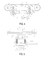
FIG. 4 is an explanatory diagram illustrating a conveyor belt in a side view to which a conveyor belt wear monitoring system of another embodiment of the present technology is applied.
FIG. 5 is an explanatory diagram of the region proximal to the wear detector illustrated in FIG. 4 enlarged.
FIG. 6 is a view taken in the direction of the arrow B in FIG. 5.
DETAILED DESCRIPTION
A conveyor belt wear monitoring system of the present technology will be described below based on embodiments illustrated in the drawings.
A conveyor belt wear monitoring system 1 (referred to below as “system 1”) of an embodiment of the present technology illustrated in FIGS. 1 to 3 is to be applied to a conveyor belt 9 of a functioning conveyor belt line. In a functioning conveyor belt line, an object to be conveyed conveyed by another conveyor belt is fed onto the conveyor belt 9 and conveyed to a conveying destination by the conveyor belt 9. The object to be conveyed may be fed onto the conveyor belt 9 by a hopper and the like. The conveyor belt 9 is mounted on pulleys 10 at a prescribed tension. Between the pulleys 10, the conveyor belt 9 is supported by support rollers 10 a disposed at appropriate intervals in the belt longitudinal direction.
The conveyor belt 9 is constituted by a core layer 9 b including a core made of canvas, steel cord, or the like, and an upper cover rubber 9 a and a lower cover rubber 9 c that sandwich the core layer 9 b therebetween. The core layer 9 b is a member that bears the tension that causes the conveyor belt 9 to be at tension.
The system 1 includes a wear detector 2 that detects the amount of wear of the upper cover rubber 9 a, a control unit 3 that controls the movement of the wear detector 2, and a calculation unit 4 that receives the detection data from the wear detector 2. In this embodiment, the wear detector 2 includes a sensor unit 2 a, and two wear detectors 2 are installed on the return side of the conveyor belt 9 at intervals in the longitudinal direction. The carrying side of the conveyor belt 9 is trough-like, which is why the wear detector 2 is installed on the flat return side. However, the wear detector 2 can be installed at a portion on the carrying side which is flat across the entire belt width if there is such a portion.
Also in this embodiment, the control unit 3 and the calculation unit 4 are independent of each other. However, the control unit 3 and the calculation unit 4 can be integrated. The wear detector 2 is connected with the control unit 3 and the calculation unit 4 via a wired or wireless connection.
The sensor unit 2 a that constitutes a part of the wear detector 2 measures the distance H1 to a surface (conveying surface) S1 of the upper cover rubber 9 a, for example. Examples of the sensor unit 2 a include a laser sensor and an ultrasonic sensor. A sensor unit 2 a that measures the surface condition of the upper cover rubber 9 a in three dimensions can be used instead of the sensor unit 2 a that measures linear distance to obtain more detailed data on the amount of wear.
A rotary roller 6 that rolls in the belt width direction is connected to either sides of the wear detector 2 through a support shaft 5. The rotary roller 6 and the support shaft 5 is moveable in the belt thickness direction relative to the wear detector 2 via suspension 6 a. Additionally, a guide ring 7 b is connected to the lower end portion of the wear detector 2. A guide rod 7 a that extends in the belt width direction is inserted in the guide ring 7 b. The guide rod 7 a and the guide ring 7 b constitute a guide 7 that guides the movement in the belt width direction of the wear detector 2.
A contact member 8 is disposed spaced apart in the belt thickness direction from the rotary roller 6 in contact with the upper cover rubber 9 a. The contact member 8 is in contact with the lower cover rubber 9 c and sandwiches the conveyor belt 9 with the rotary roller 6. In this embodiment, an elongated body that extends across the entire length in the belt width direction is used as the contact member 8. The contact member 8 is made to stand by at a position that does not interfere with the running of the conveyor belt 9. When the amount of wear of the upper cover rubber 9 a is measured, the contact member 8 is placed at a preset position that is a constant position in the vertical direction (position in the belt thickness direction).
Next, the method of detecting the amount of wear of the upper cover rubber 9 a of the conveyor belt 9 employed by the system 1 is described.
In embodiments of the present technology, an amount of wear W of the upper cover rubber 9 a of the conveyor belt 9 is detected while the conveyor belt 9 is not running. The conveyor belt 9 may be stopped routinely or when maintenance and the like is necessary. The amount of wear W is detected during such periods. For example, the amount of wear W is detected every day at night when the conveyor belt 9 is stopped.
In installing the wear detector 2 on the conveyor belt 9, from the standby position, the contact member 8 is brought into contact with the lower cover rubber 9 c at a preset position in the belt circumferential direction with the position in the vertical direction (position in the belt thickness direction) remaining constant. Then, the wear detector 2 is installed corresponding to the contact member 8 to sandwich the conveyor belt 9. Here, the rotary roller 6 is brought into contact with the upper cover rubber 9 a, and the biasing force of the suspension 6 a is adjusted to a strength that does not deform the upper cover rubber 9 a. In such a manner, the rotary roller 6 and the contact member 8 sandwich the conveyor belt 9.
Next, detection of the amount of wear W of the upper cover rubber 9 a is initiated. The control unit 3 controls the wear detector 2 to detect the distance H1 from the sensor unit 2 a to the surface of the upper cover rubber 9 a while the wear detector 2 moves across the entire length in the belt width direction guided by the guide ring 7 b and the guide rod 7 a. Here, the rotary roller 6 rolls in contact with the upper cover rubber 9 a. Once the wear detector 2 moves across the entire length of the belt width, the detection of the distance H1 is terminated. The detection data (the distance H1) from the sensor unit 2 a is received by the calculation unit 4.
The mechanism that moves the wear detector 2 in the belt width direction is not particularly limited and various mechanisms can be employed. For example, the guide rod 7 a and the guide ring 7 b may screw together, and the guide rod 7 a rotates about the axis thereof to move the guide ring 7 b in the longitudinal direction of the guide rod 7 a (belt width direction). Alternatively, the wear detector 2 may be moved in the belt width direction by pulling a wire or the like connected to the wear detector 2.
Next, a method of obtaining the amount of wear W is described based on FIG. 3. Reference sign S1 denotes the position of the surface of the upper cover rubber 9 a that is the current detection target. Reference sign S2 denotes an imaginary line that represents the position of the surface of the upper cover rubber 9 a that is the previous detection target. The vertical position of the upper end of the sensor unit 2 a is defined as reference line C. The reference line C has the same vertical position as the previous detection and remains constant. The contact member 8 also has the same vertical position as the previous detection and remains constant.
A distance H2 of the previous detection from the sensor unit 2 a to the surface of the upper cover rubber 9 a is stored in the calculation unit 4. By subtracting the distance H2 from the currently detected distance H1, the amount of wear W of the upper cover rubber 9 a in the period between the previous detection and the current detection can be obtained. Specifically, amount of wear W=H1−H2. Note that in FIG. 3, H1, H2, and the amount of wear W are illustrated exaggerated in size. Thereafter, the amount of wear W in a desired period can be obtained via a similar process by detecting the distance from the sensor unit 2 a to the surface of the upper cover rubber 9 a in a similar manner.
According to embodiments of the present technology described above, the amount of wear W of the upper cover rubber 9 a is detected when the conveyor belt 9 is stopped, allowing highly accurate detection data to be obtained without errors relating to detection by the wear detector 2 caused by vibrations of the conveyor belt 9 and the like. The amount of wear W in the belt width direction can be obtained, and this means that a distribution of the amount of wear W in the belt width direction can be determined.
Additionally, the wear detector 2 is not subject to vibrations from the running conveyor belt 9, thus greatly reducing the risk of it breaking down. This is a great advantage for embodiments in which a precise wear detector 2 is used.
The wear detector 2 preferably moves back and forth at least across the entire length in the belt width direction. If the wear detector 2 detects the distance H1 (H2) at the same position a plurality of times, the reliability of the detection data can be increased. In such embodiments, the average value of the detection data may be used, for example.
In some embodiments, the rotary roller 6 may not be provided. However, by providing the rotary roller 6, sagging and deformation of the conveyor belt 9 can be suppressed, and thus detection can be carried out with the conveyor belt 9 in a stable state. This is advantageous in obtaining highly accurate detection data. Providing the contact member 8 can also suppress sagging and deformation of the conveyor belt 9, thus further contributing to obtaining highly accurate detection data.
The number of installed wear detectors 2 may be one. However, by installing a plurality of wear detectors 2 to detect the amount of wear W as in this embodiment, an averaged wear condition of the conveyor belt 9 without outliers can be determined. The number of the wear detector 2 is not limited to any particular number, and may range from 2 to 4 for example.
The wear condition of the upper cover rubber 9 a affected by the object to be conveyed is mostly the same at any position in the circumferential direction of the conveyor belt 9 due to the same conditions existing at any position in the circumferential direction of the conveyor belt 9. Accordingly, in embodiments with a plurality of wear detectors 2, when one of the wear detectors 2 detects an implausible value, it can be assumed that there is a high possibility that the wear detector 2 is faulty. Thus, installing a plurality of wear detectors 2 is advantageous in discovering faulty wear detectors 2. Installing three or greater wear detectors 2 further facilitates the discovery of faulty wear detectors 2.
A system 1 according another embodiment of the present technology is illustrated in FIGS. 4 to 6. This embodiment has the same configuration as the previous embodiment except that the wear detector 2 and the contact member 8 are different.
The wear detector 2 of this embodiment includes a sensor unit 2 a and a sensor roller 2 b. The sensor roller 2 b is supported by a support shaft 2 c to be rotatable about the sensor unit 2 a. The support shaft 2 c is moveable in the belt thickness direction via a suspension 2 d incorporated in the sensor unit 2 a. A guide ring 7 b into which a guide rod 7 a is inserted is connected to the lower end portion of the wear detector 2 in a similar manner to that of the previous embodiment. When the amount of wear W is detected, the guide rod 7 a is installed at a preset position that is a constant position in the vertical direction. The sensor unit 2 a detects, for example, a distance H3 from the center of the support shaft 2 c to the center of the guide rod 7 a.
The contact member 8 includes a moving roller 8 a. The moving roller 8 a is supported by a support frame 8 b in a manner allowing for rotation. The support frame 8 b and the moving roller 8 a move along a guide rod 8 c that extends in the belt width direction. The contact member 8 is made to stand by at a position that does not interfere with the running of the conveyor belt 9. When the amount of wear of the upper cover rubber 9 a is measured, the contact member 8 is placed at a preset position that is a constant position in the vertical direction (position in the belt thickness direction).
Next, the method of detecting the amount of wear of the upper cover rubber 9 a of the conveyor belt 9 employed by the system 1 is described.
In installing the wear detector 2 on the stopped conveyor belt 9, the contact member 8 is moved from the standby position and the moving roller 8 a is brought into contact with the lower cover rubber 9 c at a preset position in the belt circumferential direction with the position in the vertical direction (position in the belt thickness direction) remaining constant. Then, the wear detector 2 is installed corresponding to the contact member 8 to sandwich the conveyor belt 9. Here, the sensor roller 2 b is brought into contact with the upper cover rubber 9 a, and the biasing force of the suspension 2 d is adjusted to a strength that does not deform the upper cover rubber 9 a. In such a manner, the sensor roller 2 b and the moving roller 8 a sandwich the conveyor belt 9.
Next, detection of the amount of wear W of the upper cover rubber 9 a is initiated. The control unit 3 controls the wear detector 2 so the sensor unit 2 a detects the distance H3 from the center of the support shaft 2 c to the center of the guide rod 7 a while the wear detector 2 moves across the entire length in the belt width direction guided by the guide ring 7 b and the guide rod 7 a. Here, the sensor roller 2 b rolls in contact with the upper cover rubber 9 a while moving up and down conforming to the surface shape of the upper cover rubber 9 a. Accordingly, the support shaft 2 c also moves up and down conforming to the surface shape of the upper cover rubber 9 a. The moving roller 8 a rolls in contact with the lower cover rubber 9 c at a position corresponding to the sensor roller 2 b while moving in the belt width direction.
Once the wear detector 2 moves across the entire length of the belt width, the detection of the distance H3 is terminated. The detection data (the distance H3) from the sensor unit 2 a is received by the calculation unit 4.
The mechanism that moves the wear detector 2 and the moving roller 8 a (contact member 8) in the belt width direction is not particularly limited and various mechanisms can be employed such as that described for the previous embodiment.
Next, a method of obtaining the amount of wear W is described based on FIG. 6. Reference sign S1 denotes the position of the surface of the upper cover rubber 9 a that is the current detection target. Reference sign S2 denotes an imaginary line that represents the position of the surface of the upper cover rubber 9 a that is the previous detection target. The vertical position of the center of the guide rod 7 a is defined as reference line C. The reference line C has the same vertical position as the previous detection and remains constant. The moving roller 8 a (the contact member 8) also has the same vertical position as the previous detection and remains constant.
A distance H4 of the previous detection by the sensor unit 2 a from the center of the support shaft 2 c to the reference line C is stored in the calculation unit 4. By subtracting the distance H4 from the currently detected distance H3, the amount of wear W of the upper cover rubber 9 a in the period between the previous detection and the current detection can be obtained. Specifically, amount of wear W=H3−H4. Note that in FIG. 6, H3, H4, and the amount of wear W are illustrated exaggerated in size. Thereafter, the amount of wear W in a desired period can be obtained via a similar process by detecting the distance from the center of the support shaft 2 c to the center of the guide rod 7 a in a similar manner.
According to this embodiment, the same effects as the first embodiment can be achieved. In this embodiment, the conveyor belt 9 is sandwiched between the sensor roller 2 b and the moving roller 8 a, suppressing sagging and deformation of the conveyor belt 9. As a result, the amount of wear W of the upper cover rubber 9 a can be detected with high accuracy.
Note that the elongated contact member 8 described in the previous embodiment can also be employed in this embodiment. Additionally, the contact member 8 including the moving roller 8 a described in this embodiment can be employed in the previous embodiment.
In this embodiment, a sensor can be provided which measures the repulsion force on the sensor roller 2 b in contact with the upper cover rubber 9 a. Such a configuration allows the state of deterioration of the upper cover rubber 9 a to be determined on the basis of the measured repulsion force.