US9943635B2 - Extracorporeal circulation device and control method - Google Patents
Extracorporeal circulation device and control method Download PDFInfo
- Publication number
- US9943635B2 US9943635B2 US14/422,484 US201214422484A US9943635B2 US 9943635 B2 US9943635 B2 US 9943635B2 US 201214422484 A US201214422484 A US 201214422484A US 9943635 B2 US9943635 B2 US 9943635B2
- Authority
- US
- United States
- Prior art keywords
- control unit
- main control
- sub
- circuit
- extracorporeal circulation
- Prior art date
- Legal status (The legal status is an assumption and is not a legal conclusion. Google has not performed a legal analysis and makes no representation as to the accuracy of the status listed.)
- Active, expires
Links
Images


Classifications
-
- A—HUMAN NECESSITIES
- A61—MEDICAL OR VETERINARY SCIENCE; HYGIENE
- A61M—DEVICES FOR INTRODUCING MEDIA INTO, OR ONTO, THE BODY; DEVICES FOR TRANSDUCING BODY MEDIA OR FOR TAKING MEDIA FROM THE BODY; DEVICES FOR PRODUCING OR ENDING SLEEP OR STUPOR
- A61M1/00—Suction or pumping devices for medical purposes; Devices for carrying-off, for treatment of, or for carrying-over, body-liquids; Drainage systems
- A61M1/36—Other treatment of blood in a by-pass of the natural circulatory system, e.g. temperature adaptation, irradiation ; Extra-corporeal blood circuits
- A61M1/3621—Extra-corporeal blood circuits
- A61M1/3643—Priming, rinsing before or after use
- A61M1/3644—Mode of operation
-
- A—HUMAN NECESSITIES
- A61—MEDICAL OR VETERINARY SCIENCE; HYGIENE
- A61M—DEVICES FOR INTRODUCING MEDIA INTO, OR ONTO, THE BODY; DEVICES FOR TRANSDUCING BODY MEDIA OR FOR TAKING MEDIA FROM THE BODY; DEVICES FOR PRODUCING OR ENDING SLEEP OR STUPOR
- A61M1/00—Suction or pumping devices for medical purposes; Devices for carrying-off, for treatment of, or for carrying-over, body-liquids; Drainage systems
- A61M1/36—Other treatment of blood in a by-pass of the natural circulatory system, e.g. temperature adaptation, irradiation ; Extra-corporeal blood circuits
- A61M1/3621—Extra-corporeal blood circuits
- A61M1/3666—Cardiac or cardiopulmonary bypass, e.g. heart-lung machines
- A61M1/3667—Cardiac or cardiopulmonary bypass, e.g. heart-lung machines with assisted venous return
-
- A—HUMAN NECESSITIES
- A61—MEDICAL OR VETERINARY SCIENCE; HYGIENE
- A61M—DEVICES FOR INTRODUCING MEDIA INTO, OR ONTO, THE BODY; DEVICES FOR TRANSDUCING BODY MEDIA OR FOR TAKING MEDIA FROM THE BODY; DEVICES FOR PRODUCING OR ENDING SLEEP OR STUPOR
- A61M60/00—Blood pumps; Devices for mechanical circulatory actuation; Balloon pumps for circulatory assistance
- A61M60/10—Location thereof with respect to the patient's body
- A61M60/104—Extracorporeal pumps, i.e. the blood being pumped outside the patient's body
- A61M60/109—Extracorporeal pumps, i.e. the blood being pumped outside the patient's body incorporated within extracorporeal blood circuits or systems
- A61M60/113—Extracorporeal pumps, i.e. the blood being pumped outside the patient's body incorporated within extracorporeal blood circuits or systems in other functional devices, e.g. dialysers or heart-lung machines
-
- A—HUMAN NECESSITIES
- A61—MEDICAL OR VETERINARY SCIENCE; HYGIENE
- A61M—DEVICES FOR INTRODUCING MEDIA INTO, OR ONTO, THE BODY; DEVICES FOR TRANSDUCING BODY MEDIA OR FOR TAKING MEDIA FROM THE BODY; DEVICES FOR PRODUCING OR ENDING SLEEP OR STUPOR
- A61M60/00—Blood pumps; Devices for mechanical circulatory actuation; Balloon pumps for circulatory assistance
- A61M60/20—Type thereof
- A61M60/205—Non-positive displacement blood pumps
- A61M60/216—Non-positive displacement blood pumps including a rotating member acting on the blood, e.g. impeller
- A61M60/226—Non-positive displacement blood pumps including a rotating member acting on the blood, e.g. impeller the blood flow through the rotating member having mainly radial components
- A61M60/232—Centrifugal pumps
-
- A—HUMAN NECESSITIES
- A61—MEDICAL OR VETERINARY SCIENCE; HYGIENE
- A61M—DEVICES FOR INTRODUCING MEDIA INTO, OR ONTO, THE BODY; DEVICES FOR TRANSDUCING BODY MEDIA OR FOR TAKING MEDIA FROM THE BODY; DEVICES FOR PRODUCING OR ENDING SLEEP OR STUPOR
- A61M60/00—Blood pumps; Devices for mechanical circulatory actuation; Balloon pumps for circulatory assistance
- A61M60/30—Medical purposes thereof other than the enhancement of the cardiac output
- A61M60/36—Medical purposes thereof other than the enhancement of the cardiac output for specific blood treatment; for specific therapy
- A61M60/38—Blood oxygenation
-
- A—HUMAN NECESSITIES
- A61—MEDICAL OR VETERINARY SCIENCE; HYGIENE
- A61M—DEVICES FOR INTRODUCING MEDIA INTO, OR ONTO, THE BODY; DEVICES FOR TRANSDUCING BODY MEDIA OR FOR TAKING MEDIA FROM THE BODY; DEVICES FOR PRODUCING OR ENDING SLEEP OR STUPOR
- A61M60/00—Blood pumps; Devices for mechanical circulatory actuation; Balloon pumps for circulatory assistance
- A61M60/40—Details relating to driving
- A61M60/403—Details relating to driving for non-positive displacement blood pumps
- A61M60/422—Details relating to driving for non-positive displacement blood pumps the force acting on the blood contacting member being electromagnetic, e.g. using canned motor pumps
-
- A—HUMAN NECESSITIES
- A61—MEDICAL OR VETERINARY SCIENCE; HYGIENE
- A61M—DEVICES FOR INTRODUCING MEDIA INTO, OR ONTO, THE BODY; DEVICES FOR TRANSDUCING BODY MEDIA OR FOR TAKING MEDIA FROM THE BODY; DEVICES FOR PRODUCING OR ENDING SLEEP OR STUPOR
- A61M60/00—Blood pumps; Devices for mechanical circulatory actuation; Balloon pumps for circulatory assistance
- A61M60/50—Details relating to control
- A61M60/508—Electronic control means, e.g. for feedback regulation
-
- A—HUMAN NECESSITIES
- A61—MEDICAL OR VETERINARY SCIENCE; HYGIENE
- A61M—DEVICES FOR INTRODUCING MEDIA INTO, OR ONTO, THE BODY; DEVICES FOR TRANSDUCING BODY MEDIA OR FOR TAKING MEDIA FROM THE BODY; DEVICES FOR PRODUCING OR ENDING SLEEP OR STUPOR
- A61M60/00—Blood pumps; Devices for mechanical circulatory actuation; Balloon pumps for circulatory assistance
- A61M60/50—Details relating to control
- A61M60/585—User interfaces
-
- A61M1/1006—
-
- A61M1/101—
-
- A61M1/1086—
-
- A—HUMAN NECESSITIES
- A61—MEDICAL OR VETERINARY SCIENCE; HYGIENE
- A61M—DEVICES FOR INTRODUCING MEDIA INTO, OR ONTO, THE BODY; DEVICES FOR TRANSDUCING BODY MEDIA OR FOR TAKING MEDIA FROM THE BODY; DEVICES FOR PRODUCING OR ENDING SLEEP OR STUPOR
- A61M1/00—Suction or pumping devices for medical purposes; Devices for carrying-off, for treatment of, or for carrying-over, body-liquids; Drainage systems
- A61M1/36—Other treatment of blood in a by-pass of the natural circulatory system, e.g. temperature adaptation, irradiation ; Extra-corporeal blood circuits
- A61M1/3621—Extra-corporeal blood circuits
- A61M1/3643—Priming, rinsing before or after use
-
- A—HUMAN NECESSITIES
- A61—MEDICAL OR VETERINARY SCIENCE; HYGIENE
- A61M—DEVICES FOR INTRODUCING MEDIA INTO, OR ONTO, THE BODY; DEVICES FOR TRANSDUCING BODY MEDIA OR FOR TAKING MEDIA FROM THE BODY; DEVICES FOR PRODUCING OR ENDING SLEEP OR STUPOR
- A61M2205/00—General characteristics of the apparatus
- A61M2205/17—General characteristics of the apparatus with redundant control systems
-
- A—HUMAN NECESSITIES
- A61—MEDICAL OR VETERINARY SCIENCE; HYGIENE
- A61M—DEVICES FOR INTRODUCING MEDIA INTO, OR ONTO, THE BODY; DEVICES FOR TRANSDUCING BODY MEDIA OR FOR TAKING MEDIA FROM THE BODY; DEVICES FOR PRODUCING OR ENDING SLEEP OR STUPOR
- A61M2205/00—General characteristics of the apparatus
- A61M2205/33—Controlling, regulating or measuring
- A61M2205/3331—Pressure; Flow
- A61M2205/3334—Measuring or controlling the flow rate
Definitions
- the present invention relates to an extracorporeal circulation device and a control method thereof.
- a cardiopulmonary assist device used for a cardiopulmonary assist is known.
- a blood extracorporeal circulation circuit composed of an oxygenator, centrifugal artificial heart (centrifugal pump), controller, oxygen supply source (oxygen tank), and so forth (see, e.g., Japanese patent 4839030).
- the cardiopulmonary assist device functions in place of the heart and lung of a patient and is required to have high safety so that it may be prevented from falling into a situation in which it stops in an operation.
- One method for ensuring the safety is providing a controller for controlling the respective units configuring the circulation circuit with a duplicated structure with main controller and sub-controller. This is because the sub-controller continues control even if the main controller stops due to any cause.
- the sub-controller transmits a signal to the main controller at adequate timing and makes the determination based on whether or not a response signal thereof can be received from the main controller. That is, the sub-controller determines that the main controller is in the stop state if the response signal cannot be received within a predetermined time.
- the present invention is made in view of the above-described problems and intends to provide an extracorporeal circulation device having high safety while suppressing increases in both the circuit scale and the power consumption, and a control method thereof.
- an extracorporeal circulation device of the present invention has the following condition.
- the extracorporeal circulation device is an extracorporeal circulation device that extracorporeally circulates blood of a subject by using a circulation circuit, and has:
- main control unit that is responsible for control of the extracorporeal circulation device and a sub-control unit that is configured by an FPGA (Field-Programmable Gate Array) and takes over processing relating to extracorporeal circulation in place of the main control unit if the main control unit falls into an abnormal state
- sub-control unit has:
- FIG. 1A is a diagram showing one example of the overall configuration of an extracorporeal circulation device 10 according to a first embodiment of the present invention.
- FIG. 1B is a diagram showing one example of the overall configuration of the extracorporeal circulation device 10 according to the first embodiment of the present invention.
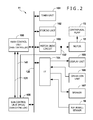
- FIG. 2 is a block configuration diagram of a control device 11 .
- FIG. 3 is a flowchart showing the processing procedure of a main controller in the control device 11 .
- FIG. 4 is a flowchart showing the processing procedure of a sub-controller in the control device 11 .
- FIGS. 1A and 1B are diagrams showing one example of the overall configuration of an extracorporeal circulation device 10 according to a first embodiment of the present invention.
- the extracorporeal circulation device 10 carries out cardiopulmonary assist operation (extracorporeal circulation, assisted circulation) used for performing a procedure called PCPS (percutaneous cardiopulmonary support).
- the extracorporeal circulation device 10 has a blood extracorporeal circulation circuit (hereinafter, referred to as circulation circuit) shown by arrows in the diagrams.
- circulation circuit blood extracorporeal circulation circuit
- the blood of a subject 30 is extracorporeally circulated by using this circulation circuit.
- the priming operation refers to operation of circulating a priming solution (e.g. physiological saline) in the circulation circuit in a state in which the circulation circuit is sufficiently filled with the priming solution to remove air bubbles in this circuit.
- a priming solution e.g. physiological saline
- the extracorporeal circulation device 10 is provided with a control device 11 , a motor 12 , a centrifugal pump 13 driven by this motor 12 , an oxygenator 14 , an oxygen supply source 15 , a catheter (venous side) 16 , a catheter (arterial side) 17 , an air bubble sensor 18 , branching lines 19 , and a blood filter 20 .
- a control device 11 a motor 12 , a centrifugal pump 13 driven by this motor 12 , an oxygenator 14 , an oxygen supply source 15 , a catheter (venous side) 16 , a catheter (arterial side) 17 , an air bubble sensor 18 , branching lines 19 , and a blood filter 20 .
- these respective components are connected by tubes having flexibility or the like and the lumens of these tubes form flow paths of the blood.
- the catheter (arterial side) 17 sends the blood toward the inside of the body of the subject 30 and the catheter (venous side) 16 carries out blood removal from the inside of the body of the subject 30 .
- the centrifugal pump 13 is referred to also as a centrifugal artificial heart. It drives a rotary body provided inside to give a pressure to the blood and circulate the blood in the circulation circuit.
- the motor 12 gives a rotational driving force to the rotary body of the centrifugal pump 13 .
- the oxygenator 14 carries out circulation of the blood and gas exchange of the blood (oxygen addition, carbon dioxide removal, and so forth).
- the oxygen supply source 15 is implemented by, e.g., an oxygen tank or the like and supplies oxygen to be added to the blood.
- the oxygen supplied from the oxygen supply source 15 is used at the time of gas exchange by the oxygenator 14 .
- the air bubble sensor 18 detects air bubbles flowing in the circulation circuit at the time of priming operation by a predetermined detection method (ultrasound, light, etc.).
- the blood filter 20 filters the blood and removes air bubbles in the blood.
- the branching lines 19 switch the flow path of the circulation circuit. Specifically, in the case of extracorporeally circulating the blood of the subject 30 , the branching lines 19 construct a circulation circuit passing through the inside of the body of the subject 30 to circulate the blood outside the body of the subject 30 as shown in FIG. 1A . At the time of priming operation, as shown in FIG. 1B , the routes of the circulation circuit to the inside of the body of the subject 30 are blocked by the branching lines 19 to construct a circulation circuit passing through only the outside of the body of the subject (in other words, circulation circuit that does not pass through the inside of the body of the subject 30 ).
- the inside of the circulation circuit is filled with a priming solution and the priming solution is circulated (without passing through the inside of the body of the subject).
- a priming solution On the circulation circuit, one or plural air bubble expelling ports (not shown) for expelling air bubbles are made.
- air bubbles in the circulation circuit are expelled from these air bubble expelling ports.
- the control device 11 carries out overall control of operation in the extracorporeal circulation device 10 .
- the control device 11 gives a control signal to a drive circuit that controls the motor 12 to drive the centrifugal pump 13 and acquires an air bubble detection result (sensor value) from the air bubble sensor 18 .
- control of the priming operation and so forth are also carried out.
- the control device 11 controls execution of priming operation.
- the circulation circuit that does not pass through the inside of the body of the subject 30 is constructed by the branching lines 19 as shown in FIG. 1B .
- a priming solution supply source 22 is connected to the branching lines 19 and a priming solution is supplied from this priming solution supply source 22 into the circulation circuit. This causes the inside of the circulation circuit to be filled with the priming solution.
- a drive signal is given to the motor 12 under control by the control device 11 and the centrifugal pump 13 is driven to provide a predetermined flow rate, so that plural rounds of circulation of the priming solution in the circulation circuit are caused.
- Air bubbles in the circulation circuit are expelled from the air bubble expelling ports and so forth along with this circulation.
- the air bubbles in the circulation circuit are detected by the air bubble sensor 18 and the control device 11 monitors the state of the air bubbles included in the circulation circuit based on the detection result by this air bubble sensor 18 .
- the control device 11 when detecting that the air bubbles have been cleared off from the inside of the circulation circuit in accordance with a predetermined criterion (details of the predetermined criterion will be described later), the control device 11 ends the priming operation. At this end, the control device 11 notifies the user that the priming operation has ended by using a display unit (not shown), a speaker (not shown), or the like. The user who has received the notification of the end of the priming operation switches the branching lines 19 to reconfigure the circulation circuit so that it passes through the inside of the body of the subject 30 as shown in FIG. 1A . Then, the flow rate of blood is set and the centrifugal pump 13 is driven at the set blood flow rate to extracorporeally circulate the blood of the subject 30 .
- the blood removed from the catheter (venous side) 16 passes through the centrifugal pump 13 to enter the oxygenator 14 .
- oxygenator 14 treatment of gas exchange, i.e. oxygen addition, carbon dioxide removal, and so forth, is performed as described above.
- the blood passes through the blood filter 20 and so forth and the filtered blood is sent from the catheter (arterial side) 17 to the inside of the body of the subject 30 .
- This treatment from blood removal to blood sending is repeatedly performed, so that the blood of the subject 30 is extracorporeally circulated.
- the control device 11 has a main control unit (main controller) 100 that is responsible for control of the whole device, a timer unit 101 , a storing unit 102 , and a motor drive circuit 103 that applies a drive signal of the motor 12 . Furthermore, the control device 11 has a display unit 105 , an operation unit (i.e., operator interface) 106 , a speaker 107 , and the air bubble sensor 18 and they are connected to a system bus 120 via an interface 104 . Moreover, the control device 11 has a sub-control unit 150 that is responsible for control of the whole of the control device 11 in place of the main control unit 100 if the main control unit 100 has stopped or has failed to normally function due to any cause.
- main controller main controller
- the main control unit 100 is composed of CPU, ROM, and RAM similarly to a normal extracorporeal circulation device. Furthermore, the main control unit 100 and the sub-control unit 150 are connected by a signal line 131 for communicating with each other. In addition, in order to monitor whether the motor drive circuit 103 is outputting a signal corresponding to a blood flow rate set for the motor 12 , the sub-control unit 150 is connected to a signal line 132 for receiving the drive signal. Note that, if the motor 12 is of such a type as to be driven by an applied voltage, an A/D converter for detecting the voltage is incorporated in the sub-control unit 150 . Moreover, in the embodiment, if the main control unit 100 has become an abnormal state due to any cause, the sub-control unit 150 generates a control signal which is provided to main control unit 100 by a signal line 141 for completely stopping the main control unit 100 .
- control device 11 in the embodiment suppresses increase in the complexity of the circuit scale and prevents increase in the power consumption with respect to existing devices. Furthermore, second, the control device 11 continues to make blood flow with the set amount of fluid sending per unit time even when the main control unit 100 falls into an abnormal state.
- the above-described first task is realized by implementing the sub-control unit 150 in the embodiment by an FPGA (Field-Programmable Gate Array).
- FPGA Field-Programmable Gate Array
- the following configuration is employed. Specifically, if the drive signal applied from the motor drive circuit 103 to the motor 12 of the centrifugal pump 13 does not fall within an allowable range commensurate with the set flow rate, the main control unit 100 is deemed to be in an abnormal state and the sub-control unit 150 takes over the role of it.
- FIG. 3 shows the processing procedure carried out by the main control unit 100 in the embodiment.
- a program relating to this diagram is stored in the storing unit 102 .
- processing as shown is subsequent to reception of an instruction to start priming treatment from the operation unit 106 .
- the main control unit 100 notifies the sub-control unit 150 that the priming treatment is started via the signal line 131 in a step S 101 , and performs the priming treatment in a step S 102 .
- the priming treatment as described above, in the state in which the circulation circuit that does not pass through the inside of the body of the subject 30 has been constructed by the branching lines 19 as shown in FIG. 1B , a control signal to generate the drive signal for circulating a priming solution at a preset flow rate is output to the motor drive circuit 103 . Because the circulation circuit is constructed outside the body of the subject 30 , the motor drive circuit 103 at this time may set the flow rate by the centrifugal pump 13 to the maximum rate.
- the main control unit 100 continues the priming treatment until determining in a step S 103 that the inside of the circulation circuit is filled with the priming solution and air bubbles have been expelled based on a signal from the air bubble sensor 18 .
- the processing proceeds to a step S 104 and the main control unit 100 notifies the sub-control unit 150 that the priming treatment has been ended. Then, in the step S 104 , the main control unit 100 sets a blood flow rate S B to be used while blood is actually circulated. Upon the setting of the blood flow rate S B , the main control unit 100 notifies the sub-control unit 150 of the set blood flow rate S B in a step S 105 .
- the branching lines 19 are switched to make the configuration of FIG. 1A and, in a step S 106 , the main control unit 100 controls the motor drive circuit 103 so that the blood flow rate S B set from the operation unit 106 may be obtained, and performs extracorporeal circulation treatment. Then, the main control unit 100 repeats the processing of the step S 106 until determining in a step S 107 that an instruction to end the operation and stop the extracorporeal circulation has been made from the operation unit 106 . If determining that the end instruction has been made, the main control unit 100 notifies the sub-control unit 150 that the blood circulation treatment has ended and ends the present processing.
- a program to execute the processing procedure relating to the flowchart of this diagram is stored in the sub-control unit (FPGA) 150 .
- the sub-control unit 150 waits for receiving a notification of the start of priming from the main control unit 100 (corresponding to S 101 in FIG. 3 ). Upon receiving the notification of the start of priming treatment, the sub-control unit 150 detects a drive voltage signal applied to the motor 12 via the signal line 132 and detects its voltage level (for which A/D conversion is performed). Then, the sub-control unit 150 compares the detected voltage value V with an allowable range between upper and lower voltage values [V PL , V PH ] at the time of the priming treatment and determines whether or not the following condition expression (1) is satisfied. V PL ⁇ V ⁇ V PH (1)
- the sub-control unit 150 deems that the priming is being normally performed and waits for reception of a notification of the end of the priming.
- the sub-control unit 150 deems the main control unit 100 to be in the stop or abnormal state due to any cause and the processing proceeds to a step S 204 .
- the sub-control unit 150 forcibly stops the main control unit 100 via the signal line 141 and assumes control of the display unit 105 , the operation unit 106 , the speaker 107 , the air bubble sensor 18 , the motor drive circuit 103 , and so forth via various commands issued over system bus 120 by sub-control unit 150 . Thereafter, the sub-control unit 150 takes over the processing of the priming treatment and the subsequent steps. Because the priming treatment and the subsequent steps are as already described by using FIG. 3 , detailed description thereof is omitted.
- the sub-control unit 150 forwards the processing to a step S 206 and receives the blood flow rate S B set by a user from the main control unit 100 (corresponding to the step S 105 in FIG. 3 ). Thereafter, in a step S 207 , the sub-control unit 150 decides an allowable range [V BL , V BH ] of the drive voltage applied to the motor 12 for yielding the received blood flow rate S B .
- a lookup table in which the blood flow rates S B and the lower limit and upper limit values of the allowable drive voltage are stored may be stored in the sub-control unit 150 and the allowable range [V BL , V BH ] may be derived with reference to it.
- step S 208 the sub-control unit 150 detects the drive voltage V to the motor 12 via the signal line 132 in the subsequent blood circulation treatment. Furthermore, the sub-control unit 150 determines whether or not the following condition expression (2) is satisfied and keeps on monitoring the progression of the blood circulation treatment with keeping of satisfaction of this condition expression (2). V BL ⁇ V ⁇ V BH (2) If receiving a notification of end from the main control unit 100 with this state having been maintained (corresponding to the step S 108 in FIG. 3 ), the sub-control unit 150 ends the present processing.
- the sub-control unit 150 deems the main control unit 100 to be in the stop or abnormal state due to any cause and the processing proceeds to a step S 210 .
- the sub-control unit 150 forcibly stops the main control unit 100 via the signal line 141 and sets the display unit 105 , the operation unit 106 , the speaker 107 , the air bubble sensor 18 , the motor drive circuit 103 , and so forth under control of the sub-control unit 150 . Thereafter, the sub-control unit 150 takes over the blood circulation treatment. Because the blood circulation treatment is as already described by using FIG. 3 , detailed description thereof is omitted.
- the present invention is not limited to the embodiment shown in the above description and the drawings and can be so carried out as to be modified as appropriate within such a range as not to change the gist thereof.
- the configuration is so made that the centrifugal pump 13 monitors the voltage applied to its motor 12 .
- the motor 12 is of such a type as to be capable of changing the blood flow rate based on the number of pulses per unit time, it suffices to determine whether or not the number of pulses per unit time falls within an allowable range.
Landscapes
- Health & Medical Sciences (AREA)
- Heart & Thoracic Surgery (AREA)
- Engineering & Computer Science (AREA)
- Cardiology (AREA)
- Veterinary Medicine (AREA)
- Public Health (AREA)
- Biomedical Technology (AREA)
- Hematology (AREA)
- Life Sciences & Earth Sciences (AREA)
- Animal Behavior & Ethology (AREA)
- General Health & Medical Sciences (AREA)
- Anesthesiology (AREA)
- Vascular Medicine (AREA)
- Mechanical Engineering (AREA)
- Pulmonology (AREA)
- Emergency Medicine (AREA)
- Human Computer Interaction (AREA)
- External Artificial Organs (AREA)
Abstract
An extracorporeal circulation device having high safety without increases in the circuit scale and the power consumption includes a main control unit responsible for control of a motor drive circuit so as to yield a blood flow rate per unit time set by a user. The motor drive circuit applies a drive signal corresponding to the set blood flow rate to a motor. A sub-control unit configured by a field programmable gate array (FPGA) detects the drive signal applied to the motor and monitors whether or not the drive signal falls within an allowable range corresponding to the set blood flow rate. If the drive signal outside the allowable range is applied, the main control unit is deemed to be in an abnormal state and the main control unit is completely stopped. Then, the sub-control unit takes over the subsequent processing.
Description
The present invention relates to an extracorporeal circulation device and a control method thereof.
Conventionally, as a representative one of extracorporeal circulation devices, a cardiopulmonary assist device used for a cardiopulmonary assist is known. Such a device is provided with a blood extracorporeal circulation circuit composed of an oxygenator, centrifugal artificial heart (centrifugal pump), controller, oxygen supply source (oxygen tank), and so forth (see, e.g., Japanese patent 4839030).
The cardiopulmonary assist device functions in place of the heart and lung of a patient and is required to have high safety so that it may be prevented from falling into a situation in which it stops in an operation.
One method for ensuring the safety is providing a controller for controlling the respective units configuring the circulation circuit with a duplicated structure with main controller and sub-controller. This is because the sub-controller continues control even if the main controller stops due to any cause. To determine whether or not the main controller is in the stop state, the sub-controller transmits a signal to the main controller at adequate timing and makes the determination based on whether or not a response signal thereof can be received from the main controller. That is, the sub-controller determines that the main controller is in the stop state if the response signal cannot be received within a predetermined time.
As described above, doubling the controller allows construction of a safer system. However, on the other hand, there is a problem that the circuit scale becomes more complicated and increases in the device size and the power consumption are caused.
Furthermore, particularly in the case of artificial heart and lung, during an operation, it is important that the blood flows with an amount of fluid matching the amount per unit time as commanded by a doctor or a person performing the operation. Therefore, even if the main controller issues an erroneous control signal to a drive unit for the centrifugal pump due to any cause, this has not been detected by the prior art as an abnormality.
The present invention is made in view of the above-described problems and intends to provide an extracorporeal circulation device having high safety while suppressing increases in both the circuit scale and the power consumption, and a control method thereof.
To solve the above-described problems, an extracorporeal circulation device of the present invention has the following condition. Specifically, the extracorporeal circulation device is an extracorporeal circulation device that extracorporeally circulates blood of a subject by using a circulation circuit, and has:
a main control unit that is responsible for control of the extracorporeal circulation device and a sub-control unit that is configured by an FPGA (Field-Programmable Gate Array) and takes over processing relating to extracorporeal circulation in place of the main control unit if the main control unit falls into an abnormal state,
wherein the sub-control unit has:
-
- monitoring means that monitors a drive signal applied to a motor of a pump for performing the extracorporeal circulation of the blood,
- determining means that determines whether the main control unit is in a normal state or is in an abnormal state by determining whether or not the drive signal falls within an allowable range for yielding a set amount of fluid sending per unit time during monitoring by the monitoring means, and
- treatment means that takes over and handles treatment relating to blood circulation in place of the main control unit if it is determined that the main control unit is in an abnormal state by the determining means.
According to the present invention, it becomes possible to provide an extracorporeal circulation device having high safety while suppressing increases in both the circuit scale and the power consumption.
Other characteristics and advantages of the present invention will become apparent based on the following description with reference to the accompanying drawings. Note that the same or similar configuration is given the same reference numeral in the accompanying drawings.
Accompanying drawings are included in the specification and configure part thereof, and are used to show embodiments of the present invention and explain the principle of the present invention together with description of the embodiments.
1. Overall Configuration of Extracorporeal Circulation Device
The extracorporeal circulation device 10 carries out cardiopulmonary assist operation (extracorporeal circulation, assisted circulation) used for performing a procedure called PCPS (percutaneous cardiopulmonary support). The extracorporeal circulation device 10 has a blood extracorporeal circulation circuit (hereinafter, referred to as circulation circuit) shown by arrows in the diagrams. In the extracorporeal circulation device 10, after priming operation is carried out, the blood of a subject 30 is extracorporeally circulated by using this circulation circuit.
Here, the priming operation refers to operation of circulating a priming solution (e.g. physiological saline) in the circulation circuit in a state in which the circulation circuit is sufficiently filled with the priming solution to remove air bubbles in this circuit.
The extracorporeal circulation device 10 is provided with a control device 11, a motor 12, a centrifugal pump 13 driven by this motor 12, an oxygenator 14, an oxygen supply source 15, a catheter (venous side) 16, a catheter (arterial side) 17, an air bubble sensor 18, branching lines 19, and a blood filter 20. Note that these respective components are connected by tubes having flexibility or the like and the lumens of these tubes form flow paths of the blood.
The catheter (arterial side) 17 sends the blood toward the inside of the body of the subject 30 and the catheter (venous side) 16 carries out blood removal from the inside of the body of the subject 30.
The centrifugal pump 13 is referred to also as a centrifugal artificial heart. It drives a rotary body provided inside to give a pressure to the blood and circulate the blood in the circulation circuit. The motor 12 gives a rotational driving force to the rotary body of the centrifugal pump 13.
The oxygenator 14 carries out circulation of the blood and gas exchange of the blood (oxygen addition, carbon dioxide removal, and so forth). The oxygen supply source 15 is implemented by, e.g., an oxygen tank or the like and supplies oxygen to be added to the blood. The oxygen supplied from the oxygen supply source 15 is used at the time of gas exchange by the oxygenator 14.
The air bubble sensor 18 detects air bubbles flowing in the circulation circuit at the time of priming operation by a predetermined detection method (ultrasound, light, etc.). The blood filter 20 filters the blood and removes air bubbles in the blood.
The branching lines 19 switch the flow path of the circulation circuit. Specifically, in the case of extracorporeally circulating the blood of the subject 30, the branching lines 19 construct a circulation circuit passing through the inside of the body of the subject 30 to circulate the blood outside the body of the subject 30 as shown in FIG. 1A . At the time of priming operation, as shown in FIG. 1B , the routes of the circulation circuit to the inside of the body of the subject 30 are blocked by the branching lines 19 to construct a circulation circuit passing through only the outside of the body of the subject (in other words, circulation circuit that does not pass through the inside of the body of the subject 30). Furthermore, the inside of the circulation circuit is filled with a priming solution and the priming solution is circulated (without passing through the inside of the body of the subject). On the circulation circuit, one or plural air bubble expelling ports (not shown) for expelling air bubbles are made. By causing plural rounds of circulation of the priming solution in the circulation circuit, air bubbles in the circulation circuit are expelled from these air bubble expelling ports.
The control device 11 carries out overall control of operation in the extracorporeal circulation device 10. For example, the control device 11 gives a control signal to a drive circuit that controls the motor 12 to drive the centrifugal pump 13 and acquires an air bubble detection result (sensor value) from the air bubble sensor 18. Besides, in the control device 11, control of the priming operation and so forth are also carried out.
Here, a brief description will be made about the flow of treatment when the blood of the subject 30 is extracorporeally circulated by using the extracorporeal circulation device 10 shown in FIGS. 1A and 1B .
At the start of this treatment, the control device 11 controls execution of priming operation. At the time of the priming operation, the circulation circuit that does not pass through the inside of the body of the subject 30 is constructed by the branching lines 19 as shown in FIG. 1B . For example, at this time, a priming solution supply source 22 is connected to the branching lines 19 and a priming solution is supplied from this priming solution supply source 22 into the circulation circuit. This causes the inside of the circulation circuit to be filled with the priming solution.
Then, a drive signal is given to the motor 12 under control by the control device 11 and the centrifugal pump 13 is driven to provide a predetermined flow rate, so that plural rounds of circulation of the priming solution in the circulation circuit are caused. Air bubbles in the circulation circuit are expelled from the air bubble expelling ports and so forth along with this circulation. At this time, the air bubbles in the circulation circuit are detected by the air bubble sensor 18 and the control device 11 monitors the state of the air bubbles included in the circulation circuit based on the detection result by this air bubble sensor 18.
Here, when detecting that the air bubbles have been cleared off from the inside of the circulation circuit in accordance with a predetermined criterion (details of the predetermined criterion will be described later), the control device 11 ends the priming operation. At this end, the control device 11 notifies the user that the priming operation has ended by using a display unit (not shown), a speaker (not shown), or the like. The user who has received the notification of the end of the priming operation switches the branching lines 19 to reconfigure the circulation circuit so that it passes through the inside of the body of the subject 30 as shown in FIG. 1A . Then, the flow rate of blood is set and the centrifugal pump 13 is driven at the set blood flow rate to extracorporeally circulate the blood of the subject 30.
Upon the start of the extracorporeal circulation, the blood removed from the catheter (venous side) 16 passes through the centrifugal pump 13 to enter the oxygenator 14. In the oxygenator 14, treatment of gas exchange, i.e. oxygen addition, carbon dioxide removal, and so forth, is performed as described above. Thereafter, the blood passes through the blood filter 20 and so forth and the filtered blood is sent from the catheter (arterial side) 17 to the inside of the body of the subject 30. This treatment from blood removal to blood sending is repeatedly performed, so that the blood of the subject 30 is extracorporeally circulated.
The above is the description about one example of the overall configuration of the extracorporeal circulation device 10 relating to the present embodiment and the flow of treatment of extracorporeal circulation. Note that the configuration of the extracorporeal circulation device 10 shown in FIGS. 1A and 1B is absolutely one example and the configuration may be changed as appropriate. For example, a reservoir (blood is stored) may be provided.
2. Functional Configuration of Control Device
Next, the configuration of the control device 11 shown in FIG. 1A will be described by using FIG. 2 .
The control device 11 has a main control unit (main controller) 100 that is responsible for control of the whole device, a timer unit 101, a storing unit 102, and a motor drive circuit 103 that applies a drive signal of the motor 12. Furthermore, the control device 11 has a display unit 105, an operation unit (i.e., operator interface) 106, a speaker 107, and the air bubble sensor 18 and they are connected to a system bus 120 via an interface 104. Moreover, the control device 11 has a sub-control unit 150 that is responsible for control of the whole of the control device 11 in place of the main control unit 100 if the main control unit 100 has stopped or has failed to normally function due to any cause.
The main control unit 100 is composed of CPU, ROM, and RAM similarly to a normal extracorporeal circulation device. Furthermore, the main control unit 100 and the sub-control unit 150 are connected by a signal line 131 for communicating with each other. In addition, in order to monitor whether the motor drive circuit 103 is outputting a signal corresponding to a blood flow rate set for the motor 12, the sub-control unit 150 is connected to a signal line 132 for receiving the drive signal. Note that, if the motor 12 is of such a type as to be driven by an applied voltage, an A/D converter for detecting the voltage is incorporated in the sub-control unit 150. Moreover, in the embodiment, if the main control unit 100 has become an abnormal state due to any cause, the sub-control unit 150 generates a control signal which is provided to main control unit 100 by a signal line 141 for completely stopping the main control unit 100.
3. Processing Procedures of Main and Sub-Control Units
First, the control device 11 in the embodiment suppresses increase in the complexity of the circuit scale and prevents increase in the power consumption with respect to existing devices. Furthermore, second, the control device 11 continues to make blood flow with the set amount of fluid sending per unit time even when the main control unit 100 falls into an abnormal state.
The above-described first task is realized by implementing the sub-control unit 150 in the embodiment by an FPGA (Field-Programmable Gate Array).
Furthermore, as for the second task, the following configuration is employed. Specifically, if the drive signal applied from the motor drive circuit 103 to the motor 12 of the centrifugal pump 13 does not fall within an allowable range commensurate with the set flow rate, the main control unit 100 is deemed to be in an abnormal state and the sub-control unit 150 takes over the role of it.
Further explanation will be unnecessary for those skilled in the art about the implementation by the FPGA for solving the above-described first task. Therefore, in the following, the processing procedures of the main control unit 100 and the sub-control unit 150 in the embodiment for solving the above-described second task will be described in more detail with reference to FIGS. 3 and 4 .
Note that processing as shown is subsequent to reception of an instruction to start priming treatment from the operation unit 106.
First, the main control unit 100 notifies the sub-control unit 150 that the priming treatment is started via the signal line 131 in a step S101, and performs the priming treatment in a step S102. In the priming treatment, as described above, in the state in which the circulation circuit that does not pass through the inside of the body of the subject 30 has been constructed by the branching lines 19 as shown in FIG. 1B , a control signal to generate the drive signal for circulating a priming solution at a preset flow rate is output to the motor drive circuit 103. Because the circulation circuit is constructed outside the body of the subject 30, the motor drive circuit 103 at this time may set the flow rate by the centrifugal pump 13 to the maximum rate. The main control unit 100 continues the priming treatment until determining in a step S103 that the inside of the circulation circuit is filled with the priming solution and air bubbles have been expelled based on a signal from the air bubble sensor 18.
Then, if the main control unit 100 determines that air bubbles have been expelled from the circulation circuit, the processing proceeds to a step S104 and the main control unit 100 notifies the sub-control unit 150 that the priming treatment has been ended. Then, in the step S104, the main control unit 100 sets a blood flow rate SB to be used while blood is actually circulated. Upon the setting of the blood flow rate SB, the main control unit 100 notifies the sub-control unit 150 of the set blood flow rate SB in a step S105.
Thereafter, the branching lines 19 are switched to make the configuration of FIG. 1A and, in a step S106, the main control unit 100 controls the motor drive circuit 103 so that the blood flow rate SB set from the operation unit 106 may be obtained, and performs extracorporeal circulation treatment. Then, the main control unit 100 repeats the processing of the step S106 until determining in a step S107 that an instruction to end the operation and stop the extracorporeal circulation has been made from the operation unit 106. If determining that the end instruction has been made, the main control unit 100 notifies the sub-control unit 150 that the blood circulation treatment has ended and ends the present processing.
Next, the processing procedure of the sub-control unit 150 in the embodiment will be described in accordance with a flowchart of FIG. 4 . A program to execute the processing procedure relating to the flowchart of this diagram is stored in the sub-control unit (FPGA) 150.
First, in a step S201, the sub-control unit 150 waits for receiving a notification of the start of priming from the main control unit 100 (corresponding to S101 in FIG. 3 ). Upon receiving the notification of the start of priming treatment, the sub-control unit 150 detects a drive voltage signal applied to the motor 12 via the signal line 132 and detects its voltage level (for which A/D conversion is performed). Then, the sub-control unit 150 compares the detected voltage value V with an allowable range between upper and lower voltage values [VPL, VPH] at the time of the priming treatment and determines whether or not the following condition expression (1) is satisfied.
V PL ≤V≤V PH (1)
V PL ≤V≤V PH (1)
Then, if determining that the voltage value falls within this range, the sub-control unit 150 deems that the priming is being normally performed and waits for reception of a notification of the end of the priming.
If the main control unit 100 enters a state in which the above condition expression (1) is not satisfied before the notification of the end of the priming is received, the sub-control unit 150 deems the main control unit 100 to be in the stop or abnormal state due to any cause and the processing proceeds to a step S204. In the step S204, the sub-control unit 150 forcibly stops the main control unit 100 via the signal line 141 and assumes control of the display unit 105, the operation unit 106, the speaker 107, the air bubble sensor 18, the motor drive circuit 103, and so forth via various commands issued over system bus 120 by sub-control unit 150. Thereafter, the sub-control unit 150 takes over the processing of the priming treatment and the subsequent steps. Because the priming treatment and the subsequent steps are as already described by using FIG. 3 , detailed description thereof is omitted.
On the other hand, if the notification of the end of the priming treatment is received (corresponding to S104 in FIG. 3 ) with the above condition expression (1) kept satisfied, the sub-control unit 150 forwards the processing to a step S206 and receives the blood flow rate SB set by a user from the main control unit 100 (corresponding to the step S105 in FIG. 3 ). Thereafter, in a step S207, the sub-control unit 150 decides an allowable range [VBL, VBH] of the drive voltage applied to the motor 12 for yielding the received blood flow rate SB. For this decision, a lookup table in which the blood flow rates SB and the lower limit and upper limit values of the allowable drive voltage are stored may be stored in the sub-control unit 150 and the allowable range [VBL, VBH] may be derived with reference to it.
Thereafter, the processing proceeds to a step S208, where the sub-control unit 150 detects the drive voltage V to the motor 12 via the signal line 132 in the subsequent blood circulation treatment. Furthermore, the sub-control unit 150 determines whether or not the following condition expression (2) is satisfied and keeps on monitoring the progression of the blood circulation treatment with keeping of satisfaction of this condition expression (2).
V BL ≤V≤V BH (2)
If receiving a notification of end from themain control unit 100 with this state having been maintained (corresponding to the step S108 in FIG. 3 ), the sub-control unit 150 ends the present processing.
V BL ≤V≤V BH (2)
If receiving a notification of end from the
On the other hand, if the drive voltage V to the motor 12 via the signal line 132 does not satisfy the above condition expression (2) in the blood circulation treatment, i.e. if the drive signal outside the allowable range is applied (including also the case in which the applied voltage is zero), the sub-control unit 150 deems the main control unit 100 to be in the stop or abnormal state due to any cause and the processing proceeds to a step S210. In the step S210, the sub-control unit 150 forcibly stops the main control unit 100 via the signal line 141 and sets the display unit 105, the operation unit 106, the speaker 107, the air bubble sensor 18, the motor drive circuit 103, and so forth under control of the sub-control unit 150. Thereafter, the sub-control unit 150 takes over the blood circulation treatment. Because the blood circulation treatment is as already described by using FIG. 3 , detailed description thereof is omitted.
As described above, according to the present embodiment, it becomes possible to configure an extracorporeal circulation device having high safety while suppressing increases in both the circuit scale and the power consumption.
The above is an example of a representative embodiment of the present invention. However, the present invention is not limited to the embodiment shown in the above description and the drawings and can be so carried out as to be modified as appropriate within such a range as not to change the gist thereof. In particular, in the embodiment, the configuration is so made that the centrifugal pump 13 monitors the voltage applied to its motor 12. However, if the motor 12 is of such a type as to be capable of changing the blood flow rate based on the number of pulses per unit time, it suffices to determine whether or not the number of pulses per unit time falls within an allowable range.
The present invention is not limited to the above-described embodiment and various changes and modifications are possible without departing from the gist and scope of the present invention. Therefore, the following claims are attached for determining the scope of the present invention.
Claims (3)
1. An extracorporeal circulation device that extracorporeally circulates blood of a subject by using a circulation circuit, the extracorporeal circulation device comprising:
a main control unit controlling the extracorporeal circulation device and a sub-control unit comprised of an FPGA (Field-Programmable Gate Array) configured to take over processing relating to extracorporeal circulation in place of the main control unit if the main control unit falls into an abnormal state,
wherein the main control unit includes an input connected to a signal line for receiving a control signal to stop the main control unit;
wherein the sub-control unit includes:
a monitoring circuit that monitors a drive signal applied by the main control unit to a motor of a pump for performing the extracorporeal circulation of the blood,
a decision circuit that determines whether the main control unit is in a normal state or is in an abnormal state by determining whether or not the drive signal falls within an allowable range for yielding a set amount of fluid sending per unit time during monitoring by the monitoring circuit, and
a control circuit that takes over and handles treatment relating to blood circulation in place of the main control unit if it is determined that the main control unit is in the abnormal state by the decision circuit, wherein the control circuit is coupled to the signal line to send the control signal in order to forcibly stop the main control unit when the main control unit falls into the abnormal state.
2. The extracorporeal circulation device according to claim 1 ,
wherein the main control unit includes:
a notification circuit that notifies the sub-control unit of a start and an end of a period of priming treatment for the extracorporeal circulation device, and
wherein the sub-control unit includes:
a second decision circuit that determines whether or not the drive signal falls within a preset allowable range for the priming treatment from reception of a notification of priming start until reception of a notification of end, and
a second control circuit that takes over and handles the priming treatment in place of the main control unit if it is determined that the drive signal falls outside the allowable range by the second decision circuit, wherein the second control circuit is coupled to the signal line to send the control signal in order to forcibly stop the main control unit when the drive signal falls outside the allowable range.
3. A control method of an extracorporeal circulation device having a main control unit that is responsible for control of the device and a sub-control unit that is configured by an FPGA (Field-Programmable Gate Array) and takes over processing relating to extracorporeal circulation in place of the main control unit if the main control unit falls into an abnormal state in order to extracorporeally circulate blood of a subject by using a circulation circuit, the control method comprising the steps of:
monitoring a drive signal applied to a motor of a pump for performing the extracorporeal circulation of the blood;
determining whether the main control unit is in a normal state or is in an abnormal state by determining whether or not the drive signal falls within an allowable range for yielding a set amount of fluid sending per unit time during monitoring by the monitoring step;
the sub-control unit forcibly stopping operation of the main control unit if it is determined that the main control unit is in an abnormal state in the determining step; and
the sub-control unit taking over treatment relating to blood circulation in place of the main control unit if it is determined that the main control unit is in an abnormal state in the determining step.
Applications Claiming Priority (1)
| Application Number | Priority Date | Filing Date | Title |
|---|---|---|---|
| PCT/JP2012/005611 WO2014037971A1 (en) | 2012-09-05 | 2012-09-05 | Extracorporeal circulation device and control method therefor |
Publications (2)
| Publication Number | Publication Date |
|---|---|
| US20150202358A1 US20150202358A1 (en) | 2015-07-23 |
| US9943635B2 true US9943635B2 (en) | 2018-04-17 |
Family
ID=50236625
Family Applications (1)
| Application Number | Title | Priority Date | Filing Date |
|---|---|---|---|
| US14/422,484 Active 2033-04-16 US9943635B2 (en) | 2012-09-05 | 2012-09-05 | Extracorporeal circulation device and control method |
Country Status (4)
| Country | Link |
|---|---|
| US (1) | US9943635B2 (en) |
| EP (1) | EP2893944B1 (en) |
| JP (1) | JP5913598B2 (en) |
| WO (1) | WO2014037971A1 (en) |
Families Citing this family (1)
| Publication number | Priority date | Publication date | Assignee | Title |
|---|---|---|---|---|
| CN114306791B (en) * | 2021-12-23 | 2024-06-18 | 上海宏创医疗科技有限公司 | Control host for extracorporeal circulation equipment |
Citations (6)
| Publication number | Priority date | Publication date | Assignee | Title |
|---|---|---|---|---|
| US6123726A (en) * | 1997-07-25 | 2000-09-26 | Seiko Epson Corporation | Portable drive system for artificial heart |
| US6808508B1 (en) * | 2000-09-13 | 2004-10-26 | Cardiacassist, Inc. | Method and system for closed chest blood flow support |
| JP2007014504A (en) | 2005-07-06 | 2007-01-25 | Terumo Corp | Extracorporeal circulation apparatus |
| US20070055908A1 (en) | 2005-09-06 | 2007-03-08 | Honda Elesys Co., Ltd. | Redundant power supply circuit and motor driving circuit |
| WO2010065398A1 (en) | 2008-12-04 | 2010-06-10 | Therox, Inc. | Method and device for combined detection of bubbles and flow rate in a system for enriching a bodily fluid with a gas |
| US20110015732A1 (en) | 2008-03-25 | 2011-01-20 | Sun Medical Technology Research Corporation | Auxiliary artificial heart pump drive device and auxiliary artifical heart system |
Family Cites Families (8)
| Publication number | Priority date | Publication date | Assignee | Title |
|---|---|---|---|---|
| US4298938A (en) * | 1980-01-28 | 1981-11-03 | Baxter Travenol Laboratories, Inc. | Backup control circuit for kidney dialysis machine |
| JPS62249655A (en) * | 1986-03-31 | 1987-10-30 | アイシン精機株式会社 | Auxiliary recirculation machinery driving apparatus |
| IT1250558B (en) * | 1991-12-30 | 1995-04-20 | Hospal Dasco Spa | DIALYSIS MACHINE WITH SAFETY CONTROL AND RELATED SAFETY CONTROL METHOD. |
| JPH1085322A (en) * | 1996-07-26 | 1998-04-07 | San Medical Gijutsu Kenkyusho:Kk | Portable driving system for artificial heart |
| DE19849787C1 (en) * | 1998-10-28 | 2000-02-24 | Fresenius Medical Care De Gmbh | Dialysis machine includes distributed operational and auxiliary computers with bus interconnections, sensors and actuators in high-integrity redundant architecture safeguarding life-critical systems |
| DE102005013418A1 (en) * | 2005-03-23 | 2006-09-28 | B. Braun Medizintechnologie Gmbh | Blood treatment device with alarm device |
| JP4584095B2 (en) * | 2005-09-22 | 2010-11-17 | 株式会社ホンダエレシス | Motor drive circuit |
| US8597505B2 (en) * | 2007-09-13 | 2013-12-03 | Fresenius Medical Care Holdings, Inc. | Portable dialysis machine |
-
2012
- 2012-09-05 EP EP12884094.9A patent/EP2893944B1/en active Active
- 2012-09-05 WO PCT/JP2012/005611 patent/WO2014037971A1/en active Application Filing
- 2012-09-05 US US14/422,484 patent/US9943635B2/en active Active
- 2012-09-05 JP JP2014534042A patent/JP5913598B2/en active Active
Patent Citations (6)
| Publication number | Priority date | Publication date | Assignee | Title |
|---|---|---|---|---|
| US6123726A (en) * | 1997-07-25 | 2000-09-26 | Seiko Epson Corporation | Portable drive system for artificial heart |
| US6808508B1 (en) * | 2000-09-13 | 2004-10-26 | Cardiacassist, Inc. | Method and system for closed chest blood flow support |
| JP2007014504A (en) | 2005-07-06 | 2007-01-25 | Terumo Corp | Extracorporeal circulation apparatus |
| US20070055908A1 (en) | 2005-09-06 | 2007-03-08 | Honda Elesys Co., Ltd. | Redundant power supply circuit and motor driving circuit |
| US20110015732A1 (en) | 2008-03-25 | 2011-01-20 | Sun Medical Technology Research Corporation | Auxiliary artificial heart pump drive device and auxiliary artifical heart system |
| WO2010065398A1 (en) | 2008-12-04 | 2010-06-10 | Therox, Inc. | Method and device for combined detection of bubbles and flow rate in a system for enriching a bodily fluid with a gas |
Also Published As
| Publication number | Publication date |
|---|---|
| JPWO2014037971A1 (en) | 2016-08-08 |
| WO2014037971A1 (en) | 2014-03-13 |
| EP2893944A1 (en) | 2015-07-15 |
| US20150202358A1 (en) | 2015-07-23 |
| JP5913598B2 (en) | 2016-04-27 |
| EP2893944A4 (en) | 2016-04-27 |
| EP2893944B1 (en) | 2017-10-25 |
Similar Documents
| Publication | Publication Date | Title |
|---|---|---|
| JP2019055267A (en) | Blood purification device and priming method thereof | |
| JP6517023B2 (en) | Blood purification device | |
| JP6005844B2 (en) | Circulation device and control method thereof | |
| AU769974B2 (en) | Mobile heart-lung machine | |
| WO2006054367A1 (en) | Automatic reinfusing system | |
| JP2009536537A (en) | How to fill and clean blood tube sets | |
| US20190262521A1 (en) | Device for extracorporeal blood treatment involving a change of concentrate | |
| JP5851616B2 (en) | Control device, circulation device and control method | |
| JP2008012210A (en) | Priming method and apparatus of hemodialyzer | |
| JP2018525091A (en) | Portable ultrafiltration unit and device for supplying dialysate to ultrafiltration unit | |
| JP5160975B2 (en) | Blood purification equipment | |
| JP5301259B2 (en) | Hemodialysis machine | |
| US9943635B2 (en) | Extracorporeal circulation device and control method | |
| JP6170603B2 (en) | Circulation device and control method thereof | |
| JP5869684B2 (en) | Controller for life support apparatus and control method thereof | |
| JP5852248B2 (en) | Extracorporeal circulation device, control device and control method thereof | |
| WO2014162358A1 (en) | Extracorporeal circulation device | |
| JP5947450B2 (en) | Circulation device, control device and information processing method | |
| WO2014162359A1 (en) | Extracorporeal circulation device, and control method and storage medium for extracorporeal circulation device | |
| JP2013017580A (en) | Extracorporeal circulation device and priming method of the same | |
| WO2023226109A1 (en) | Extracorporeal circulation system of blood purification apparatus, and automatic pre-washing method thereof | |
| JP6517081B2 (en) | Blood purification device | |
| JPWO2018030353A1 (en) | Blood purification apparatus and priming method |
Legal Events
| Date | Code | Title | Description |
|---|---|---|---|
| AS | Assignment |
Owner name: TERUMO KABUSHIKI KAISHA, JAPAN Free format text: ASSIGNMENT OF ASSIGNORS INTEREST;ASSIGNOR:IWATA, TAKEHARU;REEL/FRAME:034984/0610 Effective date: 20150218 |
|
| STCF | Information on status: patent grant |
Free format text: PATENTED CASE |
|
| MAFP | Maintenance fee payment |
Free format text: PAYMENT OF MAINTENANCE FEE, 4TH YEAR, LARGE ENTITY (ORIGINAL EVENT CODE: M1551); ENTITY STATUS OF PATENT OWNER: LARGE ENTITY Year of fee payment: 4 |