US9932227B2 - Production of graphene from metal alkoxide - Google Patents
Production of graphene from metal alkoxide Download PDFInfo
- Publication number
- US9932227B2 US9932227B2 US13/384,881 US201013384881A US9932227B2 US 9932227 B2 US9932227 B2 US 9932227B2 US 201013384881 A US201013384881 A US 201013384881A US 9932227 B2 US9932227 B2 US 9932227B2
- Authority
- US
- United States
- Prior art keywords
- graphene
- process according
- metal alkoxide
- metal
- region
- Prior art date
- Legal status (The legal status is an assumption and is not a legal conclusion. Google has not performed a legal analysis and makes no representation as to the accuracy of the status listed.)
- Active, expires
Links
- OKTJSMMVPCPJKN-UHFFFAOYSA-N Carbon Chemical compound [C] OKTJSMMVPCPJKN-UHFFFAOYSA-N 0.000 title claims abstract description 212
- 229910021389 graphene Inorganic materials 0.000 title claims abstract description 179
- 229910052751 metal Inorganic materials 0.000 title claims abstract description 99
- 239000002184 metal Substances 0.000 title claims abstract description 99
- 150000004703 alkoxides Chemical class 0.000 title claims abstract description 75
- 238000004519 manufacturing process Methods 0.000 title description 25
- 238000000034 method Methods 0.000 claims abstract description 130
- 230000008569 process Effects 0.000 claims abstract description 100
- 238000000354 decomposition reaction Methods 0.000 claims abstract description 20
- 238000005979 thermal decomposition reaction Methods 0.000 claims abstract description 17
- 239000002904 solvent Substances 0.000 claims abstract description 11
- LFQSCWFLJHTTHZ-UHFFFAOYSA-N Ethanol Chemical compound CCO LFQSCWFLJHTTHZ-UHFFFAOYSA-N 0.000 claims description 107
- 239000003153 chemical reaction reagent Substances 0.000 claims description 31
- 239000000843 powder Substances 0.000 claims description 29
- 239000000758 substrate Substances 0.000 claims description 24
- 239000007921 spray Substances 0.000 claims description 18
- 239000011734 sodium Substances 0.000 claims description 15
- VYPSYNLAJGMNEJ-UHFFFAOYSA-N Silicium dioxide Chemical compound O=[Si]=O VYPSYNLAJGMNEJ-UHFFFAOYSA-N 0.000 claims description 12
- XLYOFNOQVPJJNP-UHFFFAOYSA-N water Substances O XLYOFNOQVPJJNP-UHFFFAOYSA-N 0.000 claims description 11
- BVKZGUZCCUSVTD-UHFFFAOYSA-L Carbonate Chemical compound [O-]C([O-])=O BVKZGUZCCUSVTD-UHFFFAOYSA-L 0.000 claims description 10
- 238000005229 chemical vapour deposition Methods 0.000 claims description 10
- 229910052708 sodium Inorganic materials 0.000 claims description 10
- 239000000443 aerosol Substances 0.000 claims description 9
- 238000000137 annealing Methods 0.000 claims description 9
- 239000003595 mist Substances 0.000 claims description 9
- DGAQECJNVWCQMB-PUAWFVPOSA-M Ilexoside XXIX Chemical compound C[C@@H]1CC[C@@]2(CC[C@@]3(C(=CC[C@H]4[C@]3(CC[C@@H]5[C@@]4(CC[C@@H](C5(C)C)OS(=O)(=O)[O-])C)C)[C@@H]2[C@]1(C)O)C)C(=O)O[C@H]6[C@@H]([C@H]([C@@H]([C@H](O6)CO)O)O)O.[Na+] DGAQECJNVWCQMB-PUAWFVPOSA-M 0.000 claims description 8
- 125000000217 alkyl group Chemical group 0.000 claims description 7
- 229910000000 metal hydroxide Inorganic materials 0.000 claims description 7
- 150000004692 metal hydroxides Chemical class 0.000 claims description 7
- 229910052814 silicon oxide Inorganic materials 0.000 claims description 7
- 229910052710 silicon Inorganic materials 0.000 claims description 5
- 239000010703 silicon Substances 0.000 claims description 5
- HBMJWWWQQXIZIP-UHFFFAOYSA-N silicon carbide Chemical compound [Si+]#[C-] HBMJWWWQQXIZIP-UHFFFAOYSA-N 0.000 claims description 5
- 229910010271 silicon carbide Inorganic materials 0.000 claims description 5
- 238000005406 washing Methods 0.000 claims description 4
- 239000011521 glass Substances 0.000 claims description 3
- 238000004729 solvothermal method Methods 0.000 claims description 3
- HHFAWKCIHAUFRX-UHFFFAOYSA-N ethoxide Chemical compound CC[O-] HHFAWKCIHAUFRX-UHFFFAOYSA-N 0.000 claims description 2
- -1 sodium alkoxide Chemical class 0.000 claims description 2
- 239000000243 solution Substances 0.000 description 48
- HEMHJVSKTPXQMS-UHFFFAOYSA-M Sodium hydroxide Chemical compound [OH-].[Na+] HEMHJVSKTPXQMS-UHFFFAOYSA-M 0.000 description 39
- 239000010408 film Substances 0.000 description 33
- CDBYLPFSWZWCQE-UHFFFAOYSA-L Sodium Carbonate Chemical compound [Na+].[Na+].[O-]C([O-])=O CDBYLPFSWZWCQE-UHFFFAOYSA-L 0.000 description 32
- QDRKDTQENPPHOJ-UHFFFAOYSA-N sodium ethoxide Chemical compound [Na+].CC[O-] QDRKDTQENPPHOJ-UHFFFAOYSA-N 0.000 description 27
- 239000007789 gas Substances 0.000 description 20
- XKRFYHLGVUSROY-UHFFFAOYSA-N Argon Chemical compound [Ar] XKRFYHLGVUSROY-UHFFFAOYSA-N 0.000 description 18
- 229910052799 carbon Inorganic materials 0.000 description 18
- 239000000463 material Substances 0.000 description 16
- 229910000029 sodium carbonate Inorganic materials 0.000 description 16
- 230000008901 benefit Effects 0.000 description 11
- 239000002245 particle Substances 0.000 description 11
- 238000005507 spraying Methods 0.000 description 11
- 238000000746 purification Methods 0.000 description 10
- 239000007787 solid Substances 0.000 description 10
- 229910052786 argon Inorganic materials 0.000 description 9
- 239000000047 product Substances 0.000 description 9
- 239000003054 catalyst Substances 0.000 description 8
- 238000006243 chemical reaction Methods 0.000 description 8
- 239000006227 byproduct Substances 0.000 description 7
- 239000002041 carbon nanotube Substances 0.000 description 7
- 229910021393 carbon nanotube Inorganic materials 0.000 description 7
- 229910002804 graphite Inorganic materials 0.000 description 7
- 239000010439 graphite Substances 0.000 description 7
- 238000010438 heat treatment Methods 0.000 description 7
- 239000011261 inert gas Substances 0.000 description 7
- 239000010410 layer Substances 0.000 description 7
- 238000004833 X-ray photoelectron spectroscopy Methods 0.000 description 6
- 230000015572 biosynthetic process Effects 0.000 description 6
- 238000002411 thermogravimetry Methods 0.000 description 6
- 238000004630 atomic force microscopy Methods 0.000 description 5
- 229910052760 oxygen Inorganic materials 0.000 description 5
- 239000010453 quartz Substances 0.000 description 5
- 238000001878 scanning electron micrograph Methods 0.000 description 5
- XMWRBQBLMFGWIX-UHFFFAOYSA-N C60 fullerene Chemical class C12=C3C(C4=C56)=C7C8=C5C5=C9C%10=C6C6=C4C1=C1C4=C6C6=C%10C%10=C9C9=C%11C5=C8C5=C8C7=C3C3=C7C2=C1C1=C2C4=C6C4=C%10C6=C9C9=C%11C5=C5C8=C3C3=C7C1=C1C2=C4C6=C2C9=C5C3=C12 XMWRBQBLMFGWIX-UHFFFAOYSA-N 0.000 description 4
- XUIMIQQOPSSXEZ-UHFFFAOYSA-N Silicon Chemical compound [Si] XUIMIQQOPSSXEZ-UHFFFAOYSA-N 0.000 description 4
- 229910003472 fullerene Inorganic materials 0.000 description 4
- 229910052723 transition metal Inorganic materials 0.000 description 4
- 150000003624 transition metals Chemical class 0.000 description 4
- RYGMFSIKBFXOCR-UHFFFAOYSA-N Copper Chemical compound [Cu] RYGMFSIKBFXOCR-UHFFFAOYSA-N 0.000 description 3
- VEXZGXHMUGYJMC-UHFFFAOYSA-N Hydrochloric acid Chemical compound Cl VEXZGXHMUGYJMC-UHFFFAOYSA-N 0.000 description 3
- WQDUMFSSJAZKTM-UHFFFAOYSA-N Sodium methoxide Chemical compound [Na+].[O-]C WQDUMFSSJAZKTM-UHFFFAOYSA-N 0.000 description 3
- 229910000831 Steel Inorganic materials 0.000 description 3
- QVGXLLKOCUKJST-UHFFFAOYSA-N atomic oxygen Chemical compound [O] QVGXLLKOCUKJST-UHFFFAOYSA-N 0.000 description 3
- 229910052802 copper Inorganic materials 0.000 description 3
- 239000010949 copper Substances 0.000 description 3
- 238000005516 engineering process Methods 0.000 description 3
- 239000007788 liquid Substances 0.000 description 3
- 230000003647 oxidation Effects 0.000 description 3
- 238000007254 oxidation reaction Methods 0.000 description 3
- 239000001301 oxygen Substances 0.000 description 3
- 238000000197 pyrolysis Methods 0.000 description 3
- 230000009467 reduction Effects 0.000 description 3
- 239000010959 steel Substances 0.000 description 3
- OAKJQQAXSVQMHS-UHFFFAOYSA-N Hydrazine Chemical compound NN OAKJQQAXSVQMHS-UHFFFAOYSA-N 0.000 description 2
- UFHFLCQGNIYNRP-UHFFFAOYSA-N Hydrogen Chemical compound [H][H] UFHFLCQGNIYNRP-UHFFFAOYSA-N 0.000 description 2
- PXHVJJICTQNCMI-UHFFFAOYSA-N Nickel Chemical compound [Ni] PXHVJJICTQNCMI-UHFFFAOYSA-N 0.000 description 2
- 238000001237 Raman spectrum Methods 0.000 description 2
- 239000012298 atmosphere Substances 0.000 description 2
- 238000010923 batch production Methods 0.000 description 2
- 239000002717 carbon nanostructure Substances 0.000 description 2
- 239000012159 carrier gas Substances 0.000 description 2
- 230000015556 catabolic process Effects 0.000 description 2
- 238000010924 continuous production Methods 0.000 description 2
- 230000007547 defect Effects 0.000 description 2
- 238000006731 degradation reaction Methods 0.000 description 2
- 238000010894 electron beam technology Methods 0.000 description 2
- 238000000724 energy-dispersive X-ray spectrum Methods 0.000 description 2
- 230000005284 excitation Effects 0.000 description 2
- 239000002360 explosive Substances 0.000 description 2
- KWIUHFFTVRNATP-UHFFFAOYSA-N glycine betaine Chemical compound C[N+](C)(C)CC([O-])=O KWIUHFFTVRNATP-UHFFFAOYSA-N 0.000 description 2
- PCHJSUWPFVWCPO-UHFFFAOYSA-N gold Chemical compound [Au] PCHJSUWPFVWCPO-UHFFFAOYSA-N 0.000 description 2
- 229910052737 gold Inorganic materials 0.000 description 2
- 239000010931 gold Substances 0.000 description 2
- 238000002173 high-resolution transmission electron microscopy Methods 0.000 description 2
- 239000001257 hydrogen Substances 0.000 description 2
- 229910052739 hydrogen Inorganic materials 0.000 description 2
- 238000011065 in-situ storage Methods 0.000 description 2
- 238000002347 injection Methods 0.000 description 2
- 239000007924 injection Substances 0.000 description 2
- 238000011835 investigation Methods 0.000 description 2
- 239000007791 liquid phase Substances 0.000 description 2
- 239000011777 magnesium Substances 0.000 description 2
- VNWKTOKETHGBQD-UHFFFAOYSA-N methane Chemical compound C VNWKTOKETHGBQD-UHFFFAOYSA-N 0.000 description 2
- 239000002808 molecular sieve Substances 0.000 description 2
- 239000002071 nanotube Substances 0.000 description 2
- 239000004033 plastic Substances 0.000 description 2
- 239000013014 purified material Substances 0.000 description 2
- 229910052709 silver Inorganic materials 0.000 description 2
- 239000004332 silver Substances 0.000 description 2
- URGAHOPLAPQHLN-UHFFFAOYSA-N sodium aluminosilicate Chemical compound [Na+].[Al+3].[O-][Si]([O-])=O.[O-][Si]([O-])=O URGAHOPLAPQHLN-UHFFFAOYSA-N 0.000 description 2
- 238000004611 spectroscopical analysis Methods 0.000 description 2
- 239000006228 supernatant Substances 0.000 description 2
- 239000004094 surface-active agent Substances 0.000 description 2
- 239000000725 suspension Substances 0.000 description 2
- 238000003786 synthesis reaction Methods 0.000 description 2
- DSSYKIVIOFKYAU-XCBNKYQSSA-N (R)-camphor Chemical compound C1C[C@@]2(C)C(=O)C[C@@H]1C2(C)C DSSYKIVIOFKYAU-XCBNKYQSSA-N 0.000 description 1
- 241000723346 Cinnamomum camphora Species 0.000 description 1
- 230000005355 Hall effect Effects 0.000 description 1
- WHXSMMKQMYFTQS-UHFFFAOYSA-N Lithium Chemical compound [Li] WHXSMMKQMYFTQS-UHFFFAOYSA-N 0.000 description 1
- FYYHWMGAXLPEAU-UHFFFAOYSA-N Magnesium Chemical group [Mg] FYYHWMGAXLPEAU-UHFFFAOYSA-N 0.000 description 1
- 239000004677 Nylon Substances 0.000 description 1
- ZLMJMSJWJFRBEC-UHFFFAOYSA-N Potassium Chemical compound [K] ZLMJMSJWJFRBEC-UHFFFAOYSA-N 0.000 description 1
- KEAYESYHFKHZAL-UHFFFAOYSA-N Sodium Chemical compound [Na] KEAYESYHFKHZAL-UHFFFAOYSA-N 0.000 description 1
- QAOWNCQODCNURD-UHFFFAOYSA-N Sulfuric acid Chemical compound OS(O)(=O)=O QAOWNCQODCNURD-UHFFFAOYSA-N 0.000 description 1
- 238000003917 TEM image Methods 0.000 description 1
- 238000000026 X-ray photoelectron spectrum Methods 0.000 description 1
- 239000002390 adhesive tape Substances 0.000 description 1
- 150000001298 alcohols Chemical class 0.000 description 1
- 229910052783 alkali metal Inorganic materials 0.000 description 1
- 150000001340 alkali metals Chemical class 0.000 description 1
- 230000004075 alteration Effects 0.000 description 1
- 238000004458 analytical method Methods 0.000 description 1
- 125000004429 atom Chemical group 0.000 description 1
- 238000000089 atomic force micrograph Methods 0.000 description 1
- 229960003237 betaine Drugs 0.000 description 1
- 125000000484 butyl group Chemical group [H]C([*])([H])C([H])([H])C([H])([H])C([H])([H])[H] 0.000 description 1
- 229960000846 camphor Drugs 0.000 description 1
- 229930008380 camphor Natural products 0.000 description 1
- 125000004432 carbon atom Chemical group C* 0.000 description 1
- 239000006229 carbon black Substances 0.000 description 1
- 150000005323 carbonate salts Chemical class 0.000 description 1
- 150000004649 carbonic acid derivatives Chemical class 0.000 description 1
- 239000002800 charge carrier Substances 0.000 description 1
- 238000003776 cleavage reaction Methods 0.000 description 1
- 239000004020 conductor Substances 0.000 description 1
- 238000004320 controlled atmosphere Methods 0.000 description 1
- 238000005520 cutting process Methods 0.000 description 1
- 238000000151 deposition Methods 0.000 description 1
- 230000001627 detrimental effect Effects 0.000 description 1
- 238000011161 development Methods 0.000 description 1
- 230000008034 disappearance Effects 0.000 description 1
- 239000006185 dispersion Substances 0.000 description 1
- 230000005685 electric field effect Effects 0.000 description 1
- 125000001495 ethyl group Chemical group [H]C([H])([H])C([H])([H])* 0.000 description 1
- 238000004299 exfoliation Methods 0.000 description 1
- 238000002474 experimental method Methods 0.000 description 1
- 239000000945 filler Substances 0.000 description 1
- 238000001914 filtration Methods 0.000 description 1
- 239000008246 gaseous mixture Substances 0.000 description 1
- 229910001385 heavy metal Inorganic materials 0.000 description 1
- 229930195733 hydrocarbon Natural products 0.000 description 1
- 150000002430 hydrocarbons Chemical group 0.000 description 1
- XLYOFNOQVPJJNP-UHFFFAOYSA-M hydroxide Chemical compound [OH-] XLYOFNOQVPJJNP-UHFFFAOYSA-M 0.000 description 1
- 238000007689 inspection Methods 0.000 description 1
- 239000012212 insulator Substances 0.000 description 1
- 230000003993 interaction Effects 0.000 description 1
- 238000009830 intercalation Methods 0.000 description 1
- 230000002687 intercalation Effects 0.000 description 1
- 229910052744 lithium Inorganic materials 0.000 description 1
- 229910052749 magnesium Inorganic materials 0.000 description 1
- 238000005259 measurement Methods 0.000 description 1
- 239000012528 membrane Substances 0.000 description 1
- 239000002923 metal particle Substances 0.000 description 1
- 125000002496 methyl group Chemical group [H]C([H])([H])* 0.000 description 1
- 239000010445 mica Substances 0.000 description 1
- 229910052618 mica group Inorganic materials 0.000 description 1
- 239000000203 mixture Substances 0.000 description 1
- 238000012986 modification Methods 0.000 description 1
- 230000004048 modification Effects 0.000 description 1
- 229910021392 nanocarbon Inorganic materials 0.000 description 1
- 239000002114 nanocomposite Substances 0.000 description 1
- 239000002086 nanomaterial Substances 0.000 description 1
- 230000007935 neutral effect Effects 0.000 description 1
- 229910052759 nickel Inorganic materials 0.000 description 1
- 229920001778 nylon Polymers 0.000 description 1
- 230000020477 pH reduction Effects 0.000 description 1
- 239000002798 polar solvent Substances 0.000 description 1
- 239000011148 porous material Substances 0.000 description 1
- 229910052700 potassium Inorganic materials 0.000 description 1
- 239000011591 potassium Substances 0.000 description 1
- 239000012286 potassium permanganate Substances 0.000 description 1
- 238000002360 preparation method Methods 0.000 description 1
- 125000001436 propyl group Chemical group [H]C([*])([H])C([H])([H])C([H])([H])[H] 0.000 description 1
- 238000010992 reflux Methods 0.000 description 1
- 238000011160 research Methods 0.000 description 1
- 150000003839 salts Chemical class 0.000 description 1
- 239000000523 sample Substances 0.000 description 1
- 238000013341 scale-up Methods 0.000 description 1
- 238000004626 scanning electron microscopy Methods 0.000 description 1
- 230000007017 scission Effects 0.000 description 1
- 238000000926 separation method Methods 0.000 description 1
- 239000002356 single layer Substances 0.000 description 1
- 159000000000 sodium salts Chemical class 0.000 description 1
- 239000012265 solid product Substances 0.000 description 1
- 238000001228 spectrum Methods 0.000 description 1
- 239000001117 sulphuric acid Substances 0.000 description 1
- 235000011149 sulphuric acid Nutrition 0.000 description 1
- 239000010409 thin film Substances 0.000 description 1
- 238000004627 transmission electron microscopy Methods 0.000 description 1
- 239000012498 ultrapure water Substances 0.000 description 1
- 238000003828 vacuum filtration Methods 0.000 description 1
Images


Classifications
-
- C—CHEMISTRY; METALLURGY
- C01—INORGANIC CHEMISTRY
- C01B—NON-METALLIC ELEMENTS; COMPOUNDS THEREOF; METALLOIDS OR COMPOUNDS THEREOF NOT COVERED BY SUBCLASS C01C
- C01B32/00—Carbon; Compounds thereof
- C01B32/15—Nano-sized carbon materials
- C01B32/182—Graphene
- C01B32/184—Preparation
- C01B32/186—Preparation by chemical vapour deposition [CVD]
-
- B—PERFORMING OPERATIONS; TRANSPORTING
- B82—NANOTECHNOLOGY
- B82Y—SPECIFIC USES OR APPLICATIONS OF NANOSTRUCTURES; MEASUREMENT OR ANALYSIS OF NANOSTRUCTURES; MANUFACTURE OR TREATMENT OF NANOSTRUCTURES
- B82Y40/00—Manufacture or treatment of nanostructures
-
- B—PERFORMING OPERATIONS; TRANSPORTING
- B01—PHYSICAL OR CHEMICAL PROCESSES OR APPARATUS IN GENERAL
- B01J—CHEMICAL OR PHYSICAL PROCESSES, e.g. CATALYSIS OR COLLOID CHEMISTRY; THEIR RELEVANT APPARATUS
- B01J6/00—Heat treatments such as Calcining; Fusing ; Pyrolysis
- B01J6/008—Pyrolysis reactions
-
- B—PERFORMING OPERATIONS; TRANSPORTING
- B82—NANOTECHNOLOGY
- B82Y—SPECIFIC USES OR APPLICATIONS OF NANOSTRUCTURES; MEASUREMENT OR ANALYSIS OF NANOSTRUCTURES; MANUFACTURE OR TREATMENT OF NANOSTRUCTURES
- B82Y30/00—Nanotechnology for materials or surface science, e.g. nanocomposites
-
- C—CHEMISTRY; METALLURGY
- C01—INORGANIC CHEMISTRY
- C01B—NON-METALLIC ELEMENTS; COMPOUNDS THEREOF; METALLOIDS OR COMPOUNDS THEREOF NOT COVERED BY SUBCLASS C01C
- C01B32/00—Carbon; Compounds thereof
- C01B32/15—Nano-sized carbon materials
- C01B32/182—Graphene
- C01B32/184—Preparation
-
- C—CHEMISTRY; METALLURGY
- C01—INORGANIC CHEMISTRY
- C01B—NON-METALLIC ELEMENTS; COMPOUNDS THEREOF; METALLOIDS OR COMPOUNDS THEREOF NOT COVERED BY SUBCLASS C01C
- C01B32/00—Carbon; Compounds thereof
- C01B32/15—Nano-sized carbon materials
- C01B32/182—Graphene
- C01B32/194—After-treatment
- C01B32/196—Purification
-
- C—CHEMISTRY; METALLURGY
- C23—COATING METALLIC MATERIAL; COATING MATERIAL WITH METALLIC MATERIAL; CHEMICAL SURFACE TREATMENT; DIFFUSION TREATMENT OF METALLIC MATERIAL; COATING BY VACUUM EVAPORATION, BY SPUTTERING, BY ION IMPLANTATION OR BY CHEMICAL VAPOUR DEPOSITION, IN GENERAL; INHIBITING CORROSION OF METALLIC MATERIAL OR INCRUSTATION IN GENERAL
- C23C—COATING METALLIC MATERIAL; COATING MATERIAL WITH METALLIC MATERIAL; SURFACE TREATMENT OF METALLIC MATERIAL BY DIFFUSION INTO THE SURFACE, BY CHEMICAL CONVERSION OR SUBSTITUTION; COATING BY VACUUM EVAPORATION, BY SPUTTERING, BY ION IMPLANTATION OR BY CHEMICAL VAPOUR DEPOSITION, IN GENERAL
- C23C16/00—Chemical coating by decomposition of gaseous compounds, without leaving reaction products of surface material in the coating, i.e. chemical vapour deposition [CVD] processes
- C23C16/22—Chemical coating by decomposition of gaseous compounds, without leaving reaction products of surface material in the coating, i.e. chemical vapour deposition [CVD] processes characterised by the deposition of inorganic material, other than metallic material
- C23C16/26—Deposition of carbon only
-
- C—CHEMISTRY; METALLURGY
- C01—INORGANIC CHEMISTRY
- C01B—NON-METALLIC ELEMENTS; COMPOUNDS THEREOF; METALLOIDS OR COMPOUNDS THEREOF NOT COVERED BY SUBCLASS C01C
- C01B2204/00—Structure or properties of graphene
- C01B2204/04—Specific amount of layers or specific thickness
-
- C—CHEMISTRY; METALLURGY
- C01—INORGANIC CHEMISTRY
- C01B—NON-METALLIC ELEMENTS; COMPOUNDS THEREOF; METALLOIDS OR COMPOUNDS THEREOF NOT COVERED BY SUBCLASS C01C
- C01B2204/00—Structure or properties of graphene
- C01B2204/20—Graphene characterized by its properties
- C01B2204/22—Electronic properties
Definitions
- the present invention relates to methods of production of graphene.
- the invention relates to a method of production of graphene using a chemical vapour deposition technique.
- Graphene may be produced according to this process as a powder or a film.
- Graphene is the name given to a two dimensional (2D) monolayer of carbon atoms, in which the atoms are bonded to each other in a 2D hexagonal lattice structure.
- Graphene can be considered to be the basic building block of various other forms of carbon: graphite consists of layers of graphene stacked to form a three dimensional (3D) material, carbon nanotubes are commonly described as rolled-up sheets of graphene, and fullerenes are nanometer-sized balls of graphene.
- Carbon nanostructures have been proposed for use in many different applications, particularly in nanotechnology and materials science. Carbon nanotubes and fullerenes have been used for various applications, but their electric, magnetic and elastic properties all originate from the parent structure. However, graphene has yet to receive the attention that has been thrust upon both nanotubes and fullerenes, due to the problem of making it in bulk quantities for realistic applications. Both fullerenes and carbon nanotubes can be grown by a number of different methods that can be utilized for continuous synthesis. However, existing methods for creating graphene are not viable for industrial or mass production.
- Electrons in graphene behave like relativistic particles that have no rest mass and travel at 10 6 meters per second. This value is 300 times slower than the speed of light in a vacuum but is much faster than electrons travelling in an ordinary conducting material.
- Graphene exhibits a room temperature quantum Hall effect, and an ambipolar electric field effect, as well as the ballistic conduction of charge carriers.
- Graphene is a material suggested as a solution to the problem of transistors based on a silicon oxide gate. Unlike all other known materials, graphene remains highly stable and conductive even when it is cut into devices one nanometer wide. Graphene transistors begin to show advantages and good performance at thicknesses below 10 nanometers—the miniaturization limit at which current silicon technology is expected to fail.
- a graphene layer has also been demonstrated as a conducting transparent electrode in a device.
- WO 2009/029984 A1 describes a process for producing graphene wherein an alkali metal is reacted with an alcohol to produce a solvothermal product comprising a metal alkoxide. The solvothermal product is then pyrolysed to produce the graphene.
- a drawback of this process is that the reaction to form the solvothermal product, on which the process relies, is a lengthy process, taking about 72 hours.
- both the production of the solvothermal product and the pyrolysis step are necessarily performed as a batch process. As a result, the process is not well-suited to industrial-scale manufacture.
- this process produces a high yield of graphene compared with prior art methods, and can be implemented as a continuous process.
- the process can be implemented using available spray injection chemical vapour deposition technology, and is scalable for research-scale or industrial-scale production of graphene.
- Another advantage is that the process can be used to produce both films and powders of graphene.
- the graphene produced is easily isolated, since the metal carbonate and the metal hydroxide byproducts are water-soluble.
- Yet another advantage of the process is that the carbon obtained by thermal decomposition of the alkoxide is substantially all graphene.
- the solvent comprises an alcohol.
- the alkyl group of the alcohol is the same as the alkyl group of the metal alkoxide.
- the alcohol may comprise ethanol, and the metal alkoxide may comprise a metal ethoxide.
- the metal alkoxide may comprise a sodium alkoxide.
- the process may further comprise the step of vaporising the solution.
- the step of introducing the solution may include creating droplets of the metal alkoxide solution.
- the droplets may comprise a spray or mist or aerosol of the metal alkoxide solution.
- the droplets may be created in, or introduced to, a flow of gas.
- the gas is inert.
- the process may further comprise the step of flowing the gas through the first region.
- the process may further comprise the step of flowing the gas through a second region, cooler than the first region, for collecting graphene.
- this step enables the graphene to be collected continuously.
- Graphene powder may be produced.
- the process may further comprise the step of growing a film of graphene on a substrate.
- the substrate is a metal catalyst that is essential to the growth of graphene.
- the present invention does not rely on any particular composition of the substrate for graphene growth.
- the substrate may comprise any material, provided that it is capable of withstanding the conditions used during the process.
- the substrate may comprise a metal, in particular a non-catalytically active metal such as gold, silver, or steel.
- the substrate may comprise a high-temperature plastic.
- the substrate may comprise at least one of: silicon, silicon oxide, glass and/or silicon carbide.
- the present invention enables a graphene film to be grown directly onto a substrate suitable for producing electronics components.
- the process may further comprise the step of controlling the duration of growth of the film.
- controlling the duration of growth of the film enables the thickness of the film to be selected.
- the first region may be held at a temperature above the decomposition point temperature of the metal alkoxide.
- the first region may be held at a temperature in the range 300 to 1800 degrees Celsius.
- the process may include a chemical vapour deposition process.
- the process can be carried out using existing set-ups, as it shares similar technology to that used for production of other carbon nanostructures such as carbon nanotubes.
- the process is operated substantially continuously.
- the process may further comprise the step of washing the graphene with water to remove other products of the thermal decomposition step.
- the process may further comprise the step of annealing the graphene.
- the step of annealing the graphene may be performed at a temperature between 400 and 3000 degrees Celsius.
- the metal alkoxide solution may be obtained by a method other than a solvothermal process.
- the metal alkoxide solution may be obtained using at least one of the following steps:
- each of these methods produce a solution of the metal alkoxide, and it is not necessary to isolate the metal alkoxide.
- a particular advantage in obtaining a metal alkoxide solution by adding a metal carbonate to an alcohol or adding a metal hydroxide to an alcohol, particularly if large quantities of solution are to be produced, is that they do not require using sodium which is very reactive and can therefore be dangerous, and is difficult to store safely.
- metal alkoxides are industrially produced is this manner, and are therefore readily available and inexpensive.
- it is not necessary to produce the metal alkoxide by means of a lengthy and expensive solvothermal process.
- said first region has a sufficiently high temperature to cause thermal decomposition of the metal alkoxide to produce graphene.
- producing a metal alkoxide for decomposition to graphene in situ enables the method to be carried out in a continuous manner.
- the formation of the metal alkoxide and its thermal decomposition to graphene can be carried out simultaneously in the same apparatus.
- the first reagent may comprise at least one of: a metal, a metal carbonate, and/or a metal hydroxide; and said second reagent may comprise an alcohol.
- the metal may comprise sodium.
- the alcohol may comprise ethanol.
- the first reagent may be replenished intermittently.
- this enables the process to be carried out substantially continuously, particularly in the case in which the first reagent is a solid.
- the second reagent may be introduced as droplets into the decomposition apparatus.
- this allows the second reagent to be introduced continuously into the decomposition apparatus.
- the droplets may comprise a mist, spray or aerosol.
- the droplets may be created in, or introduced to, a flow of gas.
- the process may comprise the step of flowing a gas through the first region.
- the flow of gas provides a means for carrying the second reagent to the location of the first reagent.
- the gas may be inert.
- the first reagent may be held in a boat.
- a boat containing graphene may be replaced intermittently, by a boat containing the first reagent. Alternately, boats containing the first reagent may be cycled through the first region of the decomposition apparatus.
- Graphene powder may be produced.
- the first region may be held at a temperature in the range 300 to 1800 degrees Celsius.
- the process may be operated substantially continuously.
- the process may further comprise the step of washing the graphene with water to remove other products of the thermal decomposition step.
- the process may further comprise the step of annealing the graphene.
- the step of annealing the graphene may be performed at a temperature between 400 and 3000 degrees Celsius.
- FIG. 1 illustrates a process for production of graphene according to a first embodiment of the present invention
- FIG. 2 shows an apparatus suitable for producing graphene according to the method of the present invention
- FIG. 3 shows a Raman spectrum (excitation at 632.8 nm) of graphene powder obtained using the method according to the present invention, prior to purification of the graphene;
- FIG. 4 shows a percentage weight thermogravimetric analysis (TGA) of graphene powder obtained using the method according to the present invention, prior to purification (black line) and after purification (grey line);
- FIG. 5 shows a normalised weight derivative of the TGA data of FIG. 4 , for graphene powder prior to purification (black line) and after purification (grey line);
- FIG. 6 shows an X-ray photoelectron spectroscopy (XPS) survey scan of graphene powder obtained using the method according to the present invention, prior to purification;
- XPS X-ray photoelectron spectroscopy
- FIG. 7 shows an enlargement of the scan of FIG. 6 in the region of the C 1s peak
- FIG. 8 shows a scanning electron microscopy (SEM) image of a particle from the graphene powder prior to purification
- FIG. 9 shows a magnified SEM image of the particle shown in FIG. 8 ;
- FIG. 10 shows an energy dispersive x-ray (EDX) spectrum of the particle shown in FIG. 8 ;
- FIG. 11 shows a transmission electron microscopy (TEM) image of the purified graphene powder, obtained according to the process of the present invention, deposited on a lacey carbon coated 300 mesh copper grid;
- TEM transmission electron microscopy
- FIG. 12 shows a high-resolution TEM image of a dense region of graphene deposited on a lacey carbon coated 300 mesh copper grid, with the edges parallel to the electron beam;
- FIG. 13 a shows an atomic force microscopy (AFM) image of graphene powder deposited from solution onto a freshly cleaved mica surface
- FIGS. 13 b and c show height cross-sections of the image of FIG. 13 a , along the lines indicated by the black arrows in FIG. 13 a;
- FIG. 14 shows an SEM image of the surface of a mechanically-damaged graphene film obtained using the process of the present invention
- FIG. 15 shows an EDX spectrum of a region of the graphene film shown in FIG. 14 ;
- FIG. 16 shows an XPS scan of the graphene film shown in FIG. 14 , for the C 1s region.
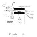
- FIG. 17 illustrates a method for producing graphene according to a second embodiment of the present invention.
- FIG. 1 schematically illustrates a process for producing graphene according to a first embodiment of the present invention.
- a solution 102 of a metal alkoxide is provided in a spray/aerosol zone 104 .
- Droplets of the solution 102 are introduced into a heating zone 106 as a fine spray, mist or aerosol 108 .
- the droplets 108 are carried into the heating zone 106 by means of a carrier gas 110 .
- the metal alkoxide thermally decomposes to form graphene 112 , 114 .
- the graphene may form as a powder 112 which may be collected in a cooler collection zone 116 .
- the graphene may also form as a thin film 114 on a substrate 118 placed in the heating zone 106 .
- FIG. 2 shows an apparatus suitable for producing graphene according to the method of the present invention.
- the apparatus includes a sprayer 10 , a quartz furnace tube 12 heated inside a furnace 14 , and a collection vessel 16 .
- the sprayer 10 contains a metal alkoxide solution 18 , preferably a solution of a metal alkoxide in an alcohol.
- the sprayer 10 is connected to a supply of gas 20 , preferably an inert gas such as argon, which is passed through the sprayer 10 and nozzle 22 to create a spray or a fine mist or aerosol 24 of the metal alkoxide solution.
- the flow of gas carries the droplets 24 of metal alkoxide solution through the heated quartz furnace tube 12 , such that the metal alkoxide thermally decomposes to form graphene.
- the graphene may form as a powder 30 , which deposits on the cooler parts of the furnace tube 12 .
- Graphene powder may also be collected in the collection vessel 16 , as shown in FIG. 2 .
- the graphene powder falls under its own weight to the bottom of the collection vessel 16 , whereas the gas is exhausted through the outlet 34 of the collection vessel.
- graphene films 36 may be produced, on the walls of the furnace tube 12 , and/or on a substrate 38 located in a hot region of the furnace.
- the process may continue for as long as the metal alkoxide solution is available. In this way, the process can be operated as a continuous, or quasi-continuous, process.
- Sodium ethoxide may be obtained, for example, by (a) the addition of sodium (Na) to ethanol (CH 3 CH 2 OH) or (b) the addition of sodium hydroxide (NaOH) to ethanol or (c) addition of sodium carbonate (Na 2 CO 3 ) to ethanol.
- sodium ethoxide may be used, as purchased.
- the sodium ethoxide (NaOCH 2 CH 3 ) may be left in solution in the ethanol.
- Typical concentrations used vary between about 0.5 M (0.57 g of Na in 50 ml of ethanol) and 1.7 M (1.95 g Na in 50 ml of ethanol).
- sodium carbonate Na 2 CO 3
- ethanol aqueous ethanol
- water can be removed by the addition of 3 A molecular sieves but it is not essential.
- 0.1 g of sodium ethoxide NaOCH 2 CH 3
- typical concentrations range from about 0.5 M to about 1.7 M.
- concentrations of sodium ethoxide (NaOCH 2 CH 3 ) given above are by way of example only, and can be higher or lower than the values described. However, the saturation concentration (therefore the maximum) of sodium ethoxide in ethanol is achieved at 21 weight % which is approximately 3 M.
- concentration of the sodium ethoxide solution used is varied according to the desired application. For example, when graphene films are to be produced, a relatively low concentration of sodium ethoxide is used (e.g. 0.5 M), whereas when graphene powder is to be produced, a relatively high concentration is used (e.g. 1.7 M).
- the sprayer 10 After the solution 18 is prepared, it is added to the sprayer 10 , which is then connected to the furnace tube 12 that sits inside the furnace 14 .
- the sprayer 10 has a volume of approximately 1 liter
- the furnace tube 12 is a quartz tube 12 having a length of 900 mm and a diameter of 28 mm.
- the furnace tube 12 may have any length and diameter, and may be made of any material, provided that it can withstand the temperature and alkaline/basic conditions of the process.
- An inert gas 20 is then flowed through the system (that is, through the sprayer 10 , furnace tube 12 , and collection vessel 16 ) at 70 ml/min.
- the inert gas may be argon, although any inert gas may be used.
- the furnace 14 is heated to 900 degrees Celsius at a rate of 20 degrees Celsius per minute and then held at this temperature for the duration of the process.
- the temperature of the furnace 14 only needs to be higher than the decomposition point of the metal alkoxide, which is 300 degrees Celsius in the case of sodium ethoxide (NaOCH 2 CH 3 ) and 350 degrees Celsius in the case of sodium methoxide (NaOCH 3 ).
- a higher temperature may be used.
- any higher temperature which practical for a tube furnace may be used, e.g. up to about 1800 degrees Celsius.
- a spray/fine mist/aerosol 24 of sodium ethoxide (NaOCH 2 CH 3 ) in ethanol is generated by increasing the flow rate of the inert gas 20 through the sprayer 10 to a flow rate of 170 ml/min.
- the flow rate may be adjusted to above or below this value stated. However, if the flow rate is too low no spray will be generated, and if it is too high the spray will pass rapidly through the furnace tube 12 with only minimal reaction. If the flow rate is too high, a jet of liquid may be produced, rather than a spray.
- the minimum flow rate required to produce a spray depends on the actual sprayer used, in particular the nozzle size of the sprayer.
- the mist/spray/aerosol 24 generated at the nozzle 22 of the sprayer 10 is carried through the furnace tube 12 , which is held at 900 degrees Celsius (see above).
- sodium ethoxide NaOCH 2 CH 3
- argon gas flow rate 170 ml/min, this would take approximately 20-30 mins.
- the sodium ethoxide solution 18 sprayed into the hot furnace tube 12 undergoes thermal decomposition to produce graphene powder 30 and graphene films 36 .
- the uniform hot zone of the furnace 14 extends approximately 10 cm either side of the centre. Outside this region there is likely to be a small temperature gradient.
- Graphene powder 30 deposits on the cooler parts of the quartz furnace tube 12 and can be collected in a vessel 16 connected to the opposite end of the furnace tube 12 from the sprayer unit 12 , as shown in FIG. 2 .
- the yield of carbon is approximately. 5-10%, based on mass of sodium ethoxide (NaOCH 2 CH 3 ). However, it is difficult to determine the yield accurately, as sometimes not all of the graphene is recovered as it can be stuck to the walls of the furnace tube 12 .
- graphene films 36 are produced on the walls of the furnace tube 12 .
- a graphene film 36 may be produced on a substrate 38 placed in the hot zone of the furnace tube 12 .
- Any substrate may be used, provided that it is capable of withstanding the temperature of the furnace.
- graphene films 36 have been grown on substrates 38 comprising silicon (Si) or silicon oxide (SiO 2 ) placed in the hot zone of the furnace tube 12 .
- the substrate may comprise a metal, in particular a non-catalytically active metal such as gold, silver, or steel, or may comprise a high-temperature plastic or glass.
- a graphene film 36 the same conditions as described above may be used, except that relatively low concentrations of sodium ethoxide are used (for example, 0.5 M solutions or lower), and/or the spraying time is reduced (for example, to a few minutes).
- the flow rate of the inert gas 20 can also be varied to control the amount of sodium ethoxide solution delivered to the hot zone of the furnace tube 12 .
- the thickness of the film 36 can be controlled by controlling the spraying time, with longer spraying times producing thicker films.
- a film thickness of 350 nm on a SiO 2 surface was obtained using a 1.7 M solution of sodium ethoxide in ethanol, sprayed into a furnace at 900 degrees Celsius for 20 mins, using an argon flow rate of 170 ml/min.
- Thinner films (ca. 20-30 nm) on Si were grown using 0.5 M solution sprayed into a furnace at 900 degrees Celsius for 6 mins, at an argon flow rate of 170 ml/min.
- furnace tube 12 After spraying is stopped the furnace tube 12 is cooled to room temperature in flowing argon (at a flow rate of 70 ml/min) before opening it up to the atmosphere.
- the products 30 , 36 are collected from the walls of the furnace tube 12 and from the collection vessel 16 , and then purified from the sodium carbonate (NaCO 3 ) and sodium hydroxide (NaOH) which are also formed in the reaction.
- This may be achieved by sonicating the black solid product in water (for example, using 10 mg of solid per 5 ml of water), followed by acidification of the resulting solution using hydrochloric acid (HCl at a concentration of M) until a pH of 1.0 is reached.
- the suspension is then centrifuged (at 11,000 rpm, 15557 g) for 20 minutes, the supernatant decanted and replaced with high purity water, and the suspension sonicated and centrifuged once again.
- the graphene solid was finally isolated by filtration over a nylon membrane having a 0.2 micron pore size).
- the graphene solid can be further annealed at high temperatures 400-3000 degrees Celsius for several hours to improve crystallinity.
- FIG. 3 shows the Raman spectrum of as-produced graphene.
- the as-produced material shows the characteristic G (graphitic carbon) band peak at ca. 1580 cm ⁇ 1 corresponding to values previously reported for graphene.
- the G′ band was observed at 2674 cm ⁇ 1 .
- the presence of a D band at ca. 1350 cm ⁇ 1 could suggest the presence of some defects, or simply the excitation of the numerous edges of the graphene particles likely to be present in the area of the material sampled.
- FIG. 4 shows the results of thermogravimetric analysis (TGA) in air of the as-produced graphene solid recovered from the furnace.
- TGA thermogravimetric analysis
- the degradation temperature of the material also increases from ca. 400 degrees Celsius for the as-produced graphene powder, to 620 degrees Celsius for the purified graphene, which is a degradation temperature expected for graphene, as can be seen in FIG. 5 .
- FIG. 6 shows the results of X-ray photoelectron spectroscopy (XPS) of the as-produced solid, confirming the by-products present in the as-produced material to be predominately sodium salts, having 15 at % sodium content (Na 1s peak at 1072 eV).
- XPS X-ray photoelectron spectroscopy
- FIG. 7 On close inspection of the carbon peak, shown in FIG. 7 , we observe the characteristic C 1s peak for graphitic carbon at 284.6 eV and a peak at 289.4 eV (characteristic of carbonate salts).
- XPS also showed the effectiveness of the purification step, showing a vastly reduced sodium content (0.97 at %) and the disappearance of the carbonate peak in the C 1s region.
- the data indicates the formation of graphene as opposed to graphene oxide or highly disordered graphene as there are no significant shoulders (characteristic of C—O or C ⁇ O groups) present on the graphitic carbon peak at 284.6 eV in FIG. 7 .
- FIG. 8 shows an SEM image of a particle from the as-produced graphene powder.
- Various particle sizes could be defined ranging from 1 to 100 microns.
- FIG. 9 By increasing the magnification of the particle shown in FIG. 8 , small bundled structures were observed on the surface and embedded in the particle, as can be seen in FIG. 9 . These bundles had an apparent sheet-like structure, suggesting that they were agglomerates of graphene possibly encased within large particles of the metal salts.
- Energy dispersive X-ray (EDX) spectroscopy showed these structures to be made up of mainly carbon with small amounts of sodium and oxygen present, as shown in FIG. 10 .
- FIG. 11 shows one sheet of graphene sitting on top of a second sheet. The sheets varied in dimensions but were typically a few microns in size.
- FIG. 12 shows a high resolution TEM image of a region that was densely packed with graphene, with the edges parallel to the electron beam. It shows areas where few-layer graphene is present and the separation between the layers of approximately 0.35 nm is clearly visible, providing good evidence for the production of well-ordered and crystalline graphene.
- Atomic force microscopy is a common technique used to characterise nanostructures. From the AFM image of the purified material shown in FIG. 13 a , we observe sheet like structures 2-3 microns in size. Sectional analysis of the graphene particle shown in FIGS. 13 b and c demonstrates that it is flat and, in this case, has a height between 0.8 and 1 nm, indicating that up to 3 layers could be present in this particular particle.
- the films produced by the process of the present invention have similar spectroscopic properties to the graphene powder.
- EDX spectroscopy shows that the graphene film is made up of predominately carbon.
- An EDX spectrum of a region of a graphene film obtained by the process of the present invention is shown in FIG. 15 .
- FIG. 16 shows an XPS spectrum for the graphene film, showing the characteristic C 1s peak for graphitic carbon at 284.6 eV.
- graphene oxide or highly disordered graphene is ruled out as there are no significant shoulders (characteristic of C—O or C ⁇ O groups) present on the graphitic C is peak at 284.6 eV.
- the sheet resistance of the graphene film was measured, using a 4-point probe in the van der Paaw geometry, to be on average 22.6 k ⁇ ⁇ 1 , which is in line with other reported values for graphene films.
- the ethanol in the above example acts mainly as a carrier for the sodium ethoxide.
- Metal alkoxides are solids having a low vapour pressure, so it is difficult to obtain sufficient metal alkoxide vapour to produce useful quantities of graphene by thermal decomposition of a pure metal alkoxide vapour.
- An advantage of the present invention is therefore that, by using a solution of a metal alkoxide, it is possible to introduce relatively large amounts of the alkoxide into the reaction zone, to obtain a relatively high yield and production rate of graphene.
- the yield of graphene is likely to depend on the presence of ethanol as well as sodium ethoxide (NaOCH 2 CH 3 ).
- the process described above is generally a chemical vapour deposition (CVD) process.
- the process according to the present invention has several advantages over the chemical vapour deposition (CVD) methods previously used to produce graphene, which involved using CVD to react methane and hydrogen on a transition metal catalyst.
- the present invention does not require any transition metal catalyst, thereby reducing the cost of production of graphene, and avoiding the difficulties of removing the catalyst from the product.
- the present invention provides a process by which graphene films can be grown directly onto any desired substrate, for example, a substrate such as silicon, silicon oxide, or silicon carbide, and thereby bypasses the step of transferring a film from a metal catalyst to the required substrate.
- the non-carbon byproducts are water-soluble, easy to remove and can be recycled to make more sodium ethoxide.
- the process can be carried out using any metal alkoxide (for example, MOR, where the metal M is one of sodium (Na), potassium (K), or lithium (Li), or M 2 (OR) 2 where the metal M is magnesium (Mg), and where R is any alkyl group such as methyl, ethyl, propyl, butyl or longer chains and variations thereof).
- MOR metal alkoxide
- R is any alkyl group such as methyl, ethyl, propyl, butyl or longer chains and variations thereof.
- any alcohol (R′—OH) may be used.
- the alkyl group (R) of the alkoxide and the alkyl group (R′) of the alcohol in which it is dissolved are the same, as in the example of sodium ethoxide/ethanol described above.
- the solvent is preferably an alcohol, other solvents may be used, in particular polar solvents, provided that the alkoxide does not react with the solvent.
- a metal alkoxide may be obtained by any of the following methods: addition of a metal to an alcohol, addition of a metal hydroxide to an alcohol, or addition of a metal carbonate to an alcohol.
- the metal alkoxide may be dissolved in alcohol to produce the solution.
- the metal alkoxide may be produced as a solution in the alcohol and need not be isolated.
- commercially available metal alkoxide or metal alkoxide solution may be used. The metal alkoxide does not need to be treated by any special process.
- the spraying of the metal alkoxide solution into the furnace tube can continue for as long as the metal alkoxide solution is available.
- the process according to the present invention can therefore be implemented as a continuous process, by providing a continuous supply of metal alkoxide solution to the sprayer.
- Graphene films may be produced on substrates in a batch process, or by moving substrates through the hot zone of the furnace in a conveyor-belt fashion, in order to deposit graphene films on large numbers of substrates in a substantially continuous manner.
- the rate of production of graphene may be controlled by controlling the concentration of the metal alkoxide solution and/or the flow rate of the gas. Higher concentrations of the metal alkoxide solution give a higher rate of production of graphene.
- the amount of material entering the hot zone can also be controlled by the rate of spraying which can be varied by controlling the flow rate of gas through the spray unit.
- the gas flow may be controlled by electronic mass flow controllers, but simple valves and bubble meters could also be used.
- the temperature of the furnace can also be varied to any temperature above the decomposition point of the metal alkoxide.
- an inert gas is continuously flowed through the furnace tube 12 during the formation of graphene
- a simple sprayer was used.
- various spraying devices could be used.
- various spraying devices may be used, including but not limited to liquid injection, syringe pump devices, atomizers, nebulizers and ultrasonic nebulizers.
- Droplets of various sizes may be produced.
- the solution could be sprayed directly into an evacuated hot zone, rather than using a carrier gas to transport the droplets through the hot zone.
- the rapidly-heated droplets may be vaporised prior to thermal decomposition, although thermal decomposition may occur directly from the liquid phase.
- the apparatus described above uses a furnace tube but any vessel or chamber that can be heated and where droplets of metal alkoxide in solution can be introduced could be used.
- the heated furnace tube, vessel or chamber can be any size.
- the collection vessel or chamber could involve a filter where the solid powder collects and the gas passes through.
- the heated furnace tube is shown as horizontal.
- a furnace tube could also be used vertically and metal alkoxide solutions added from the top as a flowing liquid or as droplets or a vapour.
- the graphene powder produced can simply be collected from the bottom, after settling into a collecting chamber of any dimensions, and the gas recycled.
- FIG. 17 illustrates a method for producing graphene according to a second embodiment of the present invention.
- This method is similar to the method of the first embodiment, in that a metal alkoxide is thermally decomposed to produce graphene in a hot region 200 of a decomposition apparatus 202 .
- the metal alkoxide is produced in situ, in the hot region 200 .
- a first reagent, in the form of sodium carbonate, is provided in a boat 204 in a hot region 200 of a furnace tube 206 .
- a second reagent 208 in the form of ethanol, is introduced into the hot region 200 by spraying. The ethanol reacts with the sodium carbonate to produce a metal alkoxide, in the form of sodium ethoxide, which thermally decomposes to produce graphene, in the form of graphene powder which collects in the boat 204 .
- the boat 204 is removed to collect the graphene, and another boat of the first reagent is introduced to the furnace tube 206 , so that the production of graphene may continue substantially continuously.
- the furnace tube 206 used in the second embodiment may be the same as that used in the first embodiment, and is described above.
- the heating rate is exactly as before apart from the final temperature is now 800 degrees Celsius in order to be below 851 degrees Celsius, the decomposition point of the sodium carbonate.
- the flow of ethanol and argon is also the same. Heating up to 800 degrees Celsius is carried out with an argon flow rate of 70 ml/min which is increased to 170 when the required temperature is reached, which sprays the ethanol into the furnace.
- the sodium carbonate (typically 1.5 g, but this varies according to the size of the boat 204 used) is placed in a boat 204 in the middle of the furnace 206 and the ethanol spray 208 which is vaporized at these temperatures simply passes over the top of the carbonate which produces the sodium ethoxide which immediately decomposes to graphene plus sodium carbonate and sodium hydroxide.
- the graphene powder collected may be purified as described in Step 4 of the first embodiment.
- the production of graphene continues for as long as the first and second reagents are available.
- the thermal decomposition of the metal alkoxide produces the carbonate and hydroxide of the metal as byproducts. These byproducts may in turn react with the first reagent to produce graphene.
- the first and second reagents may be continuously or intermittently replenished in order to operate the process substantially continuously. For example, in order to carry out the process on a commercial scale, a vertical tube furnace can be used, and the sodium carbonate simply dropped through it whilst spraying ethanol. The graphene would then just simply be collected at the bottom.
Applications Claiming Priority (3)
| Application Number | Priority Date | Filing Date | Title |
|---|---|---|---|
| GB0913011.3 | 2009-07-27 | ||
| GBGB0913011.3A GB0913011D0 (en) | 2009-07-27 | 2009-07-27 | Graphene |
| PCT/GB2010/051099 WO2011012874A1 (en) | 2009-07-27 | 2010-07-02 | Production of graphene from metal alkoxide |
Publications (2)
| Publication Number | Publication Date |
|---|---|
| US20120114551A1 US20120114551A1 (en) | 2012-05-10 |
| US9932227B2 true US9932227B2 (en) | 2018-04-03 |
Family
ID=41066864
Family Applications (1)
| Application Number | Title | Priority Date | Filing Date |
|---|---|---|---|
| US13/384,881 Active 2033-01-01 US9932227B2 (en) | 2009-07-27 | 2010-07-02 | Production of graphene from metal alkoxide |
Country Status (8)
| Country | Link |
|---|---|
| US (1) | US9932227B2 (ja) |
| EP (1) | EP2459484B1 (ja) |
| JP (2) | JP5767218B2 (ja) |
| KR (3) | KR101965882B1 (ja) |
| CN (1) | CN102498061A (ja) |
| ES (1) | ES2651675T3 (ja) |
| GB (1) | GB0913011D0 (ja) |
| WO (1) | WO2011012874A1 (ja) |
Families Citing this family (34)
| Publication number | Priority date | Publication date | Assignee | Title |
|---|---|---|---|---|
| WO2011017338A2 (en) * | 2009-08-03 | 2011-02-10 | University Of Idaho | Method for making graphene |
| US8796361B2 (en) | 2010-11-19 | 2014-08-05 | Ppg Industries Ohio, Inc. | Adhesive compositions containing graphenic carbon particles |
| US20140150970A1 (en) | 2010-11-19 | 2014-06-05 | Ppg Industries Ohio, Inc. | Structural adhesive compositions |
| US20110086756A1 (en) * | 2010-12-20 | 2011-04-14 | Gao hong-jun | Method for preparing silicon intercalated monolayer graphene |
| CA2857947C (en) * | 2011-03-15 | 2015-08-04 | Peerless Worldwide, Llc | Facile synthesis of graphene, graphene derivatives and abrasive nanoparticles and their various uses, including as tribologically-beneficial lubricant additives |
| KR101349912B1 (ko) | 2011-04-27 | 2014-01-13 | 한국지질자원연구원 | Pt/GR(Graphene) 나노복합체 및 그 제조방법 |
| WO2013006429A1 (en) * | 2011-06-30 | 2013-01-10 | Northwestern University | Crumpled particles, methods of synthesizing same and applications using same |
| US20130266501A1 (en) * | 2011-07-05 | 2013-10-10 | Rutgers, The State University Of New Jersey | Direct Production of Large and Highly Conductive Low-Oxygen Graphene Sheets and Monodispersed Low-Oxygen Graphene Nanosheets |
| US9938416B2 (en) | 2011-09-30 | 2018-04-10 | Ppg Industries Ohio, Inc. | Absorptive pigments comprising graphenic carbon particles |
| US10240052B2 (en) | 2011-09-30 | 2019-03-26 | Ppg Industries Ohio, Inc. | Supercapacitor electrodes including graphenic carbon particles |
| US10294375B2 (en) | 2011-09-30 | 2019-05-21 | Ppg Industries Ohio, Inc. | Electrically conductive coatings containing graphenic carbon particles |
| US9988551B2 (en) | 2011-09-30 | 2018-06-05 | Ppg Industries Ohio, Inc. | Black pigments comprising graphenic carbon particles |
| US9475946B2 (en) | 2011-09-30 | 2016-10-25 | Ppg Industries Ohio, Inc. | Graphenic carbon particle co-dispersions and methods of making same |
| US10763490B2 (en) | 2011-09-30 | 2020-09-01 | Ppg Industries Ohio, Inc. | Methods of coating an electrically conductive substrate and related electrodepositable compositions including graphenic carbon particles |
| US9832818B2 (en) | 2011-09-30 | 2017-11-28 | Ppg Industries Ohio, Inc. | Resistive heating coatings containing graphenic carbon particles |
| US9574094B2 (en) | 2013-12-09 | 2017-02-21 | Ppg Industries Ohio, Inc. | Graphenic carbon particle dispersions and methods of making same |
| US8486363B2 (en) | 2011-09-30 | 2013-07-16 | Ppg Industries Ohio, Inc. | Production of graphenic carbon particles utilizing hydrocarbon precursor materials |
| DE102011054103A1 (de) * | 2011-09-30 | 2013-04-04 | MAX-PLANCK-Gesellschaft zur Förderung der Wissenschaften e.V. | Verfahren zum Herstellen von Graphen-Nanobändern |
| US9761903B2 (en) | 2011-09-30 | 2017-09-12 | Ppg Industries Ohio, Inc. | Lithium ion battery electrodes including graphenic carbon particles |
| CN102515148B (zh) * | 2011-11-25 | 2013-12-25 | 东南大学 | 一种石墨烯铸体的铸造方法 |
| CN103159208A (zh) * | 2011-12-14 | 2013-06-19 | 海洋王照明科技股份有限公司 | 一种制备石墨烯的方法 |
| CN102627274B (zh) * | 2012-04-23 | 2013-11-06 | 中国科学院上海微系统与信息技术研究所 | 一种制备石墨烯的方法 |
| US11430979B2 (en) | 2013-03-15 | 2022-08-30 | Ppg Industries Ohio, Inc. | Lithium ion battery anodes including graphenic carbon particles |
| CN103332688B (zh) * | 2013-07-16 | 2015-08-19 | 中国科学院山西煤炭化学研究所 | 一种由有机酸金属盐合成石墨烯的方法 |
| CN103601177B (zh) * | 2013-11-19 | 2015-04-29 | 中国科学院山西煤炭化学研究所 | 一种碱金属盐催化固体有机酸制备石墨烯的方法 |
| KR101694751B1 (ko) * | 2014-08-21 | 2017-01-10 | (주)솔라세라믹 | 박막 형성을 위한 전구체 공급 장치 및 이를 포함하는 박막 형성 장치 |
| GB201416317D0 (en) * | 2014-09-16 | 2014-10-29 | Swan Thomas & Co Ltd | Two-dimensional materials |
| CN105036121A (zh) * | 2015-07-07 | 2015-11-11 | 哈尔滨工业大学 | 一种增强型石墨烯表面活性剂的制备方法 |
| KR101813584B1 (ko) | 2015-09-02 | 2017-12-29 | 한국과학기술연구원 | 탄소나노구조체 및 이의 제조 방법 |
| US10351661B2 (en) | 2015-12-10 | 2019-07-16 | Ppg Industries Ohio, Inc. | Method for producing an aminimide |
| US10377928B2 (en) | 2015-12-10 | 2019-08-13 | Ppg Industries Ohio, Inc. | Structural adhesive compositions |
| ITUB20161052A1 (it) * | 2016-02-25 | 2017-08-25 | Hygraner S R L | Metodo per la sintesi di grafene o di un suo derivato funzionalizzato, grafene o suo derivato funzionalizzato ottenuto da detto metodo e loro usi |
| WO2020236727A1 (en) | 2019-05-20 | 2020-11-26 | Nanograf Corporation | Anode active material including low-defect turbostratic carbon |
| CN110668432B (zh) * | 2019-09-27 | 2021-05-14 | 北京碳垣新材料科技有限公司 | 以金属粉末液相为基底生长石墨烯的装置 |
Citations (5)
| Publication number | Priority date | Publication date | Assignee | Title |
|---|---|---|---|---|
| US20060073275A1 (en) * | 2002-12-27 | 2006-04-06 | Shigeo Maruyama | Process and apparatus for producing single-walled carbon nanotube |
| US20070172409A1 (en) * | 2004-02-27 | 2007-07-26 | Takeshi Hikata | Catalyst structure and method of manufacturing carbon nanotube using the same |
| US20070298168A1 (en) * | 2006-06-09 | 2007-12-27 | Rensselaer Polytechnic Institute | Multifunctional carbon nanotube based brushes |
| US20080089828A1 (en) * | 2004-09-22 | 2008-04-17 | Showa Denko K.K. | Method for Producing Vapor Grown Carbon Nanotube |
| WO2009029984A1 (en) | 2007-09-03 | 2009-03-12 | Newsouth Innovations Pty Limited | Graphene |
Family Cites Families (2)
| Publication number | Priority date | Publication date | Assignee | Title |
|---|---|---|---|---|
| JPS60218344A (ja) * | 1984-04-14 | 1985-11-01 | Res Dev Corp Of Japan | アルミニウムアルコキシドの合成方法及びその装置 |
| US20090134369A1 (en) * | 2007-11-26 | 2009-05-28 | Applied Nanoworks, Inc. | Metal alkoxides, apparatus for manufacturing metal alkoxides, related methods and uses thereof |
-
2009
- 2009-07-27 GB GBGB0913011.3A patent/GB0913011D0/en not_active Ceased
-
2010
- 2010-07-02 JP JP2012522248A patent/JP5767218B2/ja not_active Expired - Fee Related
- 2010-07-02 CN CN2010800337284A patent/CN102498061A/zh active Pending
- 2010-07-02 EP EP10729930.7A patent/EP2459484B1/en active Active
- 2010-07-02 KR KR1020157017266A patent/KR101965882B1/ko active IP Right Grant
- 2010-07-02 KR KR1020177037556A patent/KR101987390B1/ko active IP Right Grant
- 2010-07-02 ES ES10729930.7T patent/ES2651675T3/es active Active
- 2010-07-02 KR KR1020127002126A patent/KR20120039665A/ko active Application Filing
- 2010-07-02 WO PCT/GB2010/051099 patent/WO2011012874A1/en active Application Filing
- 2010-07-02 US US13/384,881 patent/US9932227B2/en active Active
-
2015
- 2015-03-25 JP JP2015062526A patent/JP5932090B2/ja not_active Expired - Fee Related
Patent Citations (5)
| Publication number | Priority date | Publication date | Assignee | Title |
|---|---|---|---|---|
| US20060073275A1 (en) * | 2002-12-27 | 2006-04-06 | Shigeo Maruyama | Process and apparatus for producing single-walled carbon nanotube |
| US20070172409A1 (en) * | 2004-02-27 | 2007-07-26 | Takeshi Hikata | Catalyst structure and method of manufacturing carbon nanotube using the same |
| US20080089828A1 (en) * | 2004-09-22 | 2008-04-17 | Showa Denko K.K. | Method for Producing Vapor Grown Carbon Nanotube |
| US20070298168A1 (en) * | 2006-06-09 | 2007-12-27 | Rensselaer Polytechnic Institute | Multifunctional carbon nanotube based brushes |
| WO2009029984A1 (en) | 2007-09-03 | 2009-03-12 | Newsouth Innovations Pty Limited | Graphene |
Non-Patent Citations (26)
| Title |
|---|
| Avouris, P., Chen, Z.H. and Perebeinos, V., Nature Nanotech., 2007, 2, 605-615. |
| Bourlinos, A.B., Steriotis, T.A., Zboril, R., Georgakilas, V. and Stubos, A., J. Mater. Sci., 2009, 44, 1407-1411. |
| Bunch, J.S., van der Zande, A.M., Verbridge, S.S., Frank, I.W., Tanenbaum, D.M., Parpia, J.M., Craighead, H.G. and McEuen, P.L., Science, 2007, 315, 490-493. |
| Choucair M., et al.: Gram-scale Production of Graphene Based on Solvothermal Synthesis and Sonication; Natur Enanotechnology, vol. 4, Dec. 7, 2008; pp. 30-33; XP002610932. |
| CHOUCAIR M., THORDARSON P., STRIDE J.A.: "Gram-Scale Production of Graphene Based on Solvothermal Sysnthesis and Sonication", NATURE NANOTECHNOLOGY, NATURE PUBLISHING GROUP, LONDON, GB, vol. 4, 1 January 2009 (2009-01-01), GB, pages 30 - 33, XP002610932, ISSN: 1748-3387, DOI: 10.1038/NNANO.2008.365 |
| Dato, A, Radmilovic, V., Lee, Z.H., Phillips, J. and Frenklach, M., Nano Lett., 2008, 8, 2012-2016. |
| Eda, G., Fanchini, G. and Chhowalla, M., Nature Nanotech., 2008, 3, 270-274. |
| Emstev, K.V., Bostwick, A., Horn, K., Jobst, J., Kellogg, G.L., Ley, L., McChesney, J.L., Ohta, T., Reshanov, S.A., Rohrl, J., Rotenberg, E., Schmid, A.K., Waldmann, D., Weber, H.B. and Seyller, T., Nat. Mater., 2009, 8, 203-207. |
| Fowler, J.D., Allen, M.J., Tung, V.C., Yang, Y., Kaner, R.B. and Weiller, B.H., ACS Nano, 2009, 3, 301-306. |
| Geim, A.K. and MacDonald, A.H., Physics Today, 2007, 60, 35-41. |
| Goknur Cambaz, et al., Noncatalytic synthesis of carbon nanotubes, graphene and graphite on SiC, Carbon 2008; 46: 841-849. * |
| Huang, et al., Patterned Growth and Contact Transfer of Well-Aligned Carbon Nanotube Films, J. Phys. Chem. B 1999; 103: 4223-4227. * |
| Hummers, W.S. and Offeman, R.E., J. Am. Chem. Soc., 1958, 80, 1339-1339. |
| International Search Report dated Dec. 6, 2010 in connection with PCT/GB2010/051099. |
| Jiao, L., Zhang, L., Wang, X., Diankov, G. and Dai, H., Nature, 2009, 458, 877-880. |
| Kosynkin, D.V., Higginbotham, A.L., Sinitskii, A., Lomeda, J.R., Dimiev, A., Price, B.K. and Tour, J.M., Nature, 2009, 458, 872-876. |
| Lee, C., Wei, X.D., Kysar, J.W. and Hone, J., Science, 2008, 321, 385-388. |
| Li, J.L., Kudin, K.N., McAllister, M.J., Prud'homme, R.K., Aksay, I.A. and Car, R., Phys. Rev. Lett., 2006, 96, 176101. |
| McAllister, M.J., Li, J.L., Adamson, D.H., Schniepp, H.C., Abdala, A.A., Liu, J., Herrera-Alonso, M., Milius, D.L., Car, R., Prud'homme, R.K. and Aksay, I.A., Chem. Mater., 2007, 19, 4396-4404. |
| Park, S. and Ruoff, R.S., Nat Nano, 2009, 4, 217-224. |
| Peigney, eta l., A Study of the Formation of Single- and Double-Walled Carbon Nanotubes by a CVD Method, J. Phys. chem. B. 2001; 105: 9699-9710. * |
| Schniepp, H.C., Li, J.L., McAllister, M.J., Sai, H., Herrera-Alonso, M., Adamson, D.H., Prud'homme, R.K., Car, R., Saville, D.A. and Aksay, I.A., J. Phys. Chem. B, 2006, 110, 8535-8539. |
| Somani, P.R., Somani, S.P. and Umeno, M., Chem. Phys. Lett., 2006, 430, 56-59. |
| Stankovich, S., Dikin, D.A., Piner, R.D., Kohlhaas, K.A., Kleinhammes, A., Jia, Y., Wu, Y., Nguyen, S.T. and Ruoff, R. S., Carbon, 2007, 45, 1558-1565. |
| Subrahmanyam, K.S., Vivekchand, S.R.C., Govindaraj, A. and Rao, C.N.R., J. Mater. Chem., 2008, 18, 1517-1523. |
| Vivekchand, et al., Carbon nanotubes by nebulized spray pyrolysis, Chemical Physics Letters 2004; 386: 313-318 (2004). * |
Also Published As
| Publication number | Publication date |
|---|---|
| JP5767218B2 (ja) | 2015-08-19 |
| EP2459484A1 (en) | 2012-06-06 |
| JP2015143187A (ja) | 2015-08-06 |
| KR101987390B1 (ko) | 2019-06-10 |
| ES2651675T3 (es) | 2018-01-29 |
| KR20150082683A (ko) | 2015-07-15 |
| KR101965882B1 (ko) | 2019-04-04 |
| JP2013500233A (ja) | 2013-01-07 |
| EP2459484B1 (en) | 2017-09-13 |
| CN102498061A (zh) | 2012-06-13 |
| JP5932090B2 (ja) | 2016-06-08 |
| US20120114551A1 (en) | 2012-05-10 |
| KR20180001601A (ko) | 2018-01-04 |
| KR20120039665A (ko) | 2012-04-25 |
| GB0913011D0 (en) | 2009-09-02 |
| WO2011012874A1 (en) | 2011-02-03 |
Similar Documents
| Publication | Publication Date | Title |
|---|---|---|
| US9932227B2 (en) | Production of graphene from metal alkoxide | |
| Adetayo et al. | Synthesis and fabrication of graphene and graphene oxide: A review | |
| Kim et al. | Nanofabrication by thermal plasma jets: From nanoparticles to low-dimensional nanomaterials | |
| Awasthi et al. | Synthesis of carbon nanotubes | |
| Kim et al. | Scalable manufacturing of boron nitride nanotubes and their assemblies: a review | |
| KR102307337B1 (ko) | 보론 나이트라이드 나노튜브 및 이의 제조방법 | |
| Herron et al. | Simple and scalable route for the ‘bottom-up’synthesis of few-layer graphene platelets and thin films | |
| EP2720978B1 (en) | Process for producing graphene | |
| JP4920574B2 (ja) | 単層、多層、機能化及びドープ処理カーボンナノチューブ、並びにそれらの複合物 | |
| Maitra et al. | Strategies for the synthesis of graphene, graphene nanoribbons, nanoscrolls and related materials | |
| WO2008054349A2 (en) | Carbon nanotube structures formed on large free floating substrates | |
| Das et al. | Graphene synthesis | |
| KR20100090551A (ko) | 그라펜 중공 나노구 제조방법 | |
| Sajibul et al. | Synthesis of graphene | |
| Liu et al. | Facile synthesis of pure boron nanotubes and nanofibers | |
| Tiwari | Innovative Graphene Technologies: Developments & Characterisation, Volume 1 | |
| KR100781289B1 (ko) | 자기 정렬된 탄소나노물질의 대면적 합성법 | |
| Datoa | EARLY CAREER SCHOLARS IN MATERIALS SCIENCE 2019: INVITED FEATURE PAPER | |
| Rashidi et al. | Carbon allotropes: synthesis and characterization | |
| Xuebin | Synthesis, Properties and Applications of BCN Nanosheets | |
| Ndwandwe | Synthesis and characterization of carbon nanomaterials using BIS (acetylacetonato) oxovanadium (IV), Manganese (III) Acetylacetonate, Co-Zn and CoAI as catalyst precursors. |
Legal Events
| Date | Code | Title | Description |
|---|---|---|---|
| AS | Assignment |
Owner name: UNIVERSITY OF DURHAM, UNITED KINGDOM Free format text: ASSIGNMENT OF ASSIGNORS INTEREST;ASSIGNOR:COLEMAN, KARL STUART;REEL/FRAME:027561/0166 Effective date: 20120110 |
|
| AS | Assignment |
Owner name: DURHAM GRAPHENE SCIENCE LIMITED, UNITED KINGDOM Free format text: ASSIGNMENT OF ASSIGNORS INTEREST;ASSIGNOR:UNIVERSITY OF DURHAM;REEL/FRAME:030759/0675 Effective date: 20130228 |
|
| AS | Assignment |
Owner name: APPLIED GRAPHENE MATERIALS UK LIMITED, UNITED KING Free format text: CHANGE OF NAME;ASSIGNOR:DURHAM GRAPHENE SCIENCE LIMITED;REEL/FRAME:032058/0108 Effective date: 20131025 |
|
| STCF | Information on status: patent grant |
Free format text: PATENTED CASE |
|
| CC | Certificate of correction | ||
| FEPP | Fee payment procedure |
Free format text: ENTITY STATUS SET TO SMALL (ORIGINAL EVENT CODE: SMAL); ENTITY STATUS OF PATENT OWNER: SMALL ENTITY |
|
| MAFP | Maintenance fee payment |
Free format text: PAYMENT OF MAINTENANCE FEE, 4TH YR, SMALL ENTITY (ORIGINAL EVENT CODE: M2551); ENTITY STATUS OF PATENT OWNER: SMALL ENTITY Year of fee payment: 4 |