US9868374B2 - Modular monocoque backrest - Google Patents
Modular monocoque backrest Download PDFInfo
- Publication number
- US9868374B2 US9868374B2 US15/074,797 US201615074797A US9868374B2 US 9868374 B2 US9868374 B2 US 9868374B2 US 201615074797 A US201615074797 A US 201615074797A US 9868374 B2 US9868374 B2 US 9868374B2
- Authority
- US
- United States
- Prior art keywords
- shroud
- restraint
- coupled
- front shroud
- back shroud
- Prior art date
- Legal status (The legal status is an assumption and is not a legal conclusion. Google has not performed a legal analysis and makes no representation as to the accuracy of the status listed.)
- Active, expires
Links
- 229920000049 Carbon (fiber) Polymers 0.000 claims abstract description 26
- 239000004917 carbon fiber Substances 0.000 claims abstract description 26
- VNWKTOKETHGBQD-UHFFFAOYSA-N methane Chemical compound C VNWKTOKETHGBQD-UHFFFAOYSA-N 0.000 claims abstract description 26
- 239000002131 composite material Substances 0.000 claims abstract description 22
- 239000000463 material Substances 0.000 claims description 20
- 230000007246 mechanism Effects 0.000 claims description 20
- 229910052782 aluminium Inorganic materials 0.000 claims description 8
- XAGFODPZIPBFFR-UHFFFAOYSA-N aluminium Chemical compound [Al] XAGFODPZIPBFFR-UHFFFAOYSA-N 0.000 claims description 8
- 239000011800 void material Substances 0.000 claims description 8
- 238000000034 method Methods 0.000 description 19
- 238000010168 coupling process Methods 0.000 description 7
- 230000008901 benefit Effects 0.000 description 6
- 230000008878 coupling Effects 0.000 description 6
- 238000005859 coupling reaction Methods 0.000 description 6
- 239000007769 metal material Substances 0.000 description 3
- 230000008569 process Effects 0.000 description 3
- 239000000853 adhesive Substances 0.000 description 2
- 230000001070 adhesive effect Effects 0.000 description 2
- 239000006260 foam Substances 0.000 description 2
- 210000004705 lumbosacral region Anatomy 0.000 description 2
- 238000004519 manufacturing process Methods 0.000 description 2
- 230000002787 reinforcement Effects 0.000 description 2
- 239000004593 Epoxy Substances 0.000 description 1
- 230000001133 acceleration Effects 0.000 description 1
- 230000006978 adaptation Effects 0.000 description 1
- 239000007767 bonding agent Substances 0.000 description 1
- 230000008859 change Effects 0.000 description 1
- 239000011248 coating agent Substances 0.000 description 1
- 238000000576 coating method Methods 0.000 description 1
- 238000010276 construction Methods 0.000 description 1
- 238000001816 cooling Methods 0.000 description 1
- 229920006332 epoxy adhesive Polymers 0.000 description 1
- 239000011152 fibreglass Substances 0.000 description 1
- 238000010438 heat treatment Methods 0.000 description 1
- 239000010985 leather Substances 0.000 description 1
- 229910052751 metal Inorganic materials 0.000 description 1
- 239000002184 metal Substances 0.000 description 1
- ISWSIDIOOBJBQZ-UHFFFAOYSA-N phenol group Chemical group C1(=CC=CC=C1)O ISWSIDIOOBJBQZ-UHFFFAOYSA-N 0.000 description 1
- 238000007747 plating Methods 0.000 description 1
- 229920005989 resin Polymers 0.000 description 1
- 239000011347 resin Substances 0.000 description 1
- 229920001169 thermoplastic Polymers 0.000 description 1
- 229920001187 thermosetting polymer Polymers 0.000 description 1
- 239000004416 thermosoftening plastic Substances 0.000 description 1
Images


Classifications
-
- B—PERFORMING OPERATIONS; TRANSPORTING
- B60—VEHICLES IN GENERAL
- B60N—SEATS SPECIALLY ADAPTED FOR VEHICLES; VEHICLE PASSENGER ACCOMMODATION NOT OTHERWISE PROVIDED FOR
- B60N2/00—Seats specially adapted for vehicles; Arrangement or mounting of seats in vehicles
- B60N2/64—Back-rests or cushions
-
- B—PERFORMING OPERATIONS; TRANSPORTING
- B60—VEHICLES IN GENERAL
- B60N—SEATS SPECIALLY ADAPTED FOR VEHICLES; VEHICLE PASSENGER ACCOMMODATION NOT OTHERWISE PROVIDED FOR
- B60N2/00—Seats specially adapted for vehicles; Arrangement or mounting of seats in vehicles
- B60N2/68—Seat frames
- B60N2/686—Panel like structures
-
- A—HUMAN NECESSITIES
- A47—FURNITURE; DOMESTIC ARTICLES OR APPLIANCES; COFFEE MILLS; SPICE MILLS; SUCTION CLEANERS IN GENERAL
- A47C—CHAIRS; SOFAS; BEDS
- A47C5/00—Chairs of special materials
- A47C5/12—Chairs of special materials of plastics, with or without reinforcement
-
- B—PERFORMING OPERATIONS; TRANSPORTING
- B60—VEHICLES IN GENERAL
- B60N—SEATS SPECIALLY ADAPTED FOR VEHICLES; VEHICLE PASSENGER ACCOMMODATION NOT OTHERWISE PROVIDED FOR
- B60N2/00—Seats specially adapted for vehicles; Arrangement or mounting of seats in vehicles
- B60N2/02—Seats specially adapted for vehicles; Arrangement or mounting of seats in vehicles the seat or part thereof being movable, e.g. adjustable
- B60N2/22—Seats specially adapted for vehicles; Arrangement or mounting of seats in vehicles the seat or part thereof being movable, e.g. adjustable the back-rest being adjustable
-
- B—PERFORMING OPERATIONS; TRANSPORTING
- B60—VEHICLES IN GENERAL
- B60N—SEATS SPECIALLY ADAPTED FOR VEHICLES; VEHICLE PASSENGER ACCOMMODATION NOT OTHERWISE PROVIDED FOR
- B60N2/00—Seats specially adapted for vehicles; Arrangement or mounting of seats in vehicles
- B60N2/64—Back-rests or cushions
- B60N2/66—Lumbar supports
- B60N2/667—Lumbar supports having flexible support member bowed by applied forces
-
- B—PERFORMING OPERATIONS; TRANSPORTING
- B60—VEHICLES IN GENERAL
- B60N—SEATS SPECIALLY ADAPTED FOR VEHICLES; VEHICLE PASSENGER ACCOMMODATION NOT OTHERWISE PROVIDED FOR
- B60N2/00—Seats specially adapted for vehicles; Arrangement or mounting of seats in vehicles
- B60N2/68—Seat frames
- B60N2/682—Joining means
-
- B—PERFORMING OPERATIONS; TRANSPORTING
- B60—VEHICLES IN GENERAL
- B60N—SEATS SPECIALLY ADAPTED FOR VEHICLES; VEHICLE PASSENGER ACCOMMODATION NOT OTHERWISE PROVIDED FOR
- B60N2/00—Seats specially adapted for vehicles; Arrangement or mounting of seats in vehicles
- B60N2/68—Seat frames
- B60N2/688—Particular seat belt attachment and guiding
-
- B—PERFORMING OPERATIONS; TRANSPORTING
- B60—VEHICLES IN GENERAL
- B60R—VEHICLES, VEHICLE FITTINGS, OR VEHICLE PARTS, NOT OTHERWISE PROVIDED FOR
- B60R22/00—Safety belts or body harnesses in vehicles
- B60R22/34—Belt retractors, e.g. reels
- B60R22/36—Belt retractors, e.g. reels self-locking in an emergency
-
- B—PERFORMING OPERATIONS; TRANSPORTING
- B64—AIRCRAFT; AVIATION; COSMONAUTICS
- B64D—EQUIPMENT FOR FITTING IN OR TO AIRCRAFT; FLIGHT SUITS; PARACHUTES; ARRANGEMENT OR MOUNTING OF POWER PLANTS OR PROPULSION TRANSMISSIONS IN AIRCRAFT
- B64D11/00—Passenger or crew accommodation; Flight-deck installations not otherwise provided for
- B64D11/06—Arrangements of seats, or adaptations or details specially adapted for aircraft seats
- B64D11/062—Belts or other passenger restraint means for passenger seats
-
- B—PERFORMING OPERATIONS; TRANSPORTING
- B64—AIRCRAFT; AVIATION; COSMONAUTICS
- B64D—EQUIPMENT FOR FITTING IN OR TO AIRCRAFT; FLIGHT SUITS; PARACHUTES; ARRANGEMENT OR MOUNTING OF POWER PLANTS OR PROPULSION TRANSMISSIONS IN AIRCRAFT
- B64D11/00—Passenger or crew accommodation; Flight-deck installations not otherwise provided for
- B64D11/06—Arrangements of seats, or adaptations or details specially adapted for aircraft seats
- B64D11/0647—Seats characterised by special upholstery or cushioning features
-
- B—PERFORMING OPERATIONS; TRANSPORTING
- B64—AIRCRAFT; AVIATION; COSMONAUTICS
- B64D—EQUIPMENT FOR FITTING IN OR TO AIRCRAFT; FLIGHT SUITS; PARACHUTES; ARRANGEMENT OR MOUNTING OF POWER PLANTS OR PROPULSION TRANSMISSIONS IN AIRCRAFT
- B64D11/00—Passenger or crew accommodation; Flight-deck installations not otherwise provided for
- B64D11/06—Arrangements of seats, or adaptations or details specially adapted for aircraft seats
- B64D11/0649—Seats characterised by special features for reducing weight
-
- Y—GENERAL TAGGING OF NEW TECHNOLOGICAL DEVELOPMENTS; GENERAL TAGGING OF CROSS-SECTIONAL TECHNOLOGIES SPANNING OVER SEVERAL SECTIONS OF THE IPC; TECHNICAL SUBJECTS COVERED BY FORMER USPC CROSS-REFERENCE ART COLLECTIONS [XRACs] AND DIGESTS
- Y02—TECHNOLOGIES OR APPLICATIONS FOR MITIGATION OR ADAPTATION AGAINST CLIMATE CHANGE
- Y02T—CLIMATE CHANGE MITIGATION TECHNOLOGIES RELATED TO TRANSPORTATION
- Y02T50/00—Aeronautics or air transport
- Y02T50/40—Weight reduction
Definitions
- the present disclosure relates to seats, and more specifically, to a seat with a modular monocoque backrest.
- a typical backrest may comprise an aluminum or metallic frame with shear panels, side beams, and cross bars to take inflight stress loads and crash loads.
- a heavy torque tube may also be introduced in the lumbar area, to take torsional loads in the forward direction caused by an asymmetric shoulder belt. Due to the amount of heavy metallic materials used, typical backrest structures may be heavy and costly.
- a seat backrest may comprise a front shroud.
- the front shroud may be formed from a first molded carbon fiber composite.
- the seat backrest may also comprise a back shroud.
- the back shroud may be coupled to the front shroud, and may be formed from a second molded carbon fiber composite.
- the seat backrest may also comprise an at least one back spar.
- the at least one back spar may be coupled between the front shroud and the back shroud, and may extend in a direction away from the front shroud and the back shroud.
- the seat backrest may also further comprise the following.
- a headrest bracket may be coupled at a first end to the back shroud, and at a second end to the front shroud.
- a lumbar support mechanism may be coupled to the front shroud.
- a restraint exit may be coupled to the back shroud.
- the restraint exit may define a void on the back shroud, and the void may be configured to allow passage of a shoulder restraint belt.
- a restraint inertia reel may be coupled to the back shroud.
- the restraint inertia reel may be configured to deploy and retract the shoulder restraint belt through the restraint exit.
- the restraint exit may comprise a restraint support having a top surface opposite of a bottom surface.
- the bottom surface may be coupled to the back shroud.
- a restraint bezel may be coupled to the top surface.
- the restraint exit may comprise the second carbon fiber composite material.
- the restraint exit may be molded with the back shroud such that the back shroud and the restraint exit comprise a single continuous part.
- the at least one back spar may comprise an aluminum material.
- the at least one back spar may comprise a plurality of cross bracings.
- a modular monocoque backrest may comprise a front shroud.
- the front shroud may have a cushion support surface opposite of a first connecting surface.
- the front shroud may comprise a first carbon fiber composite material.
- the modular monocoque backrest may comprise a back shroud.
- the back shroud may have a second connecting surface opposite of a back surface.
- the back shroud may comprise a second carbon fiber composite material.
- the second connecting surface of the back shroud may be integrally couple to the first connecting surface of the front shroud, such that the front shroud and the back shroud form a single integrated object.
- the modular monocoque backrest may also comprise an at least one back spar.
- the at least one back spar may have a top end opposite of a bottom end.
- the top end may be configured to couple at a first edge to the first connecting surface of the front shroud and couple at a second edge to the second connecting surface of the back shroud.
- the bottom end may extend in a direction away from the front shroud and the back shroud.
- the modular monocoque backrest may also further comprise the following.
- a headrest bracket may be coupled at a first end to the second connecting surface of the back shroud and coupled at a second end to the first connecting surface of the front shroud.
- a lumbar support mechanism may be coupled to the cushion support surface of the front shroud.
- a restraint exit may be coupled to a top of the back shroud. The restraint exit may define a void on the top of the back shroud, configured to allow passage of a shoulder restraint belt.
- a restraint inertia reel may be coupled to the second connecting surface of the back shroud. The restraint inertia reel may be configured to deploy and retract the shoulder restraint belt through the restraint exit.
- the restraint exit may comprise a restraint support coupled to the top of the back shroud and a restraint bezel coupled to the top of the restraint support.
- the restraint exit may comprise the second carbon fiber composite material.
- the restraint exit may be molded with the back shroud such that the back shroud and the restraint exit comprise a single continuous part.
- the at least one back spar may comprise an aluminum material.
- the at least one back spar may comprise a plurality of cross bracings.
- a method of manufacturing a modular monocoque backrest may comprise forming a front shroud having a cushion support surface opposite of a first connecting surface.
- the front shroud may comprise a first carbon fiber composite material.
- the method may comprise forming a back shroud having a second connecting surface opposite of a back surface.
- the back shroud may comprise a second carbon fiber composite material.
- the method may comprise coupling the first connecting surface of the front shroud to the second connecting surface of the back shroud.
- the method may also comprise coupling an at least one back spar to the front shroud and the back shroud.
- the back shroud may comprise a top end opposite of a bottom end.
- the top end may be configured to couple at a first edge to the first connecting surface of the front shroud and couple at a second edge to the second connecting surface of the back shroud.
- the bottom end may extend in a direction away from the front shroud and the back shroud.
- the front shroud may be coupled to the back shroud via an epoxy adhesive.
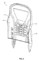
- FIG. 1A illustrates a front perspective view of a modular monocoque backrest, in accordance with various embodiments
- FIG. 1B illustrates a back perspective view of a modular monocoque backrest, in accordance with various embodiments
- FIG. 1C illustrates an exploded perspective view of a modular monocoque backrest, in accordance with various embodiments
- FIG. 2A illustrates a back perspective view of a modular monocoque backrest further comprising a restraint system, in accordance with various embodiments
- FIG. 2B illustrates a front perspective view of a back shroud of a modular monocoque backrest further comprising a restraint system, in accordance with various embodiments.
- FIG. 3 illustrates a front perspective view of a modular monocoque backrest further comprising a lumbar support mechanism, in accordance with various embodiments.
- any of the method or process descriptions may be executed in any order and are not necessarily limited to the order presented.
- any reference to singular includes plural embodiments, and any reference to more than one component or step may include a singular embodiment or step.
- any reference to attached, fixed, coupled, connected or the like may include permanent, removable, temporary, partial, full and/or any other possible attachment option.
- any reference to without contact (or similar phrases) may also include reduced contact or minimal contact. Surface shading lines may be used throughout the figures to denote different parts but not necessarily to denote the same or different materials.
- a modular monocoque backrest 100 is disclosed.
- Modular monocoque backrest 100 may be configured to provide a structure that is lighter in weight than conventional backrest structures, while also maintaining resistance to dynamic crash loads. Moreover, modular monocoque backrest 100 may also allow for exterior styling and decorative features without the need for additional exterior shrouding parts.
- modular monocoque backrest 100 may comprise any suitable lightweight and structurally durable material.
- modular monocoque backrest 100 may comprise a carbon fiber composite.
- Modular monocoque backrest 100 may also comprise a composite reinforcement material such as fiberglass and/or phenolic. Modular monocoque backrest 100 may be fabricated using any suitable carbon fiber manufacturing technique.
- modular monocoque backrest 100 may be fabricated using a carbon fiber layup method, and molded into any desired shape and/or size. Any suitable layup method may be used to fabricate modular monocoque backrest 100 .
- Modular monocoque backrest 100 may also comprise any suitable coating and/or cover.
- modular monocoque backrest 100 may be wrapped in leather, and/or any other suitable material, as desired.
- a carbon fiber composite molded design may enable modular monocoque backrest 100 to distribute and support stress loads through the external body of modular monocoque backrest 100 , without the need for additional metallic components for reinforcement.
- a carbon fiber composite molded design may also enable modular monocoque backrest 100 to modularly incorporate additional design features into the molded design, eliminating the need for additional external mounting brackets, hardware, and/or the like.
- modular monocoque backrest 100 may be molded to comprise a back literature pocket.
- Modular monocoque backrest 100 may also be molded to further comprise mounting brackets for a back literature pocket, and the back literature pocket may be fastened on.
- Modular monocoque backrest 100 may also be molded to comprise mounting provisions for speakers, lights, heating and/or cooling elements, arm rests, and/or any other suitable accessory.
- the use of a carbon fiber composite molded design may also enable modular monocoque backrest 100 to mold into any desired shape and/or size. Desired exterior styling and designs may therefore be incorporated without the need for extra exterior shrouding parts.
- modular monocoque backrest 100 may further distribute and support stress loads by incorporating support materials.
- support materials may be added to the interior of modular monocoque backrest 100 , in a position inward from the outer surfaces.
- modular monocoque backrest 100 may comprise a support material in the interior having a honeycomb structure.
- the honeycomb structure may comprise a carbon fiber material, and/or any other suitable material cable of providing further support to modular monocoque backrest 100 .
- the honeycomb structure may comprise a separate object from modular monocoque backrest 100 , or the honeycomb structure may also integrate with modular monocoque backrest 100 .
- a foam core may also be implemented in the interior of modular monocoque backrest 100 . The foam core may be configured to further distribute and support stress loads.
- modular monocoque backrest 100 may comprise a front shroud 110 , a back shroud 120 , and a back spar 130 .
- Front shroud 110 may be configured to provide structural support to modular monocoque backrest 100 .
- front shroud 110 may comprise a cushion support surface 112 and a connecting surface 114 .
- Cushion support surface 112 may comprise an outer surface of modular monocoque backrest 100 after front shroud 110 is coupled to back shroud 120 .
- Cushion support surface 112 may be configured to couple to a cushion, pad, and/or the like.
- Connecting surface 114 may comprise an inner surface of modular monocoque backrest 100 after front shroud 110 is coupled to back shroud 120 .
- connecting surface 114 may be configured as the surface of front shroud 110 that couples to back shroud 120 .
- back shroud 120 may be configured to provide further structural support to modular monocoque backrest 100 .
- Back shroud 120 may comprise a connecting surface 122 and a back surface 124 .
- Connecting surface 122 may comprise an inner surface of modular monocoque backrest 100 after front shroud 110 is coupled to back shroud 120 .
- connecting surface 122 may be configured as the surface of back shroud 120 that couples to front shroud 110 .
- Back surface 124 may comprise an outer surface of modular monocoque backrest 100 after front shroud 110 is coupled to back shroud 120 .
- front shroud 110 may be configured to couple to back shroud 120 .
- connecting surface 114 of front shroud 110 may be configured to couple to connecting surface 122 of back shroud 120 .
- Front shroud 110 may be coupled to back shroud 120 using any suitable technique.
- front shroud 110 may couple to back shroud 120 using an adhesive and/or bonding agent, such as an epoxy used for composite bonding, a resin, a thermoset, and/or a thermoplastic.
- Front shroud 110 may also couple to back shroud 120 using a mechanical fastener, such as a rivet, screw, and/or the like.
- Mechanical fasteners may be used at various intervals around the perimeter of modular monocoque backrest 100 to ensure a secure coupling between front shroud 110 and back shroud 120 .
- mechanical fasteners may be used at about every one inch, two inches, and/or any other suitable and/or desired interval.
- front shroud 110 may be coupled to back shroud 120 using a combination of coupling techniques, such as, for example, through the use of both an adhesive and a mechanical fastener.
- back spar 130 may provide a mounting point to mount modular monocoque backrest 100 to a surface, such as an aircraft floor, for example. Back spar 130 may also provide additional structural support for modular monocoque backrest 100 against torsional loads, inflight abuse loads, and/or crash loads. Back spar 130 may protrude downward from front shroud 110 and back shroud 120 .
- modular monocoque backrest 100 may comprise a plurality of back spars 130 .
- Back spar 130 may comprise any suitable material.
- back spar 130 may comprise a metal material, such as aluminum.
- back spar 130 may also comprise a carbon fiber material.
- Back spar 130 may be molded into front shroud 110 and/or back shroud 120 , such that back spar 130 and front shroud 110 and/or back shroud 120 may form a single continuous part.
- back spar 130 , front shroud 110 , and back shroud 120 may form an integral component in modular monocoque backrest 100 .
- back spar 130 may comprise a top end 132 opposite of a bottom end 134 .
- Top end 132 may comprise the end of back spar 130 proximate to modular monocoque backrest 100
- bottom end 134 may comprise the end of back spar 130 located furthest away from modular monocoque backrest 100 .
- Top end 132 may be configured to couple back spar 130 to modular monocoque backrest 100 .
- Top end 132 may be configured to couple to front shroud 110 and/or back shroud 120 .
- Top end 132 may be coupled to front shroud 110 and back shroud 120 using any suitable method, such as via a mechanical fastener.
- Top end 132 may be inserted between the coupling of front shroud 110 and back shroud 120 , and couple at a first edge to connecting surface 114 of front shroud 110 and at a second edge to connecting surface 122 of back shroud 120 .
- Bottom end 134 may comprise the mounting point for back spar 130 , and may be configured to mount to a surface, such as an aircraft floor for example.
- Back spar 130 may also comprise a plurality of cross bracings 137 , configured to provide additional structural support to modular monocoque backrest 100 .
- Cross bracings 137 may comprise a plurality of voids on the inner surface of back spar 130 , configured to increase the structural strength of back spar 130 . In this regard, the use of cross bracings 137 may also allow for a lighter weight back spar 130 .
- modular monocoque backrest 100 may also comprise a headrest bracket 140 .
- Headrest bracket 140 may be configured to receive a headrest (e.g., through headrest support holes 270 , as depicted in FIG. 2A ) and provide structural support for the headrest.
- headrest bracket 140 may comprise a plurality of voids 145 configured to receive and secure a headrest.
- Headrest bracket 140 may comprise any suitable material.
- headrest bracket 140 may comprise an aluminum material.
- Headrest bracket 140 may be coupled to connecting surface 114 of front shroud 110 and connecting surface 122 of back shroud 120 , such that headrest bracket 140 may fit between the coupling of front shroud 110 to back shroud 120 .
- headrest bracket 140 may also comprise a carbon fiber material. Headrest bracket may be molded directly with back shroud 120 , such that back shroud 120 and headrest bracket 140 may comprise a single continuous part. In this regard, headrest bracket 140 , front shroud 110 , and back shroud 120 may form an integral component in modular monocoque backrest 100 .
- a modular monocoque backrest 200 further comprising restraint devices is disclosed.
- modular monocoque backrest 200 may comprise a variety of restraint and safety devices and/or mechanisms.
- a restraint inertia reel 250 may be configured to deploy and retract a shoulder restraint belt 255 .
- Restraint inertia reel 250 may comprise a spring-loaded reel capable of deploying and retracting shoulder restraint belt 255 .
- Restraint inertia reel 250 may also comprise an inertial locking mechanism, or other such similar apparatus and/or mechanism, capable of preventing shoulder restraint belt 255 from deploying further during a sudden acceleration.
- Restraint inertia reel 250 may be coupled to connecting surface 122 of back shroud 120 . Restraint inertia reel 250 may be coupled to connecting surface 122 of back shroud 120 using a mounting bracket, bolt, and/or the like. In various embodiments, connecting surface 122 of back shroud 120 may be molded to comprise a mounting bracket for restraint inertia reel 250 . In that regard, restraint inertia reel 250 may bolt on to connecting surface 122 without the need for additional hardware and/or mounting brackets.
- shoulder restraint belt 255 may deploy from restraint inertia reel 250 through a restraint exit 260 . Shoulder restraint belt 255 may then be configured to connect to a female safety attachment member, such as restraint buckle and/or the like, located on a seat.
- Restraint exit 260 may comprise any suitable material, such as aluminum.
- restraint exit 260 may also comprise a carbon fiber material.
- restraint exit 260 may be molded directly into back shroud 120 , such that back shroud 120 and restraint exit 260 comprise a single continuous part. Restraint exit 260 may comprise a restraint support 268 and a restraint bezel 264 .
- Restraint support 268 may be configured to structurally guide and support shoulder restraint belt 255 while deployed. Restraint support 268 may be coupled to the top of back shroud 120 .
- back shroud 120 may be molded to comprise a void and restraint support 268 may substantially align with the void to allow shoulder restraint belt 255 to pass through the top of back shroud 120 .
- Restraint bezel 264 may be configured to protect restraint support 268 and to provide structural support for shoulder restraint belt 255 after shoulder restraint belt 255 is deployed. Restraint bezel 264 may also be decorative in nature, comprising a metal plating and/or the like.
- a modular monocoque backrest 300 further comprising a lumbar support mechanism 380 is depicted.
- Lumbar support mechanism 380 may be coupled to cushion support surface 112 of front shroud 110 .
- Lumbar support mechanism 380 may be located in any suitable location on cushion support surface 112 , such as, for example, in the general lumbar region of cushion support surface 112 .
- Lumbar support mechanism 380 may couple to cushion support surface 112 using any suitable technique, such as via a mounting bracket, fastener, bolt, and/or the like.
- cushion support surface 112 may also be molded to comprise mounting brackets, and/or the like, enabling lumbar support mechanism 380 to couple to cushion support surface 112 without the need of additional hardware and/or mounting brackets.
- lumbar support mechanism 380 may be configured to adjustably vary the amount of lumbar support in modular monocoque backrest 300 .
- lumbar support mechanism 380 may adjust to protrude outward from front shroud 110 .
- the outward protrusion may provide a passenger with greater support and comfort in the lumbar region.
- the adjusted lumbar support mechanism 380 may protrude outward causing a curvature of the cushion in the lumbar area.
- Lumbar support mechanism 380 may also comprise a mechanical and/or electrical device allowing for adjustment to the level of outward protrusion.
- lumbar support mechanism 380 may allow for a change in the protrusion amount to vary the distance lumbar support mechanism 380 is protruding away from front shroud 110 .
- Lumbar support mechanism 380 may be adjusted using any suitable device, such as, for example, through electronic controls, mechanical controls, and/or the like.
- references to “various embodiments”, “one embodiment”, “an embodiment”, “an example embodiment”, etc. indicate that the embodiment described may include a particular feature, structure, or characteristic, but every embodiment may not necessarily include the particular feature, structure, or characteristic. Moreover, such phrases are not necessarily referring to the same embodiment. Further, when a particular feature, structure, or characteristic is described in connection with an embodiment, it is submitted that it is within the knowledge of one skilled in the art to affect such feature, structure, or characteristic in connection with other embodiments whether or not explicitly described. After reading the description, it will be apparent to one skilled in the relevant art(s) how to implement the disclosure in alternative embodiments.
Landscapes
- Engineering & Computer Science (AREA)
- Aviation & Aerospace Engineering (AREA)
- Mechanical Engineering (AREA)
- Transportation (AREA)
- Seats For Vehicles (AREA)
- Chair Legs, Seat Parts, And Backrests (AREA)
Priority Applications (6)
| Application Number | Priority Date | Filing Date | Title |
|---|---|---|---|
| US15/074,797 US9868374B2 (en) | 2016-03-18 | 2016-03-18 | Modular monocoque backrest |
| CA2956758A CA2956758A1 (fr) | 2016-03-18 | 2017-01-30 | Dossier monocoque modulaire |
| EP17159520.0A EP3219616B1 (fr) | 2016-03-18 | 2017-03-07 | Dossier monocoque modulaire |
| BR102017004946-9A BR102017004946B1 (pt) | 2016-03-18 | 2017-03-13 | Encostos de assento e monobloco modular |
| CN201710160771.0A CN107200134B (zh) | 2016-03-18 | 2017-03-17 | 模块化单壳式靠背 |
| US15/836,412 US10071661B2 (en) | 2016-03-18 | 2017-12-08 | Modular monocoque backrest |
Applications Claiming Priority (1)
| Application Number | Priority Date | Filing Date | Title |
|---|---|---|---|
| US15/074,797 US9868374B2 (en) | 2016-03-18 | 2016-03-18 | Modular monocoque backrest |
Related Child Applications (1)
| Application Number | Title | Priority Date | Filing Date |
|---|---|---|---|
| US15/836,412 Division US10071661B2 (en) | 2016-03-18 | 2017-12-08 | Modular monocoque backrest |
Publications (2)
| Publication Number | Publication Date |
|---|---|
| US20170267146A1 US20170267146A1 (en) | 2017-09-21 |
| US9868374B2 true US9868374B2 (en) | 2018-01-16 |
Family
ID=58261567
Family Applications (2)
| Application Number | Title | Priority Date | Filing Date |
|---|---|---|---|
| US15/074,797 Active 2036-09-03 US9868374B2 (en) | 2016-03-18 | 2016-03-18 | Modular monocoque backrest |
| US15/836,412 Active US10071661B2 (en) | 2016-03-18 | 2017-12-08 | Modular monocoque backrest |
Family Applications After (1)
| Application Number | Title | Priority Date | Filing Date |
|---|---|---|---|
| US15/836,412 Active US10071661B2 (en) | 2016-03-18 | 2017-12-08 | Modular monocoque backrest |
Country Status (5)
| Country | Link |
|---|---|
| US (2) | US9868374B2 (fr) |
| EP (1) | EP3219616B1 (fr) |
| CN (1) | CN107200134B (fr) |
| BR (1) | BR102017004946B1 (fr) |
| CA (1) | CA2956758A1 (fr) |
Cited By (1)
| Publication number | Priority date | Publication date | Assignee | Title |
|---|---|---|---|---|
| USD825072S1 (en) * | 2016-12-06 | 2018-08-07 | The Raymond Corporation | Adjustable back pad |
Families Citing this family (9)
| Publication number | Priority date | Publication date | Assignee | Title |
|---|---|---|---|---|
| WO2015191709A2 (fr) | 2014-06-10 | 2015-12-17 | Zodiac Seats Us Llc | Sièges passagers de conception ergonomique monocoques et semi-monocoques |
| US10194750B2 (en) * | 2015-04-13 | 2019-02-05 | Steelcase Inc. | Seating arrangement |
| JP6245300B2 (ja) * | 2016-04-28 | 2017-12-13 | マツダ株式会社 | シートバック構造 |
| US10569680B2 (en) * | 2018-04-24 | 2020-02-25 | Lear Corporation | Seat assembly with adhered brackets |
| US10967772B2 (en) * | 2019-01-23 | 2021-04-06 | Volvo Car Corporation | Vehicle seat cushion carrier assembly for modular vehicle seat or the like |
| GB2582768B (en) * | 2019-04-01 | 2021-08-11 | Acro Aircraft Seating Ltd | Seat back |
| CN112406652B (zh) * | 2019-08-20 | 2023-09-29 | 安道拓工程技术知识产权有限公司 | 座椅靠背的靠背板安装结构及交通工具用座椅 |
| CN112369854A (zh) * | 2020-11-30 | 2021-02-19 | 上海晋飞碳纤科技股份有限公司 | 一种复合材料椅背的连接结构及制作方法 |
| US12075922B2 (en) * | 2022-09-08 | 2024-09-03 | Anthro Form, Llc | Chair having interchangeable decorative feature |
Citations (28)
| Publication number | Priority date | Publication date | Assignee | Title |
|---|---|---|---|---|
| US4108492A (en) * | 1974-10-18 | 1978-08-22 | Kirby Billy E | Back support |
| US4123105A (en) * | 1975-10-29 | 1978-10-31 | Interroyal Corporation | Chair construction |
| US4133579A (en) * | 1977-08-29 | 1979-01-09 | American Desk Manufacturing Co. | Stadium, gymnasium or like chair |
| US4555137A (en) * | 1982-06-18 | 1985-11-26 | Keiper Recaro Gmbh & Co. | Back rest for a vehicle seat, particularly a motor vehicle seat |
| US5048894A (en) * | 1988-11-09 | 1991-09-17 | Tokyo Seat Corp., Ltd. | Seat for special vehicle |
| US5662381A (en) * | 1991-05-30 | 1997-09-02 | Steelcase Inc. | Chair construction and method of assembly |
| US5879055A (en) * | 1996-09-24 | 1999-03-09 | Lear Corporation | Automative seat back panel |
| US5895096A (en) * | 1997-04-10 | 1999-04-20 | Lear Corporation | Vehicle seat back assembly and method of making a vehicle seat back assembly |
| DE19757060A1 (de) | 1997-12-20 | 1999-06-24 | Bayerische Motoren Werke Ag | Rückenlehne für ein Kraftfahrzeug |
| US5988757A (en) | 1996-08-29 | 1999-11-23 | Lear Corporation | Vehicle seat assembly |
| EP0972673A2 (fr) | 1998-06-20 | 2000-01-19 | Bayerische Motoren Werke Aktiengesellschaft, Patentabteilung AJ-3 | Siège pour véhicule automobile |
| US6189972B1 (en) * | 1998-06-05 | 2001-02-20 | Teknion Furniture Systems Inc. | Lumbar support adjustment mechanism |
| US20060061202A1 (en) | 2004-09-17 | 2006-03-23 | B/E Aerospace, Inc. | Adjustable seat belt guide assembly |
| US20060152062A1 (en) | 2004-12-20 | 2006-07-13 | Baultar I.D. Inc. | Adjustable ergonomic back for a seat |
| US20070138855A1 (en) | 2005-12-15 | 2007-06-21 | Recaro Gmbh & Co. Kg | Vehicle seat, in particular a sports seat |
| US20090045658A1 (en) | 2004-09-27 | 2009-02-19 | Mladen Humer | Vehicle seat having active head restraint system |
| US20100066145A1 (en) * | 2006-04-27 | 2010-03-18 | Takashi Akutsu | Vehicle seat |
| US7954762B2 (en) | 2006-05-17 | 2011-06-07 | The Boeing Company | Lightweight aircraft passenger seat with composite construction |
| US7967380B2 (en) * | 2004-10-28 | 2011-06-28 | Ts Tech Co., Ltd. | Vehicle seat with cushion plate and pressure adjusting mechanism |
| US8052213B2 (en) * | 2006-07-03 | 2011-11-08 | Milsco Manufacturing Company, A Unit Of Jason Incorporated | Seat with adjustable seat occupant support assembly and integrally formed seat shell therefor |
| US20130328371A1 (en) * | 2009-10-09 | 2013-12-12 | PAC Seating Systems, Inc. | Removable back shell for an aircraft seat |
| US20150008716A1 (en) * | 2013-07-02 | 2015-01-08 | Ford Global Technologies, Llc | Trim attachment apparatus for vehicle seating assembly |
| DE102013225477A1 (de) | 2013-08-30 | 2015-03-05 | Johnson Controls Gmbh | Sitzlehne für einen fahrzeugsitz und fahrzeugsitz |
| US20150145303A1 (en) * | 2013-01-24 | 2015-05-28 | Ford Global Technologies, Llc | Flexible seatback system |
| DE102013225963A1 (de) | 2013-12-13 | 2015-06-18 | Johnson Controls Gmbh | Sitzteil und Fahrzeugsitz |
| WO2015191709A2 (fr) | 2014-06-10 | 2015-12-17 | Zodiac Seats Us Llc | Sièges passagers de conception ergonomique monocoques et semi-monocoques |
| US20160009209A1 (en) | 2013-02-18 | 2016-01-14 | Faurecia Automotive Seating, Llc | Seat back for vehicle seat |
| US20160353891A1 (en) * | 2012-09-20 | 2016-12-08 | Steelcase Inc. | Chair Assembly |
Family Cites Families (16)
| Publication number | Priority date | Publication date | Assignee | Title |
|---|---|---|---|---|
| US3695696A (en) * | 1970-01-19 | 1972-10-03 | Allied Chem | Vehicle seat with integral seat and back portions |
| US3873155A (en) * | 1972-03-07 | 1975-03-25 | American Seating Co | Transit seat with contoured plastic shell |
| US3861747A (en) * | 1972-12-11 | 1975-01-21 | Norman Diamond | Modular seat for public use |
| FR2274553A1 (fr) * | 1974-06-14 | 1976-01-09 | Faure Bertrand | Coussin constitue d'une matelassure en au moins deux parties reunies dos a dos |
| US4722569A (en) * | 1985-09-13 | 1988-02-02 | Robin L. Morgenstern | Power and manually actuated lumbosacral backrest |
| US5451071A (en) * | 1993-09-16 | 1995-09-19 | Cannondale Corporation | Bicycle frame |
| US5582459A (en) * | 1993-09-30 | 1996-12-10 | Itoki Crebio Corporation | Chair having tiltable seat back |
| US5711575A (en) * | 1995-06-09 | 1998-01-27 | Herman Miller, Inc. | Office chair and adjustable lumbar support therefor |
| US5988748A (en) * | 1995-11-27 | 1999-11-23 | Lear Corporation | Automotive seat bottom assembly |
| US6378942B1 (en) * | 2000-06-20 | 2002-04-30 | Global Total Office | Backrest with adjustable lumbar support |
| US6557307B2 (en) * | 2001-06-11 | 2003-05-06 | Haworth, Inc. | Upright panel with height adjustable back cushion |
| ES1049384Y (es) * | 2001-06-12 | 2002-09-01 | Figueras Int Seating Sa | Respaldo para butacas perfeccionado. |
| JP5511310B2 (ja) * | 2009-10-27 | 2014-06-04 | 日本発條株式会社 | 車両用シート |
| EP2718180B1 (fr) * | 2011-06-07 | 2018-02-28 | Composite Helicopters International Holdings Limited | Hélicoptère |
| US9649963B2 (en) * | 2014-03-04 | 2017-05-16 | Ford Global Technologies, Pllc | Trim and foam assembly for a vehicle seat |
| US20170210263A1 (en) * | 2016-01-25 | 2017-07-27 | Ford Global Technologies, Llc | Integrated independent thigh supports |
-
2016
- 2016-03-18 US US15/074,797 patent/US9868374B2/en active Active
-
2017
- 2017-01-30 CA CA2956758A patent/CA2956758A1/fr active Pending
- 2017-03-07 EP EP17159520.0A patent/EP3219616B1/fr active Active
- 2017-03-13 BR BR102017004946-9A patent/BR102017004946B1/pt active IP Right Grant
- 2017-03-17 CN CN201710160771.0A patent/CN107200134B/zh active Active
- 2017-12-08 US US15/836,412 patent/US10071661B2/en active Active
Patent Citations (32)
| Publication number | Priority date | Publication date | Assignee | Title |
|---|---|---|---|---|
| US4108492A (en) * | 1974-10-18 | 1978-08-22 | Kirby Billy E | Back support |
| US4123105A (en) * | 1975-10-29 | 1978-10-31 | Interroyal Corporation | Chair construction |
| US4133579A (en) * | 1977-08-29 | 1979-01-09 | American Desk Manufacturing Co. | Stadium, gymnasium or like chair |
| US4555137A (en) * | 1982-06-18 | 1985-11-26 | Keiper Recaro Gmbh & Co. | Back rest for a vehicle seat, particularly a motor vehicle seat |
| US5048894A (en) * | 1988-11-09 | 1991-09-17 | Tokyo Seat Corp., Ltd. | Seat for special vehicle |
| US5662381A (en) * | 1991-05-30 | 1997-09-02 | Steelcase Inc. | Chair construction and method of assembly |
| US5988757A (en) | 1996-08-29 | 1999-11-23 | Lear Corporation | Vehicle seat assembly |
| US5879055A (en) * | 1996-09-24 | 1999-03-09 | Lear Corporation | Automative seat back panel |
| US5895096A (en) * | 1997-04-10 | 1999-04-20 | Lear Corporation | Vehicle seat back assembly and method of making a vehicle seat back assembly |
| DE19757060A1 (de) | 1997-12-20 | 1999-06-24 | Bayerische Motoren Werke Ag | Rückenlehne für ein Kraftfahrzeug |
| US6189972B1 (en) * | 1998-06-05 | 2001-02-20 | Teknion Furniture Systems Inc. | Lumbar support adjustment mechanism |
| US6260921B1 (en) * | 1998-06-05 | 2001-07-17 | Teknion Furniture Systems, Inc. | Lumbar support adjustment mechanism |
| EP0972673A2 (fr) | 1998-06-20 | 2000-01-19 | Bayerische Motoren Werke Aktiengesellschaft, Patentabteilung AJ-3 | Siège pour véhicule automobile |
| US20060061202A1 (en) | 2004-09-17 | 2006-03-23 | B/E Aerospace, Inc. | Adjustable seat belt guide assembly |
| US20090045658A1 (en) | 2004-09-27 | 2009-02-19 | Mladen Humer | Vehicle seat having active head restraint system |
| US7967380B2 (en) * | 2004-10-28 | 2011-06-28 | Ts Tech Co., Ltd. | Vehicle seat with cushion plate and pressure adjusting mechanism |
| US20110210588A1 (en) * | 2004-10-28 | 2011-09-01 | Ts Tech Co., Ltd. | Vehicle seat with cushion plate |
| US8132857B2 (en) * | 2004-10-28 | 2012-03-13 | Ts Tech Co., Ltd. | Vehicle seat with cushion plate |
| US20060152062A1 (en) | 2004-12-20 | 2006-07-13 | Baultar I.D. Inc. | Adjustable ergonomic back for a seat |
| US20070138855A1 (en) | 2005-12-15 | 2007-06-21 | Recaro Gmbh & Co. Kg | Vehicle seat, in particular a sports seat |
| US20100066145A1 (en) * | 2006-04-27 | 2010-03-18 | Takashi Akutsu | Vehicle seat |
| US7954762B2 (en) | 2006-05-17 | 2011-06-07 | The Boeing Company | Lightweight aircraft passenger seat with composite construction |
| US8052213B2 (en) * | 2006-07-03 | 2011-11-08 | Milsco Manufacturing Company, A Unit Of Jason Incorporated | Seat with adjustable seat occupant support assembly and integrally formed seat shell therefor |
| US20130328371A1 (en) * | 2009-10-09 | 2013-12-12 | PAC Seating Systems, Inc. | Removable back shell for an aircraft seat |
| US20150158591A1 (en) * | 2009-10-09 | 2015-06-11 | PAC Seating Systems, Inc. | Removable back shell for an aircraft seat |
| US20160353891A1 (en) * | 2012-09-20 | 2016-12-08 | Steelcase Inc. | Chair Assembly |
| US20150145303A1 (en) * | 2013-01-24 | 2015-05-28 | Ford Global Technologies, Llc | Flexible seatback system |
| US20160009209A1 (en) | 2013-02-18 | 2016-01-14 | Faurecia Automotive Seating, Llc | Seat back for vehicle seat |
| US20150008716A1 (en) * | 2013-07-02 | 2015-01-08 | Ford Global Technologies, Llc | Trim attachment apparatus for vehicle seating assembly |
| DE102013225477A1 (de) | 2013-08-30 | 2015-03-05 | Johnson Controls Gmbh | Sitzlehne für einen fahrzeugsitz und fahrzeugsitz |
| DE102013225963A1 (de) | 2013-12-13 | 2015-06-18 | Johnson Controls Gmbh | Sitzteil und Fahrzeugsitz |
| WO2015191709A2 (fr) | 2014-06-10 | 2015-12-17 | Zodiac Seats Us Llc | Sièges passagers de conception ergonomique monocoques et semi-monocoques |
Non-Patent Citations (1)
| Title |
|---|
| EP Search Report dated Jul. 27, 2017 in EP Application No. 17159520.0. |
Cited By (1)
| Publication number | Priority date | Publication date | Assignee | Title |
|---|---|---|---|---|
| USD825072S1 (en) * | 2016-12-06 | 2018-08-07 | The Raymond Corporation | Adjustable back pad |
Also Published As
| Publication number | Publication date |
|---|---|
| CA2956758A1 (fr) | 2017-09-18 |
| US20180099597A1 (en) | 2018-04-12 |
| CN107200134B (zh) | 2021-07-13 |
| BR102017004946A2 (pt) | 2017-09-26 |
| CN107200134A (zh) | 2017-09-26 |
| EP3219616B1 (fr) | 2020-05-13 |
| US10071661B2 (en) | 2018-09-11 |
| BR102017004946B1 (pt) | 2022-04-26 |
| EP3219616A1 (fr) | 2017-09-20 |
| US20170267146A1 (en) | 2017-09-21 |
Similar Documents
| Publication | Publication Date | Title |
|---|---|---|
| US10071661B2 (en) | Modular monocoque backrest | |
| CN102481978A (zh) | 飞机座椅和相关组件中的改进 | |
| US4498649A (en) | Aircraft seating | |
| EP3426556B1 (fr) | Dossier de siège d'aéronef avec bride périmétrique non tubulaire | |
| EP1714569A1 (fr) | Casque pour cycliste | |
| US20070138855A1 (en) | Vehicle seat, in particular a sports seat | |
| US10543923B2 (en) | Seat backrest | |
| EP3446978B1 (fr) | Siège escamotable profilé | |
| US20230322138A1 (en) | Structural assembly for passenger seat and associated methods | |
| US9499082B2 (en) | Motor vehicle | |
| KR101771011B1 (ko) | 하이브리드 타입의 차량용 리어 시트백 프레임 | |
| JP2019064416A (ja) | 車両用シート | |
| US10899457B2 (en) | Composite seat assemblies including high performance fibers | |
| JP5867300B2 (ja) | 車両用シートのシートバックフレームの締結構造 | |
| JP5771020B2 (ja) | 車両用シートバックフレーム構造 | |
| CN112407292A (zh) | 一种航空座椅与救生伞集成结构 | |
| JP6700887B2 (ja) | 乗物用シート | |
| CN109774561B (zh) | 一种用于汽车座椅的塑料靠背骨架 | |
| EP3107422B1 (fr) | Siège pour véhicules et son procédé de fabrication | |
| KR20230152534A (ko) | 벨트 어셈블리 및 차량용 장치 | |
| ITAN20140014U1 (it) | Sedile per veicoli |
Legal Events
| Date | Code | Title | Description |
|---|---|---|---|
| AS | Assignment |
Owner name: AMI INDUSTRIES, INC., COLORADO Free format text: ASSIGNMENT OF ASSIGNORS INTEREST;ASSIGNORS:FERGUSON, KEITH M.;HOOVER, DOUGLAS E.;REEL/FRAME:038036/0413 Effective date: 20160318 |
|
| STCF | Information on status: patent grant |
Free format text: PATENTED CASE |
|
| MAFP | Maintenance fee payment |
Free format text: PAYMENT OF MAINTENANCE FEE, 4TH YEAR, LARGE ENTITY (ORIGINAL EVENT CODE: M1551); ENTITY STATUS OF PATENT OWNER: LARGE ENTITY Year of fee payment: 4 |